Article

An Adaptive Centralized Protection and Relay Coordination Algorithm for Microgrid

by
Regin Bose Kannaian
1,
Belwin Brearley Joseph
2,* and
Raja Prabu Ramachandran
3
1
Computer Science Engineering Faculty, Chennai Institute of Technology, Chennai 600048, India
2
Electrical and Electronics Engineering Faculty, School of Electrical and Communication Sciences, B.S Abdur Rahman Crescent Institute of Science and Technology, Chennai 600048, India
3
Electrical and Electronics Engineering Faculty, Gandhi Institute of Technology and Management, Visakhapatnam 530045, India
*
Author to whom correspondence should be addressed.
Energies 2023, 16(12), 4820; https://doi.org/10.3390/en16124820
Submission received: 15 May 2023 / Revised: 1 June 2023 / Accepted: 7 June 2023 / Published: 20 June 2023

Abstract

:
To meet the increased customer demands, microgrid evolved. The structure of microgrid changes dynamically due to the intermittent nature of renewable-based generation, status of the distributed generator and opening of breakers for fault/maintenance. Hence, the magnitude of fault current is dynamic in nature. In order to deal with these dynamic changes, this paper addresses an adaptive central microgrid controller-based protection and relay coordination scheme, which revises the relay settings dynamically (both radial and looped configuration) for every change in topology. In the proposed algorithm, the primary relay responds to a fault immediately since the individual relays are given with fault level setting. For any abnormality in the network, the fault location is determined both via local relay and microgrid central controller (MCC). Hence, even though the local relay fails to identify the fault due to high fault impedance, the MCC locates the fault accurately and isolates the minimum faulty part. The coordination between relays is carried out by MCC in a time-graded manner based on microgrid central protection and relay coordination algorithm. The proposed algorithm is tested using Matlab in a microgrid built based on the IEEE 33 bus distribution network.

1. Introduction

The increased customer demand requires the construction of many generators, but the traditional centralized generation schemes require more construction time, transmission loss, space, and higher costs. Hence, distributed generators (DGs) are installed at the customer ends to meet the required demand [1]. The major classifications of DGs are small-sized DGs, medium-sized DGs and large-sized DGs. The size of a small-sized DG ranges from 5 kW to 5 MW, a medium-sized DG ranges from 5 MW to 50 MW and a large-sized DG ranges from 50 MW to 300 MW [2]. The DGs include gas turbines, small hydroelectric power plants, combined heat and power plants, solar, wind and fuel cells. These DGs are to be connected into the power system network by synchronizing it. Even a small control problem during synchronization leads to an abundance of oscillation in the network [2].
To reduce control problems and to support customer demand, microgrids evolved. A microgrid involves a cluster of DGs, loads and storage devices operated as a single unit with respect to the utility. The microgrid can operate in islanded mode and grid-connected mode [2,3].
Under normal operating conditions, the microgrid operates in grid-connected mode, whereas it moves to islanded mode under faulty conditions. The control mechanism varies with the mode of operation of the microgrid. In grid-connected mode, the utility controls the frequency of microgrid and the central controller manages the power balance. However, in islanded mode, few DGs work under V/f control and the rest operate in load-sharing mode based on the droop control concept [4]. The objective of a microgrid is to supply quality power for its customers under all conditions irrespective of the status of DGs and their mode of operation.
Protection is one of the major tasks that have to be taken into account for any power system network. The essential qualities that should be satisfied for any protection scheme are simplicity, selectivity, flexibility, fast operation, and low cost. The penetration of DG into the distribution network tranforms the conventional radial configuration into looped configuration and unidirectional power flow into bidirectional. It also leads the fault current magnitude to be dynamic depending on the number of DG, type of DG and status of DG penetrated in the network. Hence, the existing protection and relay coordination schemes fail with a microgrid due to dynamics in fault current [5,6,7], sympathetic tripping [8,9] and the blinding of protection. Adaptive protection is one of the best solutions that cope up with the dynamic changes in microgrid. Adaptive protection refers to a method where the relay settings are dynamically adjusted based on the current configuration of the microgrid. It makes use of the prior knowledge of the microgrid configurations to calculate power flow and perform short circuit analysis, which helps identify the optimal relay settings for each specific setup. The advantage of adaptive protection lies in its ability to dynamically adapt to different microgrid configurations, optimizing the relay settings for each scenario [10].

2. Literature Survey

The microgrid protection schemes addressed in literature are classified as shown in Figure 1. The working of the protection schemes is discussed in detail below.
The function of the fault current limiters is to limit the fault current contributed from utility towards the microgrid and vice versa. The Fault Current Limiter (FCL) is kept in maximum position under faulty condition and minimum under normal condition so as to minimize the fault current fed from the grid [11,12]. Fault current limiters applied for microgrid makes the network feel same fault current for both islanded and grid-connected mode. Fault current limiters are in general located near Point of Common Coupling (PCC) which helps to reduce the fault current fed by the utility for a fault in microgrid and vice versa, thus single setting is made sufficient with relays for microgrid network with fault limiters [13,14]. However, dynamics involved in the microgrid is not considered in the design of limiters. The major classification of fault current limiters is electromagnetic FCL, Solid state FCL, super conducting FCL, and hybrid superconducting FCL.
In adaptive protection schemes, the relay settings are revised based on the dynamic changes involved in the network. The adaptive protection scheme is further classified as centralized and decentralized protection scheme. In centralized protection scheme, the central controller tracks the status of the network (relay status, DG status and current flowing through relay) and updates the settings of relays dynamically incorporating the changes in the network parameters [15,16,17,18]. The various centralized adaptive protection schemes addressed for microgrid are based on over current [7,16,19], sequence components [20,21] and differential current [9,16,17,22,23,24]. The adaptive protection is highly dependent on communication schemes [20,25] which relies on Transmission Control Protocol/ Internet Protocol-based Ethernet network.
In the case of decentralized protection scheme [26,27], the local controller monitors the whole network and calculates its setting for each change in the status. The drawback faced with this technique is that each individual relay has to be designed with an effective controller which can perform calculations on enormous data gathered from the entire microgrid. Therefore, this scheme has become more costly compared to others.
Distance protection scheme is majorly applied in transmission lines. For a relay r, if Vr represents the measured voltage and Ir represents the measured current, then impedance at relay r is calculated as Zr = Vr/Ir. Under normal conditions the impedance value will be high, whereas during fault condition the impedance value is very less. Thus, by the monitored impedance value in comparison with the set value, the fault occurrence can be identified [28,29].
Some of the microgrid protection schemes have been designed based on the microgrid parameters such as current [30,31], wavelet packet transform [32,33], voltage [34], travelling wave [35] and harmonic distortion [36].
A multi agent protection scheme is the one in which a cluster of hardware and software agents [37] work towards the ultimate goal of protection. The architecture applied for multi agent protection scheme [38,39,40] involves three layers. They are system layer, substation layer and equipment layer.
System layer forms the topmost layer in the architecture. The system layer acts as the control center. It monitors the various local variables involved in the network, such as circuit breaker status, DG status, voltage and current through the substation layer. Then, it computes the relay settings and communicates the same to the appropriate relays through substation layer. The equipment layer comprises of protector agent, measurement agent, performer agent and mobile agent. The measurement agent monitors the variables in the network and shares it with the protector agent. Then, the occurrence of fault is verified by protector agent and communicates the inference to performer agent. Upon receiving the information, it sends trip signal to appropriate circuit breakers in case of fault. The multi agent-based protection scheme is one of the better protection schemes for microgrid. However, the drawback faced by it is that with increase in the number of agents the complexity and cost involved with the communication increases [10].
The relay coordination schemes suggested for microgrid in literature are majorly based on (i) Optimization technique (ii) Topological approach.
For microgrid relay coordination, one of the good solutions is to apply optimization techniques to set the relays. There are several optimization techniques, which are majorly classified as conventional optimization techniques and artificial intelligence-based optimization techniques. The conventional optimization technique involves linear programming, non linear programming and mixed integer programming methods [41,42,43,44].
The artificial intelligence-based optimization techniques can be majorly classified into two types namely, evolutionary algorithm and genetic algorithm [11,45].
For designing any optimization algorithm, initially the objective function for the network is framed in such a way to minimize the operating time of relays. [11,45,46,47,48]. For designing any optimization algorithm, the following procedures are to be carried out.
  • Initially the network structure is identified using a specified algorithm. For each change in the network structure, the topology is revised.
  • Faults are induced in each line and the fault current through each relay is determined. The primary relay and back up relay have to be chosen accordingly for a fault based on the fault location. Similarly, the fault current at each location is identified.
  • Load flow is carried out for the obtained structure. The minimum pick-up current calculated as 1.5 times rated current. The maximum pick-up current is calculated as 25% of maximum fault current.
  • The time of operation of each relay is determined based on any one of the relay characteristics (normally inverse, very inverse, and extremely inverse).
  • For example, the time of operation (top) of normally inverse characteristics of a relay is given by
    t o p = T M S × α ( ( I f I p ) β 1 )
    where α and β are constants, taken as 0.14 and 0.02, respectively for normal inverse characteristics. TMS represents Time Multiplier Setting, If represents the fault current and Ip represents pick-up current.
  • The range of Time Multiplier Setting (TMS) and pick-up current forms the constraints. TMS varies from 0 to 1. Pick-up current varies from minimum (1.5 times rated current) to maximum value (25% of maximum fault current).
  • The objective function for the optimization problem is defined in such a way as to minimize the overall operating time of relays. Then, an optimal solution is obtained based on any one of the optimization approaches.
In the above said optimization-based solution, the weighting factors are fixed based on trial and error method, which leads the solution to converge locally. If so, the relays fail to coordinate. Implementing and solving traditional optimization-based techniques for relay coordination in larger network is very complex.
In certain research work, relay coordination is carried out using genetic and evolutionary algorithms. Nature inspired algorithms such as ant colony optimization algorithm, modified firefly algorithm, symbiotic organism search optimization technique and adaptive fuzzy directional bat algorithm can also be applied for relay coordination [47,49,50,51,52].
In certain work, dual settings are allocated for directional over current relays, i.e., one set of relay settings is allotted for forward direction and the other set is allotted for reverse directions. These relay settings are calculated by a controller based on any one of the optimization techniques and the relay settings are conveyed via appropriate communication channels to the respective relays [47,51,53,54,55].
In the above discussed optimization techniques, though they provide optimum solutions, the choice of constraints and weighting factors plays a major role in obtaining the optimum solution. Otherwise, it leads to an unfeasible solution. Additionally, to obtain optimal solution, the iterations number has to be raised, which leads to more time consumption.
In a topological approach, the status of relays, current through relay and status of DGs are monitored by the central controller with the help of the communication channels. For every change in status, the relay settings are revised and the same is dictated to the respective relays by the central controller. For any fault in the system, the primary relay opens since it meets the relay setting. In case of failure of opening of the primary relay, the subsequent relays are operated from the faulted point towards the source in a time-graded mode. The sequence of operation of the relays are decided based on a shortest path algorithm such as Dijkstra’s shortest path algorithm [14,56].
In certain work, for each configuration, two sets of relay settings are allocated for each relay. One set of relay setting is assigned from the lateral end to the source end and the other set is set from the source end to the lateral end [14]. Though this method works well with microgrids, this method is quite complex.
Gnana Swathika [56] suggested a centralized adaptive microgrid protection which works based on Prims-aided Dijkstra algorithm. The active nodes are determined based on the Prims algorithm. The relay operating time is allocated from the lateral end to source end based on Dijkstra’s shortest path algorithm. In these topological-based algorithms, the relays are operated in a sequence with a time grading from the faulty point towards the main grid. Hence, there are more possibilities for DGs to continue feeding the fault in an alternate path. This may lead to the occurrence of severe vulnerabilities in the network.
The proposed algorithm is devised based on a topological approach. The proposed algorithm works faithfully for microgrids with both radial and looped configurations. It also prevents DGs from feeding the fault through yet another path. In the proposed algorithm, the relay settings are dictated by MCC for every change in the topology, which is much earlier than the occurrence of fault. For any fault in the network, the primary relay and the MCC identify the fault. The primary relay responds to a fault immediately without any communication delay. However, in case of high-impedance fault, the local relay fails to identify the fault, but the MCC locates the fault accurately. In such a case, the operating time of the primary delay depends on the communication delay, which is much shorter. Thus, there is no compromise in the speed of operation of relays and the proposed scheme is more effective.
The major contributions in this paper are as follows:
  • An adaptive protection and relay coordination algorithm which suits microgrids with radial and looped configurations is presented. It is tested using matlab for IEEE 33 bus distribution system network-based microgrid.
  • The performance analysis is carried out for the proposed algorithm.
  • A comparison study is carried out between the proposed algorithm and similar work reported in literature.
The remainder of the paper is organized as follows: The proposed method is presented in Section 3. The performance measure is presented in Section 4; a comparison with similar work in literature is given in Section 5. Finally, Section 6 concludes the paper.

3. Adaptive Centralized Microgrid Protection and Relay Coordination Scheme

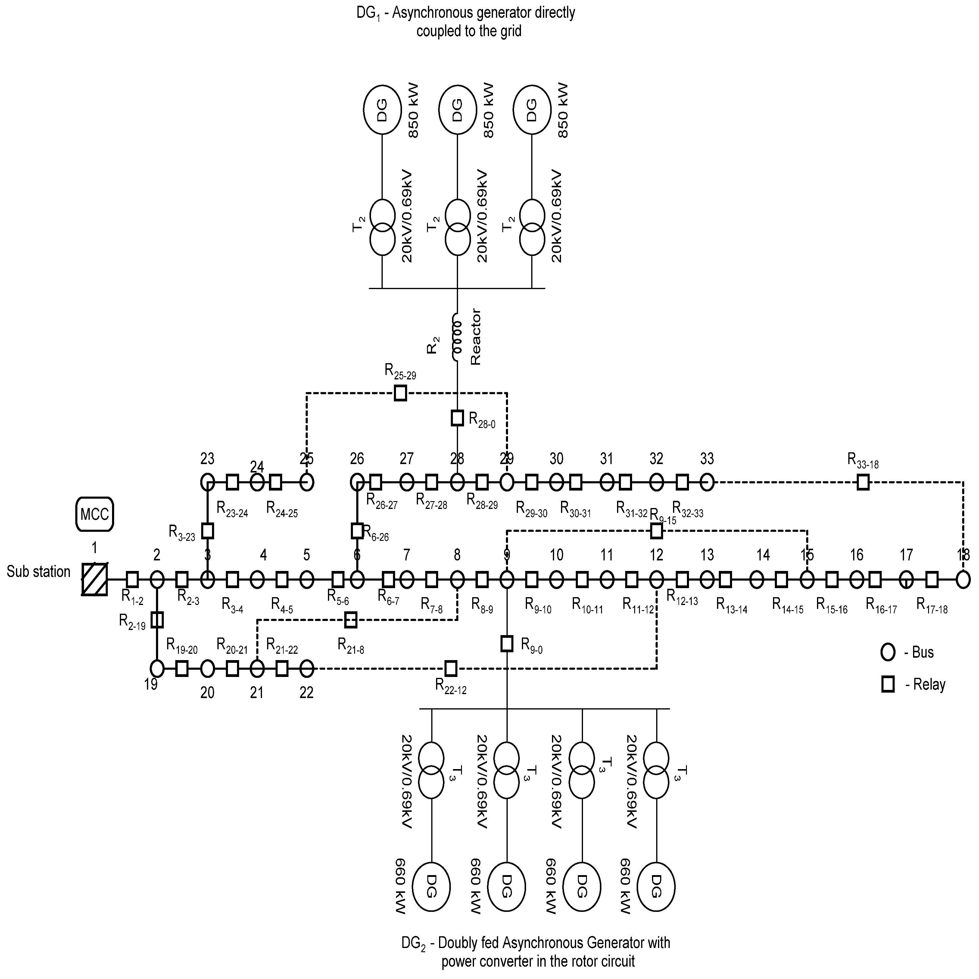
The proposed algorithm for a microgrid is constructed based on the IEEE 33 bus distribution system [57] with tie links [58,59,60] and DGs located at the specified locations as shown in Figure 2. The proposed network is assumed to be operating at 20 kV with a short circuit power of 500 MVA. The buses are assumed to be located at a distance of 1 km.
In the proposed microgrid structure, loads are devised with fuses, and DGs and feeders are devised with over current relays. The MCC is an additional storage module assumed to be located at the substation with essential software module for processing. When offline, for all possible configurations, MCC stores normal operating current, minimum fault current and maximum fault current, as shown by each relay in the lookup table (Figure 3). The fault level for each rth relay is determined as the ratio between current through rth relay and minimum pick-up current of rth relay. The minimum pick-up current is calculated as 1.5 times the overload current. The overload current is calculated as 1.25 times the normal operating current [61]. The normal operating current is determined based on Newton Raphson load flow. The fault current modeling for microgrid is carried out based on the procedure suggested by Thekla [62]. The fault current is determined as the ratio of the equivalent voltage source at the faulted point to the equivalent short circuit impedance at the faulted point.
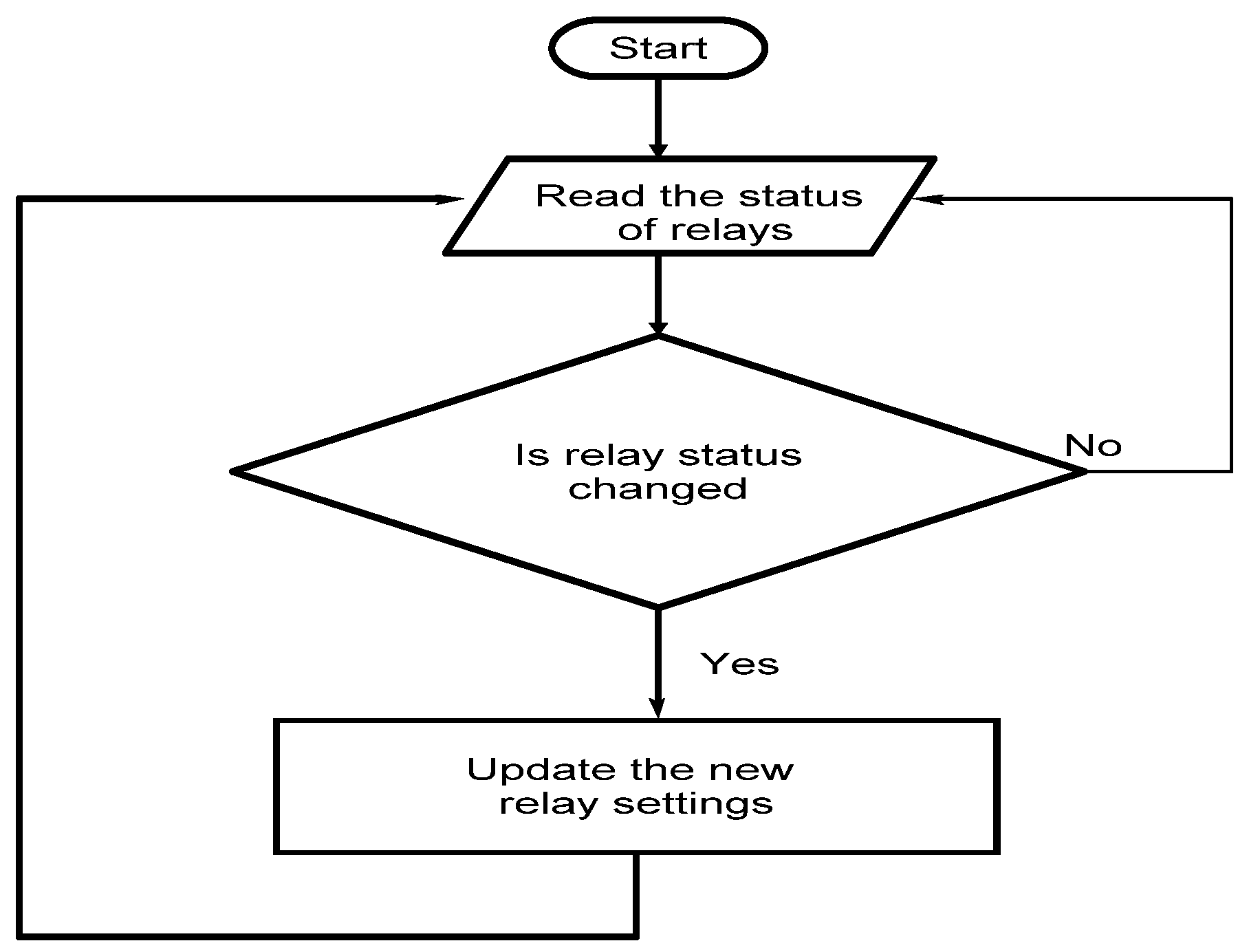
When online, MCC continuously tracks the relay status and current flowing through it. The change in status of the relay indicates a change in the configuration of the microgrid. For any change in status of any one of the relays (change in configuration), the MCC revises the relay settings (minimum pick-up current and fault level), with the settings being calculated and stored in MCC for the respective configuration. Thus, the proposed algorithm adapts the relay setting dynamically based on the configuration of the network over time. The procedural steps for updating protection settings in the microgrid are shown in Figure 4. Only three phase faults are considered for this study.
For a fault in the system, the primary relay associated with the fault meets the setting; hence, it is immediately opened. Meanwhile, the MCC identifies the occurrence of the fault since a set of relays indicates a current greater than that of pick-up. Hence, it verifies Kirchhoff’s Current Law (KCL) in each node and determines the faulted node and the associated relay based on the mapping table (Section 3.2). If the primary relay fails, then backup relays will be opened in sequence as explained in Section 3.2.

3.1. Identification of Faulted Bus Using MCC

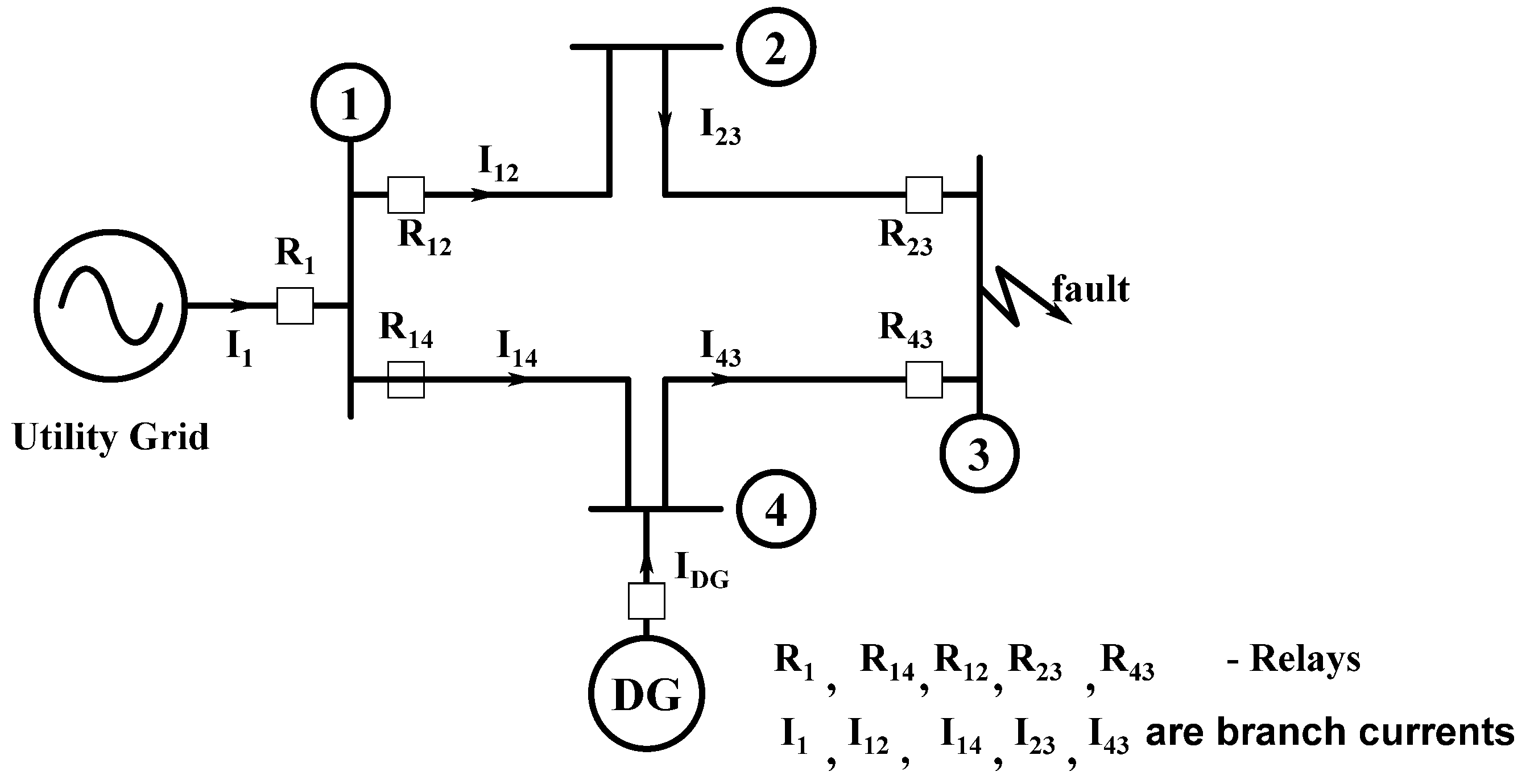
The identification of the faulted bus, primary relay and secondary relay using MCC is detailed with a sample network shown in Figure 5. For a fault in bus 3, both the utility and DG feed the fault. The utility feeds the fault through R1-R12-R23 and R1-R14-R43. The relay associated with the faulted bus meets the relay settings; hence, it is tripped. Meanwhile, MCC executes KCL at all the buses (here, bus 1, bus 2, bus 3 and bus 4) as I1 + I12 + I14, I12 + I23, I43 + I23 and IDG + I14 + I43, respectively, in order to precisely locate the faulted bus. KCL is verified with all the buses (1, 2 and 4 show the sum of currents as zero) except the faulted bus. Thus, MCC locates the faulted bus.
MCC verifies the status of the relays. If the primary relay fails to trip, then the secondary relay will be issued with trip message by the MCC after 200 ms based on the mapping table, which is explained in detail in Section 3.2.

3.2. Microgrid Central Relay Coordination Algorithm

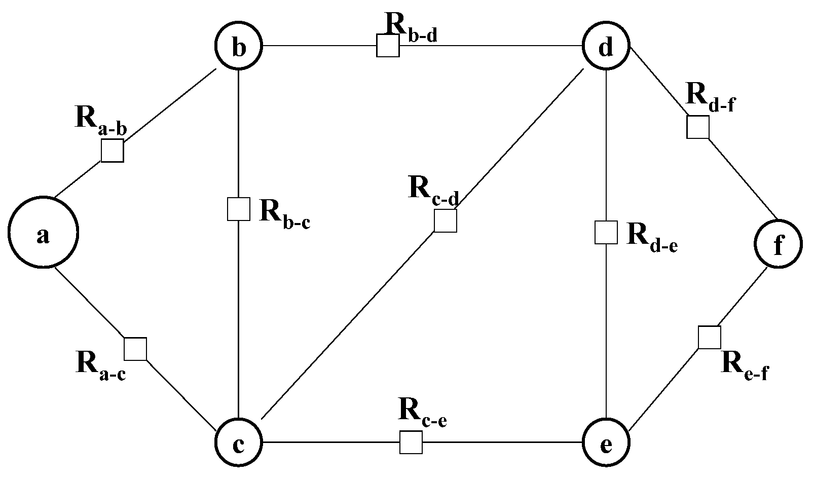
The microgrid central relay coordination algorithm is explained with the sample network (shown in Figure 6). The network has six nodes and nine edges. The line in the power system network is represented as edges, and buses in the power system network as nodes. One relay is connected to each line. The buses are named a, b, c, d, e, f and the relays connected between the nodes are represented with Ra-b, Rb-c, Ra-c, Rb-d, Rc-d, Rc-e, Rd-e, Rd-f, Re-f, respectively. The mapping table is created by the MCC by tabulating all the nodes’ (buses) row-wise and all the relays column-wise. ‘1’ is used to represent the link between the relay and the node and ‘0’ is used to represent no link between the relay and the node. The mapping between bus and relays is shown in Table 1 assuming that all the relays are in ON state.
The procedure for protection and relay coordination in the microgrid is detailed below in Section 3.2.1.

3.2.1. Protection and Relay Coordination Algorithm

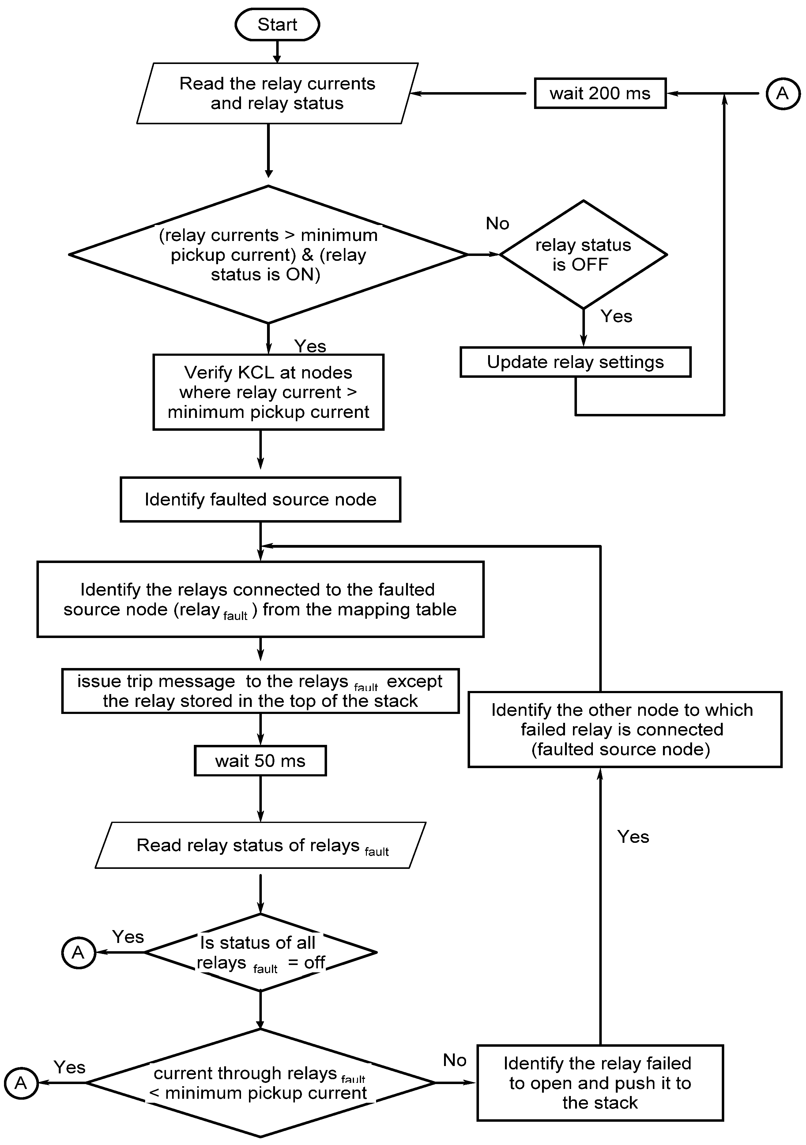
The flowchart for the protection and relay coordination algorithm for the microgrid is shown in Figure 7. It is assumed that a fault has occurred in node b (Figure 6). As discussed earlier, the primary relay opens immediately after the occurrence of fault since it meets its setting. Meanwhile, MCC also identifies the fault location (node b) based on KCL and denotes the faulted node as the faulted source node. It stores the faulted source node (node b) in a variable (here, it is named faulted node sequence). Once the fault is identified, MCC does the following:
1. It identifies the relay associated with the faulted source node (relaysfault) from the mapping table (Ra-b, Rb-c, Rb-d) and issues a trip message to the relaysfault except the relay stored in the top of the stack.
2. Every 50 ms
Monitors the current through the relays associated with the
faulted source node (Relaysfault = Ra-b, Rb-c, Rb-d) and its status.
If (status of Relaysfault is found to be open)
Exit the loop.
else
Determine the current through the associated relay.
If (current through Relaysfault< minimum pick-up current)
Exit loop.
else
(i).
Push relay that fails to open (assume Rb-c) into stack.
(ii).
From the mapping table, MCC determines the adjacent relay (Table 1) of failed relay. In this case, Rb-c is the failed relay. From the mapping table, Rb-c is connected between node b and c. MCC discards the node (b), which is already stored in faulted node sequence, and denotes the other node (c) as faulted source node.
With the new faulted node sequence (c), the same procedure as described above is repeated from step 1 until it exits the loop.

3.2.2. Results and Discussion

The proposed relay coordination algorithm is tested in matlab by inserting a fault in various buses for the microgrid (shown in Figure 2). The result for the fault in bus 16 is shown in Table 2.
As discussed earlier, the fault level through each individual relay for a fault associated with it is stored in the MCC. Additionally, for each change in configuration, the MCC updates this setting. Thus, for a fault in bus 16, the relay R15-16 meets its setting (fault level 82.19) and hence it is opened. Meanwhile, MCC also identifies the presence of a fault at bus 16 by verifying KCL and stores it as a faulted node sequence. The time taken for the execution of KCL is 21 ms.
Based on the adjacency matrix, MCC determines the relays associated with faulted bus (bus 16) as R15-16, R16-17 and issues a trip message to it. Then, MCC checks the status of the relays R15-16, R16-17. If the status of the relays R15-16, R16-17 is opened, then faulty part is isolated and the algorithm is stopped. In case of failure of any one of the relays (let it be R16-17), MCC checks the current through the associated relays (R15-16 and R16-17) and detects the failed relay (R16-17) since the current through the failed relay (R16-17) is greater than the pick-up current. Hence, MCC considers R16-17 to be failed relay and stores it in stack. Now MCC identifies the other node of R16-17 as 17 by discarding the node in faulted node sequence (bus 16). The new faulted node is bus 17 and it is stored in the faulted node sequence. Then, it identifies the associated relays of bus 17 as R16-17 and R17-18. Since R16-17 is on the top of the stack, it is discarded. Now MCC issues trip message only to R17-18. Thus, the protection and relay coordination is maintained by the MCC.
The proposed microgrid protection and coordination algorithm is verified (for fault at bus 16) with and without DG. The results for the same are presented in Table 2. For a high-impedance fault, the fault level through R15-16 was 12.495 (with DG) and 12.191 (without) DG, which is less than the relay setting (82.19). Hence, the relay will not open based on the local setting. However, MCC identified the fault in bus 16 by verifying KCL and the associated relays as R15-16, R16-17. Then, it gave a trip message to R15-16 and R16-17 based on the microgrid central relay coordination algorithm, thereby isolating the faulty part. Thus, the proposed algorithm works well even for high-impedance fault.

4. Performance Measures

In general, a proper protection scheme should pose major qualities such as speed of operation, sensitivity, reliability and selectivity. In the proposed algorithm, the primary relay opens immediately after the occurrence of the fault since those relays meet its settings. The settings for the relays are dictated by MCC for every change in status of the network. The relay setting will be given by MCC to respective relays well before the occurrence of fault. Hence, the communication speed will not affect the speed of operation of primary relays. However, the communication speed has an impact on the operation of secondary relays and on primary relays in case of high-impedance fault. Hence, a performance analysis of the communication network is carried out as follows.

4.1. Speed of Operation

As discussed above, any protection scheme should be fast enough to identify the fault and isolate a minimum faulty part. If not, it leads to significant damages to equipment and instability to the network. However, designing an accurate algorithm for protection consumes a considerable amount of time. The accuracy of protection algorithm and time of operation is inversely proportional to each other. Hence, a compromise is to be obtained between the time of operation and the accuracy [63].
Here, an attempt is made to find the speed of operation of the proposed protection scheme. The communication delay [64] includes transmission, propagation, queuing and processing delay. The maximum communication delay that can occur for the proposed microgrid network [65,66,67] is given as follows:
Maximum   communication   delay   =   M a x i = 1 33 ( T i t r a + T i p r o + T i q u e + T i p r c )
where Titra is the transmission delay for ith node, Tipro is the propagation delay for ith node, Tique is the queuing delay for ith node and Tiprc is the processing delay for ith node. The maximum communication delay is determined based on the assumptions [65,67] that the size of packet is 1 kb, the bandwidth of the communication link is 100 Mbps and optical fiber is used as the communication network.
(a) Transmission and propagation delay
The delay caused due to the bandwidth of the communication channel is called the transmission delay and it that which is caused due to the type of transmission medium is called the propagation delay. Transmission delay is determined as the ratio between the size of the data packet to link the bandwidth.
Transmission   delay = date   packet   Size link   bandwidth = 1 × 10 3 100 × 10 6 = 0.01   ms
Propagation delay is determined as the ratio between the distance travelled to the signal speed. The speed of the transmitting signal (fiber optics) is less than the speed of light and is assumed to 70% of the speed of light [65]. In the study microgrid considered for the study (Figure 2), node 18 is the farthest node from MCC. In this study, the distance between any two node is assumed to be 1 km. The farthest relay (R17-18), which is located between node 17 and 18, is considered to be 17.5 km away from the substation. Thus,
Propagation   delay = d i s tan c e   b e t w e e n    s o u r c e    a n d    d e s t i n a t i o n S p e e d    o f    t h e    s i g n a l = 17.5 × 10 3 0.7 × 3 × 10 8 = 0.833   µ s
(b) Processing delay and queuing delay
Processing delay is defined as the time taken for encoding/decoding the data, switching data from/into the communication channel, authenticating the data, sampling the rate and routing the algorithm. Processing delay is considered to be 100 µs [68]. Queuing delay is defined as duration of time for which the packet waits in transmitting device to be forwarded through the link. Since the dedicated channel is offered for communication, the queuing delay may be neglected. Thus, from Equation (2), the following can be obtained:
maximum possible communication delay = 0.01 ms + 0.833 µs +100 µs = 0.010933 ms

4.2. Sensitivity

Sensitivity refers to the accuracy involved in the identification of fault for various fault resistances. That is, the algorithm should be capable of protecting the system even for a minor fault. Additionally, the algorithm should not be triggered by an external fault. As per the suggested algorithm, the faulted bus is identified by both the over current concept locally and the differential concept centrally. For a fault in bus 16 (shown in Table 2) the relay R15-16 met its local setting (fault level); hence, it was tripped. Meanwhile, the MCC also identified the presence of fault in bus 16 by verifying KCL and issued a trip message to the relays associated with bus 16 (R15-16, R16-17). For high-impedance fault, the relay R15-16 did not meet its set value; however, the fault was identified by MCC since KCL was not satisfied with bus 16. Then, MCC issued a trip message to the relays associated with bus 16 (R15-16, R16-17). Thus, the proposed protection scheme is very sensitive irrespective of fault resistances and the severity of the fault.

4.3. Reliability

Reliability involves dependability and security. Dependability refers to tripping the relays when required and not tripping when not required. In the proposed algorithm, the local relay meets its setting only under faulted conditions; therefore, dependability is ensured. Additionally, in the proposed algorithm, dedicated communication lines are used for transmitting data between relay and MCC; therefore, security is ensured.

4.4. Selectivity

Selectivity refers to the detection of fault and isolation of a minimum faulty part. If the primary protection fails, then backup protection should be operated. As per the proposed scheme, for a fault in a bus, the lines associated with that bus (minimum faulty part) are tripped alone, i.e., for a fault in bus 16, as per the proposed algorithm, the faulted bus is identified both locally and centrally and then a trip message is issued to the associated relays (R15-16, R16-17), thereby isolating a minimum faulty part. In case the primary protection scheme fails, then back up relays (relays close to the primary relay) are opened according to the microgrid central protection and relay co-ordination algorithm, which ensures better selectivity.

5. Comparison and Performance Analysis

In reference [56], the sequence of operation of relays is carried out based on the shortest path from faulted point to nearest source. If same technique is applied to proposed network shown in Figure 2, then for a fault in bus 16 DG located at bus 9 (DG9) forms the nearest source. Therefore, shortest route from bus 16 to DG9 is R15-16 and R9-15. If the primary relay R15-16 fails to open, then as per prims aided Dijikstra algorithm, R9-15 is opened. The drawback faced with this is, even though backup relay (R9-15) is opened, fault will be fed by main grid and DGs through the alternate paths [69] (i) R17-18, R16-17 (ii) R14-15, R15-16.
Additionally, for a fault in bus 16, if both the relays R15-16 and R9-15 fails to open, then no further opening of relay occurs since coordination is maintained through shortest path from faulted point (bus 16) to nearest source (bus 9). This leads to severe damage to entire network. This cannot be accepted.
However, in the proposed algorithm, for any fault, the relay associated with the faulted bus is tripped. The further opening intimation is given to the relays associated with the failed node based on the mapping table. Hence, the possibility of DGs and utility grid feeding the fault is avoided in the proposed algorithm. The comparision of the proposed work with existing work [56] is tabulated in Table 3.
The proposed relay coordination algorithm works faithfully for microgrids with radial and looped configuration. In the proposed work, the individual relays are allotted with fault level setting. At the same time, the fault location is determined by MCC by applying KCL for all the nodes in the microgrid. Thus even though the local relay fails to locate the fault due to presence of high fault impedance, the MCC identifies the fault accurately. Thus the proposed scheme has high selectivity and sensitivity.

6. Conclusions

The existing protection schemes fail with the microgrid due to the dynamic variations in the microgrid. Most of the topological-based adaptive algorithms suggested for microgrid work effectively only for radial microgrids. They also feed the fault current via a DG through an alternate path. However, the proposed algorithm suits both radial and looped microgrids and the same is simulated in matlab and verified in an IEEE 33 bus distribution network-based microgrid. The proposed algorithm also avoids DGs feeding the fault through an alternate path. In the proposed algorithm, the relay settings are dictated by MCC for every change in the topology, which is well before the occurrence of fault. Hence, the primary relay responds to a fault immediately. The coordination time interval between the relays is set as 200 ms. The maximum time taken for communicating the information between the MCC and relay is 0.01093 ms. Thus, there is no compromise in the speed of operation of relays. Moreover, in the proposed algorithm, the individual relays are given with fault level setting, mean time for any abnormality in the network, and the fault location is determined by the MCC using KCL for all the nodes in the microgrid. Hence, even though the local relay fails to identify the fault due to high-impedance fault, the MCC locates the fault accurately. Thus, the proposed scheme has high selectivity and sensitivity. Even if the primary relay fails, the proposed algorithm calculates the parameters to operate the relay proximity to the primary relay, thereby maintaining coordination in the network.

Author Contributions

Methodology, B.B.J.; Software, R.B.K.; Writing—original draft, B.B.J.; Supervision, R.P.R. All authors have read and agreed to the published version of the manuscript.

Funding

This research received no external funding.

Data Availability Statement

The data used in this study is available in references [57,62].

Conflicts of Interest

The authors declare no conflict of interest.

References

  1. Lasseter, B. Role of Distributed Generation in Reinforcing the Critical Electric Power Infrastructure—Microgrids. IEEE WM Panel 2001, 1, 146–149. [Google Scholar]
  2. Ackermann, T.; Andersonn, G.; Soder, L. Distributed Generation: A definition. Electr. Power Syst. Res. 2001, 57, 195–204. [Google Scholar] [CrossRef]
  3. Guerrero, J.M.; Blaabjerg, F.; Li, Y.W.; Mohamed, Y.A.R.I.; Salama, M.M. Introduction to the Special Section on Distributed Generation and Microgrids. IEEE Trans. Ind. Electron. 2012, 60, 1251–1253. [Google Scholar] [CrossRef]
  4. Marhaba, M.S.; Farhangi, S.; Iman-Eini, H.; Iravani, R. Reactive power sharing improvement of droop controlled DFIG wind turbines in a microgrid. IET Gener. Transm. Distrib. 2018, 12, 842–849. [Google Scholar] [CrossRef]
  5. Laverty, D.M.; Best, R.J.; Morrow, D.J. Loss of mains protection system by application of phasor measurement unit technology with experimentally assesed threshold settings. IET Gener. Transm. Distrib. 2015, 9, 146–153. [Google Scholar] [CrossRef] [Green Version]
  6. Brearley, B.J.; Prabu, R.R. A review on issues and approaches for microgrid protection. Renew. Sustain. Energy Rev. 2017, 67, 988–997. [Google Scholar] [CrossRef]
  7. Alexandre, O.; Antonio, F. Adaptive network protection in microgrids. Int. J. Distrib. Energy Resour. 2009, 4, 201–225. [Google Scholar]
  8. Sharaf, H.M.; Zeineldin, H.H.; El-Saadany, E. Protection Coordination for Microgrids With Grid-Connected and Islanded Capabilities Using Communication Assisted Dual Setting Directional Overcurrent Relays. IEEE Trans. Smart Grid 2018, 9, 143. [Google Scholar] [CrossRef]
  9. Che, L.; Khodaiyar, M.E.; Shahidehpour, M. Adaptive protection system for microgrid. IEEE Electrif. Mag. 2014, 2, 66–80. [Google Scholar] [CrossRef]
  10. Senarathna, T.S.S.; Hemapala, K.T.M.U. Review of adaptive protection methods for microgrids. AIMS Energy 2019, 7, 557–578. [Google Scholar] [CrossRef]
  11. Najy, W.K.A.; Zeineldin, H.H.; Woon, W.L. Optimal protection coordination for microgrids with grid-connected and islanded capability. IEEE Trans. Ind. Electron. 2013, 60, 1668–1677. [Google Scholar] [CrossRef]
  12. Ghanbari, T.; Farjah, E. Unidirectional fault current limiter: An efficient interface between the microgrid and main network. IEEE Trans. Power Syst. 2013, 28, 1591–1598. [Google Scholar] [CrossRef]
  13. Ihamäki, J. Integration of Microgrids into Electricity Distribution Networks. Master’s Thesis, Lappeenranta University of Technology, Lappeenranta, Finland, 2012. [Google Scholar]
  14. Ustun, T.S. Design and Development of a Communication-Assisted Microgrid Protection System. Ph.D Thesis, School of Engineering and Science, Faculty of Health, Engineering and Science, Victoria University,, Footscray, Australia, 2013. [Google Scholar]
  15. Laaksonen, H.J. Protection principles for future microgrids. IEEE Trans. Power Electron. 2010, 25, 2910–2918. [Google Scholar] [CrossRef]
  16. Ustun, T.S.; Ozansoy, C.; Zayegh, A. Fault current coefficient and time delay assignment for microgrid protection system with central protection unit. IEEE Trans. Power Syst. 2013, 28, 598–606. [Google Scholar] [CrossRef]
  17. Ustun, T.S.; Ozansoy, C.; Zayegh, A. Modeling of a centralized microgrid protection system and distributed energy resources according to IEC 61850-7-420. IEEE Trans. Power Syst. 2012, 27, 1560–1567. [Google Scholar] [CrossRef]
  18. Ustun, T.S.; Ozansoy, C.; Zayegh, A. Differential Protection of Microgrids with Central Protection Unit Support. In Proceedings of the IEEE 2013 Tencon—Spring, Sydney, NSW, Australia, 17–19 April 2013; pp. 15–19. [Google Scholar] [CrossRef]
  19. Etemadi, A.H.; Iravani, R. Overcurrent and overload protection of directly voltage-controlled distributed resources in a microgrid. IEEE Trans. Ind. Electron. 2013, 60, 5629–5638. [Google Scholar] [CrossRef]
  20. Zamani, M.A.; Yazdani, A.; Sidhu, T.S. A communication-assisted protection strategy for inverter-based medium-voltage microgrids. IEEE Trans. Smart Grid 2012, 3, 2088–2099. [Google Scholar] [CrossRef]
  21. Zamani, M.A.; Sidhu, T.S.; Yazdani, A. Investigations into the control and protection of an existing distribution network to operate as a microgrid: A case study. IEEE Trans. Ind. Electron. 2014, 61, 1904–1915. [Google Scholar] [CrossRef]
  22. Sortomme, E.; Ren, J.; Venkata, S.S. A Differential Zone Protection Scheme for Microgrids. In Proceedings of the 2013 IEEE Power & Energy Society General Meeting, Vancouver, BC, Canada, 21–25 July 2013; pp. 1–5. [Google Scholar] [CrossRef]
  23. Haron, A.R.; Mohamed, A.; Shareef, H. Coordination of Overcurrent, Directional and Differential Relays for the Protection of Microgrid System. Procedia Technol. 2013, 11, 366–373. [Google Scholar] [CrossRef] [Green Version]
  24. Nthontho, M.P.; Chowdhury, S.P.; Winberg, S.; Chowdhury, S. Protection of Domestic Solar Photovoltaic Based Microgrid. In Proceedings of the 11th IET International Conference on Developments in Power Systems Protection (DPSP 2012), Birmingham, UK, 23–26 April 2012. [Google Scholar] [CrossRef]
  25. Brahma, S.M.; Girgis, A.A. Development of Adaptive Protection Scheme for Distribution Systems With High Penetration of Distributed Generation. IEEE Trans. Power Deliv. 2004, 19, 56–63. [Google Scholar] [CrossRef]
  26. Tong, X.; Wang, X.; Wang, R.; Huang, F.; Dong, X.; Hopkinson, K.M.; Song, G. The Study of a Regional Decentralized Peer-to-Peer Negotiation-Based Wide-Area Backup Protection Multi-Agent System. IEEE Trans. Smart Grid 2013, 4, 1197–1206. [Google Scholar] [CrossRef]
  27. Maleki, M.G.; Javadi, H.; Khederzadeh, M.; Farajzadeh, S. An Adaptive and Decentralized Protection Scheme for Microgrid Protection. Preprints.org 2019, 2019070251. Available online: https://www.preprints.org/manuscript/201907.0251/v1 (accessed on 8 July 2022). [CrossRef] [Green Version]
  28. Lin, H.; Liu, C.; Guerrero, J.M.; Vasquez, J.C. Distance Protection for Microgrids in Distribution System. In Proceedings of the IECON 2015—41st Annual Conference of the IEEE Industrial Electronics Society, Yokohama, Japan, 9–12 November 2015; pp. 731–736. [Google Scholar] [CrossRef] [Green Version]
  29. Lin, H.; Guerrero, J.M.; Vasquez, J.C.; Liu, C. Adaptive Distance Protection for Microgrids. In Proceedings of the IECON 2015—41st Annual Conference of the IEEE Industrial Electronics Society, Yokohama, Japan, 9–12 November 2015; pp. 725–730. [Google Scholar] [CrossRef] [Green Version]
  30. Kar, S.; Samantaray, S.R. Time-frequency transform-based differential scheme for microgrid protection. IET Gener. Transm. Distrib. 2014, 8, 310–320. [Google Scholar] [CrossRef]
  31. Kar, S.; Samantaray, S.R. Combined S-Transform and Data-Mining Based Intelligent Micro-Grid Protection Scheme. In Proceedings of the 2014 Students Conference on Engineering and Systems, Allahabad, India, 28–30 May 2014; pp. 1–5. [Google Scholar] [CrossRef]
  32. Saleh, S.A.; Ahshan, R.; Abu-Khaizaran, M.S.; Alsayid, B.; Rahman, M.A. Implementing and testing d-q WPT-based digital protection for microgrid systems. IEEE Trans. Ind. Appl. 2014, 50, 2173–2185. [Google Scholar] [CrossRef]
  33. Saleh, S.A. Signature-coordinated digital multirelay protection for microgrid systems. IEEE Trans. Power Electron. 2014, 29, 4614–4623. [Google Scholar] [CrossRef]
  34. Janssen, P. Monitoring, Protection and Fault Location in Power Distribution Using System-Wide-Measurements. Ph.D Thesis, Université Libre de Bruxelles, Brussels, Belgium, 2014. [Google Scholar]
  35. Li, X.; Dysko, A.; Burt, G.M. Traveling wave-based protection scheme for inverter-dominated microgrid using mathematical morphology. IEEE Trans. Smart Grid. 2014, 5, 2211–2218. [Google Scholar] [CrossRef] [Green Version]
  36. Salehi, V.; Mohamed, A.; Mazloomzadeh, A.; Mohammed, O.A. Laboratory-based smart power system, part II: Control, monitoring, and protection. IEEE Trans. Smart Grid 2012, 3, 1405–1417. [Google Scholar] [CrossRef]
  37. Sun, Y.; Cai, Z.; Zhang, Z.; Guo, C.; Ma, G.; Han, Y. Coordinated Energy Scheduling of a distributed multi microgrid system based on multi agent decisions. Energies 2020, 13, 4077. [Google Scholar] [CrossRef]
  38. Colson, C.M.; Nehrir, M.H. A Review of Challenges to Real-Time Power Management of Microgrids. In Proceedings of the 2009 IEEE Power & Energy Society General Meeting, Calgary, AB, Canada, 26–30 July 2009. [Google Scholar] [CrossRef]
  39. Coury, D.V.; Thorp, J.S.; Hopkinson, K.M.; Birman, K.P. Agent Technology Applied to Adaptive Relay Setting for Multi Terminal Lines. In Proceedings of the 2000 Power Engineering Society Summer Meeting (Cat. No.00CH37134), Seattle, WA, USA, 16–20 July 2000; Available online: https://ieeexplore.ieee.org/document/867549 (accessed on 5 September 2022).
  40. Kulasekera, A.L. Multi Agent Based Control and Protection for an Inverter Based Microgrid. Ph.D. Thesis, University of Moratuwa, Moratuwa, Sri Lanka, 2012; pp. 12–13. [Google Scholar]
  41. Birla, D.; Maheshwari, R.P.; Gupta, H.O. Time-overcurrent relay coordination: A review. Int. J. Emerg. Electr. Power Syst. 2005, 2, 1–13. [Google Scholar] [CrossRef]
  42. Gupta, A.; Swathika, O.V.G.; Hemamalini, S. Optimum Coordination of Overcurrent Relays in Distribution Systems Using Big-M and Dual Simplex Methods. In Proceedings of the 2015 International Conference on Computational Intelligence and Communication Networks (CICN), Jabalpur, India, 12–14 December 2015; pp. 1540–1543. [Google Scholar] [CrossRef]
  43. Bedekar, P.P.; Bhide, S.R.; Kale, V.S. Determining optimum TMS and PS of overcurrent relays using linear programming technique. In Proceedings of the The 8th Electrical Engineering/Electronics, Computer, Telecommunications and Information Technology (ECTI) Association of Thailand—Conference 2011, Khon Kaen, Thailand, 17–19 May 2011; pp. 700–703. [Google Scholar] [CrossRef]
  44. Kida, A.A.; Gallego, L.A. Optimal Coordination of Overcurrent Relays Using Mixed Integer Linear Programming. IEEE Lat. Am. Trans. 2016, 14, 1289–1295. [Google Scholar] [CrossRef]
  45. Ibrahim, D.K.; El Zahab, E.E.D.A.; Mostafa, S.A.E.A. New coordination approach to minimize the number of re-adjusted relays when adding DGs in interconnected power systems with a minimum value of fault current limiter. Int. J. Electr. Power Energy Syst. 2017, 85, 32–41. [Google Scholar] [CrossRef]
  46. Mohammadi, R.; Abyaneh, H.A.; Rudsari, H.M.; Fathi, S.H.; Rastegar, H. Overcurrent relays coordination considering the priority of constraints. IEEE Trans. Power Deliv. 2011, 26, 1927–1938. [Google Scholar] [CrossRef]
  47. Shih, M.Y.; Salazar, C.A.C.; Enríquez, A.C. Adaptive directional overcurrent relay coordination using ant colony optimisation. IET Gener. Transm. Distrib. 2015, 9, 2040–2049. [Google Scholar] [CrossRef]
  48. Tripathi, J.M.; Malik, S.K. An adaptive protection coordination strategy utilizing user defined characteristics of DOCRs in a microgrid. Electr. Power Syst. Res. 2023, 214, 108900. [Google Scholar] [CrossRef]
  49. Saha, D.; Datta, A.; Das, P. Optimal coordination of directional overcurrent relays in power systems using symbiotic organism search optimisation technique. IET Gener. Transm. Distrib. 2016, 10, 2681–2688. [Google Scholar] [CrossRef]
  50. Alkaran, D.S.; Vatani, M.R.; Sanjari, M.J.; Gharehpetian, G.B.; Naderi, M.S. Optimal Overcurrent Relay Coordination in Interconnected Networks by Using Fuzzy-Based GA Method. IEEE Trans. Smart Grid 2018, 9, 3091–3101. [Google Scholar] [CrossRef] [Green Version]
  51. Tjahjono, A.; Anggriawan, D.O.; Faizin, A.K.; Priyadi, A.; Pujiantara, M.; Taufik, T.; Purnomo, M.H. Adaptive modified firefly algorithm for optimal coordination of overcurrent relays. IET Gener. Transm. Distrib. 2017, 11, 2575–2585. [Google Scholar] [CrossRef]
  52. Sampaio, F.C.; Tofoli, F.L.; Melo, L.S.; Barrosso, G.C.; Sampaio, R.F.; Leao, R.P.S. Smart Protection system for microgrids with grid connected and islanded capabilities based on adaptive algorithm. Energies 2023, 16, 2273. [Google Scholar] [CrossRef]
  53. Ates, Y.; Uzunoglu, M.; Karakas, A.; Boynuegri, A.R.; Nadar, A.; Dag, B. Implementation of adaptive relay coordination in distribution systems including distributed generation. J. Clean. Prod. 2016, 112, 2697–2705. [Google Scholar] [CrossRef]
  54. Singh, M.; Vishnuvardhan, T.; Srivani, S.G. Adaptive protection coordination scheme for power networks under penetration of distributed energy resources. IET Gener. Transm. Distrib. 2016, 10, 3919–3929. [Google Scholar] [CrossRef]
  55. Aatee-Kachoee, A.; Hashemi Dezaki, H.; Ketabi, A. Optimized adaptive protection coordination of microgrids by dual setting directional overcurrent relays considering different topologies based on limited independent relays setting groups. Electr. Power Syst. Res. 2023, 214, 10879. [Google Scholar] [CrossRef]
  56. Swathika, O.V.G.; Hemamalini, S. Prims-Aided Dijkstra Algorithm for Adaptive Protection in Microgrids. IEEE J. Emerg. Sel. Top. Power Electron. 2016, 4, 1279–1286. [Google Scholar] [CrossRef]
  57. Baran, M.E.; Wu, F.F. Network Reconfiguration in distribution systems for loss reduction and load balancing. IEEE Trans. Power Deliv. 1989, 4, 1401–1407. [Google Scholar] [CrossRef]
  58. Guan, W.; Tan, Y.; Zhang, H.; Song, J. Distribution system feeder reconfiguration considering different model of DG sources. J. Electr. Power Energy Syst. 2015, 68, 210–221. [Google Scholar] [CrossRef]
  59. Abdelaziz, M. Distribution network configuration using a genetic algorithm with varying population size. J. Electr. Power Energy Syst. 2017, 142, 9–11. [Google Scholar] [CrossRef]
  60. Rajaram, R.; Kumar, K.S.; Rajasekar, N. Power system reconfiguration in a radial distribution network for reducing losses and to improve voltage profile using modified plant growth simulation algorithm with Distributed Generation (DG). Energy Rep. 2015, 1, 116–122. [Google Scholar] [CrossRef] [Green Version]
  61. IEEE Std C37.230.2007; IEEE Guide for Protective Relay Applications to Distribution Lines. IEEE Power Engineering Society Sponsored by the Power System Relaying Committee: Piscataway, NJ, USA, 2008.
  62. Thekla, N.; Boutsika, A.; Stavros, A.; Papathanassiou, B. Short-circuit calculations in networks with distributed generation. Electr. Power Syst. Res. 2008, 78, 1181–1191. [Google Scholar]
  63. Altuve, H.J.; Zimmerman, K.; Tziouvaras, D. Maximizing Line Protection Reliability, Speed, and Sensitivity. In Proceedings of the 2016 69th Annual Conference for Protective Relay Engineers (CPRE 2016), Atlanta, GA, USA, 20–22 April 2016. [Google Scholar]
  64. Yang, B.; Katsaros, K.V.; Chai, W.K.; Pavlou, G. Cost-Efficient Low Latency Communication Infrastructure for Synchrophasor Applications in Smart Grids. IEEE Syst. J. 2018, 12, 948–958. [Google Scholar] [CrossRef]
  65. Kansal, P.; Bose, A. Bandwidth and Latency Requirements for Smart Transmission Grid Applications. IEEE Trans. Smart Grid 2012, 3, 1344–1352. [Google Scholar] [CrossRef]
  66. Lo, C.-H.; Ansari, N. Decentralized Controls and Communications for Autonomous Distribution Networks in Smart Grid. IEEE Trans. Smart Grid 2013, 4, 66–77. [Google Scholar] [CrossRef]
  67. Kansal, P.; Bose, A. Smart Grid Communication Requirements for the High Voltage Power System. In Proceedings of the 2011 IEEE Power and Energy Society General Meeting, Detroit, MI, USA, 24–28 July 2011; pp. 1–6. [Google Scholar]
  68. Padhi, L.; Kartikeya, S.; Sivalingam, K.M.; Sai, S.S. Multi-Path Routing in Optical WDM Networks: Even Versus Uneven Split Bandwidth Allocation. In Proceedings of the International Conference on Signal Processing and Communications (SPCOM), Bangalore, India, 18–21 July 2010. [Google Scholar]
  69. Brearley, B.J.; Prabu, R.R.; Bose, K.R.; Sankaranarayanan, V. Adaptive relay co-ordination scheme for radial microgrid. Int. J. Ambient. Energy 2022, 43, 2180–2193. [Google Scholar] [CrossRef]
Figure 1. Classification of microgrid protection scheme.
Energies 16 04820 g001
Figure 2. Microgrid under study.
Energies 16 04820 g002
Figure 3. Offline calculations in MCC.
Energies 16 04820 g003
Figure 4. Flowchart for updating relay settings.
Energies 16 04820 g004
Figure 5. Sample power system network.
Energies 16 04820 g005
Figure 6. Sample network.
Energies 16 04820 g006
Figure 7. Flowchart for the microgrid central protection and relay coordination algorithm.
Energies 16 04820 g007
Table 1. Mapping between the nodes and edges (relay adjacency matrix).
BusesRelays
Ra-bRa-cRb-cRb-dRc-dRc-e Rd-eRd-fRe-f
a110000000
b101100000
c011011000
d000110110
e000001101
f000000011
Table 2. Execution of microgrid central relay coordination algorithm by MCC.
Bus NoFrom Bus To BusPick-up Current [A]Fault Level (Local Relay Setting) Fault Level for Fault at Bus 16KCL Evaluation by MCC for Fault at Bus 16 [A] Fault Current for High-Impedance Fault at Bus 16
[A]
Fault Level for High-Impedance Fault at bus 16 KCL Evaluation by MCC for High-Impedance Fault at Bus 16 [A]Fault Current for High-Impedance Fault at Bus 16 (Without DG) [A]Fault Level for High-Impedance Fault at Bus 16 (Without DG)KCL Evaluation by MCC for High-Impedance Fault at Bus 16 (Without DG) [A]
11213798.6119.990416.3213.03804693.4220
22399.690.7017.380263.0802.64102982.9900
33462.92111.7515.880151.8732.41401732.7570
44565.9582.8015.150151.8732.30301732.6300
5566848.0814.690151.8732.23301732.5510
66723.64146.6134.610124.3735.26101385.8220
77834.6478.8123.620124.3733.59001383.9730
88973.134.6915.650173.9402.37901962.6750
991041.6150.964.56028.8380.6930220.5270
10101138.2851.424.96028.8380.7530220.5720
11111235.7147.665.31028.8380.8080220.6140
1212138.47205.64102.340131.76415.557013115.4350
1313145.07267.24170.970131.76425.989013125.7850
1414154.16252.64208.370131.76431.674013131.4260
15151625.2482.1982.190315.36412.495030812.1910
16161722.0364.9747.533121.6159.1747.225474.541617.322469.010
17171818.8965.8055.430159.1748.42601618.5390
1821941.17274.4524.600153.9483.73901724.1710
19192044.4185.4622.800153.9483.46701723.8670
20202148.0364.3121.080153.9483.20501723.5750
21212223.3125.3029.370104.0254.46501134.8510
2232344.46151.1016.520111.6562.51101252.8070
23232443.1290.3017.030111.6562.58901252.8940
24242547.3956.0515.500111.6562.35601252.6330
2562649.3589.913.72027.8780.5650370.7420
26262751.2775.983.58027.8780.5440370.7140
27272853.3544.513.44027.8780.5230370.6870
28282992.6120.623.44048.4270.5230370.3960
29293041.2682.5825.380159.1743.85801613.9100
30303114170.3674.790159.17411.370016111.5220
3131326.74319.60155.360159.17423.616016123.9330
32323310.33184.81101.360159.17415.409016115.6160
21828.7248.1311.45050.0051.7410592.0440
91531.6146.5538.220183.6585.81001775.5990
221227.3951.1724.980104.0253.79801134.1260
183313.99120.2474.850159.17411.378016111.5300
252962.534.6511.750111.6561.78601251.9970
Table 3. Comparision of existing work with proposed work.
S. NoParametersExisting Work
Reference [56]
Proposed Work
1Primary relay operating time Sum of execution time of fault detection algorithm (153 ms) and communication delay No time delay involved for normal faults since the local relay opens immediately.
For high-impedance fault the primary relay is opened only after receiving trip message from central controller. Thus for high-impedance fault operating time of primary relays is the Sum of execution time of fault detection algorithm i.e KCL (21 ms) and communication delay (0.010933 ms)
2Fault current elimination DGs feed the fault in alternate path.DGs do not feed the fault in alternate path.
3Algorithm is applicable forMicrogrid with radial configurationMicrogrid with radial and looped configuration
Disclaimer/Publisher’s Note: The statements, opinions and data contained in all publications are solely those of the individual author(s) and contributor(s) and not of MDPI and/or the editor(s). MDPI and/or the editor(s) disclaim responsibility for any injury to people or property resulting from any ideas, methods, instructions or products referred to in the content.