Abstract
This paper reports on the influence of a magnetic field on the dynamics of partial discharges (PDs) in two distinct configurations with respect to the mutual orientation of electric fields. The broad application areas include electrical insulation systems of both high-voltage grids and industrial network devices as well as emerging segments such as electric vehicles or more electric aircraft. Traditionally, PD measurements are only carried out in an electric field. In all current-carrying power equipment, magnetic fields are also superimposed onto electric ones, thus influencing partial discharge behavior. It has been observed that the interplay between electric and magnetic fields influences the dynamics of PDs; parallel and perpendicular mutual orientations were specifically investigated. The measurement technique allowed us to quantitively detect the effect of magnetic fields on PDs in a corona point–plane arrangement. The novel element presented in this article is a detection of PD intensity modulated by a magnetic field, with both perpendicular and parallel orientations with respect to electric one, and a quantitative visualization in the form of the time-sequence diagrams. The simulation of electron trajectories in the presence of electric and magnetic fields revealed the elongation of the pathways and differentiation of the charged particle propagation times. The perpendicularly oriented magnetic field led to a twisting effect, whereas the parallel alignment reflected the propagation along a helical trajectory. A slightly stronger PD intensity amplification effect was observed in the case of a parallel alignment of electric versus magnetic fields as compared with the perpendicular orientation. The presented results may contribute to PD measurement methodology in both electric and magnetic fields as well as a better understanding of the underlying physical mechanisms. The observed effect of the modulation of the magnetically based PD dynamics may be relevant for the insulation systems of power equipment.
1. Introduction
The tendency toward higher voltage levels can be observed in both power transmission and distribution as well as in emerging segments such as ground and air transportation [,,,,,,,]. This implies an adequate design of electrical insulation systems to withstand electrical stresses, and it concerns both AC and DC cases. In this study, the effect of the parallel and perpendicular interplay between magnetic and electric fields on partial discharges (PDs) (nowadays being one of the key indicators of high-voltage (HV) insulation quality) is reported. Classically, only the effect of an electric field has been taken into account in PD investigations, whereas the influence of a magnetic field has been neglected. However, all current-carrying devices are also simultaneously exposed to surrounding magnetic fields; this refers to the insulation systems of power grids, substations, transportation, and industrial network devices [,,,]. The most common types of discharges refer to either internal discharges in gaseous inclusions inside solid dielectrics, surface discharges, and discharges in insulating liquids or external corona [,,,,,,,,]. There are various methods for PD detection based on direct measurements, capacitive coupling, or radiometric methods at different radiofrequency bands, i.e., high frequency (HF), very high frequency (VHF), and ultrahigh frequency (UHF) [].
The streamer channels that propagate along electric field lines in the presence of a magnetic field develop along a modified trajectory due to the Lorentz force acting on the particles []. The experimental results reported in this study refer to the impact of a magnetic field on a corona in point–plane setup. The investigation of a magnetic field on DC corona discharges in a low vacuum was shown in Elabbas et al. [] and in an ultrahigh frequency (UHF) band in Bhangaonkar et al. []. It was demonstrated that the effect of a magnetic field on a discharge current was most significant with negative corona discharges rather than with positive ones, which was due to field coverage on an ionization zone []. The magnetic field effects on PDs have also been observed at an alternating voltage in voids, on treeing in epoxy, and on a corona [,,,,,]. The behaviour of corona discharge was explored in the wire-cylinder electrode configuration under the effect of a superimposed magnetic field in []. The contribution of a transverse magnetic field on the prebreakdown phenomena was attributed to the fact that the crossed magnetic field accelerates the electron motion. It was also observed that the inception voltage of a corona was greater in a positive corona without a magnetic field, whereas the opposite occurred in a crossed magnetic field. Investigations of a magnetic field’s impact on corona discharges in oil were presented in Murugesa et al. [] using fluorescent and UHF detection. The behavior of corona discharge in mineral oil under AC subjected to a magnetic field was analyzed in []. It was reported that the impact of the magnetic field shifted the dominating frequency of the UHF signal (0.9 GHz) toward the lower band (0.3 and 0.6 GHz). In addition, the presence of the magnetic field increased the magnitude of the parameters such as rise time, fall time, and pulse width of the fluorescence signal compared with the magnetic-field-free case. The operational conditions influencing the performance of the PD cable under a low or medium vacuum in the presence of a magnetic field were investigated in []. The tests were performed in the context of the cable exposure to the magnetic field in the lithography machines.
The presented results are based on corona configuration in air, however, the applications areas are very broad, on one side related to discharges resembling point–plane configurations and on the other side are applicable to the partial discharges occurring in voids or in delaminations, where the effects of a magnetic field will be also present []. For example, this phenomenon is important in the power devices of the transportation segment [], which work at low and medium voltage levels and are usually driven by power electrics converters. There is an observed continuous trend toward higher voltages in these applications. In addition, transportation power devices operate at high current, reaching even up to a few kA, particularly in solutions driven by power electronics, for example in the distribution grids of electric vehicles or magnetic-bearing drive systems.
The huge trend for offshore wind park installation is observed. Traditionally, it referred to fixed platforms, now more and more projects are referring to deep-sea floating platforms. In such an arrangement, the submarine cables transferring the high power are thus carrying very high currents and are exposed to various mechanical stresses such as swinging, stretching, or twisting. In such cases, delamination and voids are mostly considered with respect to electrical high-voltage insulation, and the most exposed are joints and accessories, where the highest number of failures is usually reported []. Another class of applications where high currents occur, and hence high magnetic fields, is superconducting generators and motors []. In the transportation segment, this group is extended by levitating high-speed trains, where the magnetic induction can reach the Tesla level []. In those units, the coexistence of high electric and magnetic fields may impact the partial discharges occurring inside the high-voltage insulation.
Previous research has reported on either the qualitative impact of a magnetic field on PDs or the effects occurring at a very high magnetic field [,,,,,,,,,,,,]. In this article, a rather low magnetic field was applied to investigate the early stages of the magnetic effects that may take place in power cables, motors, or generators or be caused by leakage flux in the insulation of power transformers.
The level of magnetic field induction can vary significantly in these applications. For example, stray leakage magnetic fields of up to 700 mT may be present in transformers []. Similarly, the leakage flux in high-frequency solid-state devices for traction or more electric aircraft applications may reach up to hundreds of mT []. In power cables, the perpendicular magnetic field up to 550 mT was analyzed in [] with respect to the influence on electrical treeing in XLPE (crosslinked polyethylene) insulation. In case of industrial motors, the magnetic field induction in airgaps can reach the Tesla level []. On the other end, the magnetic field present in the superconducting magnet insulation can be above even a few Teslas [].
The measurements presented in this paper enabled the detection of the influence of magnetic fields on partial discharges in a dedicated setup. The quantitative comparison of the effect of the interplay between parallel and perpendicular magnetic and electric fields on partial discharges is a novel contribution shown in this paper. Hence, the novel element presented in this article is a detection of PD intensity modulated by a magnetic field and a quantitative visualization in the form of the time-sequence diagrams. In particular, the experiments were carried out in a quite weak magnetic field in order to investigate PD behavior at the bottom-line magnetic field level, which may be present in electrical grids and power equipment, industrial devices, e-mobility or the aircraft segment.
2. Configuration of Electric and Magnetic Fields
The high-voltage insulation is exposed to magnetic fields in all current-carrying devices, for example cables, power transformers, motors, and generators. As reported in this paper, the interplay between electric E and magnetic B fields influences the dynamics and trajectories of the discharges in the air. The magnetic field in this paper is represented by vector B, called the magnetic flux density. In this way, the PD behavior is potentially modulated by the current flow in the conductors. The trajectories of the particles depend on the initial velocity vector ν and the mutual orientation of both fields. Without considering the collisions in air during the charge propagation under the superposition of the magnetic and electric fields (B and E), the individual charge was subjected to Lorentz force FL according to the following equation []:
where q is the particle charge, m the particle mass, and v the particle velocity.
A frequency fB of the charged (q) particle circular motion around the vector of the magnetic field induction B equals the following:
In the experiment, two modes of the mutual orientation of the B and E fields were investigated: the first one perpendicular and the second parallel. Assuming that the initial charge velocity vector ν is aligned with electric field vector E, the pattern of the cycloidal motion around the magnetic field vector was expected in the perpendicular case, whereas the resulting trajectory was helical in the case of the parallel alignment of the E and B vectors at a certain spatial distribution of velocity vector ν around this direction. In this case, only the perpendicular component of the velocity vector with respect to the magnetic field vector will cause a deflection force. Hence, if E and B are aligned along the z-axis in the rectangular coordinate system, the circular movement will occur in the x–y plane and the motion with an increasing pitch along the z-axis will be forced by electric field E according to the following equation []:
where t stands for time.
It should be noted that a relative ratio of the electric and magnetic forces acting on an electron in a magnetic field with an induction of tens of mT and at an electric field strength in the range of 10 kV/cm, taking the common value of the electron drift velocity, yields this ratio in the range of a few hundred [].
The electric field E point–plane configuration with superimposed perpendicular (B⊥) and parallel (B‖) orientations of magnetic field induction is shown in Figure 1. The distance between point and plane electrodes is denoted a. The radius of the tip of the HV electrode is r and the radius of the ionization zone ξ is marked as ri. The latter represents the region of electron collision ionization where the electric field is above the ionization field strength. The electric field strength in this setup at the end of the ionization zone is expressed according to equation []:
where: U—applied voltage, a—distance between electrodes, r—radius of point electrode, and ri—radius of ionization zone.
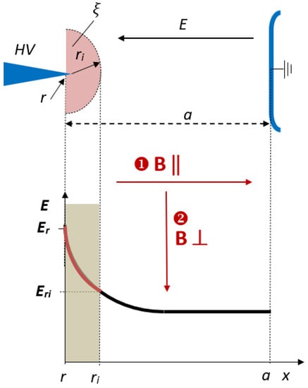
Figure 1.
Point–plane HV arrangement and distribution of electric field strength with marked ionization zone; a—distance between electrodes, r—radius of point electrode, ri—radius of ionization zone, B—induction of magnetic field, E—electric field, ξ—ionization region from point electrode, Er—electric field strength on the tip of HV electrode, and Eri—electric field strength at the end of ionization zone.
The orientation of the magnetic field induction vector B can assume two mutual arrangements with respect to the electric field vector E, i.e., perpendicular (B⊥) and parallel (B‖). In this paper, the effect of these two patterns on partial discharges is investigated. The ionization zone ξ, marked in Figure 1, is especially susceptible to the Lorentz deflection forces acting on charged particles. It refers to both electrons and ions moving in the interelectrode space. The residence time tr of the ions related to the drift between electrodes can be estimated from the expression []:
where μn denotes the mobility of the ion.
Assuming the mobility of the ion is equal to 10−4 m2V−1s−1, the interelectrode gap a = 40 mm, the radius of the tip of the HV electrode r = 0.7 mm, and the residence time corresponding to the voltage U = 9 kV yields approximately tr = 3.2 ms and for U = 20 kV is equal to tr = 1.4 ms.
3. Measurement Setup and Test Specimen
In this study, the results of the experiments that showed the effect of the interplay between parallel and perpendicular magnetic and electric fields on partial discharge dynamics are presented. The results presented in this article refer to the research that was performed in an original setup with a non-uniform electric field distribution. A weak parallel or perpendicular magnetic field was applied in order to detect partial discharges in a low-level field in power devices. The electrode configuration and measurement instrumentation are shown in Figure 2.
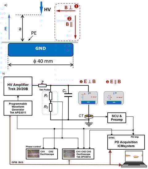
Figure 2.
Arrangement of (a) electrode configuration and orientations of electric field E and magnetic field B (perpendicular setup marked as ❶ and parallel as ❷); (b) instrumentation for partial discharge measurement with superimposed electric and magnetic fields. CT—current transformer, Cc—coupling capacitor, R1, R2—resistive divider, SCU—signal conditioning unit and preamplifier.
The electric field was created by the HV point and grounded plane arrangement, whereas the static magnetic field was formed by two permanent neodymium magnets that were positioned up–down with respect to the electrodes for parallel electric and magnetic field alignment and on both sides of the electrodes in the case of the perpendicular directions of both vectors. The magnetic field induction in the middle of the gap was equal to 60 mT. In the case with no magnets, the earth’s magnetic field is equal to ca. 50 μT. The measurement of the magnetic field induction was performed by means of an SMS 102 m with a Hall probe. The rather low magnetic field that was selected has already demonstrated an influence on the PD. It was intentional to point out that even such a weak field can modulate the PD dynamics. A stronger magnetic field will result in a more predominant effect. The copper HV needle electrode was positioned 40 mm above a grounded aluminum plane electrode with a diameter of 40 mm. The curvature of the HV point electrode was r = 700 μm. A 1 mm-thick polyethylene dielectric barrier with dimensions of 50 × 50 mm was placed on the ground electrode. In fact, the only reason for using this barrier was to avoid direct flashover from the point electrode to the ground. The sinusoidal voltage was delivered by a high-voltage source (Model Trek 20/20B) controlled by a programmable generator (Model Tektronix AFG 3011 Tetronix Inc., Beaverton, Oregon, USA).
For protection and filtering purposes, a resistor Z = 450 kΩ was connected at the output of the HV source. The partial discharges were acquired by means of a wide-band current transformer (CT) positioned in the specimen branch and terminated with 50 Ω.
The coupling capacitor Cc = 1100 pF was placed in a branch parallel to the sample, closing the high-frequency PD loop. The synchronization signal was taken from a TekProbe (Tektronix model P6015A), represented by a resistive divider R1 and R2, with an input impedance equal to 100 MΩ and an attenuation factor 1:1000. The PDs were acquired in the wideband phase-resolved mode (PRPD) using Power Diagnostix’s ICM system connected to a host computer using a GPIB interface []. The presented experiments were executed at room temperature (21 °C) at an atmospheric pressure of 0.1 MPa and a humidity level of 19%.
4. Experimental Results and Discussion
Recent research has revealed a quantitative dependence for PD dynamics (expressed as the number of discharges) on the applied magnetic field orientation with respect to an electric one. Two distinct cases were investigated, i.e., the parallel and perpendicular orientations of the E and B fields. The corresponding PRPD images that were acquired at 9 and 20 kV are shown in Figure 3.
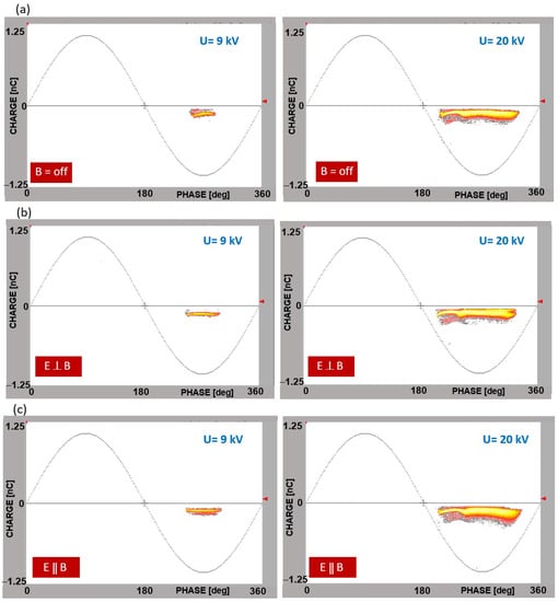
Figure 3.
PD patterns recorded at distinct voltage levels (9 kV—left column; 20 kV—right column) for the following field arrangements: (a) B = off; (b) E and B perpendicular; (c) E and B parallel.
The lower voltage level was above the inception voltage, whereas the higher one refers to the transition-level Trichel glow. The reference patterns shown in Figure 3a refer to the magnetic-field-free case. The superposition of the crossed perpendicular magnetic and electric fields is visualized in Figure 3b, whereas the interplay in the parallel alignment of these fields is shown in Figure 3c. The PD images are quite similar in the map view; however, one can notice the elongation of the pattern in the phase axis direction when comparing the reference magnetic-field-free case with the other ones. At the higher voltage (20 kV), the characteristic bending of the pattern indicated the proximity to the transition from the Trichel pulses to the pulseless phase that originated at the negative crest voltage.
The influence of the magnetic field was already noticed at the partial discharge inception voltage level, i.e., the voltage threshold was lower juxtaposed to the field free state. In turn, a lower inception level was measured in the case of a parallel electric and magnetic field configuration compared with a perpendicular arrangement. In those cases, the difference in the partial discharge inception voltage was about 10% and 8%, respectively, compared with the B = off stage.
The partial discharge phase profiles comparison between the magnetic-field-free case and the two arrangements with respect to the electric field orientation—parallel and perpendicular—is presented in Figure 4 (notice different scaling on the y-axis). Even at the lower voltage (9 kV), the waveshape of the comb at the crest level shows strong amplification at the crest value. The stronger effect for the parallel setup is also clearly visible. Similarly, this tendency is also observed at 20 kV, where a split into the two characteristic side peaks appears as the voltage is close to the transition to the corona pulseless form. The presence of a magnetic field distinctly increases the number of discharges, with a predominance for parallel alignment. For a more accurate measurement and quantification of this effect, the applied time transition diagrams, shown in the latter part, are very suitable.
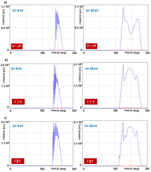
Figure 4.
PD phase profiles recorded at voltage levels (9 kV—left column; 20 kV—right column) for the following field arrangements: (a) B = off; (b) E and B perpendicular; (c) E and B parallel.
There may also be distinguished charge-related indicators. However, the experiments showed that the best “sensitivity” was achieved by comparing the number of discharges (called intensity), which is related to the physics of the discharges and the deflection of the pathway. Since the main idea of this paper was to compare the effect of both a parallel and a perpendicular magnetic field on PD, the PD intensity seems to be a very reliable and reproducible indicator. The superposition of the time sequence of the PD intensity profiles at a voltage level of 12 kV and an interelectrode distance of 40 mm for two cases of E and B interaction is presented in Figure 5. The initial reference level denotes the setup without a magnetic field; the two traces denote the intensity levels for the E and B perpendicular and parallel arrangements. The presence of the magnetic field resulted in an amplified intensity; in addition, the parallel orientation of the field vectors was elevated compared with the perpendicular orientation. N is the number of partial discharge pulses acquired within one minute, and ΔN reflects the difference between the number of pulses recorded when the magnetic field was turned on and off. The span that is denoted by ΔN- quantitatively reflects this influence, i.e., this equaled 900 for E ⊥ B and 1400 for E ‖ B.
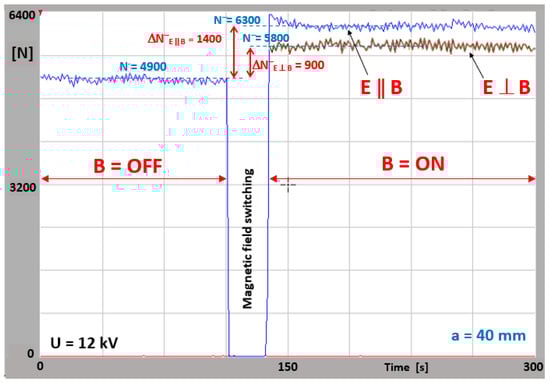
Figure 5.
Time sequence B = off/B = on (B—magnetic induction) of influence of magnetic field on PD intensity (N—number of discharges) in corona point–plain configuration for a tip-to-ground distance of a = 40 mm at voltages of 12 kV for parallel and perpendicular mutual orientations of E and B fields.
This example of the corona configuration indicates that the presence of a magnetic field leads to an amplification of the discharge channels. The influence of the magnetic field’s orientation on the PD dynamics is quantitatively shown in Table 1. The table contains the results of the voltage-dependent PD intensity (N- is the number of negative PD pulses that are unified to one minute) for the parallel and perpendicular orientations of the E and B fields. An illustration of the relationship between the number of negative polarity partial discharge pulses and the applied high voltage for both the magnetic-field-free and magnetic parallel- and perpendicular-oriented fields is shown in Figure 6. The number of discharges N- corresponds to a PD recording that lasted 60 s. The plot reveals the quasi-linear relationship between the number of corona discharges and the rising voltages over a broad range.

Table 1.
Voltage-dependent PD intensity (N−/min, in thousands) for parallel and perpendicular orientations of the E and B fields.
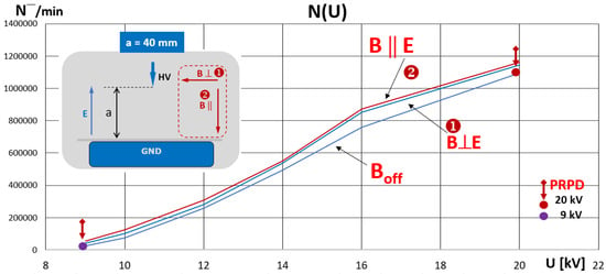
Figure 6.
Relationship between the number of negative polarity PD pulses and the applied voltage for both magnetic-field-free and magnetic-field-present conditions (with both ‖ and ⊥ alignment) in point–plane configuration.
The traces correspond to the B = off (black line) and B = on stages (‖—red; ⊥—blue). An important observation highlights the elevated PD dynamics during the presence of the magnetic field within the presented voltage range. In fact, the amplification for the parallel electric and magnetic field alignment was slightly higher than for the perpendicular case. On the graph, the lilac and red dots (9 and 20 kV, respectively) mark the correspondence to the PRPD patterns that are shown in Figure 3. The graphs clearly point out the impact of the magnetic field on the corona discharge dynamics (the span is smaller on the inception side and reaches its maximum level at 16 kV).
It should be underlined that the recorded pulses have a partial discharge origin. They appear when the high voltage is above the so-called PD inception voltage. There are also other necessary physical conditions necessary to trigger discharge. Therefore, the level of PD inception was clearly distinguishable in the presented measurement. Then, the PD magnitude is voltage dependent, and this effect was also recognized.
Thanks to the PD acquisition in a phase-resolved mode, the coherent phase position of individual PDs within a high-voltage period was observed. In the presented results, the partial discharge phase zones fit the right regions well, which also confirms that the recorded pulses are properly identified with PD. The phase location is especially evident for corona discharges. It was noticed that there was a very good signal-to-noise ratio while performing the acquisition, thus no treatment such as denoising was needed. The measurements were repeated several times and it should be stressed that the results regarding the corona in point–plane arrangement are very solid and repeatable. Hence, a statistical analysis was not performed directly; however, it should be mentioned that the phase-resolved PD acquisition intrinsically has an averaging mechanism built-in, due to the coherent superposition of several periods (e.g., at 50 Hz with 60 s measurement duration, there are 3000 periods acquired). The same refers to the time–intensity plots, where the individual measurement lasts for 300 s.
The underlying physical mechanism of the effect of the magnetic field on partial discharges is a convoluted problem and an actual research topic. To explain the impact on PD intensity, some hypotheses may be considered. The distinct polarities of positive ions and electrons result in deflections in opposite directions, leading to an extended free electron path between collisions. In this way, more high-energy electrons are causing an elevated rate of ionization. In addition, the deflection of positive ions promotes a free-electron path, decreasing the recombination rate. Hence, this effect will result in a higher number of partial discharges. The second aspect can be related to the lower corona inception voltage, which was noticed in both cases, i.e., in the experiments with parallel and perpendicular magnetic fields compared with the field-free case. Since the magnetic field component gives rise to an additional Lorentz force acting on the charged particles, a stronger electron acceleration will occur compared with a drift only in an electric field. The higher energy of the free electrons will enhance the ionizations of gas molecules, diminishing the PD inception voltage and resulting in an elevated number of discharges. The longer particle pathway also results in a longer beam propagation time in the interelectrode space and is especially important to electrons that trigger successive ionization events. As a consequence, a propagating streamer composed of ions and electrons will be influenced by a superimposed magnetic field.
The main intention of the research presented in this paper was to distinguish the effects on the parallel and perpendicular orientations of magnetic fields with respect to electric ones, and the impact was clearly distinguishable. It should be noticed that the only difference in the setup refers to the noninvasive switching of the magnetic field; therefore, the observed effects are attributed to this phenomenon.
5. Simulations
To analyze the origin of the investigated phenomena, simulations of the electron trajectories were employed in the joint electric and magnetic fields. The intention of the simulations was to compare a hypothetical particle flight path that resulted from the superposition of both electric and magnetic forces. Hence, no interplay between particles (e.g., collisions) were included in this study. Regarding the boundary conditions, the HV was put on the needle electrode and the plate electrode was placed on a ground potential. When a particle was in contact with a wall, the freeze option was assumed. The source of the electrons was located at the HV electrode, where the particle beam was at the tip (releasing 1000 particles in a simulation sequence). The initial condition assumed a mean kinetic energy at a level of 5 keV, with Gaussian standard deviation σ being equal to 0.1 eV. For a graphical visualization, the particle trajectory was rendered as a tube. The simulations were performed for a gap distance of a = 40 mm between the HV electrode and the ground side. The presented simulations were performed with DC voltage at an HV electrode at −16 kV. This simplification does not reflect those streamers that originated from the ionization in the airgap; however, it seems to be a good approximation for the sake of the visualization. Since the streamer moves along the electric field lines due to the ongoing ionization process, the key point was to analyze the impact of the path due to the magnetic field originated deflection. The simulated DC condition reflected a minuscule time slot on the sinusoidal waveform since the propagation time of the individual streamer was within nanoseconds. Motion Equation (1), which defined the Lorentz force that was acting on the charged particles, was solved in 3D geometry in the presence of electric and magnetic fields in the COMSOL Multiphysics environment []. Comparisons of the electron flaying paths at a high voltage of U = −16 kV are presented in Figure 7 for the magnetic-field-free case (Figure 7a), as well as for the two other scenarios with perpendicular and parallel magnetic fields (Figure 7b,c, respectively) with inductions equal to B = 60 mT in both cases. Without a magnetic field (B = 0 mT—Figure 7a), the electrons moved along straight lines from the conical beam source at the HV electrode tip. It can also be observed that a perpendicular magnetic field fostered the trajectories to twist and deflect (Figure 7b).
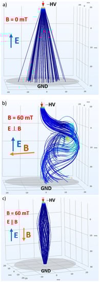
Figure 7.
Comparison of electron trajectories at a high voltage of U = −16 kV in (a) without a magnetic field and with a superimposed magnetic field with an induction B = 60 mT oriented as (b) perpendicular and (c) parallel with respect to electric field. Orientations of the E and B fields are shown in the graphs.
These trajectories resulted from the superposition of the circling effect of the beam around the magnetic field’s axis and the simultaneous drift due to the electric forward field toward the ground electrode. In the case of the applied parallel aligned magnetic field, the pathway was composed of a helical part due to a magnetic field with a pitch that was driven by an electric component. It is evident that the magnetic field influenced both the lengths of the entire trajectories as well as the charged particle propagation times. The trajectory length L of a curve r having the rx(t), ry(t), and rz(t) components can be calculated in the 3D space, in a time interval from t0 to te, according to the formula []:
Comparing the PD intensity effects from the measurement with the simulations from the trajectories, it turns out that the helically twisted effect caused more collisions and led to an amplified number of discharges.
The magnetic field deflection stimulated a modulation of the moving path as well as the propagation time between the high-voltage and ground electrodes. A summary of these values is shown in Table 2.
Table 2.
Electron beam propagation time tp (ns) in point–plane setup in various E × B orientations.
The simulations showed that both parallel and perpendicular electric and magnetic fields influence the path of the charged particle, leading to turbulences and the elongation of the electron beam trajectory. A certain relationship between the electric and magnetic forces in the perpendicular case may have even led to a wrapping of the original trajectory around the magnetic field axis, leading to the attenuation or even the termination of the discharge development. The superimposed presence of a magnetic field may result in a localized and focused discharge spot, not as dispersed as can be noticed in the field-free case. The effect of combined fields elongates the charge trajectories of both electrons and ions, resulting in an energy enhancement due to particle acceleration. In this way, the probability of ionization is increased, leading to an amplified discharge intensity that is also confirmed by the measurements in corona mode. It was observed that a longer pathway originated from the deflection due to the effective Lorentz force and also led to a prolonged beam propagation time compared with only being exposed to an electric field.
6. Conclusions
In conclusion, this paper presents the impact of a magnetic field on the dynamics of partial discharges. The measurements were carried out in a dedicated setup that allowed for sensitive detection in the presence of a weak magnetic field (unlike conventional PD measurements that are only carried out in an electric field).
The observed difference in PD intensity in the analyzed arrangement pinpoints the sensitivity of partial discharges to the presence of a magnetic field. A relatively low magnetic field (60 mT) has already demonstrated an influence on PD. It was intentional to pinpoint that even a rather weak field will modulate the PD dynamics. Thus, a stronger magnetic field will be more predominant. The magnetic field induction in the insulation of power devices in high-current-carrying equipment may be even at the Tesla level. In a real environment, in the insulation systems of, e.g., motors, power cables, and transformers, where the magnetic field may be much higher due to the current at the kA level (or magnetic structure of the devices), the interplay of both the electric and magnetic fields in the sources of partial discharges may additionally impact the dynamics and deterioration conditions of electrical insulation.
The measurement technique allowed us to detect the effect of magnetic fields on PDs in the corona mode. It was demonstrated that the interaction of electric and magnetic fields influences the dynamics of partial discharges in both the perpendicular and parallel configurations of these fields compared with the reference magnetic-field-free state. The visualization and determination of the quantitative influence of a magnetic field on PDs was performed by a combination of phase-resolved images and time-sequence intensity diagrams. It can be concluded that the number of discharges is well suited to study the effect of magnetic fields on PDs with high sensitivity.
Electron trajectories in the presence of electric and magnetic fields with either perpendicular or parallel orientations were also simulated. These revealed an elongation of the pathways and the differentiation of the charged particle propagation times. A perpendicularly oriented magnetic field led to a twisting effect, whereas a parallel alignment caused a propagation along a helical trajectory. The slightly stronger PD intensity amplification effect was observed in the case of a parallel alignment of the electric versus magnetic fields as compared with a perpendicular orientation. This observation leads to the conclusion that the length of the trajectory is not the only factor that has an impact on PD intensity. This seems to be one element, since in both cases when magnetic field was present, the PD intensity was elevated compared with the absence of a magnetic field. However, according to simulations, the trajectory of the charged particles in a perpendicular configuration is longer than in a parallel configuration, and the PD intensity from measurements is slightly higher in the latter case. The explanation of this effect could be related to the deflections in opposite directions of positive ions and electrons, which on one side result in an extended free-electron path between collisions and thus more high-energy electrons causing an increased rate of ionization, whereas the twisted but more focused trajectory in the parallel configuration results in stronger ionization compared with the increased spread in the perpendicular case. The lower corona inception voltage measured in both cases can be attributed to the additional Lorentz force yielding stronger electron acceleration and hence enhancing ionizations at lower voltages.
The obtained results stimulate future research to further reveal the physical mechanism of this phenomenon. The future work may also consider different configurations of electric- and magnetic-field alignments, as well as the behavior of PDs at much higher magnitudes of the magnetic field. In the case of simulations, in the next step the interplay between particles should be considered.
The presented study may contribute to a further understanding of the physical mechanisms of partial discharges exposed simultaneously to electric and magnetic fields. The effect of magnetically based PD dynamics modulation may be relevant for the insulation systems of various power devices.
Funding
This research received no external funding.
Data Availability Statement
Not applicable.
Acknowledgments
The author would like to thank Kazimierz Chudyba for his help with the magnetic setup arrangement.
Conflicts of Interest
The author declares no conflict of interest.
References
- Rajashekara, K. Power Conversion Technologies for Automotive and Aircraft Systems. IEEE Electrif. Mag. 2014, 6, 50–60. [Google Scholar] [CrossRef]
- Barzkar, A.; Ghassemi, M. Components of Electrical Power Systems in More and All-Electric Aircraft: A Review. IEEE Trans. Transp. Electrif. 2022, 8, 4037–4053. [Google Scholar] [CrossRef]
- Rumi, A.; Marinelli, J.G.; Seri, P.; Kohler, M.; Cavallini, A. Performance of corona resistant insulation for aerospace. Electr. Insul. Conf. (EIC) 2021, 22–25. [Google Scholar]
- Florkowski, M.; Błaszczyk, P.; Klimczak, P. Partial discharges in twisted-pair magnet wires subject to multilevel PWM pulses. IEEE Trans. Dielectr. Electr. Insul. 2017, 24, 2203–2210. [Google Scholar] [CrossRef]
- Shahsavarian, T.; Zhang, D.; McGinnis, P.; Walker, S.; Zhang, Z.; Cao, Y. Altitude Readiness of High-Voltage IGBTs Subjected to the Partial Discharge at Harsh Environmental Conditions for Hybrid Electric Aircraft Propulsion. IEEE Trans. Power Electron. 2022, 37, 3733–3736. [Google Scholar] [CrossRef]
- Xu, H.; Lowndes, R.; Cotton, I. Power Capacity of High Voltage Cables for Future Electrical Aircraft. In Proceedings of the Electrical Insulation Conference (EIC), Denver, CO, USA, 7–28 June 2021. [Google Scholar]
- Li, C.; Yang, Y.; Xu, G.; Zhou, Y.; Jia, M.; Zhong, S.; Gao, Y.; Park, C.; Liu, Q.; Wang, Y.; et al. Insulating materials for realising carbon neutrality: Opportunities, remaining issues and challenges. High Volt. 2022, 7, 610–632. [Google Scholar] [CrossRef]
- Florkowski, M. Effect of Magnetic Field on Partial Discharge Dynamics in Insulation Systems of Transportation Power Devices. IEEE Trans. Transp. Electrif. 2022, 8, 4678–4686. [Google Scholar] [CrossRef]
- Raether, H. Electron Avalanches and Breakdown of Gases; Butterworths: London, UK, 1964. [Google Scholar]
- Van Brunt, R.J.; Kulkarni, S.V. Method for measuring the stochastic properties of corona and partial—Discharge pulses. Rev. Sci. Instrum. 1989, 60, 3012–3023. [Google Scholar] [CrossRef]
- Li, C.; Shahsavarian, T.; Baferani, M.A.; Cao, Y. Tailoring insulation surface conductivity for surface partial discharge mitigation. Appl. Phys. Lett. 2011, 119, 032903. [Google Scholar] [CrossRef]
- Kojima, H.; Hotta, K.; Iwata, T.; Hayakawa, N.; Yanagita, N.; Kato, T.; Rokunohe, T.; Okubo, H. Influence of gap length on discharge channel propagation and breakdown mechanism in air. In Proceedings of the XVII International Symposium on High Voltage Engineering, Hannover, Germany, 22–26 August 2011. [Google Scholar]
- Florkowski, M. Classification of Partial Discharge Images Using Deep Convolutional Neural Networks. Energies 2020, 13, 5496. [Google Scholar] [CrossRef]
- Wang, K.; Yao, L.; Jahon, M.; Liu, J.; Gonzalez, M.; Liu, P.; Leung, V.; Zhang, X.; Ng, T.N. Ion-Exchange Separators Suppressing Self-Discharge in Polymeric Supercapacitors. ACS Energy Lett. 2020, 5, 3276–3284. [Google Scholar] [CrossRef]
- Florkowski, M. Imaging and simulations of positive surface and airborne streamers adjacent to dielectric material. Elsevier Meas. 2021, 186, 110170. [Google Scholar] [CrossRef]
- Rozga, P. Streamer Propagation and Breakdown in a Very Small Point-Insulating Plate Gap in Mineral Oil and Ester Liquids at Positive Lightning Impulse Voltage. Energies 2016, 9, 467. [Google Scholar] [CrossRef]
- Florkowski, M.; Krześniak, D.; Kuniewski, M.; Zydroń, P. Partial Discharge Imaging Correlated with Phase-Resolved Patterns in Non-Uniform Electric Fields with Various Dielectric Barrier Materials. Energies 2020, 13, 2676. [Google Scholar] [CrossRef]
- Kaziz, S.; Said, M.H.; Imburgia, A.; Maamer, B.; Flandre, D.; Romano, P.; Tounsi, F. Radiometric Partial Discharge Detection: A Review. Energies 2023, 16, 1978. [Google Scholar] [CrossRef]
- Manders, F.; Christianen, P.C.M.; Maan, J.C. Propagation of a streamer discharge in a magnetic field. J. Phys. D Appl. Phys. 2008, 41, 2340006. [Google Scholar] [CrossRef]
- Elabbas, K. Experimental study of magnetic field effect on dc corona discharge in low vacuum. J. Inst. Eng. India. Ser. B 2014, 95, 189–195. [Google Scholar] [CrossRef]
- Bhangaonkar, A.S.; Kulkarni, S.V.; Shevgaonkar, R.K. Study of the effects of alternating magnetic field on point-plane corona. IEEE Trans. Dielectr. Electr. Insul. 2011, 18, 1813. [Google Scholar] [CrossRef]
- Mi, J.; Xu, D.; Sun, Y.; Du, S.; Chen, Y. Influence of magnetic field on negative corona discharge currents. Elsevier J. Electrost. 2008, 66, 457–462. [Google Scholar] [CrossRef]
- Hepburn, D.M.; Steward, B.G.; Dissado, L.A.; Fothergill, J.C. Magnetic field disturbance of partial discharge activity in a cone-plane gap. In Proceedings of the Electrical Insulation Conference (EIC), Nashville, TN, USA, 24–27 September 2007. [Google Scholar]
- Reid, A.J.; Hepburn, D.M.; Stewart, B.G. The influence of external magnetic fields on the partial discharge characteristics of voids. Electr. Insul. Conf. 2013, 147–150. [Google Scholar]
- Du, B.X.; Su, J.G.; Han, T. Effects of magnetic field on electrical tree growth in silicone rubber under repetitive pulse voltage. IEEE Trans. Diel. Electr. Insul. 2015, 22, 1785–1792. [Google Scholar] [CrossRef]
- Wang, M.; Du, B.; Han, X.; Kong, X.; Li, Z. Effects of high magnetic field on partial discharge and flashover behavior of epoxy resin. IEEE Trans. Appl. Supercond. 2021, 31, 7700704. [Google Scholar] [CrossRef]
- Martinez-Tarifa, J.M.; Rivas-Conde, J.; Robles, G.; Sanz-Feito, J. Influence of leakage magnetic fields on partial discharge activity in power transformers. IEEE Trans. Diel. Electr. Insul. 2010, 17, 1724–1730. [Google Scholar] [CrossRef]
- Wang, M.Y.; Du, B.X.; Kong, X.X.; Li, Z.L.; Xiao, M.; Ma, Y.W. Effects of Gradient Magnetic Field on Charge Behavior and Electrical Tree Growth in Epoxy Resin. IEEE Trans. Dielectr. Electri. Insul. 2021, 28, 1686–1693. [Google Scholar] [CrossRef]
- Wais, S.I.; Mohammed, P.A. Influence of Magnetic Field on Characteristics of Corona Discharge in Wire-Cylinder Electrodes Configuration. Plasma 2021, 4, 764–779. [Google Scholar] [CrossRef]
- Murugesa, S.; Amalanathan, A.J.; Sarathi, R.; Srinivasan, B.; Samikannu, R. Investigation on Impact of Magnetic Field on the Corona Discharge Activity in Punga Oil Using Fluorescent Fiber and UHF Sensor Techniques. IEEE Access 2021, 9, 129218–129228. [Google Scholar] [CrossRef]
- Amizhtan, S.K.; Amalanathan, A.J.; Sarathi, R.; Edin, H.; Taylor, N. Impact of Magnetic Field on Corona Discharge Behavior of Mineral Oil under AC Voltage. IEEE Trans. Electr. Insul. 2022, 29, 1417–1424. [Google Scholar] [CrossRef]
- Driessen, A.B.J.M.; van Duivenbode, J.; Wouters, P.A.A.F. Operational conditions influencing the partial discharge performance of cables under low and medium vacuum. IEEE Trans. Diel. Electr. Insul. 2019, 26, 81–89. [Google Scholar] [CrossRef]
- Florkowski, M. Magnetic field modulated dynamics of partial discharges in defects of high voltage insulating materials. Nat. Sci. Rep. 2022, 12, 22048. [Google Scholar] [CrossRef]
- Lu, B.; Li, S.; Cui, Y.; Zhao, X.; Zhang, D.; Kang, Y.; Dong, H. Insulation Degradation Mechanism and Diagnosis Methods of Offshore Wind Power Cables: An Overview. Energies 2023, 16, 322. [Google Scholar] [CrossRef]
- Stryczewska, H.D.; Stępień, M.A.; Boiko, O. Plasma and Superconductivity for the Sustainable Development of Energy and the Environment. Energies 2022, 15, 4092. [Google Scholar] [CrossRef]
- Li, X.; Xu, W.; Liao, K.; Wu, X. Design of Stator-Magnet Moving-Iron Transverse-Flux Linear Oscillatory Machine Considering Asymmetric Saturation. IEEE Trans. Transp. Electrif. 2022, 8, 3464–3477. [Google Scholar] [CrossRef]
- Eslamian, M.; Kharezy, M.; Thiringer, T. An Accurate Method for Leakage Inductance Calculation of Shell-Type Multi Core-Segment Transformers With Circular Windings. IEEE Access 2021, 9, 111411–111437. [Google Scholar] [CrossRef]
- Gao, Y.; Du, B.X.; Ma, Z.L. Effect of Magnetic Field on Electrical Treeing Behavior in XLPE Cable Insulation. In Proceedings of 2011 International Symposium on Electrical Insulating Materials, Kyoto, Japan, 6–10 September 2011; pp. 457–461. [Google Scholar]
- Du, B.X.; Li, Y.M.; Wang, M.Y.; Liu, Z.X.; Han, X.T.; Zhang, Y.; Li, J.; Li, Z.L.; Sun, H.L. Effects of magnetic field on surface flashover of polyimide film for superconducting magnet insulation. In Proceedings of the 2020 IEEE 3rd International Conference on Dielectrics (ICD), Valencia, Spain, 5–31 July 2020; pp. 97–100. [Google Scholar]
- COMSOL Multiphysics Users Guide 6. 0. 2021. Available online: https://doc.comsol.com/6.0/doc/com.comsol.help.comsol/COMSOL_ReferenceManual.pdf (accessed on 21 January 2023).
- Arc Length in Space. Available online: https://math.libretexts.org/ (accessed on 21 January 2023).
Disclaimer/Publisher’s Note: The statements, opinions and data contained in all publications are solely those of the individual author(s) and contributor(s) and not of MDPI and/or the editor(s). MDPI and/or the editor(s) disclaim responsibility for any injury to people or property resulting from any ideas, methods, instructions or products referred to in the content. |
© 2023 by the author. Licensee MDPI, Basel, Switzerland. This article is an open access article distributed under the terms and conditions of the Creative Commons Attribution (CC BY) license (https://creativecommons.org/licenses/by/4.0/).