Abstract
The issue of converted voltage distortion by high-power converters at pulse-width modulation (PWM) with a low switching frequency of semiconductor modules is still relevant. Currently, the Programmed Pulse Pattern PWM (PPWM) technique is used extensively that allows pre-eliminating the selected harmonics from the converter’s voltage and current spectrum or reducing them to meet the voltage quality standard requirements. A review of scientific publications has shown the insufficiency of available studies on defining and estimating the impact of powerful converters with PPWM. The problem of defining the amplitudes of higher harmonics generated by a converter with PPWM, which are the main cause of electronic equipment failures at the common grid connection point, is particularly relevant. This study considers the behavior of the NPC converter voltage and current spectra at PPWM with the selected harmonic elimination (SHE) for three-level (3L) voltage waveforms. The behavior of up to the 50th non-eliminated harmonics in the NPC converter voltage and current spectra is first shown for a modulation factor changing within 0–1.15 at the pitch of 0.01 for six different SHE PPWM: no. 1–5 and 7; no. 2–5, 7, 11, and 13; no. 3–5, 7, 11, 13, 17, and 19; no. 4–5, 7, 11, 13, 17, 19, 23, and 25; no. 5–5, 7, 11, 13, 17, 19, 23, 25; 29, and 31; no. 6–5, 7, 11, 13, 17, 19, 23, 25, 29, 31, 35, and 37. The concept proposed herein allows measuring the current consumed amplitudes of NPC converter with SHE PPWM at the low average error of about 6%. The adequacy of the approach used herein to determine the current harmonic amplitudes has been experimentally verified with laboratory equipment. The results are consistent with engineering accuracy. The research work is promising for further study and estimation of the impact of the NPC converter SHE PPWM for more complex multi-pulse grid connection circuits and resonance phenomena.
1. Introduction
The use of power semiconductor converters in the fields of power systems, renewable energy, and powerful adjustable speed drives has expanded significantly in recent years. Efficient use of the converted power requires a reduction in the switching frequency of power converters, while the voltage and current waveforms must meet international power quality standards. This is not always possible to optimize, which is an important task for researchers in the field of power electronics.
DC/AC converters commonly feature pulse-width modulation (PWM) techniques with fixed pulse intervals within the reference carrier frequency. They include the well-known sinusoidal and space vector PWM techniques. However, there is an alternative PWM technique, where individual pulses are not limited to the reference carrier signal sampling time but may vary in width and position over the full converter voltage cycle within the set-up symmetry. The main harmonic of the converter-consumed current can be controlled by both changing the semiconductor module switching times and a phase shift between the source and the converter voltages. This technique is called Programmed Pulse Pattern PWM (PPWM) [1].
The PPWM technique was first introduced in the early 1960s, but it was not widely implemented in practice at the time since microprocessor technology was underdeveloped. When it emerged, this technique had a fundamental problem of finding the optimal pulse generation time to suppress or completely eliminate the selected harmonics defined by solving nonlinear transcendental equations. The optimal programmed pulse pattern means semiconductor module switching sequences calculated depending on the specified optimality criterion, minimizing power losses and/or distortion of voltage and current waveforms of the DC/AC converter [2,3,4].
To date, along with the two-level topology, multilevel ones are widely used in the field of power semiconductor converters. More complex DC/AC converter voltage waveforms (unipolar, bipolar, staircase, 2L, 3L, multi-L with both uniform and different levels, symmetric, asymmetric, etc.) are created using multilevel topologies. New topologies contributed to the development of the PPWM technique since the mathematical description of voltage waveforms became more complicated, and, consequently, the search for “optimal” switching patterns became more difficult. Currently, the literature describes two main approaches to the converter voltage spectra generation using PPWM: selected harmonic elimination (SHE) and selected harmonic suppression (SHS) [5].
SHE PPWM was first demonstrated in 1973 for a 2L voltage inverter. It was designed to gradually eliminate lower-order harmonics according to a given semiconductor module switch number. Herein, we will consider the SHE PPWM since it is used most frequently in practice [6,7,8].
The SHE PPWM technique was first implemented in 2007 for a 3L 150 kVA converter with clamped diodes. This approach is based on meeting voltage quality standards, particularly, the total harmonic distortion of the voltage (THDU%) and individual harmonic amplitudes. Currently, this technique is rarely used [9,10].
2. Overview of Studies and Problem Statement
Many semiconductor converter manufacturers use the SHE PPWM technique for high-power active front-end rectifiers (AFE) with a low switching frequency. Some studies also demonstrate the possibility of using this technique for voltage source inverters (VSI). For advertising purposes, manufacturers indicate the clean voltage and/or current spectra for up to the 40th or 50th harmonic. This allows reducing capital costs for compensation filters. However, in reality, a clean spectrum is possible only under certain, not always achievable conditions. Such conditions include operation exclusively in the rated mode with a given modulation factor, lack of resonance in the electrical circuit, and perfect synchronization with the voltage source.
In 2004, J. Pontt, J. Rodriguez, and R. Huerta published one of the earliest and most significant scientific papers [11] on studying and defining the converter voltage individual harmonic distortions at SHE PPWM. In this paper, the authors’ study was focused on estimating the impact of high-power AFEs on the grid with 6-pulse and 12-pulse connection circuits. It was the first to show a way to calculate the harmonic amplitudes of the converter voltage spectrum with high accuracy. However, the narrowly focused practical applicability of the study results does not allow the published materials to give a complete picture of the converter voltage and consumed current spectra up to the 50th harmonic over the entire modulation factor variation range. The paper provides an equation used to calculate the higher current harmonics; however, experimental studies of the current spectra are not given.
Other previous studies also demonstrate that at SHE PPWM, the converter voltage spectrum may vary significantly depending on the modulation factor. Studies [12,13,14,15,16] show the behavior of some non-eliminated harmonics when the modulation factor changes while not considering most of the equally important higher harmonics. Refs. [17,18,19,20,21,22] consider several SHE PPWMs with identical eliminated harmonics while showing how the spectrum and total harmonic distortion of the converter voltage may differ at the same modulation factors. However, these studies are too limited, and the spectra are only provided for a few certain modulation factors, which do not allow for their full estimation.
Recent studies [23,24,25,26,27,28] have focused on searching for optimal SHE PPWMs using advanced algorithms for solving non-linear equations. The results show an improved quality of the voltage and current spectra for individual modulation factors, but the impact of each individual non-eliminated harmonic over a wide modulation factor variation range was not analyzed in detail.
Some studies [29,30] consider searching for SHE PPWMs to bypass the resonance region of the grid impedance frequency response to improve the voltage quality at the connection point of industrial consumers to a common grid. However, the papers describe only experimental methods to estimate the impact of converters without preliminary calculation of the spectra of current induced by supply voltage distortions under the conditions of existing power grid modes.
Thus, a review of the scientific literature and the practice of implementing the authors’ research results to provide the electromagnetic compatibility of high-power AC drives with a grid at the industrial enterprises have shown that the SHE PPWM technique is very popular but understudied both in practice and in theory. The review has shown that the existing studies and the results of estimating the DC/AC converter voltage and current spectra behavior at SHE PPWM for three-level (3L) signal waveforms most common in the field of high power and low semiconductor module switching frequencies are insufficient. They do not allow estimating the behavior of each individual harmonic up to the 50th one in the voltage and current spectra for the possible converter operation over the full modulation factor variation range. The studies in the field are undoubtedly relevant and constitute the key objective hereof.
The paper is structured as follows. Section 1 is an introduction describing the topic of the study. Section 2 reviews the literature and formulates the study objective and problems. Section 3 is devoted to the mathematical description and search for SHE PPWMs for 3L voltage waveforms. Section 4 describes the calculation technique and estimates the NPC converter voltage and current spectra. Section 5 provides the results of checking the adequacy of the calculation results with full-scale measurements on laboratory equipment. Section 6 lists the basic conclusions of the study and prospects for further research.
3. Mathematical Description of the 3L Unipolar Voltage and the Search for SHE PPWMs
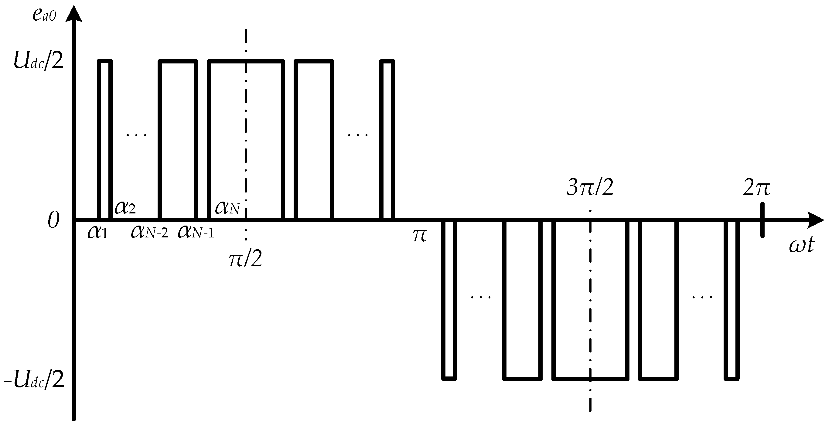
As Figure 1 shows, the 3L unipolar voltage may change an arbitrary number of times N per cycle at time instants αN.
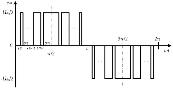
Figure 1.
3L Unipolar Voltage of Converter with PPWM.
If α1, α2, …, αN determine the N switching time instants, the shape of the pulse-width modulated converter voltage ea0(ωt) can be represented by the Fourier series [31]
where ω is the angular frequency; Udc is the DC voltage; n is the harmonic number; a0, an, and bn are the Fourier series coefficients (a0 = 0).
Considering quarter-wave symmetry
the Fourier series coefficients are defined as follows
Using the property of quarter-wave symmetry for an odd N number, the Fourier series coefficients will be
where k is the switching angle order number.
Substituting Equations (5) and (6) into (1), we obtain a mathematical equation to describe the 3L voltage waveform
Equations (5) and (6) form a system of equations with N unknown quantities. Therefore, the Fourier series harmonic components can be found at given αN values for any particular case.
The first harmonic amplitude at n = 1 from Equation (7) is
where the modulation factor can be defined as
Switching angles for SHE PPWM are obtained by solving a system of nonlinear transcendental equations with the number of unknown quantities equal to the number of harmonics to be eliminated, which is limited by the number of converter semiconductor module switches. The maximum number of switching angles N is defined as [31]
where fswave is the average switching frequency; f is the voltage frequency.
The number of eliminated harmonics q is defined by the formula
Based on Equations (8) and (9), the correlation between the switching angles and the converter voltage spectrum harmonic amplitudes is written as
where Enm is the nth harmonic amplitude; m is the modulation factor. The modulation factor variation range is 0 to 1 or 0 to 4/π, providing the first harmonic amplitude that varies from 0 to the maximum value.
The successful solution to the system of Equation (12) largely depends on defining the initial conditions (initial switching angles). They can be defined by the equation
where N is the number of switching angles; k is the switching angle order number; Δα is the initial mismatch of switching angles to achieve search results.
Table 1 shows the initial switching angles calculated for six SHE PPWMs most commonly used in practice under conditions of low switching frequency: no. 1–5 and 7; no. 2–5, 7, 11, and 13; no. 3–5, 7, 11, 13, 17, and 19; no. 4–5, 7, 11, 13, 17, 19, 23, and 25; no. 5–5, 7, 11, 13, 17, 19, 23, 25, 29, and 31; no. 6–5, 7, 11, 13, 17, 19, 23, 25, 29, 31, 35, and 37.

Table 1.
Initial switching angles for six SHE PPWMs.
To search for solutions to the system of Equation (12), an algorithm based on the particle swarm method (PSM) was applied. Algorithm description:
Step 1. Choosing particle swarm population size N = 25; choosing the particle swarm search space dimension D = 3…13 depending on the number of switching angles from α1 to αD; choosing initial conditions from Table 1; choosing the maximum number of iterations itermax = 125; choosing inertial weight ωmin = 0.2 and ωmax = 0.7; choosing weight coefficients c1 = 1.5 and c2 = 1.5; choosing search space boundaries to conduct random initialization of the position vector for each swarm particle from xmin = 0 to xmax = π/2; choosing the initial speed of each particle randomly from vmin = π/10 to vmax = −π/10; choosing the modulation factor m from 0 to 1.15 at a pitch of 0.01;
Step 2. Choosing the objective minimization function according to Equation (12) within the limits . An example of an objective function with unknown quantities α1, α2, α3 for SHE PPWM no. 1 is as follows:
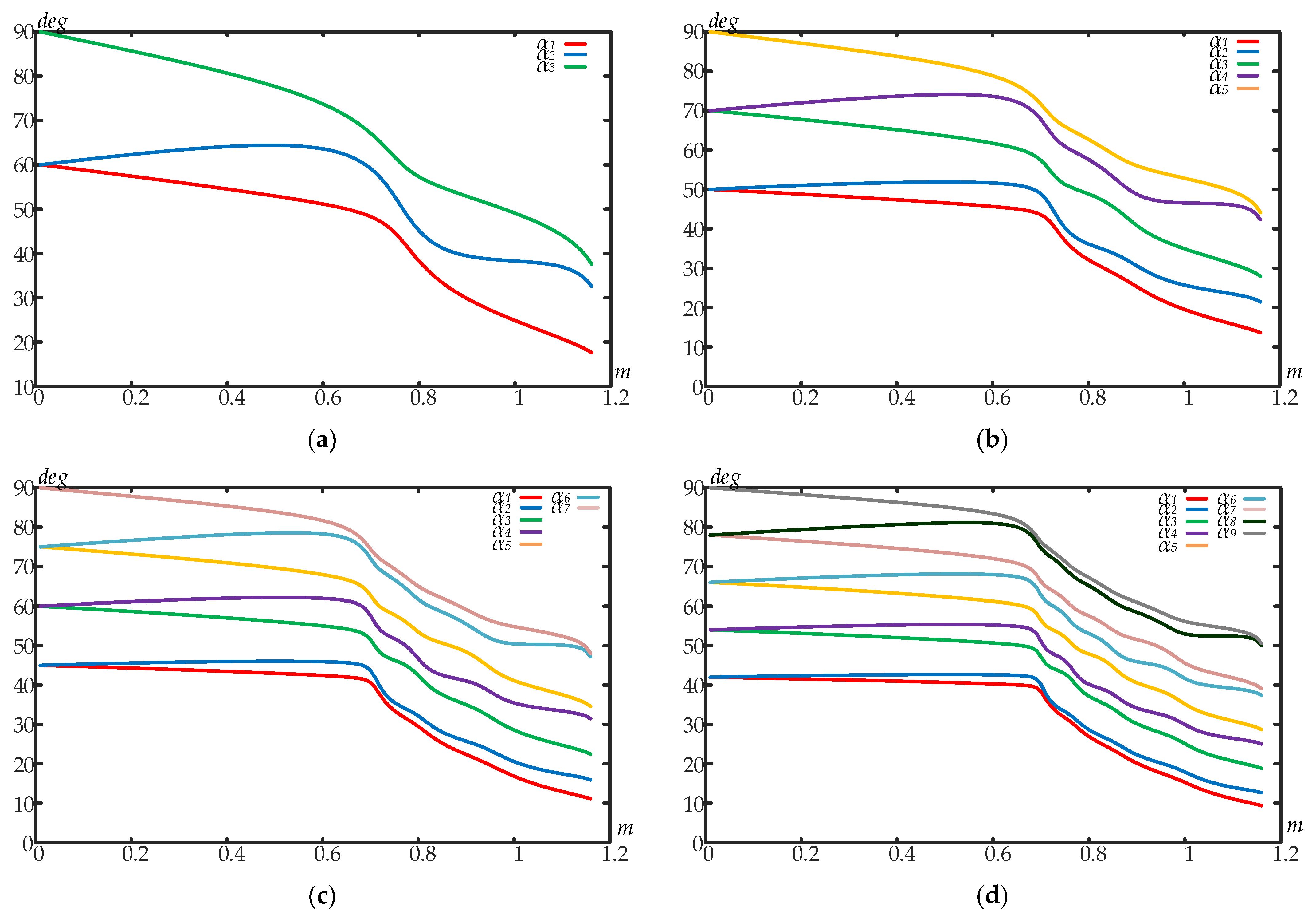
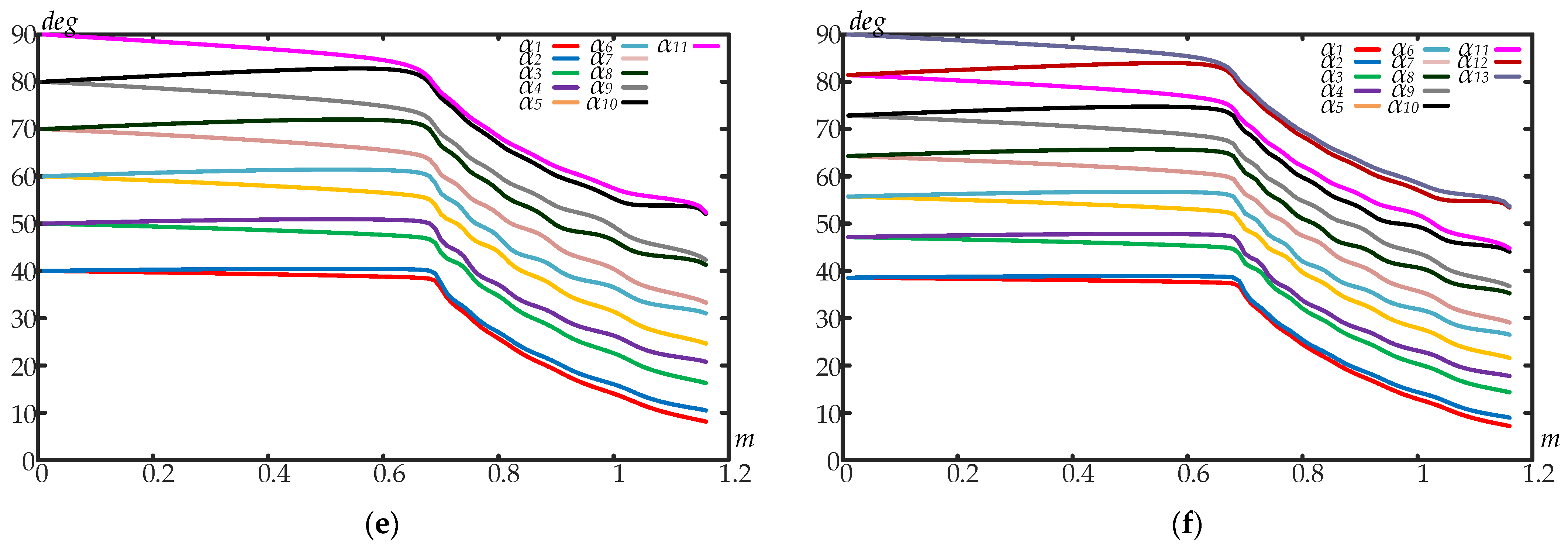
Step 3. Running the calculation algorithm. The developed PSM is implemented in the Matlab R2017b software using an m-file. Figure 2 shows the SHE PPWM switching angles calculated for a quarter-wave symmetry of the unipolar 3L voltage waveform within the modulation factor variation range from 0 to 4/π (solutions were limited to 1.15) at a pitch of 0.01: (a) no. 1–5, 7; (b) no. 2–5, 7, 11, 13; (c) no. 3–5, 7, 11, 13, 17, 19; (d) no. 4–5, 7, 11, 13, 17, 19, 23, 25; (e) no. 5–5, 7, 11, 13, 17, 19, 23, 25, 29, 31; (f) no. 6–5, 7, 11, 13, 17, 19, 23, 25, 29, 31, 35, 37.
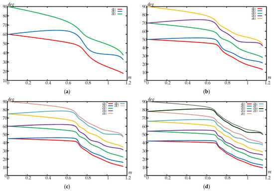
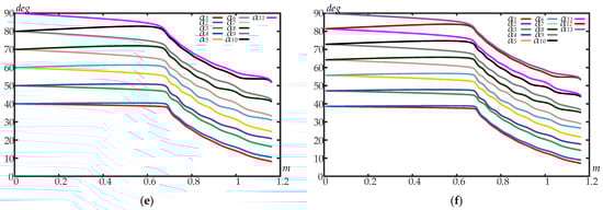
Figure 2.
SHE PPWM switching angles for 3L unipolar voltage waveforms: (a) no. 1–5, 7; (b) no. 2–5, 7, 11, 13; (c) no. 3–5, 7, 11, 13, 17, 19; (d) no. 4–5, 7, 11, 13, 17, 19, 23, 25; (e) no. 5–5, 7, 11, 13, 17, 19, 23, 25, 29, 31; (f) no. 6–5, 7, 11, 13, 17, 19, 23, 25, 29, 31, 35, 37.
4. Studying and Estimating Voltage and Current Spectra
4.1. Defining the Voltage Spectrum
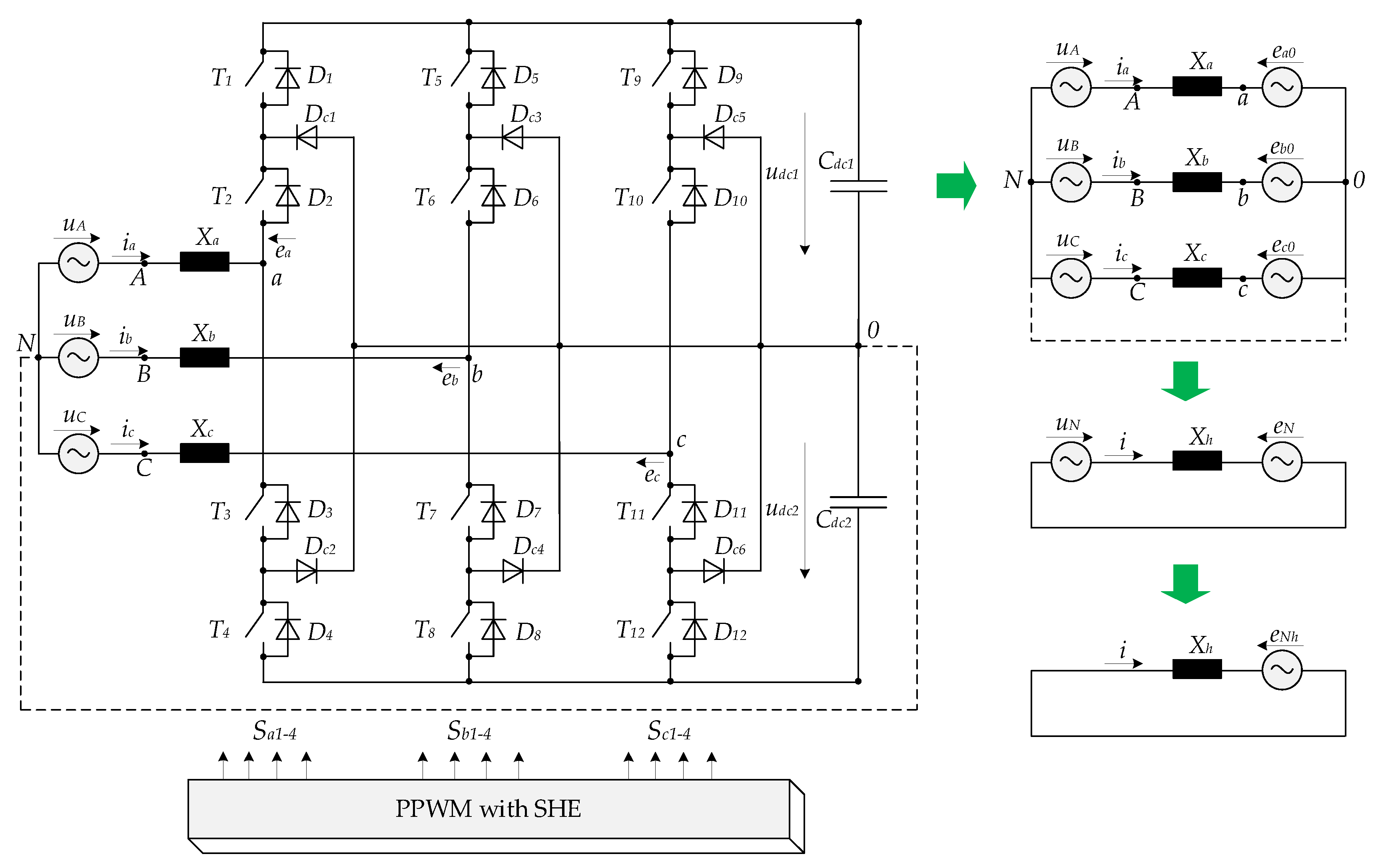
It is advisable to study and estimate the voltage and current spectra based on the example of a 3L-NPC converter. Figure 3 shows its circuit diagram and three-phase and single-phase equivalent circuits. The given NPC topology includes 12 fully controlled semiconductor modules T1–T12, 12 forward diodes D1–D12, and 6 clamped diodes Dc1–Dc6. Figure 3 has the following legend: Sabc1-4 are the states of the semiconductor modules of each phase rack a, b, and c, taking logical values 0 or 1; udc1, udc2 are instantaneous voltage values at the equivalent DC link capacitances; eabc0, iabc are the converter phase EMF and currents; eaN is the converter phase EMF relative to the neutral point of the source N; uABC are the source phase voltages; Cdc1, Cdc2 are equivalent values of DC link capacitances.
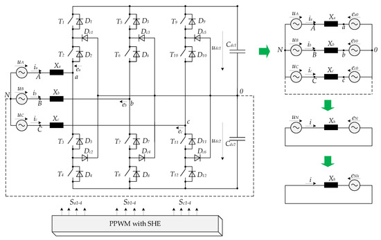
Figure 3.
The 3L-NPC converter circuit.
NPC PWM converter provides imbalance voltages between phases instantaneously. The zero sequence voltage appeared on the neutral point N with respect to ground “0”. The amplitude of this zero sequence voltage is
Using Equation (7), obtain an equation for the NPC converter phase voltage relative to the neutral point of the source N in the form
where the multiple of three harmonics is eliminated.
We substitute switching angles shown in Figure 2 into Equation (15) to obtain harmonic amplitudes in the phase voltage spectrum. Each harmonic amplitude in % from the first harmonic E1m is calculated according to the equation
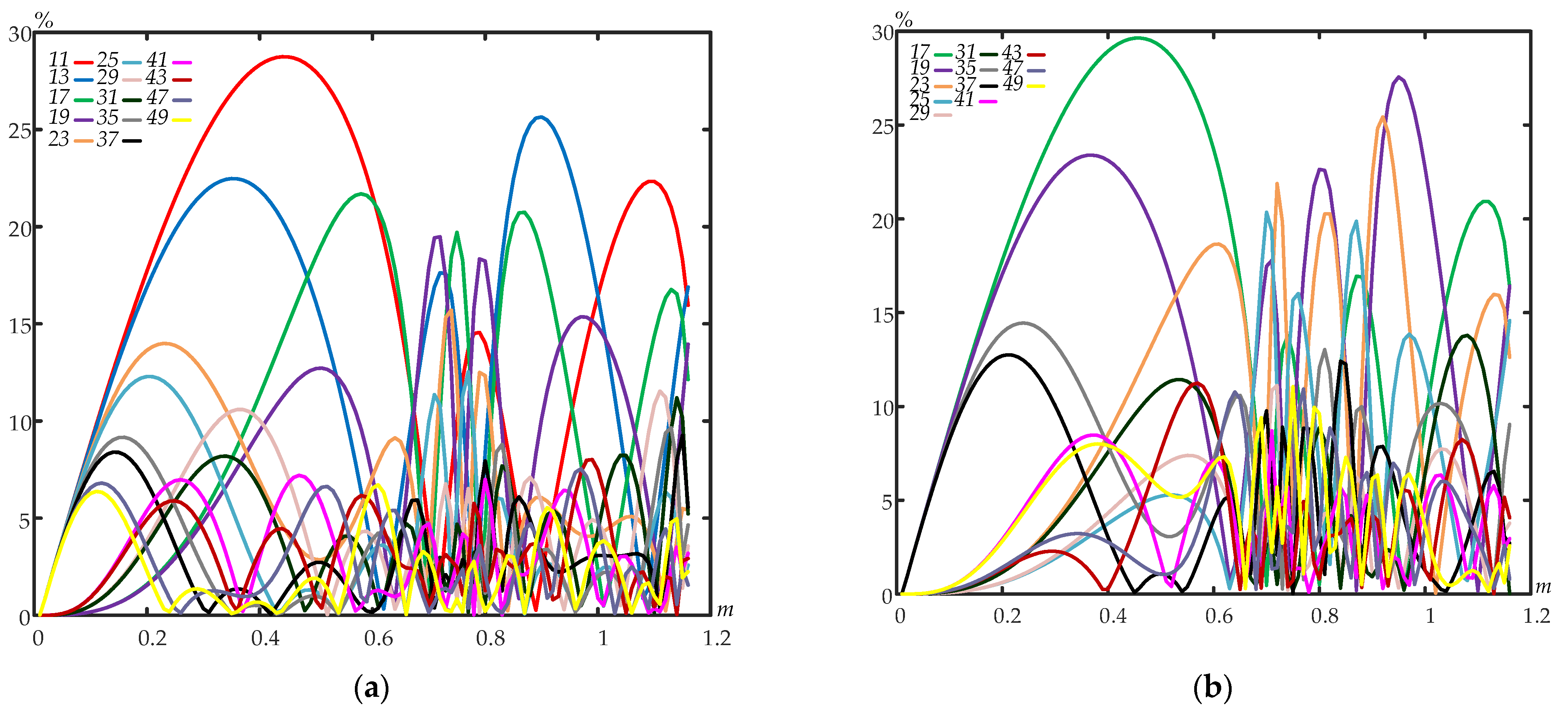
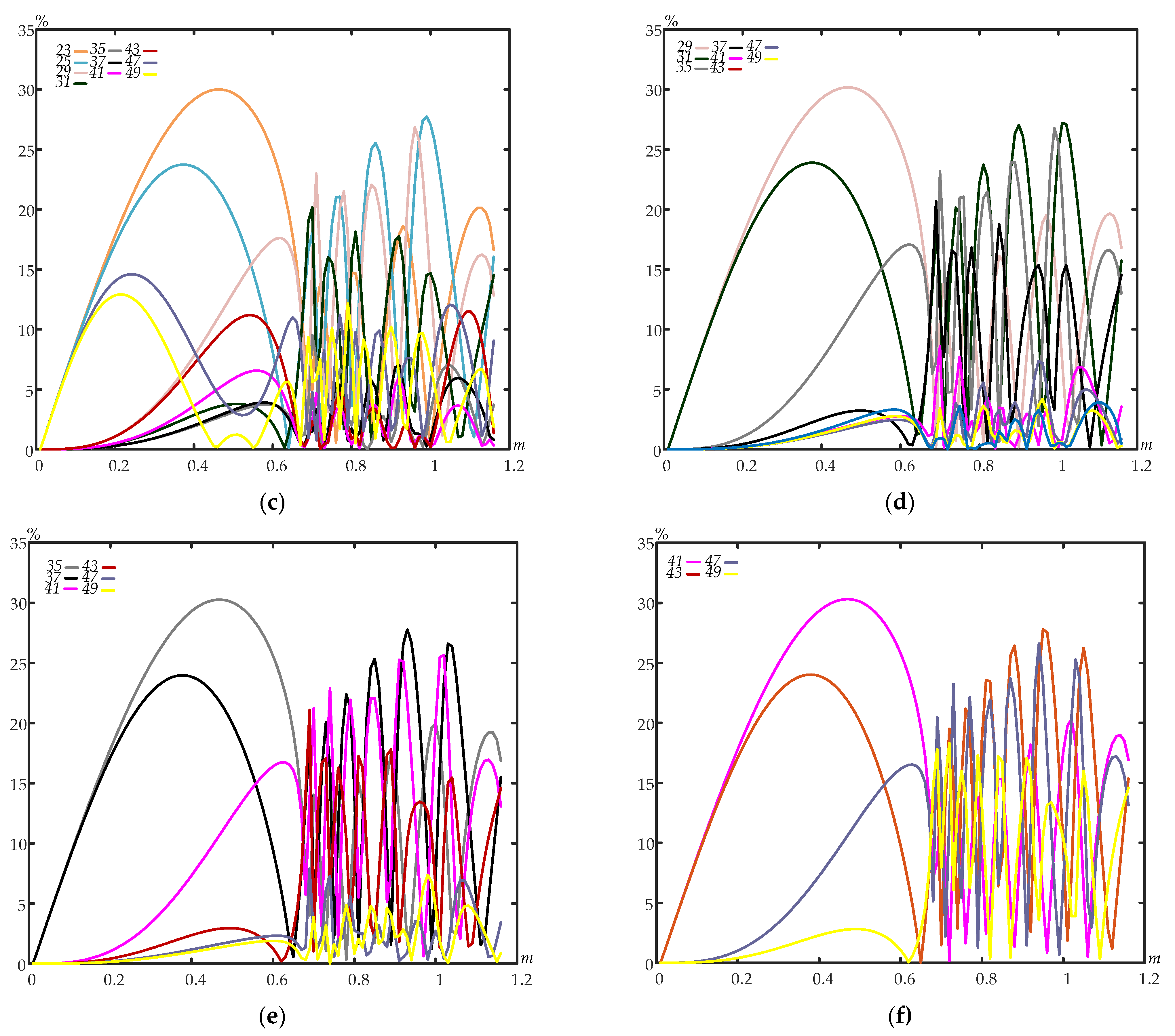
Figure 4 shows the harmonic amplitudes ENhm% calculated over the modulation factor variation range from 0 to 1.15 at a pitch of 0.01 for six different SHE PPWMs considered in Section 3.
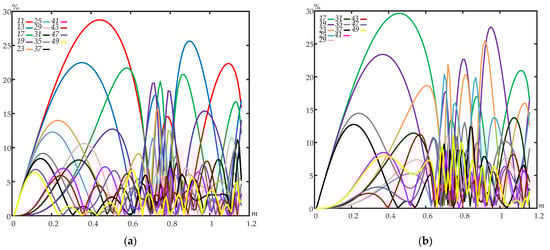

Figure 4.
Spectra of NPC converter 3L voltage waveforms depending on the modulation factor for SHE PPWM: (a) no. 1–5, 7; (b) no. 2–5, 7, 11, 13; (c) no. 3–5, 7, 11, 13, 17, 19; (d) no. 4–5, 7, 11, 13, 17, 19, 23, 25; (e) no. 5–5, 7, 11, 13, 17, 19, 23, 25, 29, 31; (f) no. 6–5, 7, 11, 13, 17, 19, 23, 25, 29, 31, 35, 37.
The analysis of the voltage spectrum harmonic behavior showed the following:
- (1)
- The first harmonic after the last eliminated one has the highest amplitude. E.g., for Programmed Pulse Pattern no. 1 (see Figure 4a), when the 5th and 7th harmonics are eliminated, the 11th harmonic has the highest amplitude; for Programmed Pulse Pattern no. 2 (see Figure 4b), when the 5th, 7th, 11th, and 13th harmonics are eliminated, the 17th harmonic has the highest amplitude, etc.;
- (2)
- The amplitudes of the nearest non-eliminated harmonics coincide with the same modulation factors. E.g., the amplitude of the 23rd harmonic for Programmed Pulse Pattern no. 3 (see Figure 4c) and the 17th harmonic for Programmed Pulse Pattern no. 2 (see Figure 4b), etc., have the same values of 23.54% at a modulation factor of 1.01;
- (3)
- There are several modulation factor values at which various harmonics are eliminated from the spectrum. E.g., the 49th harmonic for Programmed Pulse Pattern no. 5 with a modulation factor of 1.02 (see Figure 4e), the 49th harmonic for Programmed Pulse Pattern no. 6 with a modulation factor of 1.08 (see Figure 4f), etc.;
- (4)
- All amplitudes are variable, but their maximum value does not exceed 30.3%.
To analyze the behavior of the total harmonic distortion of the converter phase voltage depending on the modulation factor, the formula for calculating THD% was applied
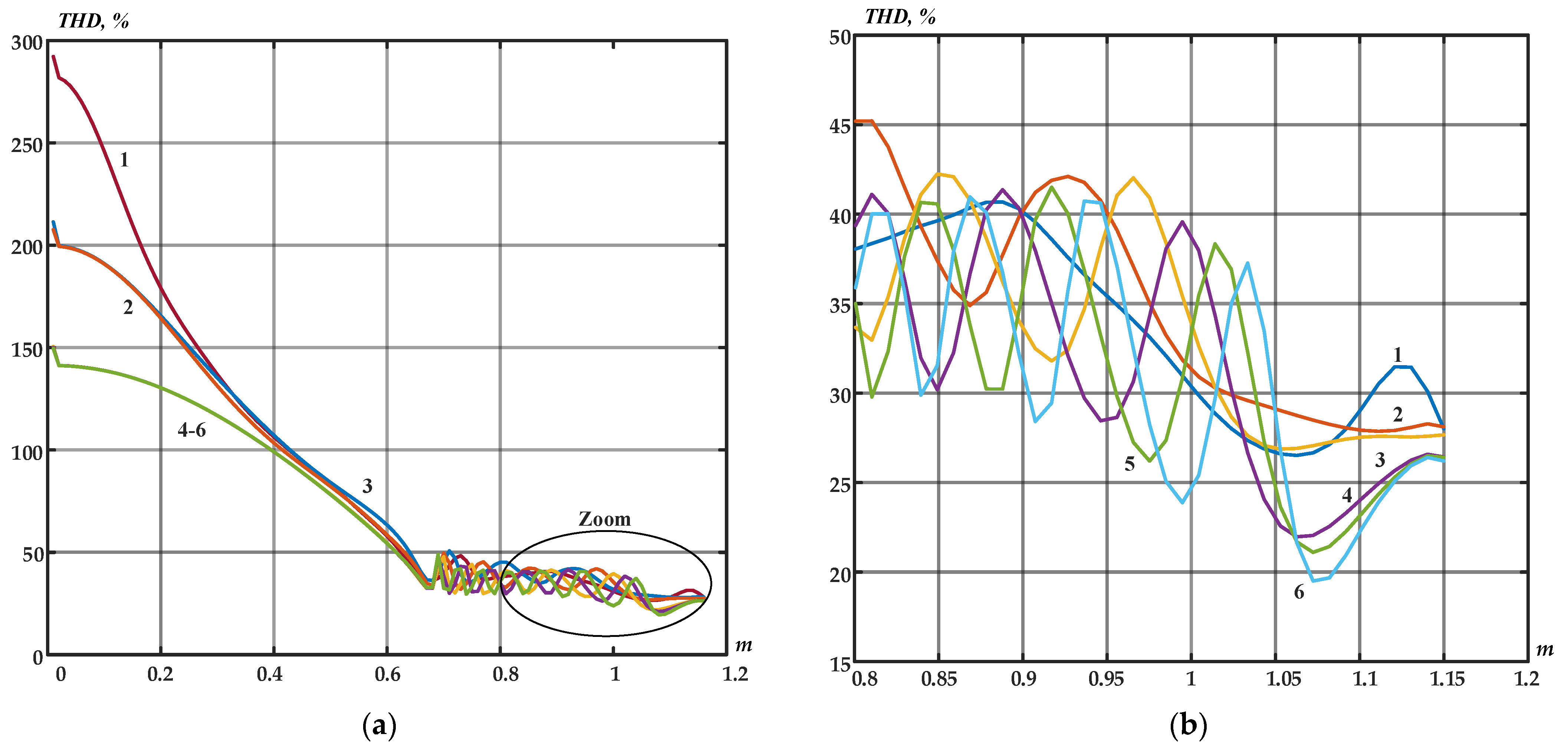
Figure 5 shows the THD% behavior depending on the modulation factor, where all six SHE PPWM sets have a smooth downward trend for m within 0–0.65 (see Figure 5a). There is a clear trend in this interval that SHE PPWMs with multiple switches have less THD%. However, at m within 0.65–1.15 (see Figure 5b), THD% is variable. It is visible that the THD% variation range may reach 20% between different SHE PPWMs for the modulation factor within 0.65–1.15. It is also typical that for all six SHE PPWMs, the minimum THD% is reached for the modulation factor within 1.05–1.1 (see Figure 5b). Thus, increasing the converter’s semiconductor module switching frequency to eliminate more harmonics does not unambiguously improve the converted voltage quality.

Figure 5.
The behavior of the NPC converter phase voltage THD% depending on the modulation factor for six SHE PPWMs: no. 1–5, 7; no. 2–5, 7, 11, 13; no. 3–5, 7, 11, 13, 17, 19; no. 4–5, 7, 11, 13, 17, 19, 23, 25; no. 5–5, 7, 11, 13, 17, 19, 23, 25, 29, 31; no. 6–5, 7, 11, 13, 17, 19, 23, 25, 29, 31, 35, 37; (a) The full modulation factor variation range; (b) Enlarged region at the modulation factor within 0.8–1.15.
4.2. Defining the Current Spectrum
To calculate current harmonics, an equivalent single-phase circuit is used (see Figure 3), including the equivalent inductive reactance Xh of the circuit section
where h is the harmonic order number 1, 5, 7, …; Xh is the circuit section inductive reactance for the h-th harmonic.
The first current harmonic is defined by the formula
If the source voltage UNhm does not contain higher harmonics, and Xh = hωL, the current harmonics can be calculated in % relative to the NPC converter phase voltage harmonic amplitude by the formula
where h is the harmonic order number 5, 7, …;
or in real current amplitudes by the equation
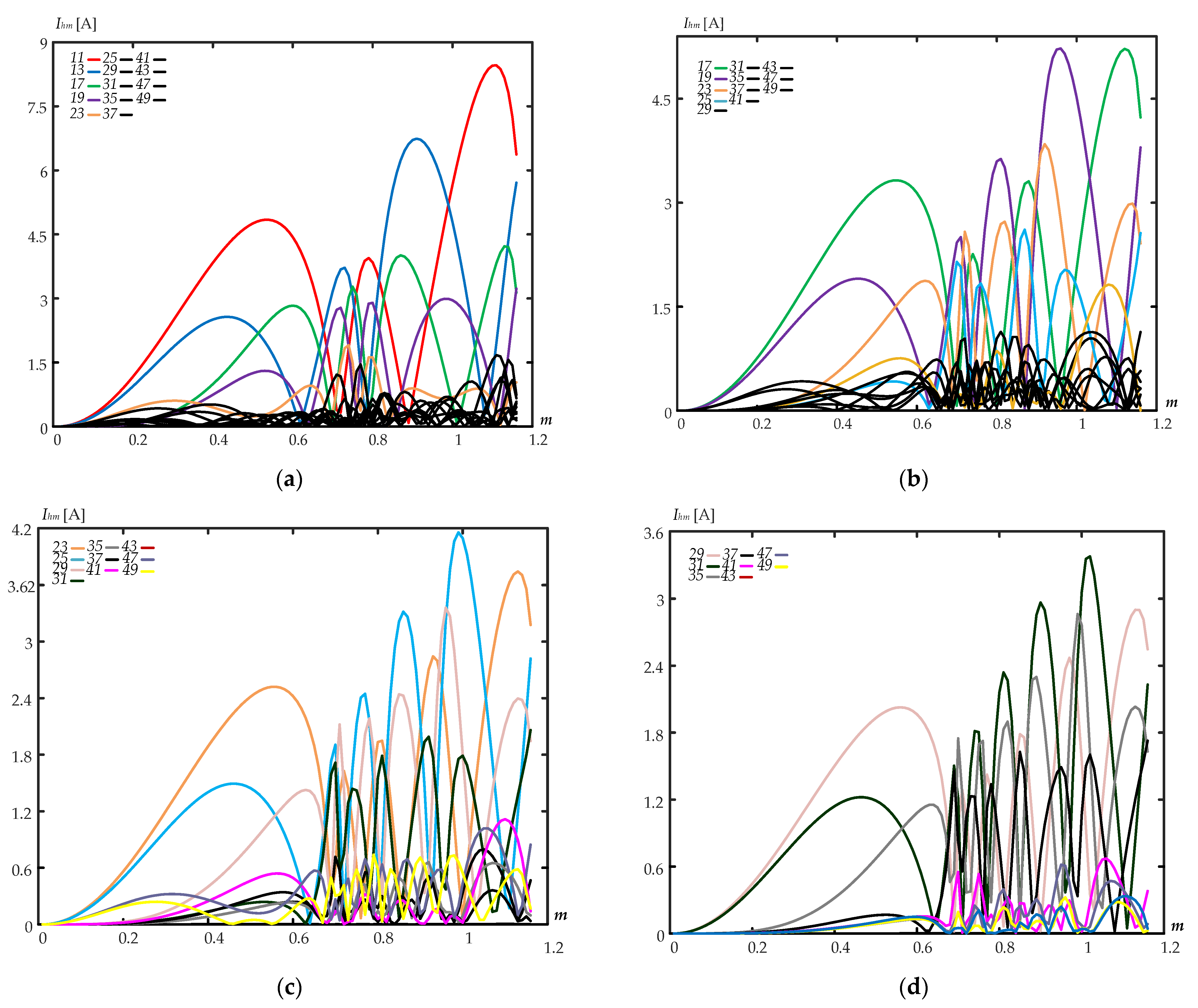
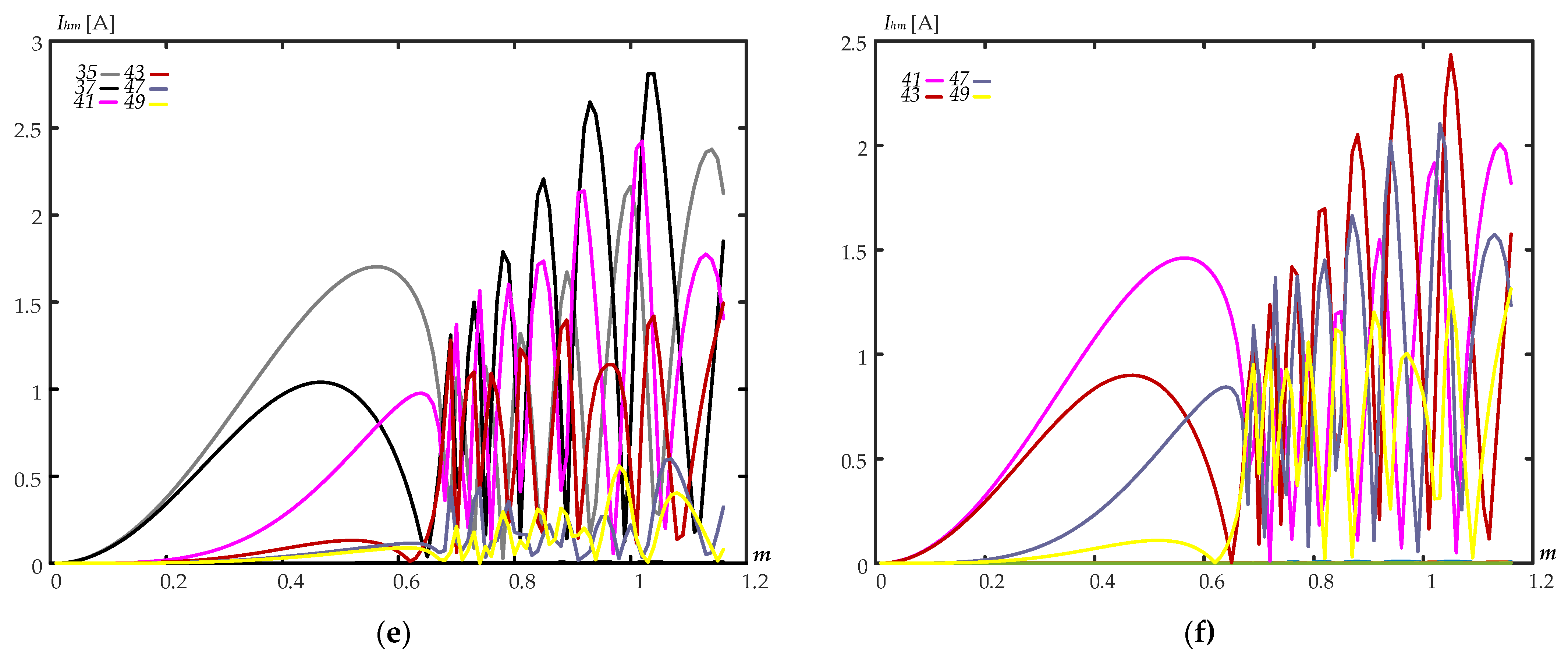
Figure 6 shows the current amplitudes Ihm [A] calculated over the modulation factor variation range within 0–1.15 at a pitch of 0.01 and Udc = 600 V, L = 2.5 mH for six SHE PPWMs considered above in Section 2. The results are given in real amplitudes for the convenience of further comparison with experimental measurements.


Figure 6.
The NPC converter current spectra depending on m for SHE PPWMs: (a) no. 1–5, 7; (b) no. 2–5, 7, 11, 13; (c) no. 3–5, 7, 11, 13, 17, 19; (d) no. 4–5, 7, 11, 13, 17, 19, 23, 25; (e) no. 5–5, 7, 11, 13, 17, 19, 23, 25, 29, 31; (f) no. 6–5, 7, 11, 13, 17, 19, 23, 25, 29, 31, 35, 37.
The analysis of the obtained results has shown that the first four non-eliminated harmonics have the highest amplitudes: 11th, 13th, 17th, and 19th harmonics for Programmed Pulse Pattern no. 1 (see Figure 6a); 17th, 19th, 23rd, and 25th harmonics for Programmed Pulse Pattern no. 2 (see Figure 6b), etc. The provided results show the behavior of higher current harmonics. Typically, most of the higher current harmonic amplitudes shown by black lines in Figure 6a,b are greatly reduced over the entire m variation range.
5. Experimental Results
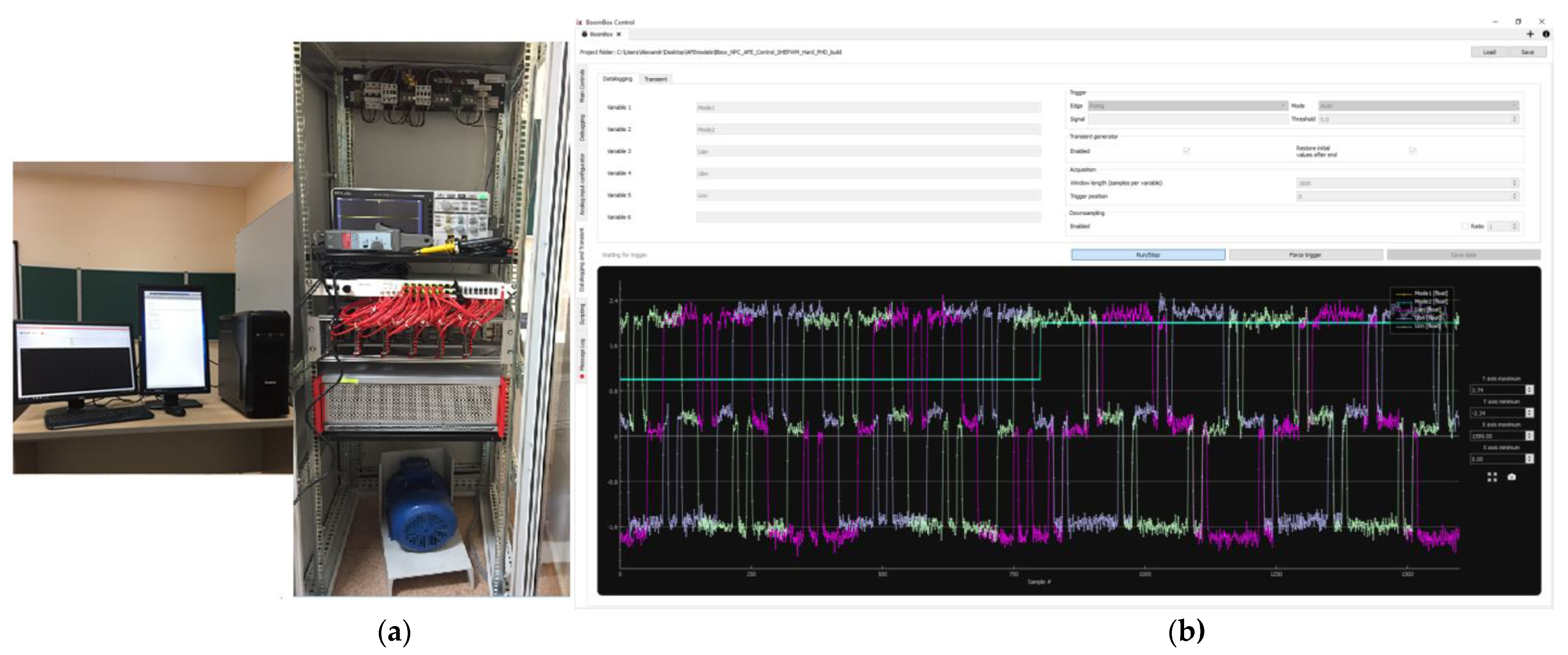
A generalized composition of software and hardware of the stand is given in Figure 7a. The laboratory equipment parameters are provided in Table 2. The gates of the IGBTs have been connected by optical fiber. The 3L-NPC converter are controlled by the digital signal processor (DSP) and the field-programmable gate array (FPGA). The FPGA includes analog–digital converters (ADC) and PWM while the DSP provides a closed-loop control system of the 3L-NPC converter. The patterns of switching angles were uploaded to DSP memory offline. The control system generates the reference modulation factor and phase angle, and then, switching angles are initialized from the DSP memory. In transitional processes of instantaneous voltage and current at the input of the 3L-NPC converter, the WindowsTM software was used [32]; the example is shown in Figure 7b.

Figure 7.
Labor equipment: (a) general view photo and (b) WindowsTM-based graphic software of the BoomBox.
Table 2.
Labor equipment data.
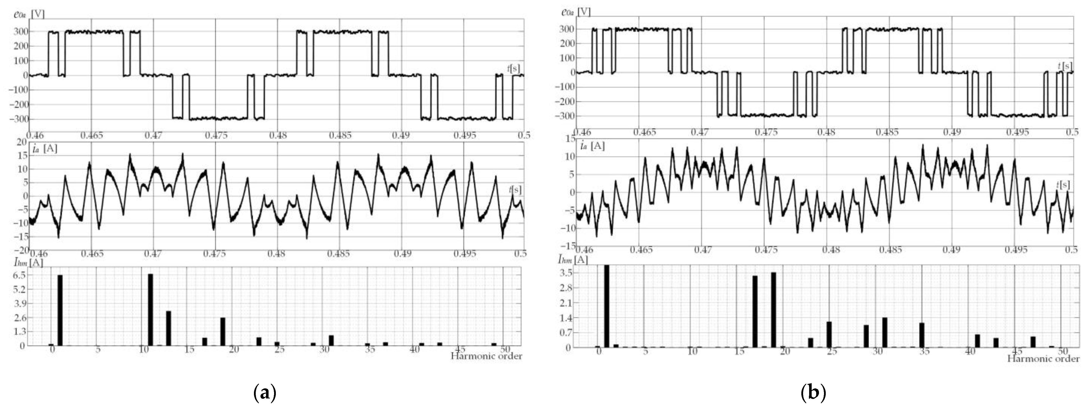
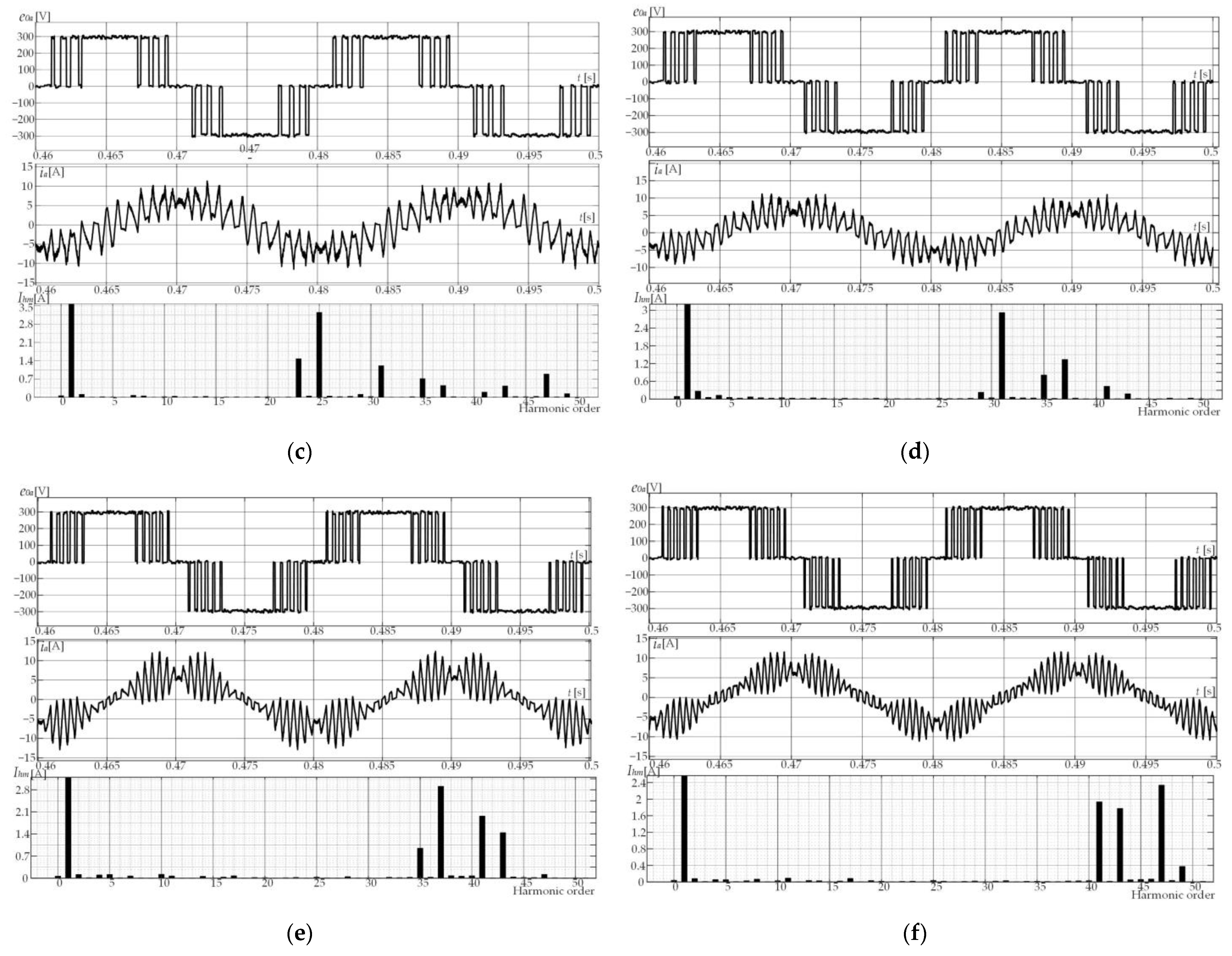
The SHE PPWMs calculated in Section 2 were loaded into the microcontroller memory in tabular form in the Matlab/Simulink R2017b software environment using the JTAG emulator. The currents measured in the NPC converter power circuit were recorded using a console USB connection to the BoomBox control platform and the BoomBox control software. Figure 8 shows oscillograms for a modulation factor of 1.02, Udc = 600 V, L = 2.5 mH, and six SHE PPWMs with measured NPC converter phase voltages relative to the DC link zero point, instantaneous values of consumed current ia(ωt), and current harmonic amplitudes Ihm.
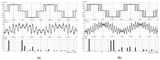

Figure 8.
The NPC converter phase voltage and current oscillograms at m = 1.02 for six SHE PPWMs: (a) no. 1–5, 7; (b) no. 2–5, 7, 11, 13; (c) no. 3–5, 7, 11, 13, 17, 19; (d) no. 4–5, 7, 11, 13, 17, 19, 23, 25; (e) no. 5–5, 7, 11, 13, 17, 19, 23, 25, 29, 31; (f) no. 6–5, 7, 11, 13, 17, 19, 23, 25, 29, 31, 35, 37.
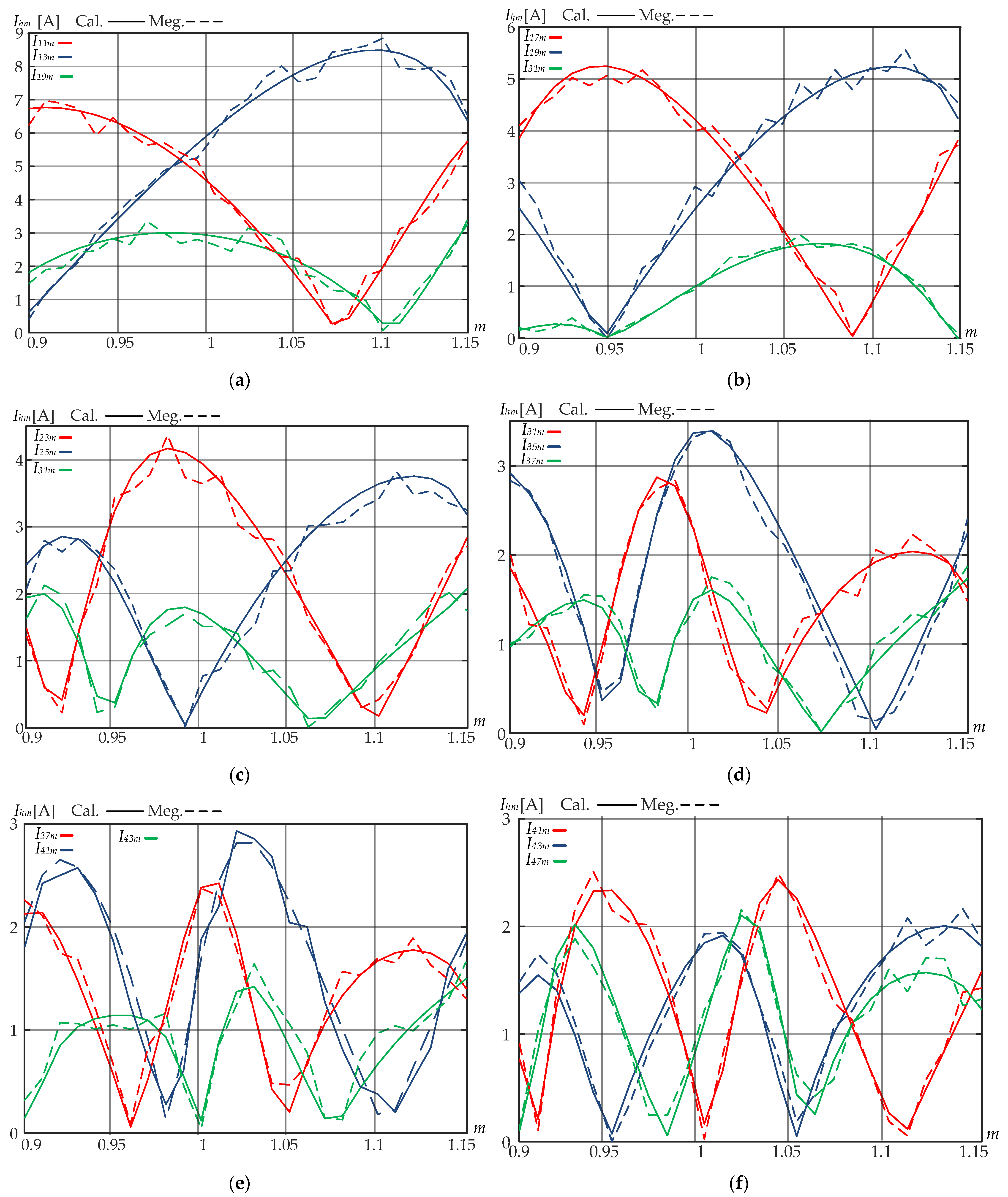
Figure 9 provides the results of comparing the calculated current amplitudes with the measured ones. The results are given for the three most significant harmonics at a modulation factor range from 0.9 to 1.15.

Figure 9.
A comparative result of the calculated and the measured harmonics at the modulation factor range from 0.9 to 1.15 for six SHE PPWMs: (a) no. 1–5, 7; (b) no. 2–5, 7, 11, 13; (c) no. 3–5, 7, 11, 13, 17, 19; (d) no. 4–5, 7, 11, 13, 17, 19, 23, 25; (e) no. 5–5, 7, 11, 13, 17, 19, 23, 25, 29, 31; (f) no. 6–5, 7, 11, 13, 17, 19, 23, 25, 29, 31, 35, 37.
The comparative analysis results calculated by Equation (21) and the measured amplitudes of the current consumed by the NPC converter showed good convergence. According to Figure 9, the average error does not exceed 6%. Thus, this proves the possibility to use Equations (15) and (21) to define the NPC converter voltage and current spectra. Note that the measurements were performed while providing the voltage balance at the DC link equivalent capacities and the absence of higher harmonics in the supply voltage.
6. Conclusions
The paper’s contribution can be described as follows:
- (1)
- The behavior of up to the 50th amplitude of the NPC converter voltage and consumed current harmonics was studied within the modulation factor variation range from 0 to 1.15 at a pitch of 0.01 for six SHE PPWMs. The results obtained can be used to choose passive filters and define the most dangerous resonance impact zones for both an electric circuit within the modulation factor variation range from 0.9 to 1.15 and motors within the modulation factor variation range from 0 to 1.15;
- (2)
- Herein, for the first time, the pre-calculated NPC converter current spectra have been experimentally verified for a six-pulse connection circuit for six SHE PPWMs. The simulation and experimental results differ with the engineering degree of accuracy;
- (3)
- The research opens new opportunities for further study into and estimation of the NPC converters impact for more complex multi-pulse power connection circuits, resonant phenomena, and optimal SHE PPWMs calculated using advanced search algorithms;
- (4)
- The study is promising for high-power power converters with a limited semiconductor module switching frequency. The study results are applicable to solve the problems of ensuring electromagnetic compatibility, improving energy efficiency, and optimizing the semiconductor converter power losses;
- (5)
- The research opens new possibilities for calculating or reducing current harmonics of 3L-NPC converters with PPWM to be published in further papers.
Author Contributions
Conceptualization, A.S.M.; methodology, A.S.M.; software, A.S.M.; validation, A.S.M.; formal analysis, A.S.M.; investigation, A.S.M.; resources, I.N.E.; data curation, A.S.M.; writing—original draft preparation, A.S.M.; writing—review and editing, A.S.M. and I.N.E.; visualization, I.N.E.; supervision, A.S.M.; project administration, A.S.M. All authors have read and agreed to the published version of the manuscript.
Funding
This work was financially supported by the Moscow Polytechnic University within the framework of the grant named after Pyotr Kapitsa.
Institutional Review Board Statement
Not applicable.
Informed Consent Statement
Not applicable.
Data Availability Statement
Not applicable.
Conflicts of Interest
The authors declare no conflict of interest.
References
- Cheng, J.; Xu, T.; Chen, D.; Chen, G. Dynamic and steady state response analysis of selective harmonic elimination in high power inverters. IEEE Access 2021, 9, 75588–75598. [Google Scholar] [CrossRef]
- Gabour, N.E.H.; Habbi, F.; Bounekhla, M.; Boudissa, E.G. Enhanced Harmonic Elimination Using Genetic Algorithm Optimization in Multilevel Inverters. In Proceedings of the 18th International Multi-Conference on Systems, Signals & Devices, Monastir, Tunisia, 22–25 March 2021. [Google Scholar]
- Hoevenaars, A.; Farbis, M.; McGraw, M. Active harmonic mitigation: What the manufacturers don’t tell you. IEEE Ind. Appl. Mag. 2020, 62, 41–51. [Google Scholar] [CrossRef]
- Janabi, A.; Wang, B.; Czarkowski, D. Generalized Chudnovsky algorithm for real-time PWM selective harmonic elimination/modulation: Two-Level VSI example. IEEE Trans. Power Electron. 2020, 35, 5437–5446. [Google Scholar] [CrossRef]
- Jiang, Y.; Li, X.; Qin, C.; Xing, X.; Chen, Z. Improved particle swarm optimization based selective harmonic elimination and neutral point balance control for three-level inverter in low-voltage ride-through operation. IEEE Trans. Ind. Inform. 2022, 18, 642–652. [Google Scholar] [CrossRef]
- Memon, M.A.; Siddique, M.D.; Saad, M.; Mubin, M. Asynchronous particle swarm optimization-genetic algorithm (APSO-GA) based selective harmonic elimination in a cascaded H-bridge multilevel inverter. IEEE Trans. Ind. Electron. 2022, 69, 1477–1487. [Google Scholar] [CrossRef]
- Sadoughi, M.; Zakerian, A.; Pourdadashnia, A.; Farhadi-Kangarlu, M. Selective Harmonic Elimination PWM for Cascaded H-bridge Multilevel Inverter with Wide Output Voltage Range Using PSO Algorithm. In Proceedings of the IEEE Texas Power and Energy Conference, College Station, TX, USA, 1–6 February 2021. [Google Scholar]
- Maklakov, A.S.; Jing, T.; Radionov, A.A.; Gasiyarov, V.R.; Lisovskaya, T.A. Finding the best programmable PWM pattern for three-level active front-ends at 18-pulse connection. Machines 2021, 9, 127. [Google Scholar] [CrossRef]
- Maklakov, A.S.; Jing, T.; Nikolaev, A.A.; Gasiyarov, V.R. Grid Connection Circuits for Powerful Regenerative Electric Drives of Rolling Mills: Review. Energies 2022, 15, 8608. [Google Scholar] [CrossRef]
- Jing, T.; Maklakov, A.; Radionov, A.; Gasiyarov, V.; Liang, Y. Formulations, Solving Algorithms, Existing Problems and Future Challenges of Pre-Programmed PWM Techniques for High-Power AFE Converters: A Comprehensive Review. Energies 2022, 15, 1696. [Google Scholar] [CrossRef]
- Pontt, J.; Rodriguez, J.; Huerta, R. Mitigation of noneliminated harmonics of SHEPWM three-level multipulse three-phase active front end converters with low switching frequency for meeting standard IEEE-519-92. IEEE Trans. Power Electron. 2004, 19, 1594–1600. [Google Scholar] [CrossRef]
- Annoukoubi, M.; Essadki, A.; Laghridat, H.; Nasser, T. Comparative study between the performances of a three-level and two-level converter for a Wind Energy Conversion System. In Proceedings of the 2019 International Conference on Wireless Technologies, Embedded and Intelligent Systems (WITS), Fez, Morocco, 3–4 April 2019; pp. 1–6. [Google Scholar] [CrossRef]
- Yang, K.; and Feng, M.; Wang, Y.; Lan, X.; Wang, J.; Zhu, D.; Yu, W. Real-Time Switching Angle Computation for Selective Harmonic Control. IEEE Trans. Power Electron. 2019, 34, 8201–8212. [Google Scholar] [CrossRef]
- Ni, Z.; Abuelnaga, A.H.; Badawi, S.; ad Yuan, S.; Pan, Y.; Narimani, M.; Cheng, Z.; Zargari, N.R. Control of Regenerative CHB Motor Drives at Fundamental Switching Frequency. IEEE Trans. Power Electron. 2023, 38, 3352–3362. [Google Scholar] [CrossRef]
- Vassilios, G.A.; Anastasios, I.B.; Calum, C. On Attaining the Multiple Solutions of Selective Harmonic Elimination PWM Three-Level Waveforms Through Function Minimization. IEEE Trans. Ind. Electron. 2008, 55, 996–1004. [Google Scholar]
- Cong, W.; Zhao, F.; Guo, X.; Wen, X.; Wang, Y.; Song, X. Analysis and experimental verification for multiple solutions of bipolar SHEPWM waveforms applied in control system of induction machines. In Proceedings of the 2011 International Conference on Electrical Machines and Systems, Beijing, China, 20–23 August 2011; pp. 1–4. [Google Scholar] [CrossRef]
- Shenjian, Z.; Cheng, Y.; Yangfan, Z.; Wenjie, C.; Dehong, X. Suppressing the side effect of the grid background harmonics on grid inverter with selective harmonic elimination PWM. In Proceedings of the 2014 International Power Electronics and Application Conference and Exposition, 5–8 November 2014; pp. 508–513. [Google Scholar]
- Ali, Z.; Christofides, N.; Tahir, M.; Saleem, K.; Gul, M.; ul Hasnain, S.R.; Khan, B. Generalized method for harmonic elimination in two and three level voltage sourced converters. In Proceedings of the 2015 International Conference on Emerging Technologies (ICET), Peshawar, Pakistan, 19–20 December 2015; pp. 1–6. [Google Scholar] [CrossRef]
- Bhadra, S.; Patangia, H. A Unified Analytical Solution for Bipolar, Unipolar, and Multistep SHE Converters. In Proceedings of the 2018 IEEE International Symposium on Circuits and Systems (ISCAS), Florence, Italy, 27–30 May 2018; pp. 1–5. [Google Scholar] [CrossRef]
- Prabhu, O.; Jagdish, K.; Balwinder, S.S. Optimized SHE-PWM Technique for Low Distortion Single Phase MLI for PV Standalone System. In Proceedings of the 2018 5th IEEE Uttar Pradesh Section International Conference on Electrical, Electronics and Computer Engineering (UPCON), Gorakhpur, India, 2–4 November 2018; pp. 1–6. [Google Scholar]
- Poon, J.; Sinha, M.; Dhople, S.V.; Rivas-Davila, J. Real-time Selective Harmonic Minimization Using a Hybrid Analog/Digital Computing Method. IEEE Trans. Power Electron. 2022, 37, 5078–5088. [Google Scholar] [CrossRef]
- Arash, M.; Firuz, Z.; Dinesh, K.; Jalil, Y.; Rahul, S.; Dirk, K. Current Harmonics Generated by Multiple Adjustable-Speed Drives in Distribution Networks in the Frequency Range of 2–9 kHz. IEEE Trans. Ind. Appl. 2022, 58, 4744–4757. [Google Scholar]
- Mohammad, S.; Hani, V.; Ramon, P.; Mohammad, K.; Abdolreza, S.; Leopoldo, G.F.; Kamal, A. Hybrid SHM-SHE Pulse-Amplitude Modulation for High-Power Four-Leg Inverter. IEEE Trans. Ind. Electron. 2016, 63, 7234–7242. [Google Scholar]
- Omara, A.M.; Sleptsov, M.; El-Nemr, M.K. Genetic algorithm optimization of SHE-PWM technique for paralleled two-module VSIs employed in electric drive systems. In Proceedings of the 2018 25th International Workshop on Electric Drives: Optimization in Control of Electric Drives (IWED), Moscow, Russia, 31 January–2 February 2018; pp. 1–6. [Google Scholar] [CrossRef]
- Moradi, A.; Yaghoobi, J.; Zare, F.; Kumar, D.; Sharma, R.; Kroese, D. Current Harmonics Generated by Multi-power Converters in Distribution Networks in the Frequency Range of 2–9 kHz. In Proceedings of the 2021 IEEE 19th International Power Electronics and Motion Control Conference (PEMC), Gliwice, Poland, 25–29 April 2021; pp. 534–540. [Google Scholar] [CrossRef]
- Rai, N.; Chakravorty, S. Hybrid-GA based multiple solutions for Selective Harmonic Elimination in Bipolar PWM waveforms. In Proceedings of the 2020 IEEE 5th International Conference on Computing Communication and Automation (ICCCA), Greater Noida, India, 30–31 October 2020; pp. 703–707. [Google Scholar] [CrossRef]
- Balasubramonian, M.; Rajamani, V. Design and Real-Time Implementation of SHEPWM in Single-Phase Inverter Using Generalized Hopfield Neural Network. IEEE Trans. Ind. Electron. 2014, 61, 6327–6336. [Google Scholar] [CrossRef]
- Wang, Q.; Zhang, Y.; Li, C.; Li, W.; He, X. Comprehensive Comparison between Two-Level, Three-Level, and Hybrid Three-Level SiC Inverter for High Power High-Speed Drive System. In Proceedings of the 2020 IEEE 9th International Power Electronics and Motion Control Conference (IPEMC2020-ECCE Asia), Nanjing, China, 29 November–2 December 2020; pp. 1884–1889. [Google Scholar] [CrossRef]
- Nikolaev, A.A.; Gilemov, I.G.; Bulanov, M.V.; Kosmatov, V.I. Providing Electromagnetic Compatibility of High-Power Frequency Converters with Active Rectifiers at Internal Power Supply System of Cherepovets Steel Mill. In Proceedings of the International Scientific-Technical Conference Alternating Current Electric Drives, Ekaterinburg, Russia, 1–8 May 2021. [Google Scholar]
- Nikolaev, A.; Maklakov, A.; Bulanov, M.; Gilemov, I.; Denisevich, A.; Afanasev, M. Current Electromagnetic Compatibility Problems of High-Power Industrial Electric Drives with Active Front-End Rectifiers Connected to a 6–35 kV Power Grid: A Comprehensive Overview. Energies 2023, 16, 293. [Google Scholar] [CrossRef]
- Holmes, D.G.; Lipo, T.A. Programmed Modulation Strategies. In Pulse Width Modulation for Power Converters: Principles and Practice; IEEE: Piscataway, NJ, USA, 2003; pp. 383–431. [Google Scholar] [CrossRef]
- Maklakov, A.S.; Jing, T.; Nikolaev, A.A. Comparative Analysis of Current and Voltage THD at Different Grid Powers for Powerful Active Front-End Rectifiers with Preprogrammed PWM. Machines 2022, 10, 1139. [Google Scholar] [CrossRef]
Disclaimer/Publisher’s Note: The statements, opinions and data contained in all publications are solely those of the individual author(s) and contributor(s) and not of MDPI and/or the editor(s). MDPI and/or the editor(s) disclaim responsibility for any injury to people or property resulting from any ideas, methods, instructions or products referred to in the content. |
© 2023 by the authors. Licensee MDPI, Basel, Switzerland. This article is an open access article distributed under the terms and conditions of the Creative Commons Attribution (CC BY) license (https://creativecommons.org/licenses/by/4.0/).