Article

Computational Analysis on Combustion Control of Diesel Engines Fueled with Ester Alcohol Diesel

1
School of Aeronautical Electromechanical Equipment Maintenance, Airforce Aviation Repair Institute of Technology, Changsha 410073, China
2
School of Aeronautics and Astronautics, Central South University, Changsha 410073, China
3
School of Automotive and Traffic Engineering, Jiangsu University, Zhenjiang 212013, China
*
Author to whom correspondence should be addressed.
Energies 2023, 16(16), 6093; https://doi.org/10.3390/en16166093
Submission received: 30 June 2023 / Revised: 30 July 2023 / Accepted: 17 August 2023 / Published: 21 August 2023
(This article belongs to the Special Issue Biomass and Biofuel for Renewable Energy)

Abstract

:
As the urgency for environmental sustainability escalates globally, the exploration of alternative fuels for diesel engines becomes a crucial endeavor. By combining chemical reaction kinetics and three-dimensional simulation software, the combustion and emission characteristics of a diesel engine fueled with two oxygenated fuels, hydrogenated biodiesel and ethanol, and adopting a multi-stage injection strategy were studied. The combustion mechanism of hydrogenated biodiesel ethanol diesel hybrid fuel was established, and the reaction activity of ester alcohol diesel with different mixing ratios was studied through reaction flow analysis at high and low OH temperatures. The established mechanism was coupled with CFD 2021 three-dimensional simulation software to compare the combustion and emission performance of diesel engines fueled with different ratios of ester alcohol diesel. The results show that as the proportion of ester alcohol mixture increases, at low temperatures, the OH generation rate decreases, the consumption rate increases, and the reaction activity decreases, which is not conducive to the promotion of combustion reaction; at high temperatures, the generation rate of OH increases, the consumption rate decreases, and the reaction activity increases, which is conducive to the promotion of combustion reactions. Compared to diesel, the reaction system activity of mixed fuel is enhanced, and the main peak values of cylinder pressure and instantaneous heat release rate are higher than that of diesel. The diffusion of oil and gas in the cylinder is improved. As the proportion of ester alcohol diesel mixture increases, the oxygen content increases, nitrogen oxides emissions increase compared to diesel, and soot emissions decrease compared to diesel. Soot emissions are mainly distributed in areas with a high equivalence ratio and high temperature, which is consistent with the distribution area of C2H2, the precursor of soot generation.

1. Introduction

The increasing global concerns regarding environmental degradation and the impending depletion of conventional fossil fuels have necessitated a focused [1] and collective global effort to explore sustainable [2] and environmentally [3] benign energy alternatives. Diesel engines [4], renowned for their superior efficiency and torque [5], have found extensive applications in transportation and industrial sectors [6]. However, they are associated with substantial greenhouse gas emissions and air pollution [7]. This worrying scenario has instigated an intense search for alternate fuels [8] that can replace traditional diesel with a reduced environmental footprint [9].
Ester alcohol fuels, typically derived from renewable resources [10], have emerged as a promising candidate in this context [11]. They are distinguished by unique physicochemical properties, such as higher oxygen content and lower potential for soot formation [12]. These properties mark them as promising contenders for cleaner and more efficient combustion [13]. Comprehending the combustion process of ester alcohol fuels in diesel engines is crucial to their effective deployment, and this topic is currently a focal point of intensive research [14].
In recent decades, advancements in the realms of thermodynamics, chemical reaction kinetics [15], and computational fluid dynamics (CFD) have been significant [16]. These strides have given rise to sophisticated simulation technologies that incorporate both CFD and chemical kinetics [17], now deemed indispensable for investigating intricate combustion processes within diesel engines [18]. These high-resolution, detailed simulations empower researchers to optimize engine performance [19] and curb emissions significantly [20].
Bio-diesel is one such alternative fuel [21] that has garnered considerable interest due to its physical [22] and chemical properties [23], closely mirroring conventional diesel [9]. It can be employed in modern direct-injection diesel engines [24] with minimal alterations [25], thereby positioning it as a practical [26], immediate solution [27]. Numerous studies validate that bio-diesel can curtail emissions of CO2 [28], hydrocarbons [29], and soot by up to 50% [30], highlighting its potential in reducing [31] the environmental impact of diesel engines [32]. However, the increase of approximately 10% in NOx emissions [33] when using bio-diesel remains an issue that warrants resolution [34].
One popular strategy to manipulate combustion characteristics [35] and emissions is the blending of oxygenated fuels [36] with diesel. The research landscape in this domain is extensive and complex [37], with multiple studies delving into various aspects of this approach. For example, Sun [38] conducted a meticulous exploration into the influence of pre-injection and post-injection on the NOx emissions of bio-diesel engines by leveraging the synergy of experimentation and simulation. Her research elucidated that NOx emissions diminish with the amplification of pre-main spray intervals, while post-injection augments NOx emissions. He [39] examined the impact of a 20% volumetric blend of bio-diesel on NOx emissions from diesel engines under high-speed, full-load conditions, deploying both single-stage and multi-stage injection strategies. His findings unveiled that multi-stage injection tactics could effectively mitigate NOx emissions, but the engine’s NOx emission levels after the introduction of a 20% volumetric bio-diesel blend remained elevated compared to pure diesel. Wang [40] and others conducted intricate computational simulations of the in-cylinder soot formation under diesel engine combustion conditions. The results accentuated the significant influence of combustion temperature and mixture equivalence ratio on soot generation. Li [41] and others simulated the effect of two-stage injection on soot emissions. The results evinced that pre-injection can effectively curtail the production of soot precursors, thereby reducing soot emissions.
Despite this progress, research on the concurrent blending of two different oxygenated fuels, like bio-diesel and ethanol, for diesel engine combustion, is relatively scarce. Considering the unique properties of these fuels, their combined use could potentially result in distinctive combustion characteristics and emission profiles. Consequently, gaining a deep understanding of their fundamental mechanisms when used in combination is vital to performance optimization and emission control.
In our study, we intend to bridge this research gap by investigating the impacts of different blending ratios of ester alcohol diesel fuel on the combustion mixture and emissions’ formation. We are utilizing state-of-the-art simulation methods, combining chemical reaction kinetics and three-dimensional CFD, to probe the combustion process from both macroscopic and microscopic perspectives. We hope that our research will pave the way for a deeper understanding of ester alcohol fuels and contribute to the development of more efficient and environmentally friendly diesel combustion strategies.

2. Computational Model Construction and Validation

2.1. Construction of Simplified Chemical Kinetic Model

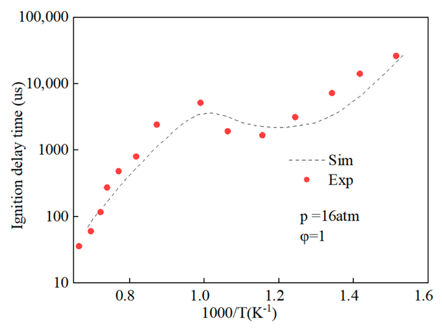
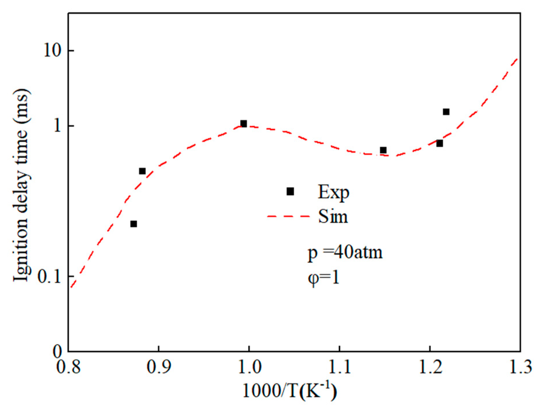
Prior to amalgamating the mechanistic models of hydrobiodiesel, ethanol, diesel, and other fuel oxidation reactions, we commenced with the distillation and analysis of crucial primitive and main reactions, in addition to key components, in the models of methyl oleate, methyl stearate, ethanol, and n-heptane. Following this, mechanism models were derived through multipolar simplification, utilizing ignition delay and molar concentration of pivotal components’ experimental data as the reference for validating these simplified models. The fire delay period was used as the target parameter, and the error threshold was set at 10% for detailed mechanistic simplification. According to the hierarchical construction method, based on the simplified kinetic mechanism model of the chemical reaction of the characterized components, the simplified mechanism model of hydrogenated biodiesel is constructed. The simplified mechanism model of hydrogenated biodiesel: Methyl stearate and methyl oleate are the two components with the highest proportion in hydrogenated bio-diesel. Based on the composition and important physicochemical properties such as cetane number of hydrogenated bio-diesel, a mixture of 78.7% methyl oleate and 21.3% methyl stearate is used as the surrogate for hydrogenated bio-diesel; this is based on the detailed mechanisms of methyl oleate and methyl stearate constructed by Westbrook et al. [31] under conditions of temperature 800–1500 K, equivalence ratio 0.5–2.0, pressure 0.1–6 MPa, which include 402 components and 16,188 reactions, and 423 components and 17,436 reactions, respectively. By using Directed Relation Graph (DRG), DRG with Error Propagation (DRGEP), and the Sensitivity Analysis Method, a simplified mechanism of methyl oleate and methyl stearate was finally obtained, including 71 components with 273 reactions, and 67 components with 246 reactions. Figure 1 and Figure 2 show the ignition delay periods predicted by the simplified mechanisms of methyl oleate [32] and methyl stearate [34] with experimental values.
The simplified mechanism of hydrogenated bio-diesel was obtained by adding the elementary reactions and components that are unique to methyl oleate, which are different from those in methyl stearate, into the simplified mechanism of methyl stearate, which contains 104 components and 427 reactions. Figure 3 shows the comparison of the ignition delay period predicted by the simplified mechanism of hydrogenated bio-diesel and the experimental values of ignition delay period of methyl oleate measured by Hammill et al. [42], showing a small error between the two.
By using the decoupling method, the simplified mechanisms of ethanol and n-heptane were coupled, and an ethanol-n-heptane mechanism model including 58 components and 178 reactions was obtained. Figure 4 shows the comparison of ignition delay periods predicted by n-heptane-ethanol mixed mechanism with experimental values [43]. The results show that the ignition delay periods predicted by the n-heptane-ethanol mixed mechanism are in good agreement with the experimental values, which proves the correctness of the mechanism construction and can carry out the next work.
Since the surrogate mechanism of hydrogenated bio-diesel is made up of two simplified mechanisms, when coupling the hydrogenated bio-diesel mechanism with ethanol and n-heptane via the decoupling method, it is impossible to conduct mechanism singularity verification and exclude similar components in the mixed mechanism composed of hydrogenated bio-diesel, ethanol, and n-heptane. Therefore, only by using the decoupling method can the two be coupled, finally obtaining a hydrogenated bio-diesel-ethanol-diesel mixed mechanism model containing 162 reactions and 605 steps.

2.2. In-Cylinder Combustion Simulation Model Construction

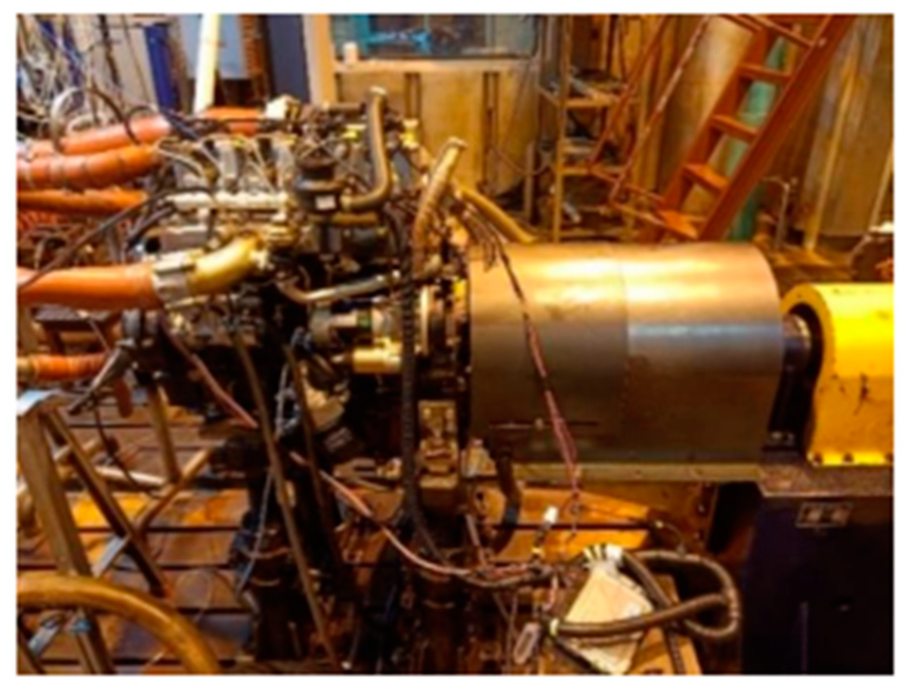
The test engine is a high-pressure common rail four-cylinder diesel engine, model 4B28V16, and the main technical parameters are shown in Table 1. The on-site diagram of the engine is shown in Figure 5.
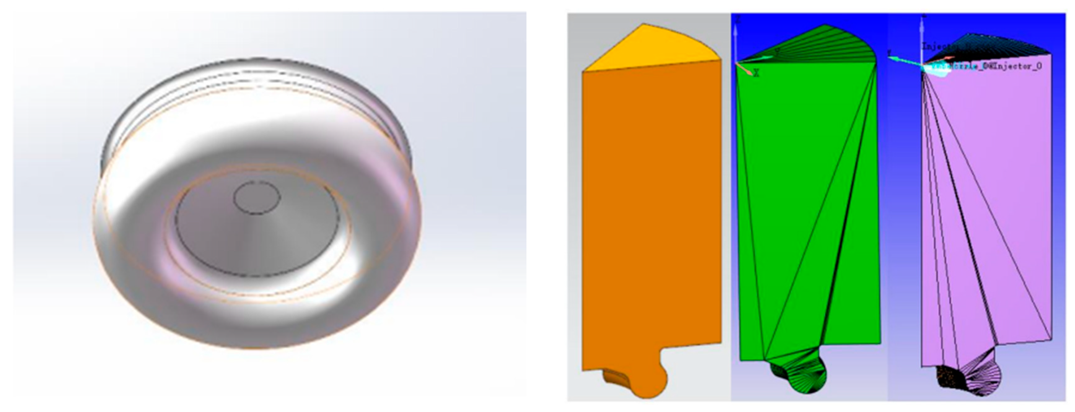
The test prototype adopts a seven-hole injector, which is installed at the center axis of the cylinder, and the seven holes are evenly distributed in the circumferential direction. On the premise of minimizing the computational workload and ensuring the accuracy of the model simulation results, the one-seventh combustion chamber model was selected as the computational domain to carry out the diesel combustion simulation. The one-seventh combustion chamber model was chosen as the computational domain to simulate the combustion process of the diesel engine. Firstly, the three-dimensional combustion chamber model was imported into CONVERGE 2.0 software, and the software was used to simulate the combustion process of the diesel engine. Use the make-surface tool that comes with the software to obtain the ideal orthogonal closed mesh, and then divide the surface mesh into cylinder wall, cylinder surface, and cylinder surface. Then, the surface mesh is divided into cylinder wall, cylinder head, piston, and other boundaries. Figure 6 shows the combustion chamber mesh model, and the boundary conditions for calculation are set as shown in Table 2. Engine simulation calculation shows that the crankshaft angle ranges from −60 °CA to 60 °CA, that is, from the moment the inlet valve is closed to the moment the exhaust valve is opened (the top dead center of the compression stroke is defined as 0 °CA, and a negative angle appears before the top dead center, and vice versa, the angle is positive). Table 2 shows the initial condition for simulation calculation. The initial parameter settings of initial fuel temperature, initial pressure, cylinder head, cylinder wall and combustion chamber top temperature are based on the average temperature and experience.

2.3. Fuel Injection Scheme and Model Verification

To investigate the effect of mixing different proportions of hydrogenated biodiesel and ethanol in diesel on the combustion activity and emissions of diesel engines using multi-stage injection scheme, three ratios of mixed fuels were set: HB5E5 (5% by mass each of hydrogenated biodiesel and ethanol), HB10E10 (10% by mass each), and HB15E15 (15% by mass each). The physical and chemical properties of the fuels used are shown in Table 3. Table 4 shows the structures and cetane number of various fatty acid methyl ester. These esters have very similar structures and are composed of a long alkyl chain attached to the methyl ester group. The difference lies in the number of double bonds in the chain. The cetane number is affected by the number of branch chains, degree of unsaturation degree, isomerization degree, carbon chain length and other factors, and the degree of unsaturation will directly affect the low-temperature oxidation reaction of methyl ester, which is the main reason for the large difference in the cetane number of these lipids. Table 5 shows the components and contents of cottonseed biodiesel and hydrogenated cottonseed biodiesel, which are composed of methyl stearate (C18:0), methyl Palmitic acid (C16:0), and unsaturated fatty acid methyl esters such as methyl oleate (cis-C18:1) and methyl Linoleic acid (C18:2).
Table 6 shows the fuel injection schemes at different blending ratios of hydrogenated biodiesel–ethanol–diesel and at different injection times, set according to experimental data [44]. The in-cylinder combustion simulation work was carried out at an engine speed of 1800 r/min and an average effective pressure of 0.93 MPa. The main parameters of the fuel injection system of the experimental prototype are the injection timing SOI-P1 (Start of 1st Pilot Injection) and SOI-M (Start of Main Injection) for pre injection and main injection, as well as the corresponding injection quantities for the two stages of injection, which are Q1 and QM, respectively.
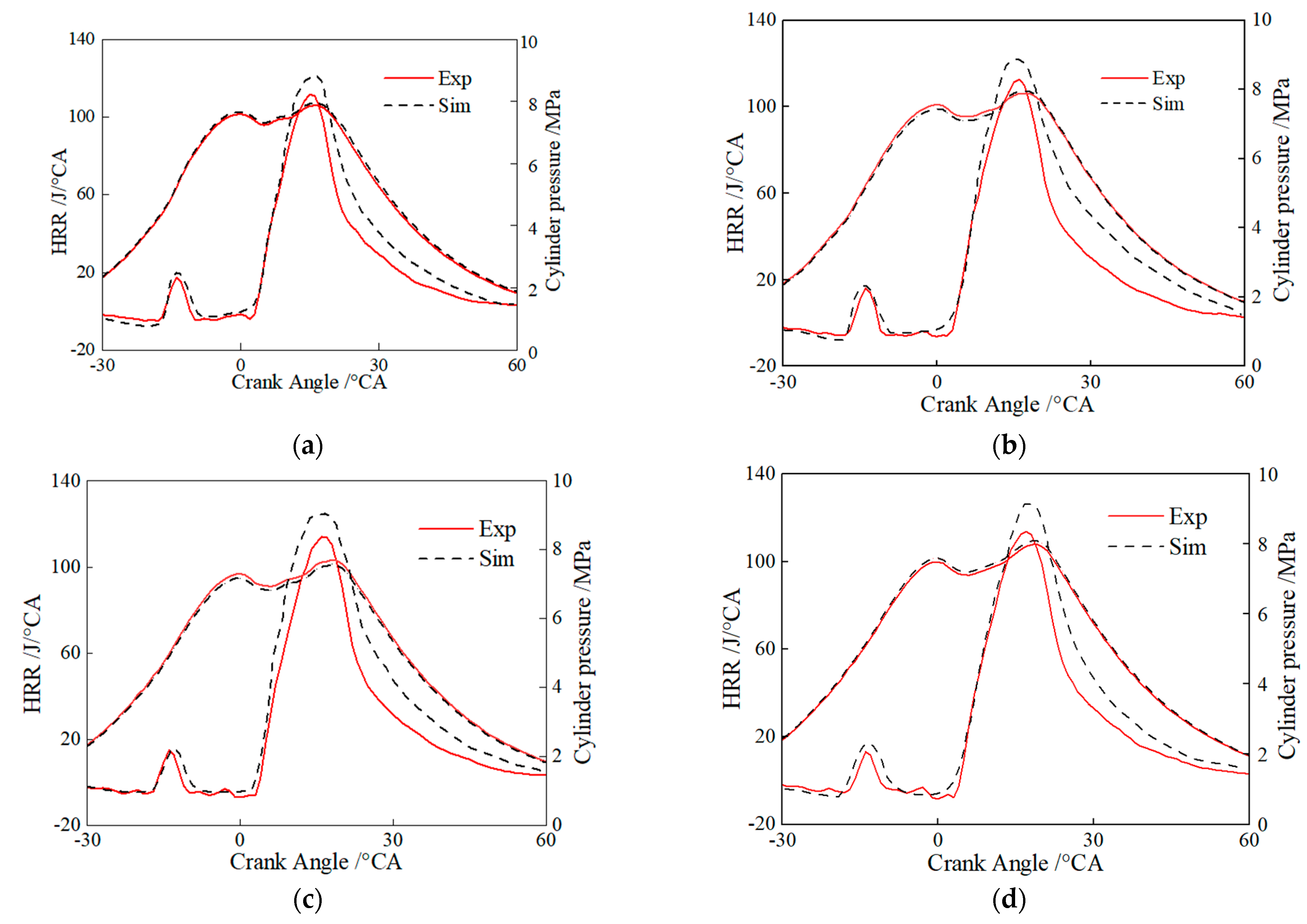
Figure 7 shows the comparison of simulated and experimental in-cylinder pressures and instantaneous heat release rates for the pure diesel, HB5E5, HB10E10, and HB15E15 fuels under the Case 1 fuel injection scheme in Table 4. It can be seen that the hydrogenated biodiesel–ethanol–diesel mixture fuel combustion reaction mechanism model is well coupled with CFD, and it can accurately represent the true combustion and emission performance of the mixed fuel.

3. Results and Analysis

3.1. Analysis of Diesel Engine Combustion Process

Figure 8 shows the cylinder pressure curves of diesel, HB5E5, HB10E10, and HB15E15 fuels under the Case 1 and Case 2 fuel injection schemes. As can be seen, due to the two-stage injection scheme, the cylinder pressure curves of all four fuels consist of two pressure peaks. As a pre-injection–main injection scheme is adopted, the pre-injection fuel amount is smaller, leading to difficulties in the formation of the mixture, resulting in lower in-cylinder temperatures and smaller combustion zones after the pre-injected fuel enters the combustion chamber. HB15E15 fuel reaches the first pressure peak first, with the fastest heat release and the highest peak pressure, followed by HB10E10, HB5E5, and diesel fuel reaching the first pressure peak. Compared to pure diesel, the addition of ester-alcohol leads to a higher peak combustion pressure, which grows larger as the proportion of ester-alcohol increases.
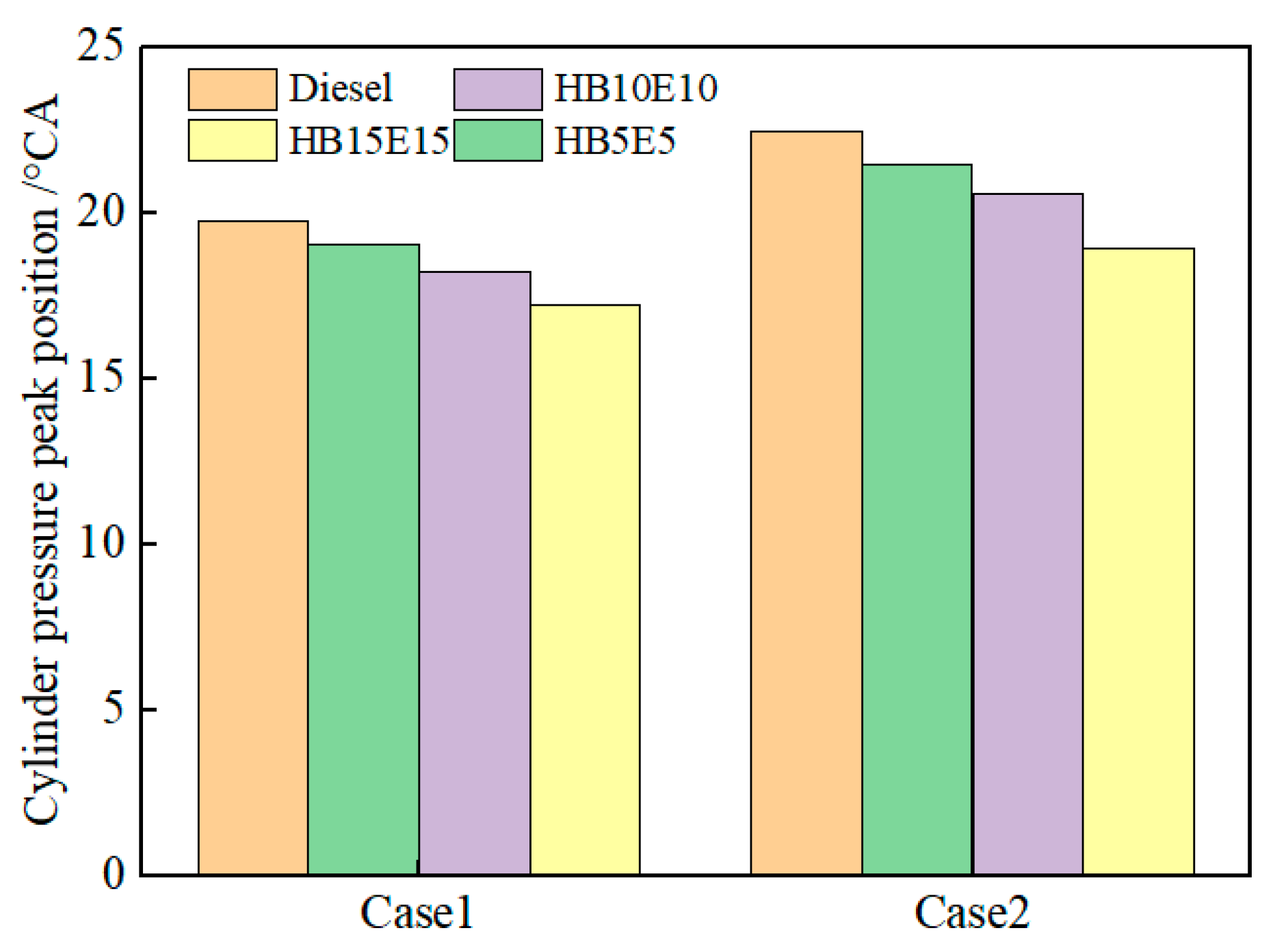
Figure 9 shows the peak pressure positions of diesel, HB5E5, HB10E10, and HB15E15 fuels under the Case 1 and Case 2 fuel injection schemes. As can be observed, adding 15% ester-alcohol advances the in-cylinder pressure peak position, while the peak position for pure diesel is delayed. On one hand, this is related to the fuel’s physicochemical properties. On the other hand, from a chemical kinetics perspective, it is known from the analysis of the cross-reaction flux of the hydrogenated biodiesel–ethanol–diesel mixed fuel at low temperatures that a certain amount of active substance OH is needed to trigger the combustion at the initial stage of combustion of the mixed fuel.
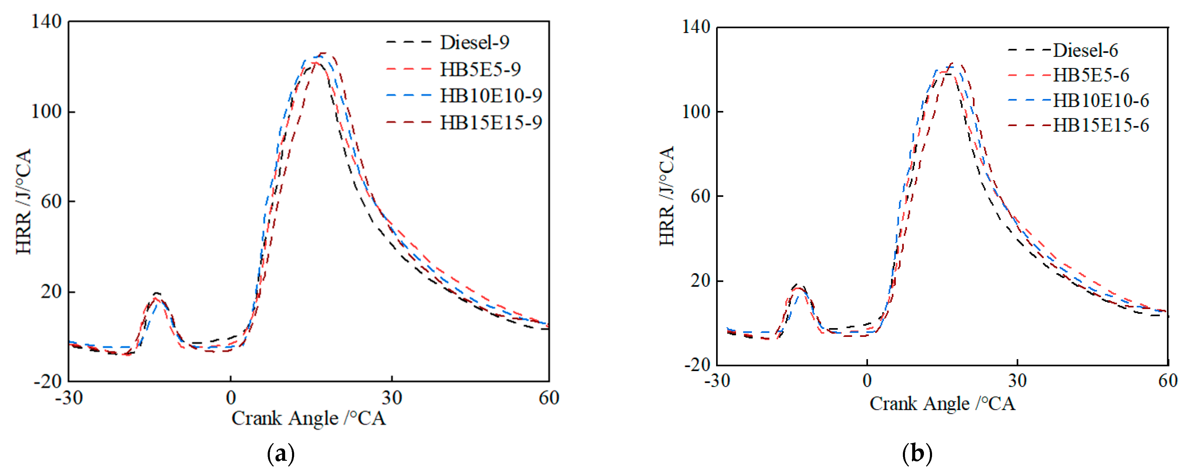
Figure 10 shows the instantaneous heat release rate curves of diesel, HB5E5, HB10E10, and HB15E15 fuels under the Case 1 and Case 2 fuel injection schemes. As can be seen, the heat release rate curves of the four fuels all have two heat release peaks. In the initial heat release stage, the positions of the heat release peaks of the ternary fuels are basically consistent with that of diesel. In the main heat release stage, the heat release peak value of the ternary fuel is significantly delayed and higher than that of diesel.
Figure 11 shows the hydroxyl (OH) generation in pure diesel, HB5E5, HB10E10, and HB15E15 fuels under the Case 1 and Case 2 injection schemes. As observed, with the postponement of the overall injection phase, the generation of OH for all four fuels gradually declines, largely due to the consequential retardation of the primary combustion stage and the decrease in combustion rate, thereby reducing the OH formation. This results in a weakened intra-cylinder combustion reactivity and consequent reduction in cylinder temperature.
Figure 12 shows the evolution curves for hydroperoxyl (HO2), hydrogen peroxide (H2O2) and OH under the Case 2 scheme for diesel, HB5E5, HB10E10, and HB15E15 fuels. It is apparent that around −6 °CA, HO2 and H2O2 are generated nearly simultaneously, signaling the onset of low-temperature reactions. Fuel molecules first undergo oxidation to form HO2, which then partakes in dehydrogenation reactions with other fuel molecules to produce H2O2. From the cross-reaction flow analysis of mixed fuels, it can be inferred that H2O transforms into a more stable H2O2 under low-temperature conditions. As the combustion process advances, H2O2 rapidly decomposes to produce copious OH, enhancing system reactivity and rapidly increasing the temperature of the combustion reaction system. The accumulated peak values of OH for the four fuels are distinct, with pure diesel fuel displaying the least accumulation of OH and HB15E15 fuel showing the highest.

3.2. Emission Generation Characteristics

The primary source of NOx emissions in diesel engines arises from the generation of nitric oxide (NO) in high-temperature areas. Figure 13 illustrates the NOx emission generation curves for pure diesel, HB5E5, HB10E10, and HB15E15 fuels under the Case 1 and Case 2 fuel injection schemes. It is observable that as the injection moment is delayed, the generation of NOx gradually decreases.
Figure 14 shows the in-cylinder NOx emission mass changes under the Case 2 scheme for the four fuels: diesel, HB5E5, HB10E10, and HB15E15. It is evident that among the primary products of NOx emissions, the generation of nitrogen dioxide (NO2) is relatively more than NO. Upon the addition of hydrogenated biodiesel and ethanol, NOx emissions rise across the board. The blended fuel’s hydroxyl (OH) generation exceeds that of pure diesel fuel. A high-temperature, oxygen-rich environment stimulates NOx production, resulting in higher NOx emissions from blended fuels than pure diesel fuel.
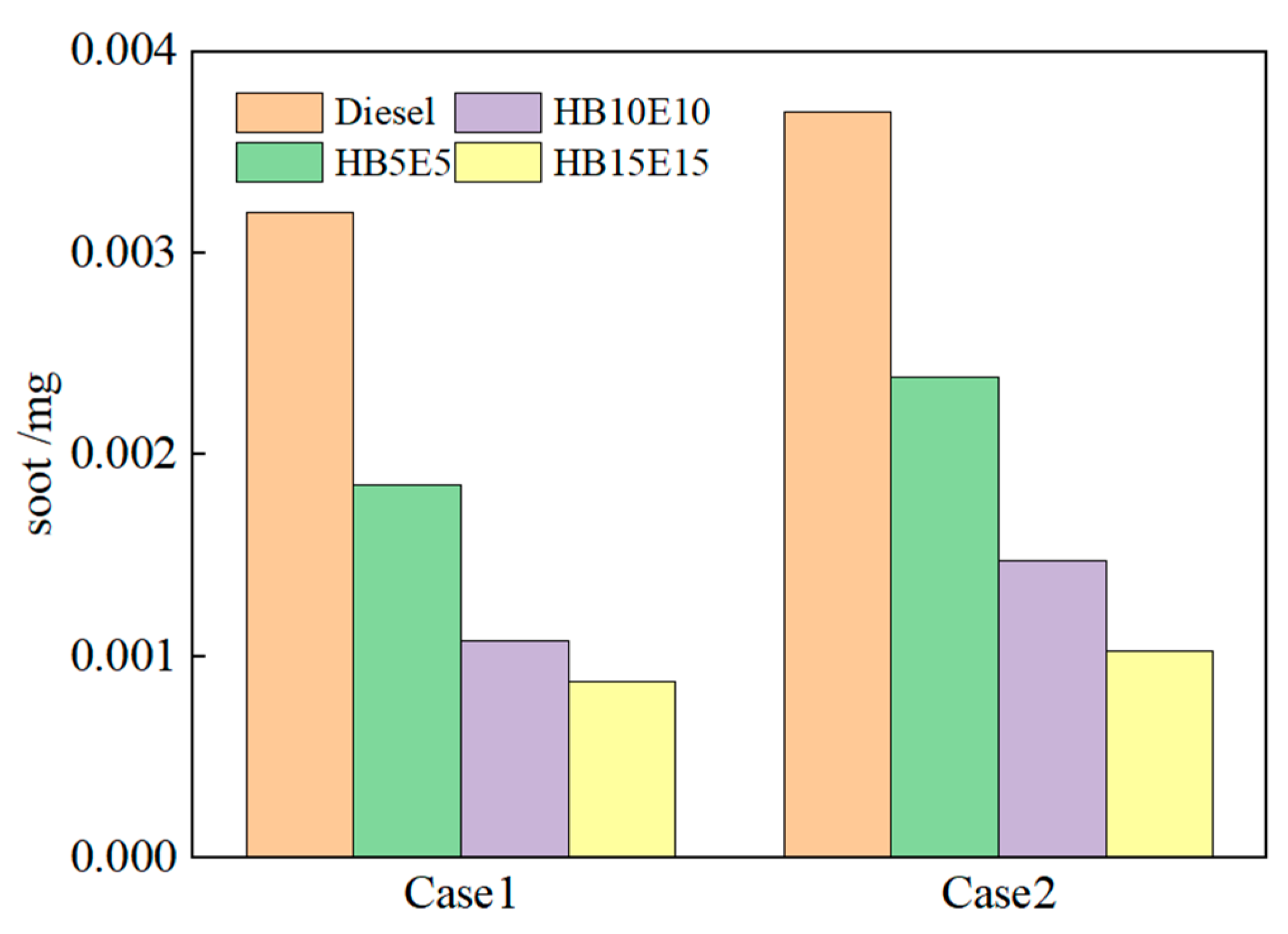
Figure 15 shows the soot generation for diesel, HB5E5, HB10E10, and HB15E15 fuels under the Case 1 and Case 2 injection schemes. As seen, the soot generation is the highest in diesel, which is primarily due to the provision of an oxygen-rich environment by hydrogenated biodiesel and ethanol for the combustion reaction system.
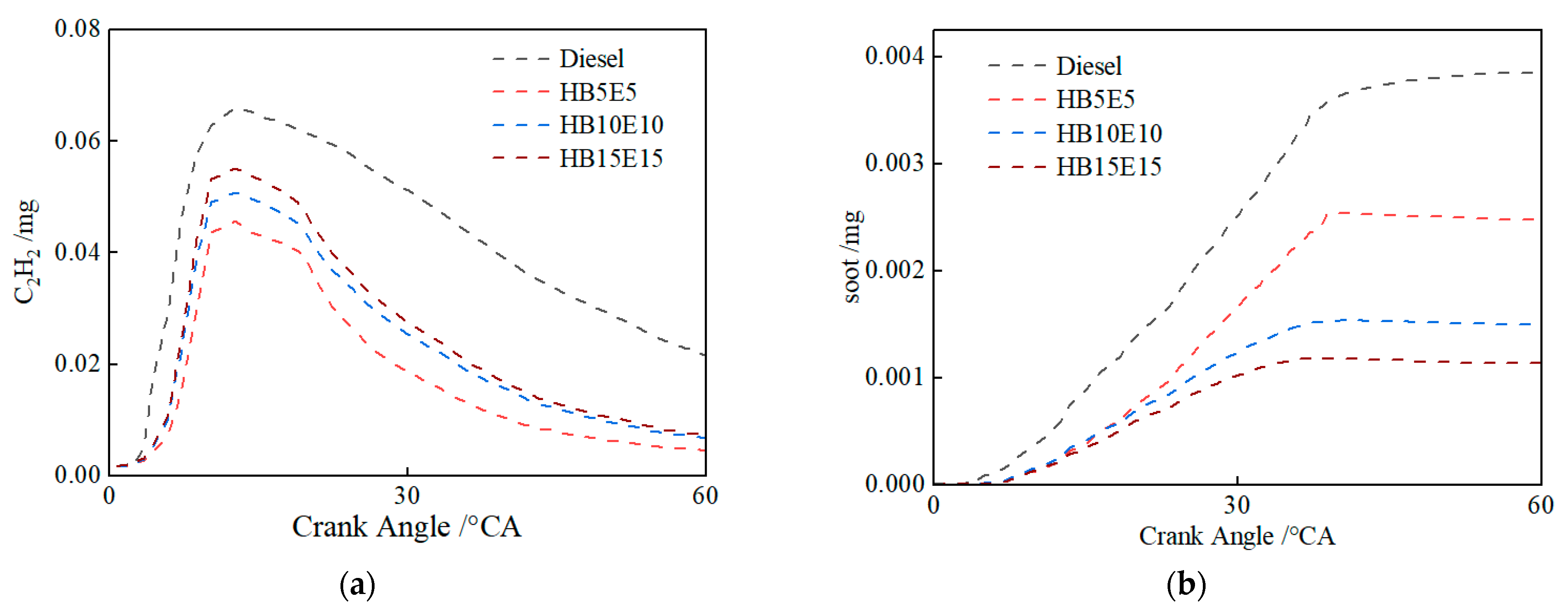
Figure 16 shows the in-cylinder changes in the mass of soot precursors C2H2, and soot emissions under the Case 2 scheme for the four fuels: diesel, HB5E5, HB10E10, and HB15E15. In comparison to diesel, the high oxygen content of blended fuels enhances opportunities for oxygen interaction, thus curtailing soot production stemming from oxygen-deficient mixtures. The generation of soot is significantly impacted by hydroxyl (OH). As can be inferred from Figure 9, the generation of OH has diminished under the Case 2 scheme relative to the Case 1 scheme, leading to a decrease in in-cylinder combustion reaction activity. Consequently, soot oxidation is restricted, culminating in an uptick in soot generation.

4. Conclusions

(1)
The addition of ester-alcohol fuel augments in-cylinder combustion reaction activity, promoting the progression of in-cylinder combustion. Furthermore, as the blending ratio of ester-alcohol fuel increases, the advance of the heat release center, CA50, becomes more pronounced. Due to the superior volatility of ethanol, which stimulates the progression of in-cylinder combustion, the peak values of the maximum combustion pressure and instantaneous heat release rate for HB5E5, HB10E10, and HB15E15 fuels surpass that of pure diesel.
(2)
After the inclusion of ester-alcohol, the NOx emission generation volume of blended fuels escalates in comparison to pure diesel. This increase becomes more significant as the blending ratio of hydrogenated biodiesel and ethanol heightens.
(3)
After the addition of ester-alcohol, the soot generation volume of blended fuels significantly diminishes relative to pure diesel. It is primarily distributed in areas with high equivalence ratios and high temperatures. The distribution of acetylene (C2H2) in-cylinder is approximately similar to soot. This phenomenon primarily stems from the high oxygen content of blended fuels, increasing the chance of diesel-oxygen contact, thereby reducing soot production due to oxygen-deficient mixtures.

Author Contributions

Conceptualization, J.Z.; Data curation, J.Z.; Formal analysis, W.X.; Funding acquisition, J.Z.; Investigation, R.Z.; Methodology, J.Z. and W.Z.; Project administration, W.Z.; Resources, R.Z.; Software, W.X. and R.Z.; Supervision, W.Z.; Validation, J.Z.; Writing—original draft, J.Z.; Writing—review and editing, J.Z. and W.Z. All authors have read and agreed to the published version of the manuscript.

Funding

This research was funded by the Hunan Provincial Natural Science Foundation (Grant No. 2022JJ60090), Belt and Road Project in Jiangsu Province (Grant No. BZ2022016) and Scientific research project of Department of Education of Hunan Province (Grant No. 21C1577).

Data Availability Statement

The data that support the findings of this study are available from the corresponding author upon reasonable request.

Conflicts of Interest

The authors declare no conflict of interest.

References

  1. Xu, Z. Trends in the Development of Traditional Fossil Energy and New Energy Under the “Dual Carbon” Goal. Petrochem. Ind. Technol. 2022, 29, 188–190. [Google Scholar]
  2. Min, J. Current Status and Prospects of Advanced Bio-Liquid Fuels. Green Low Carbon Petrochem. Green Pet. Petrochem. 2023, 8, 22–27. [Google Scholar]
  3. Kesharvani, S.; Verma, T.N.; Gaurav, D. Computational analysis of chlorella protothecoides biofuels on engine combustion, performance and emission. Sustain. Energy Technol. Assess. 2023, 55, 102972. [Google Scholar] [CrossRef]
  4. Szwaja, S.; Gruca, M.; Pyrc, M.; Juknelevičius, R. Glycerol as an Anti-Knock Additive and Secondary Fuel as a Substitute for Gasoline-Based Fuels for the IC Engine. Energies 2023, 16, 4940. [Google Scholar] [CrossRef]
  5. Zhou, J.; He, Y.; Lyu, Y.; Wang, K.; Che, Y.; Wang, X. Long-Term Electricity Forecasting for the Industrial Sector in Western China Under the Carbon Peaking and Carbon Neutral Targets. Energy Sustain. Dev. 2023, 73, 174–178. [Google Scholar] [CrossRef]
  6. Li, P.; Sun, W.; Zhang, Z.; He, Y.; Wang, Y. Forecast of Renewable Energy Penetration Potential in the Goal of Carbon Peaking and Carbon Neutrality in China. Sustain. Prod. Consum. 2022, 34, 541–551. [Google Scholar] [CrossRef]
  7. Szelangiewicz, T.; Żelazny, K. Reducing CO2 Emissions during the Operation of Unmanned Transport Vessels with Diesel Engines. Energies 2023, 16, 4818. [Google Scholar] [CrossRef]
  8. Li, R. Integrating the Composition of Food Waste into the Techno-Economic Analysis of Waste Biorefineries for Biodiesel Production. Bioresour. Technol. Rep. 2022, 20, 2589–2597. [Google Scholar]
  9. Mubarak, M.; Shaija, A.; Suchithra, T.V. Experimental Evaluation of Salvinia Molesta Oil Biodiesel/Diesel Blends Fuel on Combustion Performance and Emission Analysis of Diesel Engine. Fuel 2021, 287, 119526. [Google Scholar] [CrossRef]
  10. Molière, M. The Fuel Flexibility of Gas Turbines: A Review and Retrospective Outlook. Energies 2023, 16, 3962. [Google Scholar] [CrossRef]
  11. Rojas-Reinoso, V.; Duque-Escobar, S.; Guapulema-Guapulema, C.; Soriano, J.A. Study of the Variation of Fuel Pressure to Improve Spraying and the Range of the Injection Jet. Energies 2023, 16, 5472. [Google Scholar] [CrossRef]
  12. Singh, D.; Sharma, D.; Soni, S.L.; Inda, C.S.; Sharma, S.; Sharma, P.K.; Jhalani, A. A comprehensive review of physicochemical properties, production process, performance and emissions characteristics of 2nd generation biodiesel feedstock: Jatropha curcas. Fuel 2021, 285, 119110. [Google Scholar] [CrossRef]
  13. Yin, G.; Xiao, B.; Hu, E.; Huang, Z. Automatic Optimization of Acetic Acid Chemical Reaction Kinetics Model Using Neural Network and Bayesian Inversion Method. J. Xi’an Jiaotong Univ. 2023, 57, 130–138. [Google Scholar]
  14. Ding, Y.; Ezekoye, O.A.; Zhang, J.Q.; Wang, C.; Lu, S. The Effect of Chemical Reaction Kinetic Parameters on the Bench-Scale Pyrolysis of Lignocellulosic Biomass. Fuel 2018, 232, 147–153. [Google Scholar] [CrossRef]
  15. Telli, G.D.; Zu, G.Y.; Lanzanova, T.D.M.; Martins, M.E.S.; Rocha, L.A.O. An Experimental Study of Performance, Combustion and Emissions Characteristics of an Ethanol HCCI Engine Using Water Injection. Appl. Therm. Eng. 2022, 204, 118003. [Google Scholar] [CrossRef]
  16. Singh, D.; Sharma, D.; Soni, S.L.; Sharma, S.; Sharma, P.K.; Jhalani, A. A Review of Feedstocks, Production Processes, and Yield for Different Generations of Biodiesel. Fuel 2020, 262, 116553. [Google Scholar] [CrossRef]
  17. Zhang, W.; Han, L. Current Status and Development Trend of Biodiesel Research at Home and Abroad. Chem. Eng. Manag. 2021, 12, 72–73. [Google Scholar]
  18. Shi, W.; Li, J.; He, B.; Yan, F.; Cui, Z.; Wu, K.; Lin, L.; Qian, X.; Cheng, Y. Biodiesel Production from Waste Chicken Fat with Low Free Fatty Acids by an Integrated Catalytic Process of Composite Membrane and Sodium Methoxide. Bioresour. Technol. 2013, 139, 316–322. [Google Scholar] [CrossRef]
  19. Szabados, G.; Bereczky, Á. Experimental Investigation of Physicochemical Properties of Diesel, Biodiesel and TBK-Biodiesel Fuels and Combustion and Emission Analysis in CI Internal Combustion Engine. Renew. Energy 2018, 121, 568–578. [Google Scholar] [CrossRef]
  20. Nabin, M.; Rasul, M.G.; Anwar, M.; Mullins, B. Emission and Combustion Characteristics of Diesel Engine Using New Series of Non-Edible Biodiesels. Renew. Energy 2019, 140, 647–657. [Google Scholar] [CrossRef]
  21. Martos, F.J.; Soriano, J.A.; Braic, A.; Fernández-Yáñez, P.; Armas, O. A CFD Modelling Approach for the Operation Analysis of an Exhaust Backpressure Valve Used in a Euro 6 Diesel Engine. Energies 2023, 16, 4112. [Google Scholar] [CrossRef]
  22. Sathyamurthy, R.; Balaji, D.; Gorjian, S.; Muthiya, S.J.; Bharathwaaj, R.; Vasanthaseelan, S.; Essa, F.A. Performance Combustion and Emission Characteristics of a DI-CI Diesel Engine Fueled with Corn Oil Methyl Ester Biodiesel Blends. Sustain. Energy Technol. Assess. 2021, 43, 100981. [Google Scholar] [CrossRef]
  23. Aydn, S. Comprehensive Analysis of Combustion, Performance and Emissions of Power Generator Diesel Engine Fueled with Different Source of Biodiesel Blends. Energy 2020, 205, 118074. [Google Scholar] [CrossRef]
  24. Knothe, G. Analysis of Oxidized Biodiesel by 1H-NMR and Effect of Contact Area with Air. Eur. J. Lipid Sci. Technol. 2006, 108, 493–500. [Google Scholar] [CrossRef]
  25. Cravero, C.; Marsano, D. Numerical Simulation of Melted Glass Flow Structures inside a Glass Furnace with Different Heat Release Profiles from Combustion. Energies 2023, 16, 4187. [Google Scholar] [CrossRef]
  26. Sun, W.; Zheng, C.; Gou, X.; Ju, Y. A Path Flux Analysis Method for the Reduction of Detailed Chemical Kinetic Mechanisms. Combust. Flame 2010, 157, 1298–1307. [Google Scholar] [CrossRef]
  27. Sx, A.; Jie, X.B.; Fan, W.B.; Li, X. Reduction of Large-Size Combustion Mechanisms of n-Decane and n-Dodecane with an Improved Sensitivity Analysis Method. Combust. Flame 2020, 222, 326–335. [Google Scholar]
  28. Tamas, T. Applications of Sensitivity Analysis to Combustion Chemistry. Reliab. Eng. Syst. Saf. 1997, 57, 41–48. [Google Scholar]
  29. Qi, P. Study on the Kinetic Mechanism of Low-Temperature Combustion in Diesel Engines. Ph.D. Thesis, Tianjin University, Tianjin, China, 2017. [Google Scholar]
  30. Aklouche, F.Z.; Hadhoum, L.; Loubar, K.; Tazerout, M. A Comprehensive Study on Effect of Biofuel Blending Obtained from Hydrothermal Liquefaction of Olive Mill Waste Water in Internal Combustion Engine. Energies 2023, 16, 2534. [Google Scholar] [CrossRef]
  31. Westbrook, C.K.; Naik, C.V.; Herbinet, O.; Pitz, W.; Mehl, M. Detailed Chemical Kinetic Reaction Mechanism for Biodiesel Components Methyl Stearate and Methyl Oleate. Proc. Combust. Inst. 2011, 33, 383–389. [Google Scholar]
  32. Campbell, M.F.; Davidson, D.F.; Hanson, R.K.; Westbrook, C. Ignition Delay Times of Methyl Oleate and Methyl Linoleate Behind Reflected Shock Waves. Proc. Combust. Inst. 2013, 34, 419–425. [Google Scholar] [CrossRef]
  33. Sarathy, S.M.; Gaïl, S.; Syed, S.A.; Thomson, M.; Dagaut, P. A Comparison of Saturated and Unsaturated C4 Fatty Acid Methyl Esters in an Opposed Flow Diffusion Flame and a Jet Stirred Reactor. Proc. Combust. Inst. 2007, 31, 1015–1022. [Google Scholar] [CrossRef]
  34. Wang, W.J.; Oehlschlaeger, M.A. A Shock Tube Study of Methyl Decanoate Autoignition at Elevated Pressures. Combust. Flame 2012, 159, 476–481. [Google Scholar] [CrossRef]
  35. Glaude, P.E.; Herbinet, O.; Bax, S.; Biet, J.; Warth, V.; Battin-Leclerc, F. Modeling of the Oxidation of Methyl Esters—Validation for Methyl Hexanoate, Methyl Heptanoate, and Methyl Decanoate in a Jet-Stirred Reactor. Combust. Flame 2010, 157, 2035–2050. [Google Scholar] [CrossRef]
  36. Xu, L. Numerical and Experimental Study of Fuel Injection, Stratified Mixture and Combustion Characteristics under Low-Temperature Combustion Mode. Ph.D. Thesis, Shanghai Jiao Tong University, Shanghai, China, 2019. [Google Scholar]
  37. Zhao, Z. Experimental Study on Combustion and Emission Characteristics of Ethanol/Gasoline/Brown Gas Ternary Fuel Compound Supplied Engine. Ph.D. Thesis, Jilin University, Jilin, China, 2022. [Google Scholar]
  38. Sun, M. Numerical Calculation Study on the Impact of Multiple Injection Strategies on Engine Combustion and Emission of Biodiesel. Ph.D. Thesis, Huazhong University of Science and Technology, Wuhan, China, 2016. [Google Scholar]
  39. He, J. Simulation Study on the Impact of Multi-Stage Injection on Engine Performance when Using B20 Biodiesel. Ph.D. Thesis, Southwest Jiaotong University, Chengdu, China, 2019. [Google Scholar]
  40. Wang, H. Combustion Characteristics and Simulation Analysis of Waste Cooking Oil and its Biodiesel in Industrial Furnace. Ph.D. Thesis, Kunming University of Science and Technology, Kunming, China, 2018. [Google Scholar]
  41. Li, J.; Li, M.; Zeng, L.; Zhang, Z. Application of Combustion Simulation in the Development of Combustion System for National Six Diesel Engine. Veh. Engine 2021, 252, 40–44. [Google Scholar]
  42. Vaughn, T.; Hammill, M.; Harris, M.; Marchese, A. Ignition Delay of Bio-Ester Fuel Droplets. SAE Tech. Pap. 2006, 1, 3302. [Google Scholar]
  43. Fieweger, K.; Blumenthal, R.; Adomeit, G. Self-Ignition of SI Engine Model Fuels: A Shock Tube Investigation at High Pressure. Combust. Flame 1997, 109, 599–619. [Google Scholar] [CrossRef]
  44. Zuo, L. Study on Combustion and Emission Characteristics of Diesel Engines Fueled with Hydrogenated Biodiesel-Ethanol-Diesel. Ph.D. Thesis, Jiangsu University, Zhenjiang, China, 2020. [Google Scholar]
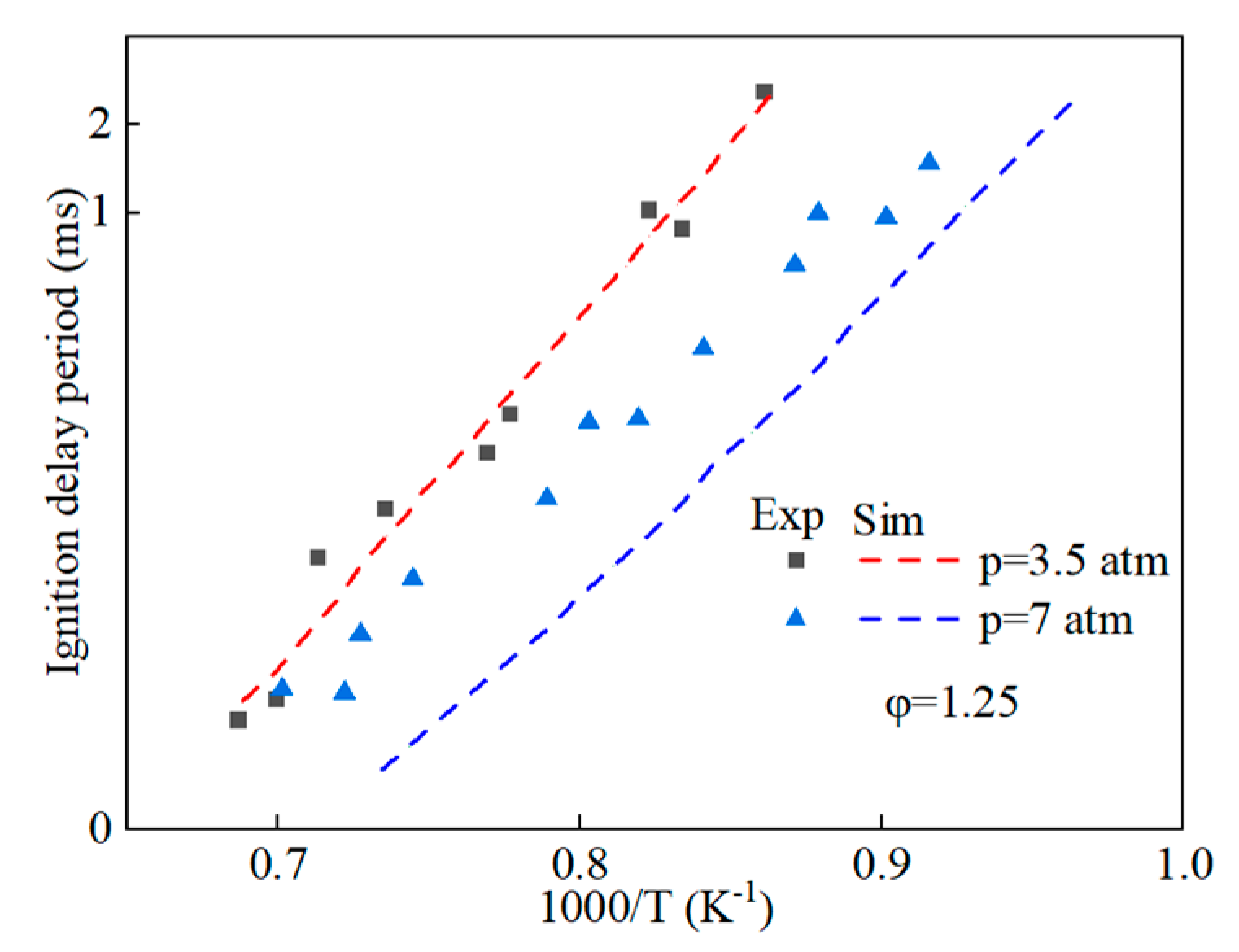
Figure 1. Comparison of ignition delay periods predicted by simplified mechanisms of methyl oleate with experimental values.
Energies 16 06093 g001
Figure 2. Comparison of ignition delay periods predicted by simplified mechanisms of methyl stearate with experimental values.
Energies 16 06093 g002
Figure 3. Comparison of ignition delay period predicted by simplified mechanism of hydrogenated bio-diesel with experimental values.
Energies 16 06093 g003
Figure 4. Comparison of ignition delay periods predicted by n-heptane-ethanol mixed mechanism with experimental values.
Energies 16 06093 g004
Figure 5. The field view of engine bench.
Energies 16 06093 g005
Figure 6. The shape and meshing of the combustion chamber.
Energies 16 06093 g006
Figure 7. Comparison of simulated cylinder pressures and heat release rates with the experimental result for different fuels. (a) Diesel; (b) HB5E5; (c) HB10E10; (d) HB15E15.
Energies 16 06093 g007
Figure 8. Cylinder pressure curves of different fuels under various injection schemes. (a) Case 1; (b) Case 2.
Energies 16 06093 g008
Figure 9. Peak pressure positions of various fuels under Case 1 and Case 2 injection schemes.
Energies 16 06093 g009
Figure 10. Instantaneous heat release rate curves of various fuels under Case 1 and Case 2 schemes. (a) Case 1; (b) Case 2.
Energies 16 06093 g010
Figure 11. OH generation of various fuels under Case 1 and Case 2 schemes.
Energies 16 06093 g011
Figure 12. HO2, H2O2, and OH generation of various fuels under Case 2 scheme. (a) HO2; (b) H2O2; (c) OH.
Energies 16 06093 g012
Figure 13. NOx emission generation of various fuels under Case 1 and Case 2 schemes.
Energies 16 06093 g013
Figure 14. NO2, NOx, and NO emissions of various fuels under Case 2 scheme. (a) NO2; (b) NOx; (c) NO.
Energies 16 06093 g014
Figure 15. Soot generation of various fuels under Case 1 and Case 2 schemes.
Energies 16 06093 g015
Figure 16. Changes in the mass of C2H2 and soot in-cylinder of various fuels under Case 2 scheme. (a) C2H2; (b) soot.
Energies 16 06093 g016
Table 1. Main technical parameters of 4B28V16 diesel engine.
ItemParameter
Number of cylinders4
Cylinder diameter95 mm
Piston stroke100 mm
Total piston displacement2.83 L
Calibrated power75 kW
Calibrated speed3200 r/min
Maximum torque250 N·m
Maximum speed1600~2800 r/min
Table 2. Initial conditions and boundary parameters.
Initial ConditionBoundary Parameter
Cylinder wall temperature407 K
Cylinder head temperature450 K
Combustion chamber top temperature478 K
Initial pressure1.8 MPa
Initial temperature403 K
Table 3. Physical and chemical properties of fuels.
Fuel PropertiesMolecular FormulaOxygen-Containing Functional GroupsCetaneLower Calorific ValueOxygen Content
n-HeptanenC7H16/5441.8 MJ/kg0
Hydrogenated biodieselC19H36.4O2Energies 16 06093 i00171.238.42 MJ/kg9.3
EthanolC2H5OHEnergies 16 06093 i0023515.78 MJ/kg53.4
Table 4. Structure and cetane number of fatty acid methyl esters.
Lipid Structure Cetane NumberLipid Structure Cetane NumberLipid Structure Cetane Number
Methyl Palmitic acidEnergies 16 06093 i00386
Methyl stearateEnergies 16 06093 i004104.1
Methyl oleateEnergies 16 06093 i00562.3
Methyl Linoleic acidEnergies 16 06093 i00638
Methyl linolenic acidEnergies 16 06093 i00723
Table 5. Compositions of cottonseed methyl ester and hydrogenated cottonseed methyl ester.
Number Retention
Time
Min ComponentNameMolecular FormulaPeak Area/%
CMEPHCME
114.61methyl myristate (C14:0)C15H30O20.130.12
217.23methyl palmitate (C16:0)C17H34O223.0523.07
321.19methyl stearate (C18:0)C19H38O23.1713.25
421.66Elaidic acid methyl ester (trans-C18:1)C19H36O2015.47
521.91Cis oleic acid methyl ester (cis-C18:1)C19H36O221.4730.48
623.18Linoleic acid methyl ester (C18:2)C19H34O249.9416.06
724.65Methyl linolenic acid (C18:3)C19H32O21.560.87
825.89Arachidic acid methyl ester (C20:0)C21H42O20.530.55
930.79Behenic acid methyl ester (C22:0)C23H46O20.150.13
Table 6. Schemes of fuel injection.
CaseSchemeSOI-P1SOI-MQMQ1
Case 1Diesel-9−28 °CA−9 °CA43 mg1.2 mg
HB5E5-9−28 °CA−9 °CA43 mg1.2 mg
HB10E10-9−28 °CA−9 °CA43 mg1.2 mg
HB15E15-9−28 °CA−9 °CA43 mg1.2 mg
Case 2Diesel-6−25 °CA−6 °CA43 mg1.2 mg
HB5E5-6−25 °CA−6 °CA43 mg1.2 mg
HB10E10-6−25 °CA−6 °CA43 mg1.2 mg
HB15E15-6−25 °CA−6 °CA43 mg1.2 mg
Disclaimer/Publisher’s Note: The statements, opinions and data contained in all publications are solely those of the individual author(s) and contributor(s) and not of MDPI and/or the editor(s). MDPI and/or the editor(s) disclaim responsibility for any injury to people or property resulting from any ideas, methods, instructions or products referred to in the content.