
DC Circuit Breaker Evolution, Design, and Analysis


Abstract
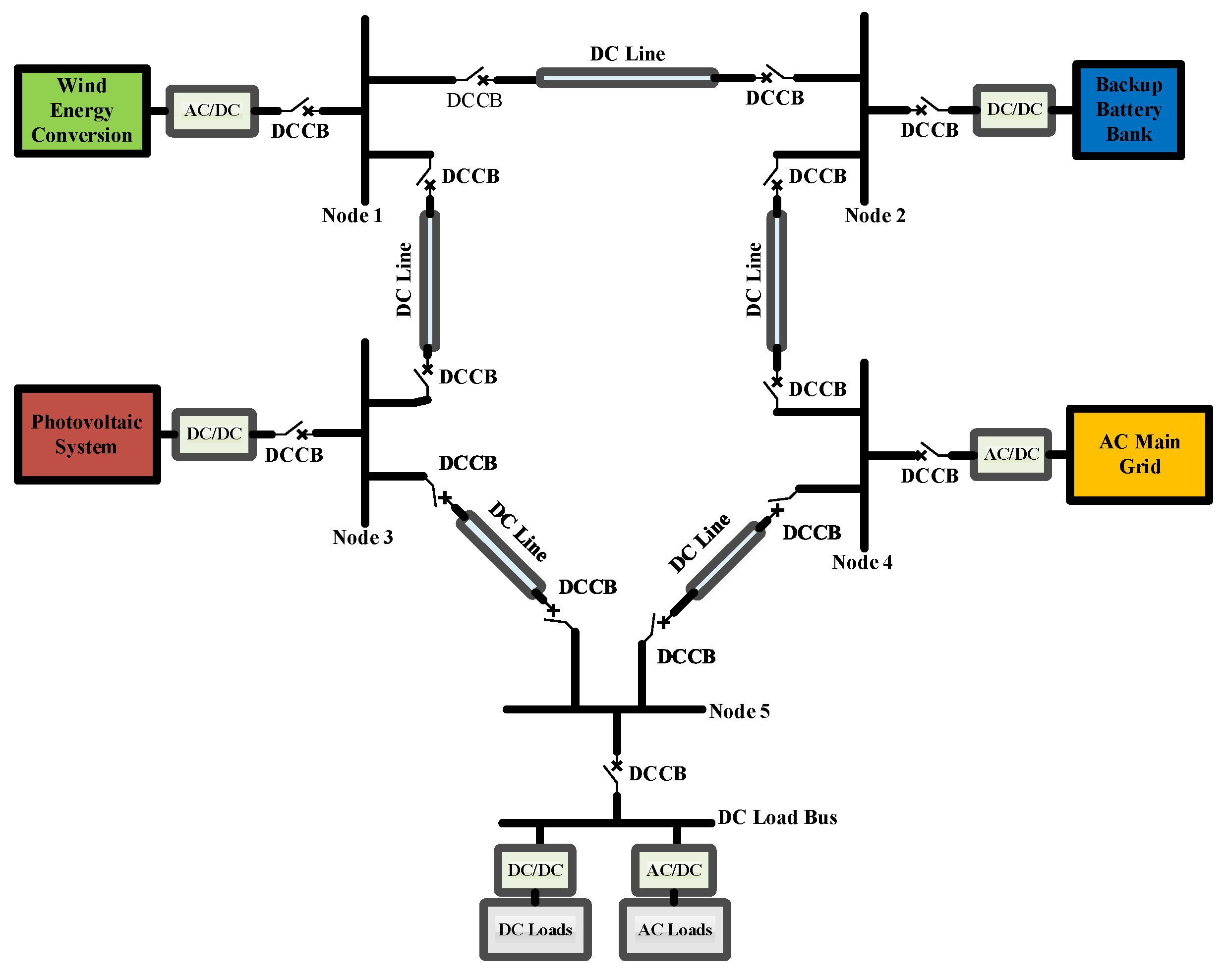
:1. Introduction
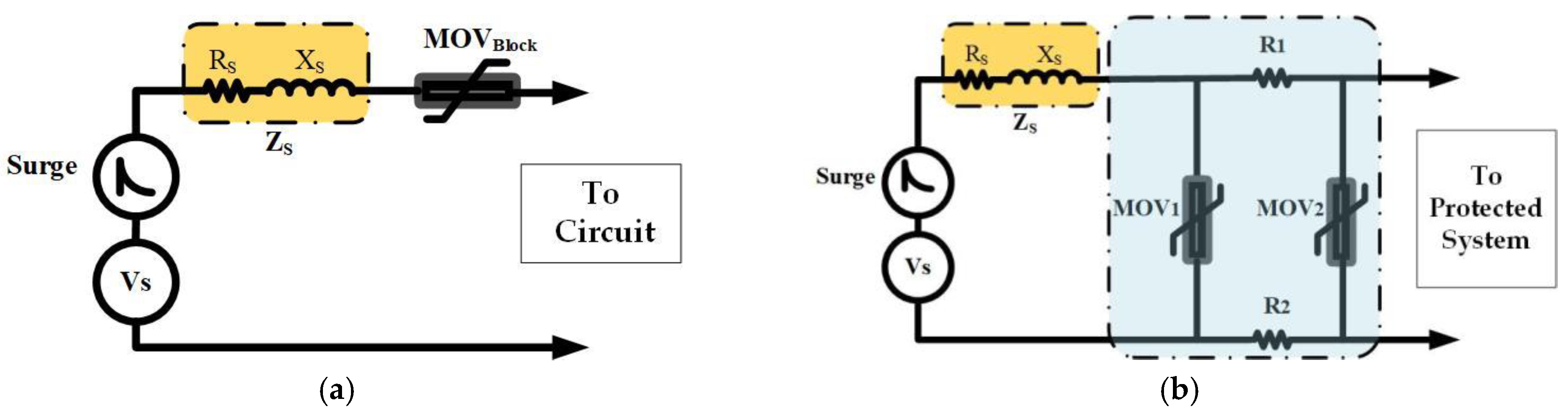
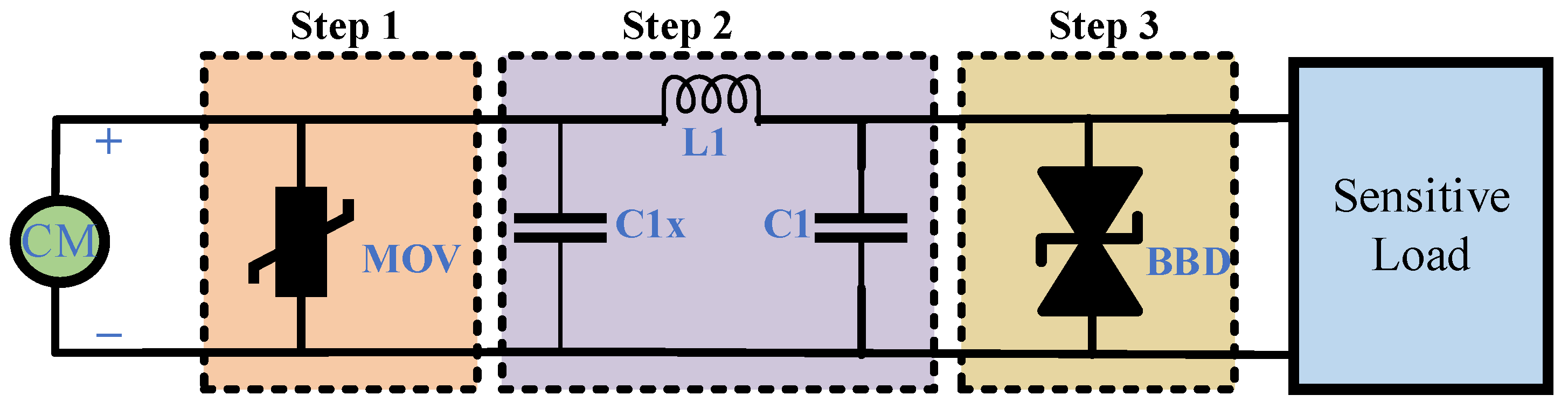
2. Surge Absorption Design Principle for DC Circuits
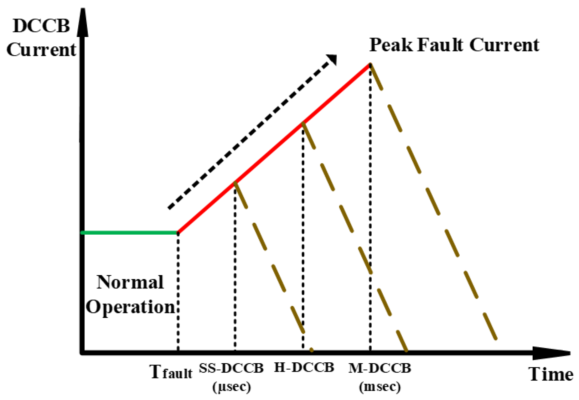
3. DC Circuit Breaker Topologies
- mechanical (resonance) DC circuit breakers (M-DCCB);
- solid-state (static) DC circuit breakers (SS-DCCB);
- hybrid DC circuit breakers (H-DCCB).
- the normal current flow line;
- the forced current diverted commutation line;
- the surge mitigation subcircuit.
4. Design Improvements of DCCBs for DC Microgrid Application
- 4.1.
- MOV-based DCCBs;
- 4.2.
- capacitor-based DCCBs;
- 4.3.
- hybrid MOV–Cap DCCBs.
4.1. MOV-Based DCCBs
4.2. Capacitor-Based DCCBs
4.3. Hybrid MOV–Cap DCCBs
5. Design Improvements
6. Prospective Future Advancement
- The surge absorption techniques and subcircuits in DCCB design can be studied to cover the existing limitations.
- The DCCB designs can be integrated in terms of performance and a higher breaking capacity against the faults and switching of DC circuits.
- The reliability and lifetime of DCCBs can be improved by using non-chemical, non-degradable components for surge, fault, and switching effect absorption.
- Costs can be reduced by substituting a minimal amount of degradable components, and alternative components, such as resistance, can be used instead of expensive ones, such as MOVs.
- Power loss can be minimized through design improvements, which could involve reducing both switching power loss resulting from semiconductor switching and passive component loss from elements such as current limiters and snubber resistors during regular system operations. This can lead to a more efficient performance with reduced power dissipation.
7. Conclusions
Author Contributions
Funding
Data Availability Statement
Acknowledgments
Conflicts of Interest
References
- Rezk, H.; Ghoniem, R.M.; Ferahtia, S.; Fathy, A.; Ghoniem, M.M.; Alkanhel, R. A Comparison of Different Renewable-Based DC Microgrid Energy Management Strategies for Commercial Buildings Applications. Sustainability 2022, 14, 16656. [Google Scholar] [CrossRef]
- Lotfi, H.; Khodaei, A. Hybrid AC/DC microgrid planning. Energy 2017, 118, 37–46. [Google Scholar] [CrossRef]
- Papari, B.; Edrington, C.S.; Bhattacharya, I.; Radman, G. Effective Energy Management of Hybrid AC–DC Microgrids with Storage Devices. IEEE Trans. Smart Grid 2019, 10, 193–203. [Google Scholar] [CrossRef]
- Vuyyuru, U.; Maiti, S.; Chakraborty, C. Active Power Flow Control Between DC Microgrids. IEEE Trans. Smart Grid 2019, 10, 5712–5723. [Google Scholar] [CrossRef]
- Jain, D.; Saxena, D. Comprehensive review on control schemes and stability investigation of hybrid AC-DC microgrid. Electr. Power Syst. Res. 2023, 218, 109182. [Google Scholar] [CrossRef]
- Baidya, S.; Nandi, C. A comprehensive review on DC Microgrid protection schemes. Electr. Power Syst. Res. 2022, 210, 108051. [Google Scholar] [CrossRef]
- Montoya, R.; Poudel, B.P.; Bidram, A.; Reno, M.J. DC microgrid fault detection using multiresolution analysis of traveling waves. Electr. Power Energy Syst. 2022, 135, 107590. [Google Scholar] [CrossRef]
- Bayati, N.; Balouji, E.; Baghaee, H.R.; Hajizadeh, A.; Soltani, M.; Lin, Z.; Savaghebi, M. Locating high-impedance faults in DC microgrid clusters using support vector machines. Appl. Energy 2022, 308, 118338. [Google Scholar] [CrossRef]
- Ibrahim, M.H.; Badran, E.A.; Abdel-Rahman, M.H. On the DC Microgrids Protection Challenges, Schemes, and Devices—A Review. In DC Microgrids: Advances, Challenges, and Applications; Wiley: Hoboken, NJ, USA, 2022. [Google Scholar] [CrossRef]
- Zhang, Q.; Hu, W.; Liu, Y.; Zhang, H.; Wang, H. A novel smooth switching control strategy for multiple photovoltaic converters in DC microgrids. J. Power Electron. 2022, 22, 163–175. [Google Scholar] [CrossRef]
- Available online: https://new.abb.com/low-voltage/products/circuit-breakers (accessed on 27 March 2023).
- Available online: https://www.se.com/ww/en/product-range/44215156-compact-for-dc-networks-new-generation (accessed on 27 March 2023).
- Available online: https://www.eaton.com/nz/en-gb/products/electrical-circuit-protection/circuit-breakers.html (accessed on 27 March 2023).
- Available online: https://www.siemens.com/global/en/products/energy/low-voltage/components/sentron-protection-devices.html (accessed on 27 March 2023).
- Available online: https://www.ls-electric.com/products/category/Smart_Power_Solution/DC_Component (accessed on 27 March 2023).
- Huo, Q.; Xiong, J.; Zhang, N.; Guo, X.; Wu, L.; Wei, T. Review of DC circuit breaker application. Electr. Power Syst. Res. 2022, 209, 107946. [Google Scholar] [CrossRef]
- Corzine, K.A. Circuit Breaker for DC Micro Grids. In Proceedings of the IEEE First International Conference on DC Microgrids (ICDCM), Atlanta, GA, USA, 7–10 June 2015. [Google Scholar] [CrossRef]
- Maqsood, A.; Corzine, K.A. DC Microgrid Protection: Using the Coupled-Inductor Solid-State Circuit Breaker. IEEE Electrif. Mag. 2016, 4, 58–64. [Google Scholar] [CrossRef]
- Bayati, N.; Baghaee, H.R.; Savaghebi, M.; Hajizadeh, A.; Soltani, M.N.; Lin, Z. DC Fault Current Analyzing, Limiting, and Clearing in DC Microgrid Clusters. Energies 2021, 14, 6337. [Google Scholar] [CrossRef]
- Srivastana, C.; Tripathy, M. DC microgrid protection issues and schemes: A critical review. Renew. Sustain. Energy Rev. 2021, 115, 111546. [Google Scholar] [CrossRef]
- Beheshtaein, S.; Cuzner, R.M.; Forouzesh, M.; Savaghebi, M.; Guerrero, J.M. DC microgrid protection: A comprehensive review. IEEE J. Emerg. Sel. Top. Power Electron. 2019, 12. [Google Scholar] [CrossRef]
- Kularatna, N.; Ross, A.S.; Fernando, J.; James, S. Design of Transient Protection Systems-Including Supercapacitor Based Design Approaches for Surge Protectors; Elsevier: Amsterdam, The Netherlands, 2019; ISBN 978-0-12-811664-7. [Google Scholar]
- Salman, S.; Xin, A.; Masood, A.; Iqbal, S.; Hanan, M.; Jan, M.U.; Khan, S. Design and Implementation of Surge Protective Device for Solar Panels. In Proceedings of the 2018 2nd IEEE Conference on Energy Internet and Energy System Integration (EI2), Beijing, China, 20–22 October 2018. [Google Scholar] [CrossRef]
- Ceballos, C.R.; Chejne, F.; Perez, E.; Osorio, A.; Correa, A. Study of the behavior of low voltage ZnO varistors against very fast transient overvoltages (VFTO). Electr. Power Syst. Res. 2023, 214, 108937. [Google Scholar] [CrossRef]
- Kularanta, N.; Gunawardane, K. Energy Storage Devices for Renewable Energy-Based Systems—Rechargeable Batteries and Supercapacitors, 2nd ed.; Academic Press: Cambridge, MA, USA; Elsevier: Amsterdam, The Netherlands, 2021; ISBN 978-0-12-820778-9. [Google Scholar]
- Zheng, S.; Kheirollahi, R.; Pan, J.; Xue, L.; Wang, J.; Lu, F. DC Circuit Breakers: A Technology Development Status Survey. IEEE Trans. Smart Grid 2022, 13, 3915–3928. [Google Scholar] [CrossRef]
- Norum, E.Ø. Design and Operation Principles of DC Circuit Breakers-Development of a Solid-State DC Breaker for the NTNU/SINTEF Smart Grid and Renewable Energy Laboratory. Master’s Thesis, Norwegian University of Science and Technology, Trondheim, Norway, 2016. [Google Scholar]
- ABB Inc. Handbook. ABB Circuit Breakers for Direct Current Applications. 2010. 888-385-1221. Available online: https://www.abb.us/lowvoltage,1SXU210206G0201 (accessed on 9 March 2023).
- Ferree, J. Double-Breaking Contact System for a Low Voltage Circuit Breaker, a Molded Case Circuit Breaker Comprising the Double-Breaking Contact System, and a Method for Breaking a Circuit. US Patent US8159139B2, 17 April 2012. [Google Scholar]
- Ravi, L.; Zhang, D.; Qin, D.; Zhang, Z.; Xu, Y.; Dong, D. Electronic MOV-Based Voltage Clamping Circuit for DC Solid-State Circuit Breaker Applications. IEEE Trans. Power Electron. 2022, 37, 7561–7565. [Google Scholar] [CrossRef]
- Rodrigues, R.; Du, Y.; Antoniazzi, A.; Cairoli, P. A review of solid-state circuit breakers. IEEE Trans. Power Electron. 2021, 36, 364–377. [Google Scholar] [CrossRef]
- Tu, Y.; Pei, X.; Zhou, W.; Li, P.; Wei, X.; Tang, G. An integrated multi-port hybrid DC circuit breaker for VSC-based DC grids. Electr. Power Energy Syst. 2022, 142, 108379. [Google Scholar] [CrossRef]
- He, J.; Lyu, H.; Li, B.; Li, Y.; Wen, W.; Spier, D.W.; Araujo, E.P.; G.-Bellmunt, O. A Passive Thyristor-Based Hybrid DC Circuit Breaker. IEEE Trans. Power Electron. 2023, 38, 1791–1805. [Google Scholar] [CrossRef]
- Augustin, T.; Becerra, M.; Nee, H.P. Enhanced Active Resonant DC Circuit Breakers Based on Discharge Closing Switches. IEEE Trans. Power Deliv. 2021, 36, 1735–1743. [Google Scholar] [CrossRef]
- Shea, J.J. Low Voltage Power Distribution Level DC Circuit Breaking. In Proceedings of the 4th International Conference on Electric Power Equipment—Switching Technology (ICEPE-ST), Xi’an, China, 22–25 October 2017. [Google Scholar] [CrossRef]
- Ludin, G.A.; Amin, M.A.; Matayoshi, H.; Rangarajan, S.S.; Hemeida, A.M.; Takahashi, H.; Senjyu, T. Solid-State DC Circuit Breakers and Their Comparison in Modular Multilevel Converter Based-HVDC Transmission System. Electronics 2021, 10, 1024. [Google Scholar] [CrossRef]
- Zhu, J.; Zeng, Q.; Yang, X.; Zhou, M.; Wei, T. A Bidirectional MVDC Solid-State Circuit Breaker Based on Mixture Device. IEEE Trans. Power Electron. 2022, 37, 11486–11490. [Google Scholar] [CrossRef]
- Zhang, X.; Zhuo, C.; Yang, X. A natural commutation current topology of hybrid HVDC circuit breaker integrated with limiting fault current. IET Gen. Trans. Dist. 2023, 17, 1509–1524. [Google Scholar] [CrossRef]
- Yu, A.P.; Guo, B.X.; Wang, C.L.; Zhou, D.Z.; Wang, E.G.; Zhang, F.Z. Lifetime estimation for hybrid HVDC breakers. Electr. Power Energy Syst. 2020, 120, 106035. [Google Scholar] [CrossRef]
- Heidary, A.; Bigdeli, M.; Rouzbehi, K. Controllable reactor based hybrid HVDC breaker. High Voltage 2020, 5, 543–548. [Google Scholar] [CrossRef]
- Xu, X.; Chen, W.; Liu, C.; Sun, R.; Li, Z.; Zhang, B. An Efficient and Reliable Solid-State Circuit Breaker Based on Mixture Device. IEEE Trans. Power Electron. 2021, 36, 9767–9771. [Google Scholar] [CrossRef]
- Liu, Y.; Li, B.; Yin, L.; Zheng, J.; Duan, Z.; Li, Z. Hybrid DC circuit breaker with current-limiting capability. J. Power Electron. 2022, 23, 700–711. [Google Scholar] [CrossRef]
- Zhang, S.; Zou, G.; Wei, X.; Zhou, C.; Zhang, C. Multiport Current-Limiting Hybrid DC Circuit Breaker for MTdc Grids. IEEE Trans. Ind. Electron. 2023, 70, 4727–4738. [Google Scholar] [CrossRef]
- Liu, Y.; Xia, T.; Li, D. Hybrid DC circuit breaker based on oscillation circuit. J. Power Electron. 2021, 21, 214–223. [Google Scholar] [CrossRef]
- Zhang, Z.J.; Saeedifard, M. Overvoltage Suppression and Energy Balancing for Sequential Tripping of Hybrid DC Circuit Breakers. IEEE Trans. Ind. Electr. 2023, 70, 6506–6517. [Google Scholar] [CrossRef]
- Mokhberdoran, A.; Carvalho, A.; Silva, N.; Leite, H.; Carrapatoso, A. Design and implementation of fast current releasing DC circuit breaker. Electr. Power Syst. Res. 2017, 151, 218–232. [Google Scholar] [CrossRef]
- Li, C.; Liang, J.; Wang, S. Interlink Hybrid DC Circuit Breaker. IEEE Trans. Ind. Electron. 2018, 65, 8677–8686. [Google Scholar] [CrossRef]
- Wang, D.; Liao, M.; Wang, R.; Li, T.; Qiu, J.; Li, J.; Duan, X.; Zou, J. Research on Vacuum Arc Commutation Characteristics of a Natural-Commutate Hybrid DC Circuit Breaker. Energies 2020, 13, 4823. [Google Scholar] [CrossRef]
- Smith, M.W.; McCormik, M.D. Transient Voltage Suppression Manual, 3rd ed.; General Electric: Boston, MA, USA, 1982. [Google Scholar]
- Zhang, Z.J.; Bosworth, M.; Xu, C.; Rockhill, A.; Zeller, P.; Saeedifard, M.; Graber, L.; Steurer, M. Lifetime-Based Selection Procedures for DC Circuit Breaker Varistors. IEEE Trans. Power Electron. 2022, 37, 13525–13537. [Google Scholar] [CrossRef]
- Xu, C.; Rockhill, A.; Zhang, Z.J.; Bosworth, M.; Saeedifard, M.; Steurer, M.; Zeller, P.; Graber, L. Evaluation Tests of Metal Oxide Varistors for DC Circuit Breakers. IEEE Open Acc. J. Power Energy 2022, 9, 254–264. [Google Scholar] [CrossRef]
- Rachi, M.R.K.; Husain, I. Main Breaker Switching Control and Design Optimization for A Progressively Switched Hybrid DC Circuit Breaker. In Proceedings of the 2020 IEEE Energy Conversion Congress and Exposition (ECCE), Detroit, MI, USA, 11–15 October 2020. [Google Scholar] [CrossRef]
- Magnusson, J.; Saers, R.; Liljestrand, L.; Engdahl, G. Separation of the Energy Absorption and Overvoltage Protection in Solid-State Breakers by the Use of Parallel Varistors. IEEE Trans. Power Electron. 2014, 29, 2715–2722. [Google Scholar] [CrossRef]
- Pang, T.; Manjrekar, M.D. A Surge Voltage Free Solid-State Circuit Breaker with Current Limiting Capability. In Proceedings of the IEEE Applied Power Electronics Conference and Exposition (APEC), Phoenix, AZ, USA, 14–17 June 2021. [Google Scholar] [CrossRef]
- Gan, Z.; Yu, Z.; Nie, Z.; Qu, L.; Yan, X.; Huang, Y.; Zeng, R.; Gu, H. Coordinated DC Interruption Method Based on Magnetic Coupling Current-Limiting and Dissipation. IEEE Trans. Power Electron. 2023, 38, 2398–2407. [Google Scholar] [CrossRef]
- Wu, T.; Wang, Z.; Fang, C.; Liu, S. Research on current limiting solid state circuit breaker for DC microgrid. Electr. Power Syst. Res. 2022, 209, 107950. [Google Scholar] [CrossRef]
- Tracy, L.; Sekhar, P.K. Design and Testing of a Low Voltage Solid-State Circuit Breaker for a DC Distribution System. Energies 2020, 13, 338. [Google Scholar] [CrossRef]
- Sen, S.; Mehraeen, S. Improving Low-Voltage DC Circuit Breaker Performance Through an Alternate Commutating Circuit. IEEE Trans. Ind. Appl. 2019, 55, 6127–6136. [Google Scholar] [CrossRef]
- Kim, D.; Kim, S. Design and analysis of hybrid DC circuit breaker for LVDC grid systems. J. Power Electron. 2021, 21, 1395–1405. [Google Scholar] [CrossRef]
- Rahimpour, S.; Husev, O.; Vinnikov, D. Design and Analysis of a DC Solid-State Circuit Breaker for Residential Energy Router Application. Energies 2022, 15, 9434. [Google Scholar] [CrossRef]
- Li, W.; Wang, Y.; Wu, X.; Zhang, X. A Novel Solid-State Circuit Breaker for On-Board DC Microgrid System. IEEE Trans. Ind. Electron. 2019, 66, 5715–5723. [Google Scholar] [CrossRef]
- Zhou, Z.Z.; Jiang, J.G.; Ye, S.; Liu, C.; Zhang, D. A Γ-source circuit breaker for DC microgrid protection. IEEE Trans. Ind. Electron. 2021, 68, 2310–2320. [Google Scholar] [CrossRef]
- Diao, X.; Liu, F.; Song, Y.; Xu, M.; Zhuang, Y.; Zha, X. An Integral Fault Location Algorithm Based on a Modified T-Source Circuit Breaker for Flexible DC Distribution Networks. IEEE Trans. Power Del. 2021, 36, 2861–2871. [Google Scholar] [CrossRef]
- Savaliya, S.G.; Fernandes, B.G. Analysis and experimental validation of bidirectional Z-source DC circuit breakers. IEEE Trans. Ind. Electron. 2020, 67, 4613–4622. [Google Scholar] [CrossRef]
- Diao, X.; Liu, F.; Zhuang, Y.; Pan, S.; Zha, X. A Bidirectional Efficient Circuit Breaker with Automatic and Controllable Shutoff Functions for DC Distribution Network. IEEE Trans. Ind. Electron. 2023, 70, 7988–7999. [Google Scholar] [CrossRef]
- Ryan, D.J.; Torresan, H.D.; Bahrani, B. A Bidirectional Series Z-Source Circuit Breaker. IEEE Trans. Power Electron. 2018, 33, 7609–7621. [Google Scholar] [CrossRef]
- Ugalde-Loo, C.E.; Wang, Y.; Wang, S.; Ming, W.; Liang, J.; Li, W. Review on Z-Source Solid State Circuit Breakers for DC Distribution Networks. CSEE J. Power Energy Syst. 2023, 9, 15–27. [Google Scholar] [CrossRef]
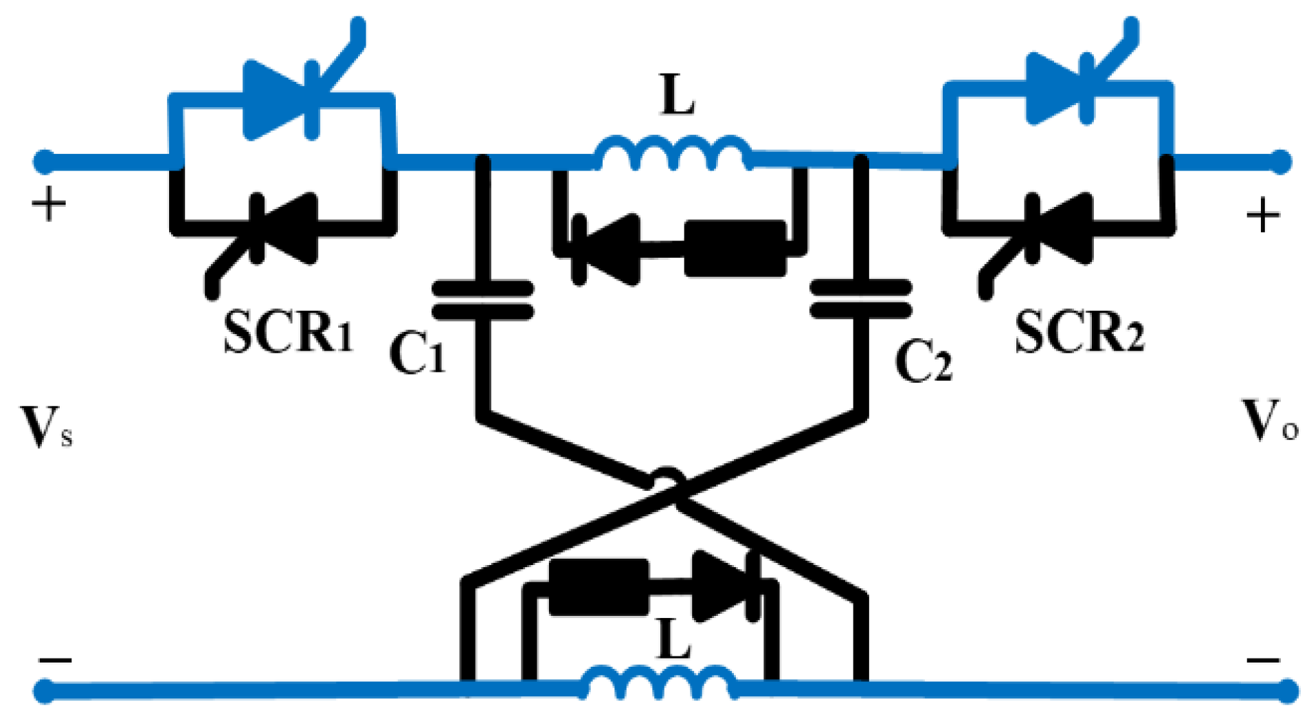
- Sun, Y.; Fan, Y.; Hou, J. Capacitor commutation type DC circuit breaker with fault character discrimination capability. J. Power Electron. 2023, 23, 1016–1027. [Google Scholar] [CrossRef]
- Yu, Z.; Yan, X.; Zhang, X.; Qu, L.; Gan, Z.; Huang, Y. The Design and Development of a Novel 10 kV/60 kA Hybrid DC Circuit Breaker Based on Mixed Solid-State Switches. IEEE Trans. Ind. Electron. 2023, 70, 2440–2449. [Google Scholar] [CrossRef]
- Qin, K.; Wang, S.; Ma, J.; Shu, J.; Zhang, R.; Liu, T. Thyristor-based DCCB with Reliable Fast Reclosing Protection Ability by Restoring Capacitor Polarity. IEEE Trans. Power Electron. 2023, 38, 7760–7770. [Google Scholar] [CrossRef]
- Kheirollahi, R.; Zhao, S.; Lu, F. Fault Current Bypass-Based LVDC Solid-State Circuit Breakers. IEEE Trans. Power Electron. 2022, 37, 7–13. [Google Scholar] [CrossRef]
- Shu, J.; Ma, J.; Wang, S.; Dong, Y.; Liu, T.; He, Z. A New Active Thyristor-Based DCCB With Reliable Opening Process. IEEE Trans. Power Electron. 2021, 36, 3617–3621. [Google Scholar] [CrossRef]
- Marwaha, M.; Satpathi, K.; Sathik, M.H.M.; Pou, J.; Gajanayake, C.J.; Gupta, A.K.; Molligoda, D.; Surapaneni, R.K. SCR-Based Bidirectional Circuit Breaker for DC System Protection with Soft Reclosing Capability. IEEE Trans. Ind. Electron. 2023, 70, 4739–4750. [Google Scholar] [CrossRef]
- Kheirollahi, R.; Zhao, S.; Zhang, H.; Lu, F. Fault Current Bypass-Based DC SSCB Using TIM-Pack Switch. IEEE Trans. Ind. Electron. 2023, 70, 4300–4304. [Google Scholar] [CrossRef]
- Kheirollahi, R.; Zhao, S.; Zhang, H.; Lu, F. Fully Soft-Switched DC Solid-State Circuit Breakers. IEEE Trans. Power Electron. 2023, 38, 6750–6754. [Google Scholar] [CrossRef]

| Description | Schneider Electric | Eaton | Siemens | ABB | LS |
|---|---|---|---|---|---|
| Model | Power PacT JDC | CJGPVS, CKDPV | HDGD | SACE Emax | Susol |
| Rated current | 30~1200 A | 150~3000 A | 50~1600 A | Up to5000 A | 16~1600 A |
| Performance voltage | 500 VDC | 600~1000 VDC | 600 VDC | 250~1000 VDC | 500–1500 VDC |
| Breaking capacity | 20 up to 50 KA | 1.5 up to 42 KA | 42 KA | 65 KA | 20 up to 50 KA |
| Ambient conditions | −10 to 60 °C | −40 to 70 °C | −25 to 70 °C | −40 to 70 °C | −25 to 55 °C |
| Operation time | ≤30 ms | 1 ms | 70–300 ms | ≤70 ms | ≤40 ms |
| Topology 1, M-DCCB [16,29] | 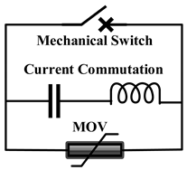 | 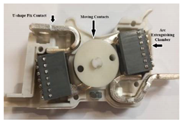 | Advantage: High breaking capacity Disadvantage: Low speed Large size Significant arc production |
| Topology 2, SS-DCCB [30,31] | 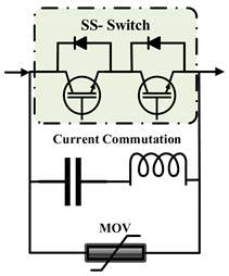 | 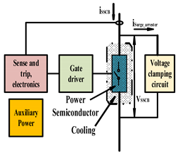 | Advantage: Very fast Small size Low loss Disadvantage: Low capacity |
| Topology 3, H-DCCB [28,32,33,34] | 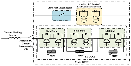 | Advantage: High breaking capacity Fast Disadvantage: Expensive | |
| Description | Topology 1 [53] | Topology 2 [54] | Topology 3 [55] |
|---|---|---|---|
| Proposed Model | 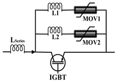 | 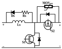 | 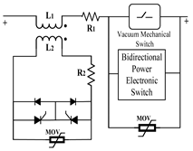 |
| Model Verification | 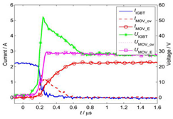 | 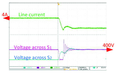 | 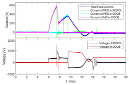 |
| Technique | Separated MOV | Ground Clamping | MC FCL |
| Technology | MOV-IGBT | MOV-MOSFET, IGBT | MOV-IGBT |
| Vdc/Idc | 30 v/2.5 A | 400 v/4 A | 500 v/380 A |
| Response Time | 0.4 µs | 50 ms | 1.8 ms |
| Number of Passive Components | 4 | 6 | 8 |
| Number of Active Components | 1 | 2 | ≥4 |
| Description | Topology 1 [58] | Topology 2 [59] | Topology 3 [60] |
|---|---|---|---|
| Proposed Model | 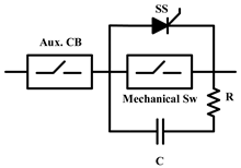 | 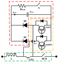 | 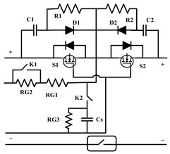 |
| Model Verification | 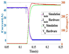 |  | 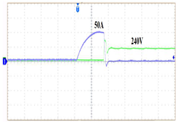 |
| Technique | A/C Circuit | VI- PMA | Soft-switched |
| Technology | Cap-IGBT | Cap-IGBT | Cap-MOSFET |
| Vdc/Idc | 283 v/43.5 A | 750 v/300 A | 240 v/50 A |
| Response Time | 15 ms | 9.6 ms | 20 ms |
| Number of Passive Components | 2 | 7 | 12 |
| Number of Active Components | 3 | 5 | 5 |
| Description | Topology 1 [72,73] | Topology 2 [74] | Topology 3 [75] |
|---|---|---|---|
| Proposed Model | 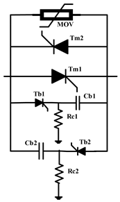 | 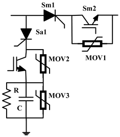 | 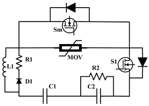 |
| Model Verification |  |  |  |
| Technique | AT CB-DCCB | TIM-Pack | LCC-AIC |
| Technology | MOV–Cap Thyristor | MOV–Cap Thyristor-IGBT | MOV–Cap SiC MOSFET |
| Vdc/Idc | 150 v/10 A | 600 v/145 A | 350 v/90 A |
| Response Time | 1.6 ms | 6 µs | 4 µs |
| Number of Passive Components | 5 | 5 | 9 |
| Number of Active Components | 4 | 4 | 2 |
Disclaimer/Publisher’s Note: The statements, opinions and data contained in all publications are solely those of the individual author(s) and contributor(s) and not of MDPI and/or the editor(s). MDPI and/or the editor(s) disclaim responsibility for any injury to people or property resulting from any ideas, methods, instructions or products referred to in the content. |
© 2023 by the authors. Licensee MDPI, Basel, Switzerland. This article is an open access article distributed under the terms and conditions of the Creative Commons Attribution (CC BY) license (https://creativecommons.org/licenses/by/4.0/).
Share and Cite
Moradian, M.; Lie, T.T.; Gunawardane, K. DC Circuit Breaker Evolution, Design, and Analysis. Energies 2023, 16, 6130. https://doi.org/10.3390/en16176130
Moradian M, Lie TT, Gunawardane K. DC Circuit Breaker Evolution, Design, and Analysis. Energies. 2023; 16(17):6130. https://doi.org/10.3390/en16176130
Chicago/Turabian StyleMoradian, Mehdi, Tek Tjing Lie, and Kosala Gunawardane. 2023. "DC Circuit Breaker Evolution, Design, and Analysis" Energies 16, no. 17: 6130. https://doi.org/10.3390/en16176130
APA StyleMoradian, M., Lie, T. T., & Gunawardane, K. (2023). DC Circuit Breaker Evolution, Design, and Analysis. Energies, 16(17), 6130. https://doi.org/10.3390/en16176130