
PEM Fuel Cell Applications in Road Transport


 ,
, 
Abstract
:1. Introduction
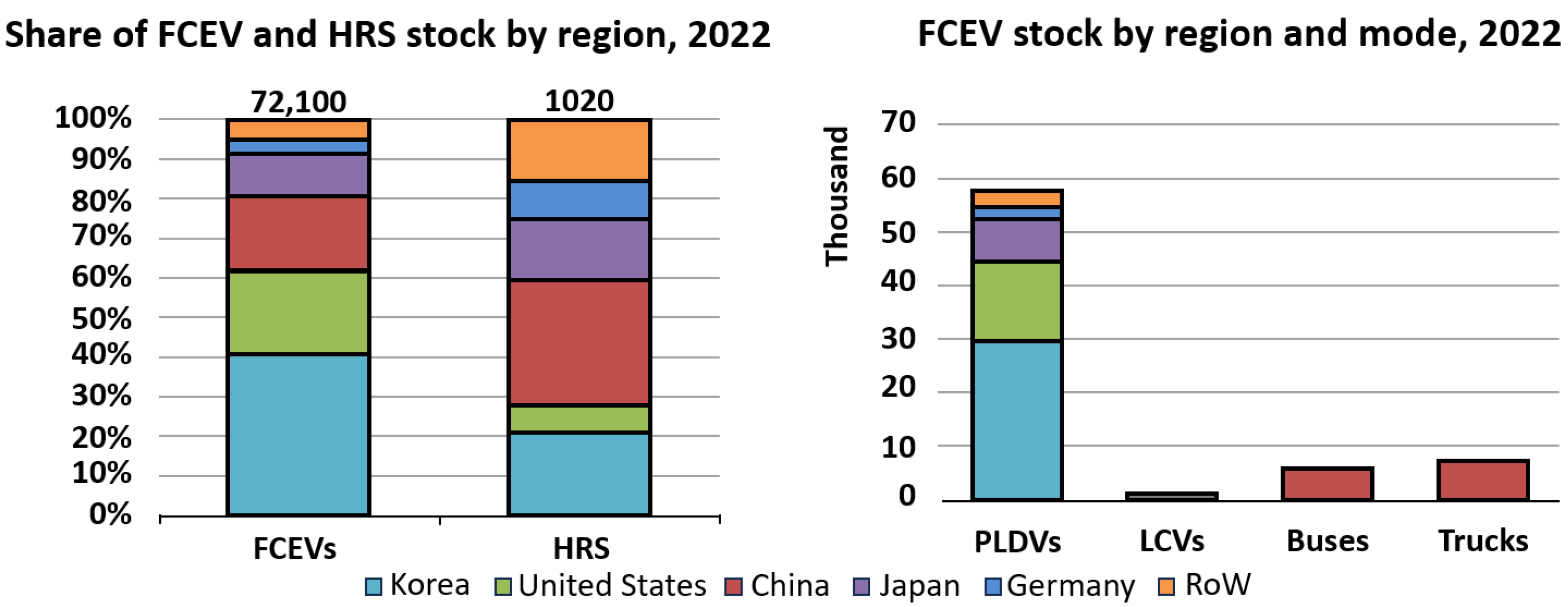
2. FCEVs Current Status
- The efficiency of a FCEV (>60%) is higher than that of ICE-powered vehicles;
- Zero emissions: water and heat are the only by-products;
- Wide range of operating power capabilities for vehicles (20 to 250 kW);
- Autonomy ranges are comparable with market references (over 400 km);
- Low refueling time (<5 min);
- No noise.
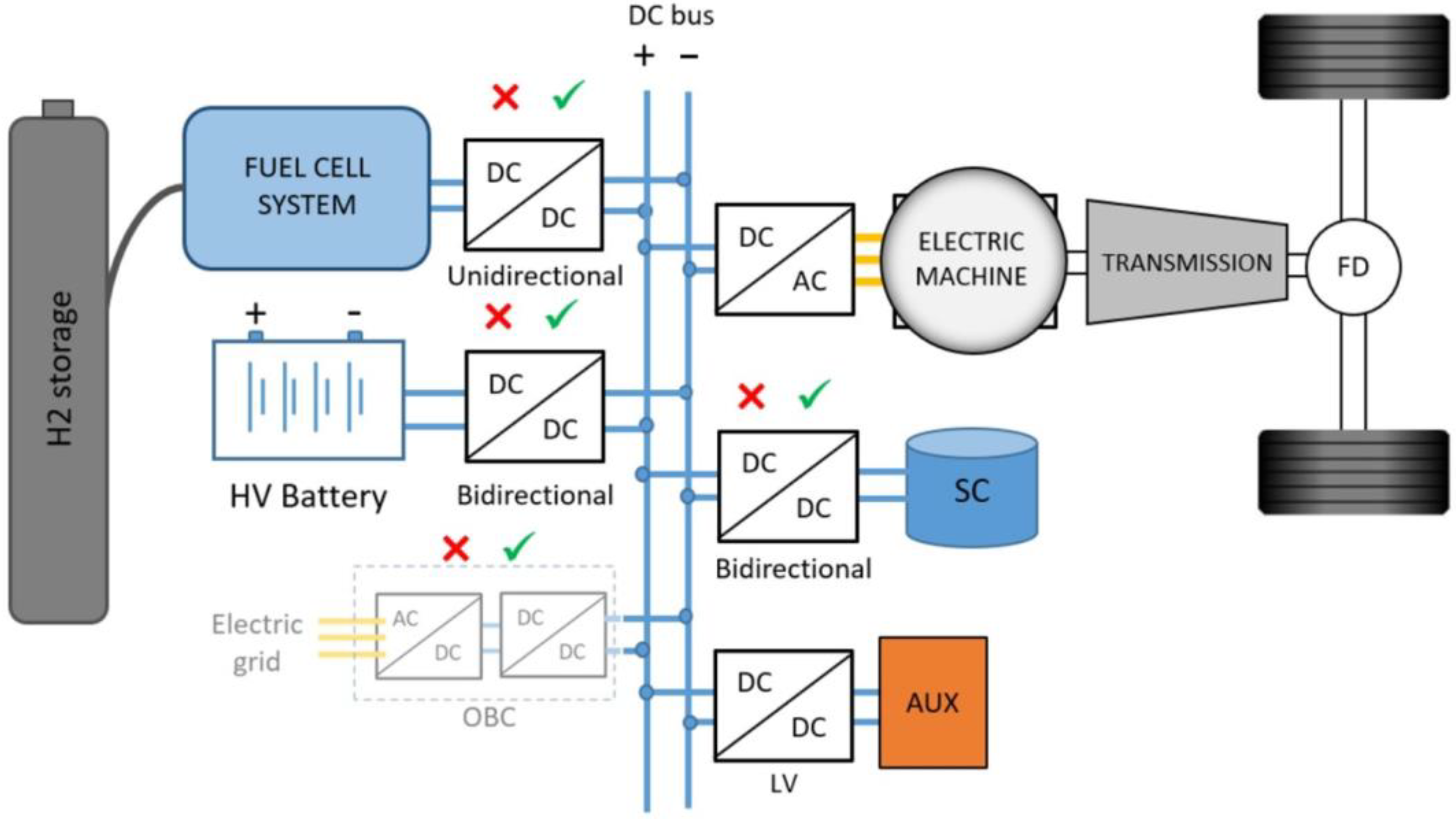
2.1. FCEVs Configuration
- Fuel cell hybrid vehicles: the drawbacks of the previous kind of vehicle could be addressed by an onboard integration of energy storage systems (batteries and/or supercapacitors) [16,31]. In this hybrid configuration, the power baseline request is guaranteed by the fuel cell, while all other energy demand (adjusting the dynamic response, peak power demand, starting off, etc.) is given by the electrical energy storage system, which can be charged and discharged based on the power demand and supply. This layout allows the fuel cell to operate at its maximum efficiency [32]. Experimental models are provided with other energy accumulators [33].
- Passive systems: the fuel cell is directly connected with the battery on the DC bus, implying that their voltages are coupled. No DC/DC converter is used after the fuel cell, and a reduction in its cost can be achieved [32];
- Active systems: typically, a DC/DC converter is used to step up the fuel cell voltage to the battery system voltage, which is usually higher. For complete control and flexibility, an additional DC/DC converter can be used in the connection of the battery to the DC link, decoupling the system operational voltage of each component [32]. Similar topologies can be developed for a supercapacitor [21]. Even if active hybrid systems are more complex in terms of control and configuration, they are much more appealing for their higher efficiency.
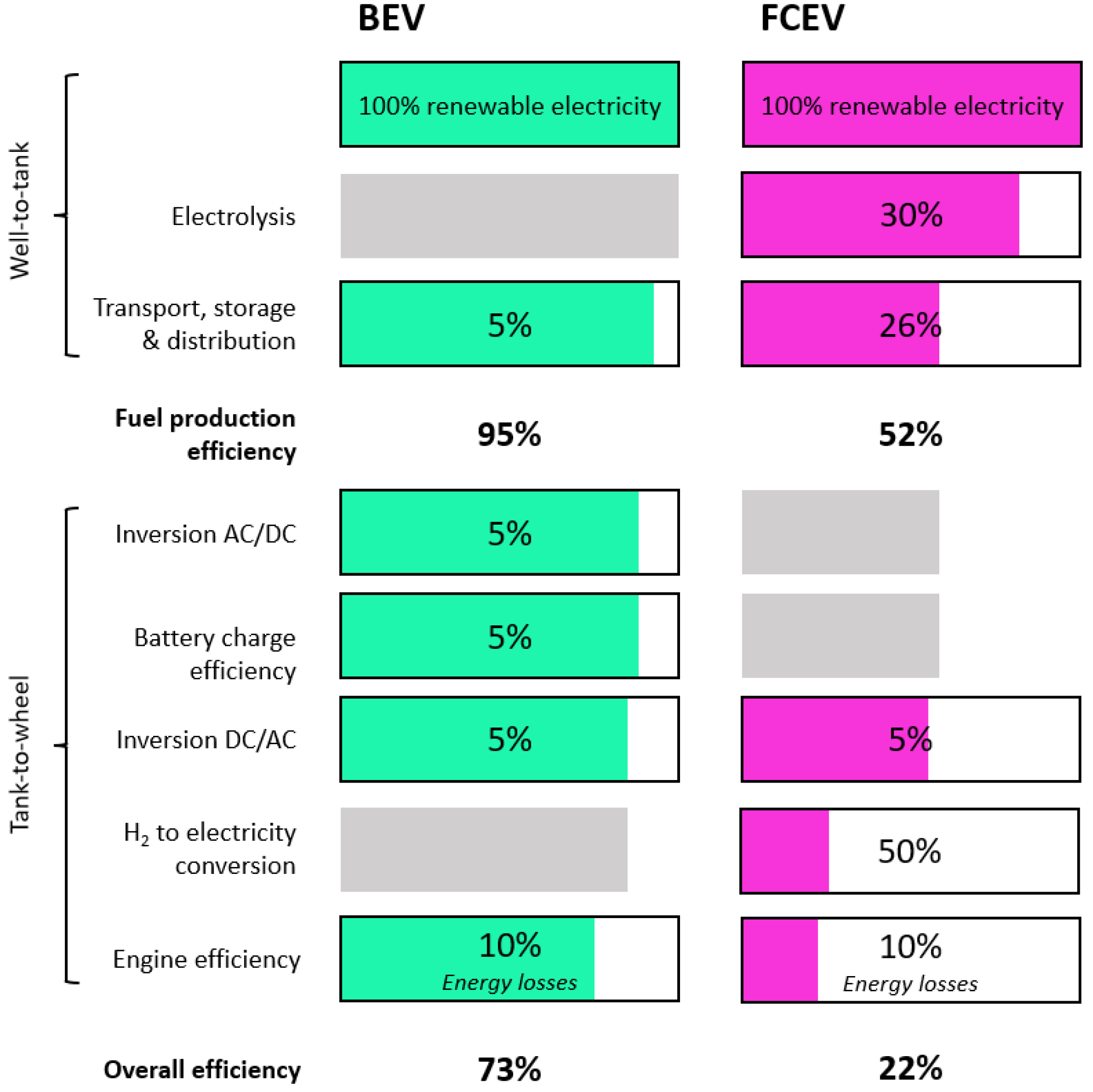
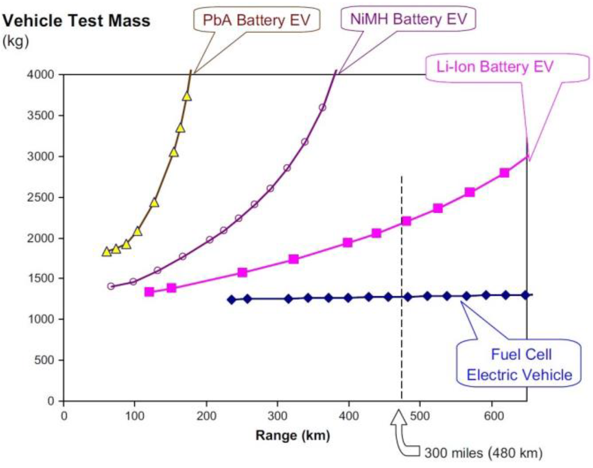
2.2. Synthetic Comparative Analysis of FCEVs and BEV Technologies

2.3. Fuel Cell Light-Duty Vehicles
2.4. Fuel Cell Heavy-Duty Vehicles
3. Proton Exchange Membrane (PEM) Fuel Cells
- A Membrane electrode assembly (MEA), composed of two electrodes separated by an electrolyte, is used for PEM fuel cells. It is a polymer membrane. The electrodes have different layers: the Catalyst Layer (CL) in direct contact with the electrolyte membrane, followed by a Microporous Layer (MPL) and a Gas Diffusion Layer (GDL), both referred to as diffusion media. Typical dimensions and materials are shown in Table 4;
- Gasket: hydrogen is a very small molecule, and the fuel cell environment is particularly harsh; therefore, specific elastomers must be used to avoid gas leakage [58];
- Bipolar plates: thanks to their geometry, they allow the different reactant gases to be fed to the specific electrode. They also have dedicated channels for heat exchange purposes. The bipolar plates enable the electrical connection of more fuel cell units for assembling a whole stack.
- ΔG is the free Gibbs energy variation (237.2 kJ/mol for the production of liquid water at 25 °C);
- is the number of electrons participating in the reaction;
- F is the Faraday constant (96,485 C/mol);
- E0 is the reversible potential of the cell.
- R is the universal gas constant [J/mol K];
- T is the temperature in [K];
- n is the number of transferred electrons;
- F is the Faraday constant [C/mol];
- pr is the partial pressure of reactants [bar];
- pp is the partial pressure of products [bar].


| Name | Thickness | Density (g/cm3) | Typical Material |
|---|---|---|---|
| Polymer electrolyte membrane (PEM) | 0.01–0.1 mm | ~2 | Nafion |
| Catalyst layer (CL) | 100 nm–0.05 mm | ~0.4 | Carbon-supported catalyst and ionomer porous composite |
| Gas diffusion layer (GDL) | 0.1–0.4 mm | 0.3–0.5 | Carbon fiber-based porous paper |
| Microporous layer (MPL) | ~0.05 mm | 0.3–0.5 | Carbon black and PTFE binder |
| Bipolar plate (BP) | 0.3–2 mm | 1.7–8 | Carbon-based composites or materials |
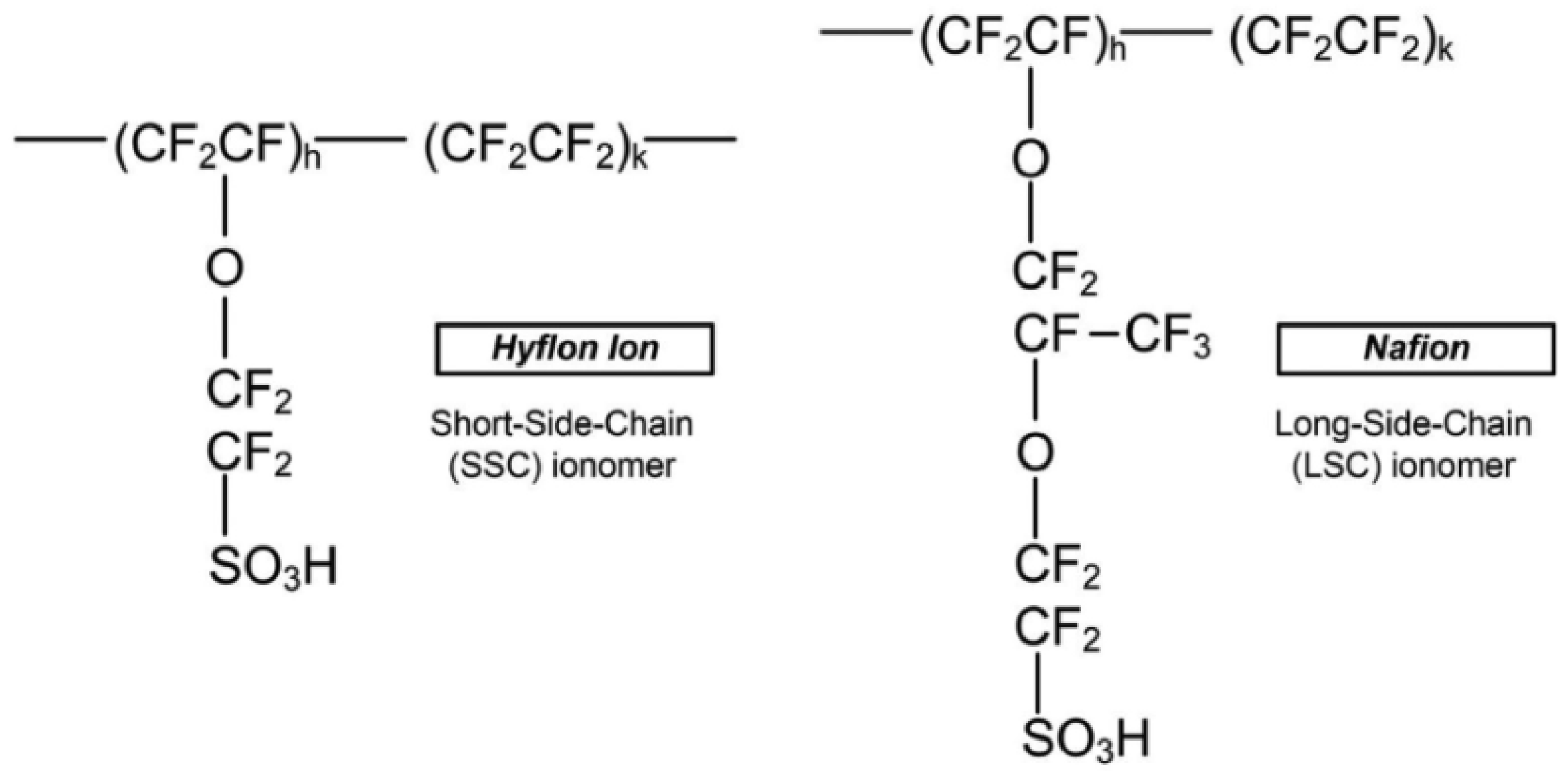
3.1. Electrolyte
- Proton conductivity is highly dependent on membrane hydration. This implies the need for accurate humidification control through different strategies (i.e., humidification of reactant gases), which increase system complexity and cost;
- Temperature limits (around 80 °C) for hydration and mechanical reasons;
- High production costs;
- Decomposition of polymer chains due to susceptibility to metallic cations;
- PEM swell/shrinking during cyclic operation, which can result in membrane failure;
- Environmentally unfriendly material;
- Possible degradation of the polymer backbone (–CF2–) for the reaction with hydrogen.
3.2. Electrodes
3.2.1. Catalyst Layer
3.2.2. Diffusion Media
3.3. Bipolar Plates
- Parallel: low pressure drops, homogenous distribution of reactants, low water removal capacity, and voltage instability:
- Interdigitated: high water removal capacity, homogenous distribution of reactants, and high pressure drops;
- Pin-type: low pressure drops, low water removal capacity, and uneven distribution of reactants;
- Spiral: low humidity requirements and high pressure drops;
- Serpentine: high water removal capacity, uneven distribution of reactants, high pressure drops.
4. BoP of Fuel Cell Systems in FCEVs
- Air supply system: Generally consisting of a compressor, a humidifier, and an air filter. This subsystem provides air to the cathode of the fuel cell;
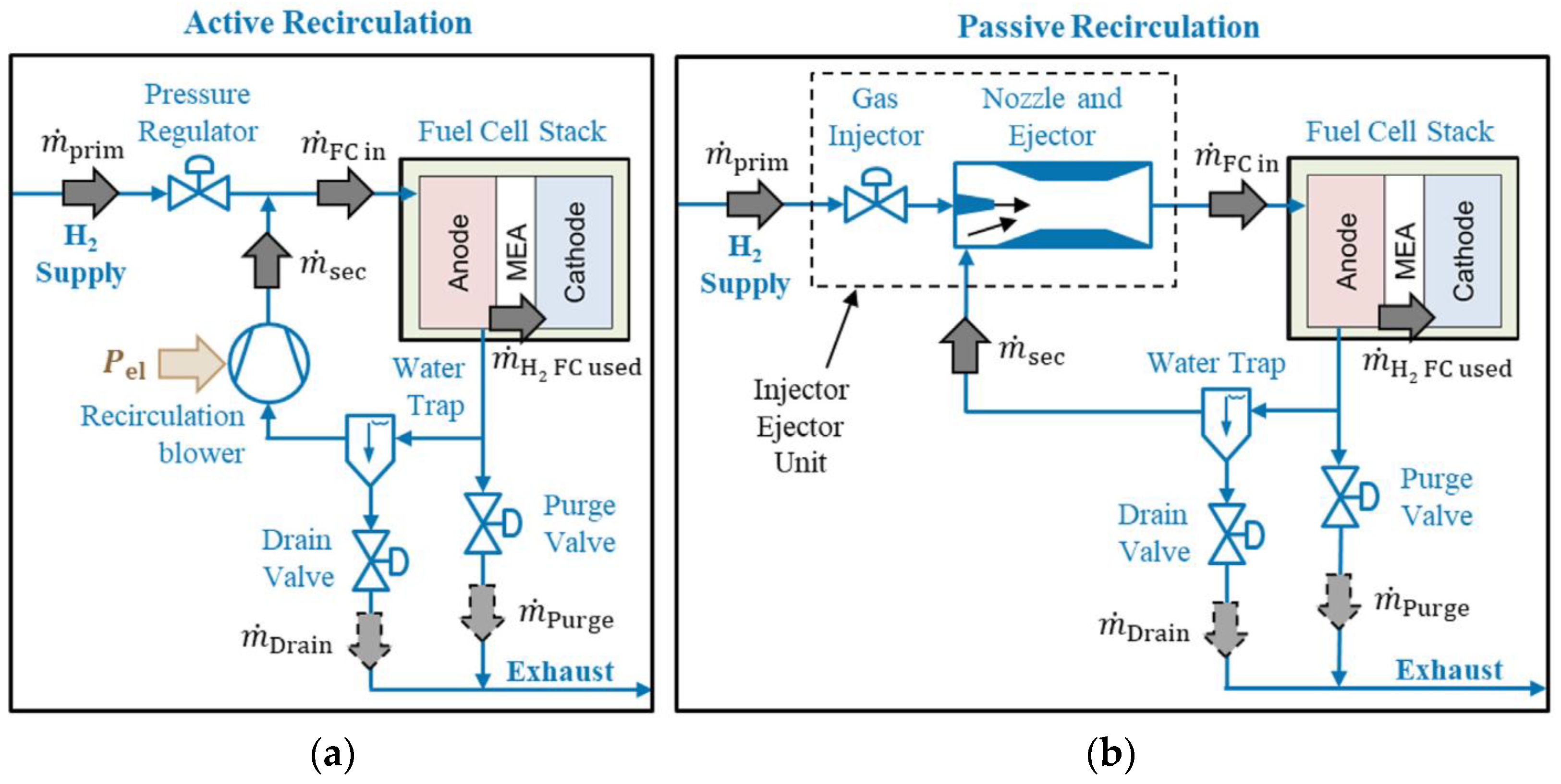
- Hydrogen supply system: Generally consisting of a tank, a pressure control valve, a recirculator, and purge valves. This subsystem provides hydrogen to the anode of the fuel cell;
- Temperature management system: Generally consisting of a pump, a thermostatic valve, a radiator, and a heater. The circuit is connected to appropriate exchange surfaces in specific channels of the cells’ bipolar plates.
4.1. Air Supply System
- According to Nernst Equation (5), pressurizing the air inlet increases the voltage and thus the power of the fuel cell. However, beyond 4 bar, the voltage increase will be smaller due to mass transport constraints;
- It reduces the stack volume;
- A higher pressure will result in a higher oxygen concentration with reduced polarization in bulk transit, thus improving the kinetics of the reaction and finally allowing a higher efficiency;
- Improved gas transport and water management, with a reduction in membrane degradation.
- ṁair [kg/s] is the air mass flow flowing through the cathode;
- I [A] is the stack current;
- n is the number of cells in the stack;
- Mair [g/mol] is the molar mass of air;
- F [C/mol] is the Faraday constant;
- xO2 is the mole fraction of oxygen in air.
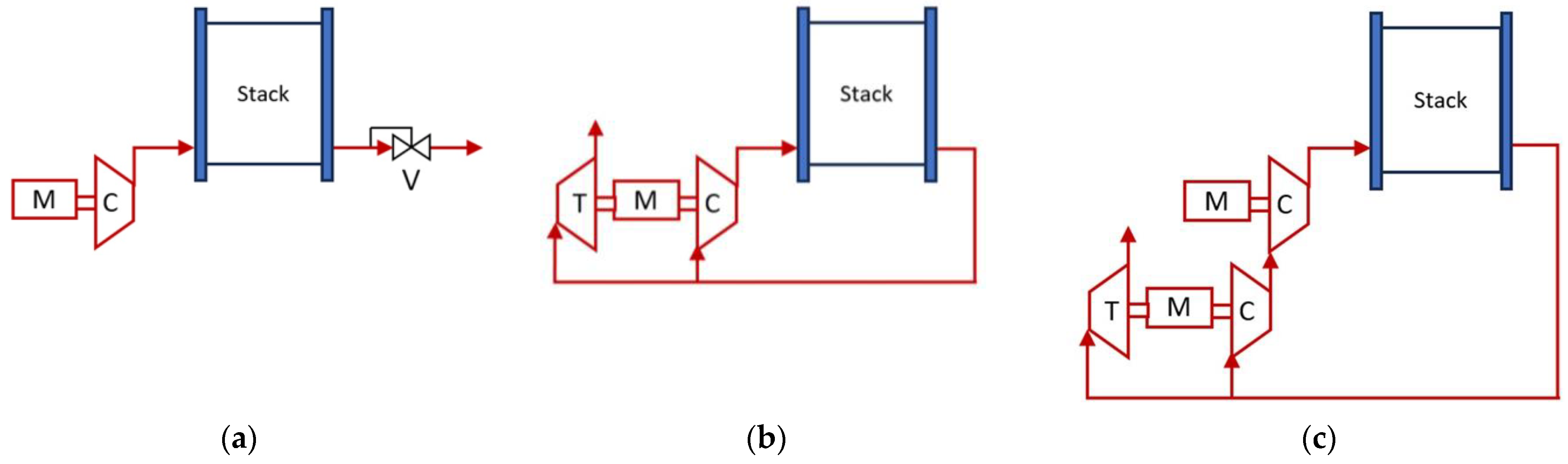
- Single stage connection: one compressor and an eventual throttle valve after the stack to control an additional increase in pressure;
- Turbocharger: one compressor and one expander (turbine). This combination can recover 20–50% of the power consumed by the compressor;
- Two-stage serial compressors: a second compressor is used to boost the compression of the first one.
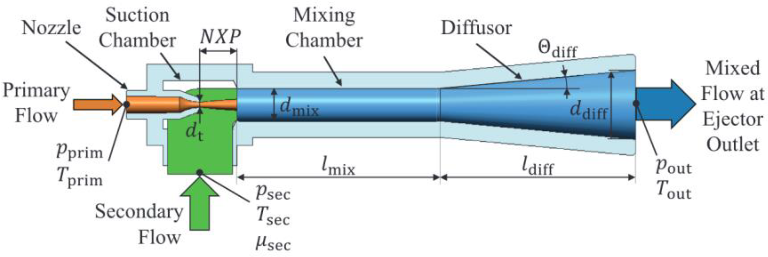
4.2. Hydrogen Supply System
- Compressed hydrogen: Generally, FCEV manufacturers implement this method to store hydrogen onboard. Pressure can vary between 350 and 700 bar according to the application and technology. To reach those values, around 15% of the lower heating value of hydrogen must be spent in the process. At those pressures, the capacity to provide a driving range similar to ICE vehicles has already been shown in Table 1, Table 2 and Table 3. Compressed hydrogen is usually contained in carbon fiber-reinforced plastic composites vessels [13,63];
- Liquid cryogenic hydrogen: To keep hydrogen in a liquid state at atmospheric pressure, a temperature of −253 °C must be reached and assured for the whole storage duration [101]. The density of liquid hydrogen is 71 kg/m3 at 1 bar and 20 K, which is much higher than the 40 kg/m3 of H2 compressed at 700 bar and 288 K [63]. Even if a high-pressure system can be avoided, this method shows different disadvantages, such as higher energy consumption (more than 30% of the heating value), boil-off losses, high costs, and limited storage time [13]. Liquid hydrogen must be contained in properly insulated vessels [63]. To achieve the desired driving range for a wide variety of light-duty vehicle models, it will be necessary to have onboard hydrogen storage capabilities ranging from 5 to 13 kg of hydrogen [102];
- Metal hydride: This method provides high storage capacities on both a gravimetric and volumetric basis. Hydrogen molecules are stored in the chemical structure of either binary hydrides, composed of a single metal, or intermetallic hydrides, containing multiple metals [103]. Common examples are Alane (aluminum hydride, AlH3), lithium borohydride (LiBH4), and sodium borohydride (NaBH4) [63]. The principal advantages of this technology consist of its compactness and a reduction in refueling costs of around 36–39% [55,103,104]. The main drawbacks of this approach are the heavy storage devices required (even though in some cases they can be used as ballast) [55], the low hydrogen release rate, the higher refueling time, and the high temperatures/pressures necessary for reversible operation [63]. However, thermal integration may be achieved: hydrogen absorption and desorption are associated with the release/absorption of large amounts of heat; hence, it is possible to use up to 40–45% of the heat produced by the fuel cell during the operation to improve the overall system efficiency [55,105,106];
- New hydrogen storage approaches are being explored using metal organic frameworks (MOFs), but they are still at an early stage of research [13].
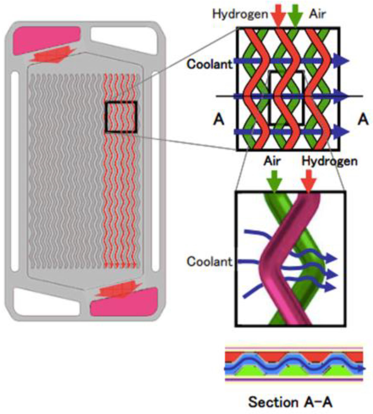
4.3. Temperature Management System
- A nearly constant temperature of about 80 °C: Membrane hydration strongly depends on saturated steam pressure, which is an exponential function of the temperature. Excessive temperature may give rise to membrane dryness, resulting in high ionic resistance, ohmic losses, and material degradation. Meanwhile, low temperatures facilitate the formation of liquid water products, with a higher risk of electrode “flooding”, oxygen starvation, and large mass concentration polarization. Furthermore, it hinders the CL’s electrochemical reaction kinetics and the membrane’s proton conductivity [112];
- Isothermal conditions over the cell area: An uneven temperature distribution in the stack may cause local water phase changes, altering the local relative humidity. However, most importantly, it causes different electrochemical reaction rates across the system. This will finally result in scarce utilization of the catalyst and the reactants, as well as the creation of hot spots, which can lower efficiency and endanger the durability of the fuel cell [113].
5. Energy Management System
- Rule-Based Strategies: This type of control is based on predefined functions, set according to the knowledge of the system, the operating conditions, and the desired performance. Its implementation is relatively simple but not very adaptable: the results are not always accurate since the driving conditions can strongly influence the different parameters of the pre-established functions;
- Optimization-based strategy: It uses specific algorithms to find the optimal operating point of the various control parameters to optimize specific objectives, taking into account pre-established constraints. For example, optimizing fuel consumption, minimizing a specific cost function, etc. These algorithms can consider different variables and constraints simultaneously, at the expense of greater computational effort. By using this strategy, real-time information can be conveniently taken into account;
- Learning Based Strategies: It makes use of databases containing historical and real-time data for different driving conditions. This data can also be integrated into a model that optimizes power flows and overall performance. The main difference between the other strategies is their ability to learn using updated datasets.
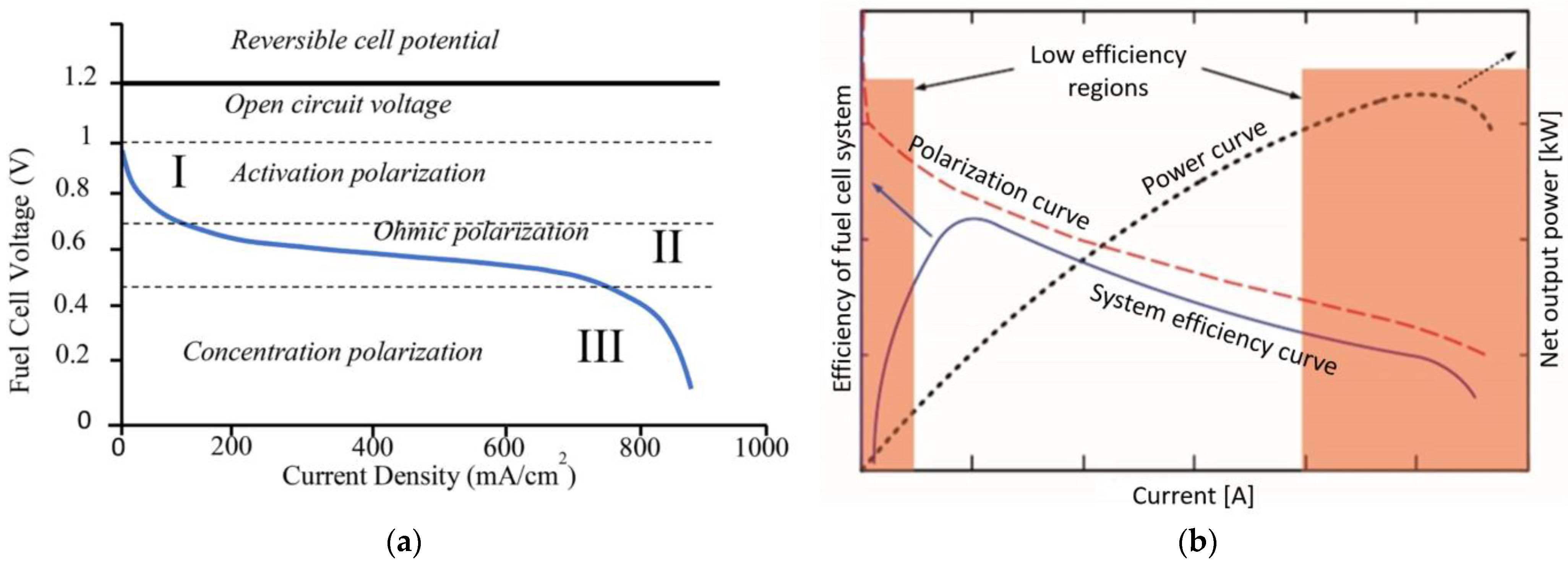
6. Stack System Efficiency
- Activation polarization: it is linked to the energy barrier that must be overcome for the redox reaction to take place. Its entity is related to the rate of electrode reactions;
- Concentration or mass transport polarization: it is due to mass transport phenomena that hinder the reactions at the electrodes (diffusion of the reactant gases through the electrodes, solution and dissolution of reactants and products inside and outside the electrolyte);
- Ohmic Polarization: it is caused by resistance to the flow of ions in the electrolyte and the flow of electrons through the electrode materials.
7. Conclusions
Author Contributions
Funding
Data Availability Statement
Conflicts of Interest
References
- Vatsalya Sohu. The Outlook for Transport: Speedy Recovery, New Uncertainties. In ITF Transport Outlook 2023; International Transport Forum, OECD: Paris, France, 2023; Chapter 1. [Google Scholar] [CrossRef]
- Global CO2 Emissions in Transport by Mode in the Sustainable Development Scenario, 2000–2070. IEA: Paris, France. 2020. Available online: https://www.iea.org/data-and-statistics/charts/global-co2-emissions-in-transport-by-mode-in-the-sustainable-development-scenario-2000-2070 (accessed on 24 July 2023).
- Ocktaeck, L. Fuel Cell Electric Vehicles. In Hybrid and Electric Vehicles–The Electric Drive Automates; Task 35; Meyer, G., Ed.; International Energy Agency: Paris, France, 2018. [Google Scholar]
- HEV TCP Annual Report 2023. Available online: https://ieahev.org/wp-content/uploads/2023/06/Digital_HEVTCP_Annual_Report_2023_v0.3-3.pdf (accessed on 24 July 2023).
- IEA. Global EV Policy Explorer. Available online: https://www.iea.org/data-and-statistics/data-tools/global-ev-policy-explorer (accessed on 26 April 2023).
- Basma, H.; Rodríguez, F. Fuel Cell Electric Tractor-Trailers: Technology Overview and Fuel Economy; Working Paper 2022-23; International Council On Clean Transportation: Washington, DC, USA, 2022. [Google Scholar]
- Council of the EU. Fit for 55 Package: Council Reaches General Approaches Relating to Emissions Reductions and Their Social Impacts. 29 June 2022. Available online: https://www.consilium.europa.eu/en/press/press-releases/2022/06/29/fit-for-55-council-reaches-general-approaches-relating-to-emissions-reductions-and-removals-and-their-social-impacts/ (accessed on 24 July 2023).
- IEA. Trends and developments in EV markets. In Global EV Outlook 2023: Catching up with Climate Ambitions; IEA: Paris, France, 2023. [Google Scholar]
- Amending Regulation (EU) 2019/1242. 2023. Available online: https://eur-lex.europa.eu/legal-content/EN/TXT/?uri=COM%3A2023%3A88%3AFIN (accessed on 24 July 2023).
- Requia, W.J.; Mohamed, M.; Higgins, C.D.; Arain, A.; Ferguson, M. How clean are electric vehicles? Evidence-based review of the effects of electric mobility on air pollutants, greenhouse gas emissions and human health. Atmos. Environ. 2018, 185, 64–77. [Google Scholar] [CrossRef]
- Zhang, H.; Sun, C.; Ge, M. Review of the Research Status of Cost-Effective Zinc–Iron Redox Flow Batteries. Batteries 2022, 8, 202. [Google Scholar] [CrossRef]
- Gils, H.C.; Gardian, H.; Schmugge, J. Interaction of hydrogen infrastructures with other sector coupling options towards a zero-emission energy system in Germany. Renew. Energy 2021, 180, 140–156. [Google Scholar] [CrossRef]
- Aminudin, M.A.; Kamarudin, S.K.; Lim, B.H.; Majilan, E.H.; Masdar, M.S.; Shaari, N. An overview: Current progress on hydrogen fuel cell vehicles. Int. J. Hydrogen Energy 2023, 48, 4371–4388. [Google Scholar] [CrossRef]
- Cullen, D.A.; Neyerlin, K.C.; Ahluwalia, R.K.; Mukundan, R.; More, K.L.; Borup, R.L.; Weber, A.Z.; Myers, D.J.; Kusoglu, A. New roads and challenges for fuel cells in heavy-duty transportation. Nat. Energy 2021, 6, 462–474. [Google Scholar] [CrossRef]
- Wang, Y.; Seo, B.; Wang, B.; Zamel, N.; Jiao, K.; Adroher, X.C. Fundamentals, materials, and machine learning of polymer electrolyte membrane fuel cell technology. Energy AI 2020, 1, 100014. [Google Scholar] [CrossRef]
- Selmi, T.; Khadhraoui, A.; Cherif, A. Fuel cell–based electric vehicles technologies and challenges. Environ. Sci. Pollut. Res. 2022, 29, 78121–78131. [Google Scholar] [CrossRef]
- Mekhilef, S.; Saidur, R.; Safari, A. Comparative study of different fuel cell technologies. Renew. Sustain. Energy Rev. 2012, 16, 981–989. [Google Scholar] [CrossRef]
- Verma, S.; Mishra, S.; Gaur, A.; Chowdhury, S.; Mohapatra, S.; Dwivedi, G.; Verma, P. A comprehensive review on energy storage in hybrid electric vehicle. J. Traffic Transp. Eng. 2021, 8, 621–637. [Google Scholar] [CrossRef]
- Das, H.S.; Tan, C.W.; Yatim, A.H.M. Fuel cell hybrid electric vehicles: A review on power conditioning units and topologies. Renew. Sustain. Energy Rev. 2017, 76, 268–291. [Google Scholar] [CrossRef]
- Samsun, R.C.; Antoni, L.; Rex, M.; Stolten, D. Deployment Status of Fuel Cells in Road Transport: Update 2021. Energy Environ. 2021, 542, 37. [Google Scholar]
- Sorlei, I.-S.; Bizon, N.; Thounthong, P.; Varlam, M.; Carcadea, E.; Culcer, M.; Iliescu, M.; Raceanu, M. Fuel Cell Electric Vehicles—A Brief Review of Current Topologies and Energy Management Strategies. Energies 2021, 14, 252. [Google Scholar] [CrossRef]
- Pollet, B.G.; Kocha, S.S.; Staffell, I. Current status of automotive fuel cells for sustainable transport. Curr. Opin. Electrochem. 2019, 16, 90–95. [Google Scholar] [CrossRef]
- Kleen, G.; Padgett, E. Durability-Adjusted Fuel Cell System Cost; U.S. Department of Energy: Washington, DC, USA, 2021. Available online: https://www.hydrogen.energy.gov/pdfs/21001-durability-adjusted-fcs-cost.pdf (accessed on 24 July 2023).
- Zhang, T.; Wang, P.; Chen, H.; Pei, P. A review of automotive proton exchange membrane fuel cell degradation under start-stop operating condition. Appl. Energy 2018, 223, 249–262. [Google Scholar] [CrossRef]
- Arrigoni, A.; Arosio, V.; Basso Peressut, A.; Latorrata, S.; Dotelli, G. Greenhouse Gas Implications of Extending the Service Life of PEM Fuel Cells for Automotive Applications: A Life Cycle Assessment. Clean Technol. 2022, 4, 132–148. [Google Scholar] [CrossRef]
- Staffell, I.; Scamman, D.; Velazquez Abad, A.; Balcombe, P.; Dodds, P.E.; Ekins, P.; Shahd, N.; Warda, K.R. The role of hydrogen and fuel cells in the global energy system. Energy Environ. Sci. 2019, 12, 463–491. [Google Scholar] [CrossRef]
- Genovese, M.; Fragiacomo, P. Hydrogen refueling station: Overview of the technological status and research enhancement. J. Energy Storage 2023, 61, 106758. [Google Scholar] [CrossRef]
- Thompson, S.T.; James, B.D.; Huya-Kouadio, J.M.; Houchins, C.; DeSantis, D.A.; Ahluwalia, R.; Wilson, A.R.; Kleen, G.; Papageorgopoulos, D. Direct hydrogen fuel cell electric vehicle cost analysis: System and high-volume manufacturing description, validation, and outlook. J. Power Source 2018, 399, 304–313. [Google Scholar] [CrossRef]
- Olabi, A.G.; Abdelkareem, M.A.; Wilberforce, T.; Alami, A.H.; Alkhalidi, A.; Hassan, M.M.; Sayed, E.T. Strength, weakness, opportunities, and threats (SWOT) analysis of fuel cells in electric vehicles. Int. J. Hydrogen Energy 2023, 48, 23185–23211. [Google Scholar] [CrossRef]
- Manoharan, Y.; Hosseini, S.E.; Butler, B.; Alzhahrani, H.; Fou, B.T., Sr.; Ashuri, T.; Krohn, J. Hydrogen Fuel Cell Vehicles; Current Status and Future Prospect. Appl. Sci. 2019, 9, 2296. [Google Scholar] [CrossRef]
- Habib, M.S.; Arefin, P.; Salam, M.A.; Ahmed, K.; Uddin, M.S.; Hossain, T.; Papri, N.; Islam, T. Proton Exchange Membrane Fuel Cell (PEMFC) Durability Factors, Challenges, and Future Perspectives: A Detailed Review. Mat. Sci. Res. India 2021, 18, 217–234. [Google Scholar] [CrossRef]
- Luca, R.; Whiteley, M.; Neville, T.; Shearing, P.R.; Brett, D.J.L. Comparative study of energy management systems for a hybrid fuel cell electric vehicle—A novel mutative fuzzy logic controller to prolong fuel cell lifetime. Int. J. Hydrogen Energy 2022, 47, 24042–24058. [Google Scholar] [CrossRef]
- Molina-Ibáñez, E.-L.; Rosales-Asensio, E.; Pérez-Molina, C.; Pérez, F.M.; Colmenar-Santos, A. Analysis on the electric vehicle with a hybrid storage system and the use of Superconducting magnetic energy storage (SMES). Energy Rep. 2021, 7, 854–873. [Google Scholar] [CrossRef]
- Pardhi, S.; Chakraborty, S.; Tran, D.-D.; El Baghdadi, M.; Wilkins, S.; Hegazy, O. A Review of Fuel Cell Powertrains for Long-Haul Heavy-Duty Vehicles: Technology, Hydrogen, Energy and Thermal Management Solutions. Energies 2022, 15, 9557. [Google Scholar] [CrossRef]
- Battery or Fuel Cell, That Is the Question, Volkswagen. 2020. Available online: https://www.volkswagen-newsroom.com/en/stories/battery-or-fuel-cell-that-is-the-question-5868 (accessed on 24 July 2023).
- Wilken, D.; Oswald, M.; Draheim, P.; Pade, C.; Brand, U.; Vogt, T. Multidimensional assessment of passenger cars: Comparison of electric vehicles with internal combustion engine vehicles. Procedia CIRP 2020, 90, 291–296. [Google Scholar] [CrossRef]
- Thangavelautham, J. Degradation in PEM Fuel Cells and Mitigation Strategies Using System Design and Control. In Proton Exchange Membrane Fuel Cell; Taner, T., Ed.; IntechOpen: London, UK, 2018; Chapter 5. [Google Scholar]
- Cano, Z.P.; Banham, D.; Ye, S.; Hintennach, A.; Lu, J.; Fowler, M.; Chen, Z. Batteries and fuel cells for emerging electric vehicle markets. Nat. Energy 2018, 3, 279–289. [Google Scholar] [CrossRef]
- Tsakiris, A. Analysis of hydrogen fuel cell and battery efficiency. In Proceedings of the World Sustainable Energy Days 2019, Young Energy Researchers Conference, Wels, Austria, 27 February 2019. [Google Scholar]
- Aghabali, I.; Bauman, J.; Kollmeyer, P.J.; Wang, Y.; Bilgin, B.; Emadi, A. 800-V Electric Vehicle Powertrains: Review and Analysis of Benefits, Challenges, and Future Trends. IEEE Trans. Transp. Electrific. 2021, 7, 927–948. [Google Scholar] [CrossRef]
- Anselma, P.G.; Belingardi, G. Fuel cell electrified propulsion systems for long-haul heavy-duty trucks: Present and future cost-oriented sizing. Appl. Energy 2022, 321, 119354. [Google Scholar] [CrossRef]
- Thomas, C.E. Fuel cell and battery electric vehicles compared. Int. J. Hydrogen Energy 2009, 34, 6005–6020. [Google Scholar] [CrossRef]
- Dirkes, S.; Leidig, J.; Fisch, P.; Pischinger, S. Prescriptive Lifetime Management for PEM fuel cell systems in transportation applications, Part I: State of the art and conceptual design. Energy Convers. Manag. 2023, 277, 116598. [Google Scholar] [CrossRef]
- Verbruggen, F.; Hoekstra, A.; Hofman, T. Evaluation of the state-of-the-art of full-electric medium and heavy-duty trucks. In Proceedings of the 2018 World Electric Vehicle Symposium and Exhibition (EVS31), Kobe, Japan, 1–3 October 2018. [Google Scholar]
- Kast, J.; Morrison, G.; Gangloff, J.J.; Vijayagopal, R.; Marcinkoski, J. Designing hydrogen fuel cell electric trucks in a diverse medium and heavy duty market. Res. Transp. Econ. 2018, 70, 139–147. [Google Scholar] [CrossRef]
- Hao, H.; Geng, Y.; Tate, J.E.; Liu, F.; Sun, X.; Mu, Z.; Xun, D.; Liu, Z.; Zhao, F. Securing Platinum-Group Metals for Transport Low-Carbon Transition. One Earth 2019, 1, 117–125. [Google Scholar] [CrossRef]
- Hao, H.; Geng, Y.; Tate, J.E.; Liu, F.; Chen, K.; Sun, X.; Liu, Z.; Zhao, F. Impact of transport electrification on critical metal sustainability with a focus on the heavy-duty segment. Nat. Commun. 2019, 10, 5398. [Google Scholar] [CrossRef]
- Liu, F.; Mauzerall, D.L.; Zhao, F.; Hao, H. Deployment of fuel cell vehicles in China: Greenhouse gas emission reductions from converting the heavy-duty truck fleet from diesel and natural gas to hydrogen. Int. J. Hydrogen Energy 2021, 46, 17982–17997. [Google Scholar] [CrossRef]
- Kane, M. Hydrogen Fuel Cell Car Sales in 2019 Improved to 7500 Globally. 2020. Available online: www.insideevs.com/news/397240/hydrogen-fuel-cell-sales-2019-7500-globally. (accessed on 24 July 2023).
- Hyundai News. Hyundai Motor Group Reveals “FCEV Vision 2030”. 2018. Available online: https://www.hyundai.news/eu/articles/press-releases/hyundai-motor-group-reveals-fcev-vision-2030.html (accessed on 24 July 2023).
- Li, M.; Bai, Y.; Zhang, C.; Song, Y.; Jiang, S.; Grouset, D.; Zhang, M. Review on the research of hydrogen storage system fast refueling in fuel cell vehicle. Int. J. Hydrogen Energy 2019, 44, 10677–10693. [Google Scholar] [CrossRef]
- Sinha, P.; Brophy, B. Life cycle assessment of renewable hydrogen for fuel cell passenger vehicles in California. Sustain. Energy Technol. Assess. 2021, 45, 101188. [Google Scholar] [CrossRef]
- Automotive News Europe. Daimler Will end Development of Fuel Cell Cars, 22 April 2020. Available online: https://europe.autonews.com/automakers/daimler-will-end-development-fuel-cell-cars (accessed on 24 July 2023).
- Fuel Cell Electric Buses Knowledge Base, Fuel Cell Electric Buses. Available online: https://www.fuelcellbuses.eu/ (accessed on 24 July 2023).
- Yartys, V.A.; Lototskyy, M.V.; Linkov, V.; Pasupathi, S.; Davids, M.W.; Tolj, I.; Radica, G.; Denys, R.V.; Eriksen, J.; Taube, K.; et al. HYDRIDE4MOBILITY: An EU HORIZON 2020 project on hydrogen powered fuel cell utility vehicles using metal hydrides in hydrogen storage and refuelling systems. Int. J. Hydrogen Energy 2021, 46, 35896–35909. [Google Scholar] [CrossRef]
- Kenworth. T680 Fuel Cell Electric Vehicle. Available online: https://www.kenworth.com/trucks/t680-fcev/ (accessed on 11 August 2023).
- Nikola Corp. TRE FCEV. All Science. No Fiction. Available online: https://www.nikolamotor.com/tre-fcev/ (accessed on 11 August 2023).
- Lin, C.-W.; Chien, C.-H.; Tan, J.; Chao, Y.-J.; Van Zee, J.W. Dynamic mechanical characteristics of five elastomeric gasket materials aged in a simulated and an accelerated PEM fuel cell environment. Int. J. Hydrogen Energy 2011, 36, 6756–6767. [Google Scholar] [CrossRef]
- Pei, P.; Wang, M.; Chen, D.; Ren, P.; Zhang, L. Key technologies for polymer electrolyte membrane fuel cell systems fueled impure hydrogen. Prog. Nat. Sci. Mater. Int. 2020, 30, 751–763. [Google Scholar] [CrossRef]
- Benmouiza, K.; Cheknane, A. Analysis of proton exchange membrane fuel cells voltage drops for different operating parameters. Int. J. Hydrogen Energy 2018, 43, 3512–3519. [Google Scholar] [CrossRef]
- Rezk, H.; Wilberforce, T.; Olabi, A.G.; Ghoniem, R.M.; Sayed, E.T.; Ali Abdelkareem, M. Optimal Parameter Identification of a PEM Fuel Cell Using Recent Optimization Algorithms. Energies 2023, 16, 5246. [Google Scholar] [CrossRef]
- Pourrahmani, H.; Siavashi, M.; Yavarinasab, A.; Matian, M.; Chitgar, N.; Wang, L.; Van herle, J. A Review on the Long-Term Performance of Proton Exchange Membrane Fuel Cells: From Degradation Modeling to the Effects of Bipolar Plates, Sealings, and Contaminants. Energies 2022, 15, 5081. [Google Scholar] [CrossRef]
- Wang, Y.; Ruiz Diaz, D.F.; Chen, K.S.; Wang, Z.; Adroher, X.C. Materials, technological status, and fundamentals of PEM fuel cells—A review. Mater. Today 2020, 32, 178–203. [Google Scholar] [CrossRef]
- Zelovich, T.; Winey, K.I.; Tuckerman, M.E. Hydronium ion diffusion in model proton exchange membranes at low hydration: Insights from ab initio molecular dynamics. J. Mater. Chem. A 2021, 9, 2448–2458. [Google Scholar] [CrossRef]
- Banerjee, S. Handbook of Specialty Fluorinated Polymers: Preparation, Properties, and Applications; Elsevier William Andrew: Waltham, MA, USA, 2015. [Google Scholar]
- Chen, P.; Fang, F.; Zhang, Z.; Zhang, W.; Wang, Y. Self-assembled graphene film to enable highly conductive and corrosion resistant aluminum bipolar plates in fuel cells. Int. J. Hydrogen Energy 2017, 42, 12593–12600. [Google Scholar] [CrossRef]
- Rosli, N.A.H.; Loh, K.S.; Wong, W.Y.; Yunus, R.M.; Lee, T.K.; Ahmad, A.; Chong, S.T. Review of Chitosan-Based Polymers as Proton Exchange Membranes and Roles of Chitosan-Supported Ionic Liquids. Int. J. Mol. Sci. 2020, 21, 632. [Google Scholar] [CrossRef]
- Chen, C.-Y.; Su, J.-H.; Ali, H.M.; Yan, W.-M.; Amani, M. Effect of channel structure on the performance of a planar membrane humidifier for proton exchange membrane fuel cell. Int. J. Heat Mass Transf. 2020, 163, 120522. [Google Scholar] [CrossRef]
- Shao, M.; Chang, Q.; Dodelet, J.-P.; Chenitz, R. Recent Advances in Electrocatalysts for Oxygen Reduction Reaction. Chem. Rev. 2016, 116, 3594–3657. [Google Scholar] [CrossRef]
- Popov, B.N.; Ho, D.; Benjamin, T. V.A.6 Development of Ultra-Low Platinum Alloy Cathode Catalysts for PEM Fuel Cells; FY 2015 Annual Progress Report; Univ. of South Carolina: Columbia, SC, USA, 2015. [Google Scholar]
- Wang, Y.; Yu, J.; Wu, J.; Wang, Z. Rapid Analysis of Platinum and Nafion Loadings Using Laser Induced Breakdown Spectroscopy. J. Electrochem. Soc. 2017, 164, F1294–F1300. [Google Scholar] [CrossRef]
- Sharma, J.; Lyu, X.; Reshetenko, T.; Polizos, G.; Livingston, K.; Li, J.; Wood, D.L.; Serov, A. Catalyst layer formulations for slot-die coating of PEM fuel cell electrodes. Int. J. Hydrogen Energy 2022, 47, 35838–35850. [Google Scholar] [CrossRef]
- Borup, R.L.; Mukundan, R.; More, K.L.; Neyerlin, K.C.; Weber, A.; Myers, D.J.; Ahluwalia, R. PEM Fuel Cell Catalyst Layer (MEA) Architectures. In Proceedings of the Electrochemical Society Conference, Seattle, WA, USA, 13 May 2018; Available online: https://www.osti.gov/biblio/1440415 (accessed on 24 July 2023).
- Borup, R.L.; More, K.L.; Myers, D.J. FC-PAD: Fuel Cell Performance and Durability Consortium Update to USCAR Analysis of Toyota Mirai Components Provided by USCAR. In Proceedings of the USCAR, Southfield, MI, USA, 11 May 2018; Available online: https://www.osti.gov/servlets/purl/1440417 (accessed on 11 August 2023).
- Jaouen, F.; Jones, D.; Coutard, N.; Artero, V.; Strasser, P.; Kucernak, A. Toward Platinum Group Metal-Free Catalysts for Hydrogen/Air Proton-Exchange Membrane Fuel Cells. Johns. Matthey Technol. Rev. 2018, 62, 231–255. [Google Scholar] [CrossRef]
- Bai, Z.; Huang, R.; Niu, L.; Zhang, Q.; Yang, L.; Zhang, J. A Facile Synthesis of Hollow Palladium/Copper Alloy Nanocubes Supported on N-Doped Graphene for Ethanol Electrooxidation Catalyst. Catalysts 2015, 5, 747–758. [Google Scholar] [CrossRef]
- Haug, A.; Zenyuk, I.; Allen, J.; Lindell, M.; Sun, F.; Abulu, J.; Yandrasits, M.; Thoma, G.; Steinbach, A.; Kurkowski, M.; et al. Novel Ionomers and Electrode Structures for Improved PEMFC Electrode Performance at Low PGM Loadings (Final Report); 3M Company: Maplewood, MN, USA, 2020. [Google Scholar] [CrossRef]
- Pintauro, P. Fuel Cell Membrane-Electrode-Assemblies with Ultra-Low Pt Nanofiber Electrodes. DOE Hydrogen and Fuel Cells Program. Annual Progress Report. 2018. Available online: https://www.hydrogen.energy.gov/pdfs/progress18/fc_pintauro_2018.pdf (accessed on 24 July 2023).
- Wu, G. Current challenge and perspective of PGM-free cathode catalysts for PEM fuel cells. Front. Energy 2017, 11, 286–298. [Google Scholar] [CrossRef]
- Banham, D.; Ye, S. Current Status and Future Development of Catalyst Materials and Catalyst Layers for Proton Exchange Membrane Fuel Cells: An Industrial Perspective. ACS Energy Lett. 2017, 2, 629–638. [Google Scholar] [CrossRef]
- Cui, R.; Mei, L.; Han, G.; Chen, J.; Zhang, G.; Quan, Y.; Gu, N.; Zhang, L.; Fang, Y.; Qian, B.; et al. Facile Synthesis of Nanoporous Pt-Y alloy with Enhanced Electrocatalytic Activity and Durability. Sci. Rep. 2017, 7, 41826. [Google Scholar] [CrossRef]
- Zhang, J.; Wang, B.; Jin, J.; Yang, S.; Li, G. A review of the microporous layer in proton exchange membrane fuel cells: Materials and structural designs based on water transport mechanism. Renew. Sustain. Energy Rev. 2022, 156, 111998. [Google Scholar] [CrossRef]
- Malekian, A.; Salari, S.; Stumper, J.; Djilali, N.; Bahrami, M. Effect of compression on pore size distribution and porosity of PEM fuel cell catalyst layers. Int. J. Hydrogen Energy 2019, 44, 23396–23405. [Google Scholar] [CrossRef]
- Alo, O.A.; Otunniyi, I.O.; Pienaar, H.; Iyuke, S.E. Materials for Bipolar Plates in Polymer Electrolyte Membrane Fuel Cell: Performance Criteria and Current Benchmarks. Procedia Manuf. 2017, 7, 395–401. [Google Scholar] [CrossRef]
- Neto, D.M.; Oliveira, M.C.; Alves, J.L.; Menezes, L.F. Numerical Study on the Formability of Metallic Bipolar Plates for Proton Exchange Membrane (PEM) Fuel Cells. Metals 2019, 9, 810. [Google Scholar] [CrossRef]
- Baumann, N.; Blankenship, A.; Dorn, M.; Cremers, C. Evaluating Current Distribution and Influence of Defect Sites for Graphitic Compound Bipolar Plate Materials. Fuel Cells 2020, 20, 40–47. [Google Scholar] [CrossRef]
- Wei, H.; Du, C. Active Disturbance Rejection-Based Performance Optimization and Control Strategy for Proton-Exchange Membrane Fuel Cell System. Electronics 2023, 12, 1393. [Google Scholar] [CrossRef]
- Sery, J.; Leduc, P. Fuel cell behavior and energy balance on board a Hyundai Nexo. Int. J. Engine Res. 2022, 23, 709–720. [Google Scholar] [CrossRef]
- Lohse-Busch, H.; Stutenberg, K.; Duoba, M.; Liu, X.; Elgowainy, A.; Wang, M.; Wallner, T.; Richard, B.; Christenson, M. Automotive fuel cell stack and system efficiency and fuel consumption based on vehicle testing on a chassis dynamometer at minus 18 °C to positive 35 °C temperatures. Int. J. Hydrogen Energy 2020, 45, 861–872. [Google Scholar] [CrossRef]
- Zhao, Y.; Liu, Y.; Liu, G.; Yang, Q.; Li, L.; Gao, Z. Air and hydrogen supply systems and equipment for PEM fuel cells: A review. Int. J. Green Energy 2022, 19, 331–348. [Google Scholar] [CrossRef]
- Martinez-Boggio, S.; Di Blasio, D.; Fletcher, T.; Burke, R.; García, A.; Monsalve-Serrano, J. Optimization of the air loop system in a hydrogen fuel cell for vehicle application. Energy Convers. Manag. 2023, 283, 116911. [Google Scholar] [CrossRef]
- Hoeflinger, J.; Hofmann, P. Air mass flow and pressure optimisation of a PEM fuel cell range extender system. Int. J. Hydrogen Energy 2020, 45, 29246–29258. [Google Scholar] [CrossRef]
- Hou, J.; Yang, M.; Ke, C.; Zhang, J. Control logics and strategies for air supply in PEM fuel cell engines. Appl. Energy 2020, 269, 115059. [Google Scholar] [CrossRef]
- Yin, X.; Wang, X.; Wang, L.; Qin, B.; Liu, H.; Jia, L.; Cai, W. Cooperative control of air and fuel feeding for PEM fuel cell with ejector-driven recirculation. Appl. Therm. Eng. 2021, 199, 117590. [Google Scholar] [CrossRef]
- Su, H.; Ye, D.; Cai, Y.; Guo, W. Air starvation of proton exchange membrane fuel cells and its beneficial effects on performance. Appl. Energy 2022, 323, 119626. [Google Scholar] [CrossRef]
- Gomez, A.; Sasmito, A.P.; Shamim, T. Investigation of the purging effect on a dead-end anode PEM fuel cell-powered vehicle during segments of a European driving cycle. Energy Convers. Manag. 2015, 106, 951–957. [Google Scholar] [CrossRef]
- Macauley, N.; Watson, M.; Lauritzen, M.; Knights, S.; Wang, G.G.; Kjeang, E. Empirical membrane lifetime model for heavy duty fuel cell systems. J. Power Source 2016, 336, 240–250. [Google Scholar] [CrossRef]
- Carcadea, E.; Ismail, M.S.; Ingham, D.B.; Patularu, L.; Schitea, D.; Marinoiu, A.; Ion-Ebrasu, D.; Mocanu, D.; Varlam, M. Effects of geometrical dimensions of flow channels of a large-active-area PEM fuel cell: A CFD study. Int. J. Hydrogen Energy 2021, 46, 13572–13582. [Google Scholar] [CrossRef]
- Zhang, Y.; Xu, S.; Lin, C. Performance improvement of fuel cell systems based on turbine design and supercharging system matching. Appl. Therm. Eng. 2020, 180, 115806. [Google Scholar] [CrossRef]
- Cruz Rojas, A.; Lopez Lopez, G.; Gomez-Aguilar, J.; Alvarado, V.; Sandoval Torres, C. Control of the Air Supply Subsystem in a PEMFC with Balance of Plant Simulation. Sustainability 2017, 9, 73. [Google Scholar] [CrossRef]
- U.S. Department of Energy, Office of Energy Efficiency and Renewable Energy. Funding Opportunity Announcement (FOA), (EERE) DE-FOA0002022. 2019. Available online: https://eere-exchange.energy.gov/Default.aspx?foaId=600decec-1f68-4c10-bda1-9ed3aadb0735 (accessed on 24 July 2023).
- Hydrogen Storage, U.S. Department of Energy—The Office of Energy Efficiency and Renewable Energy. Available online: https://www.energy.gov/eere/fuelcells/hydrogen-storage#:~:text=Onboard%20hydrogen%20storage%20capacities%20of,of%20light%2Dduty%20vehicle%20platforms (accessed on 24 July 2023).
- Davoodabadi, A.; Mahmoudi, A.; Ghasemi, H. The potential of hydrogen hydrate as a future hydrogen storage medium. iScience 2021, 24, 101907. [Google Scholar] [CrossRef] [PubMed]
- Frank, E.D.; Elgowainy, A.; Khalid, Y.S.; Peng, J.-K.; Reddi, K. Refueling-station costs for metal hydride storage tanks on board hydrogen fuel cell vehicles. Int. J. Hydrogen Energy 2019, 44, 29849–29861. [Google Scholar] [CrossRef]
- Lototskyy, M.V.; Tolj, I.; Pickering, L.; Sita, C.; Barbir, F.; Yartys, V. The use of metal hydrides in fuel cell applications. Prog. Nat. Sci. Mater. Int. 2017, 27, 3–20. [Google Scholar] [CrossRef]
- Lototskyy, M.V.; Tolj, I.; Parsons, A.; Smith, F.; Sita, C.; Linkov, V. Performance of electric forklift with low-temperature polymer exchange membrane fuel cell power module and metal hydride hydrogen storage extension tank. J. Power Source 2016, 316, 239–250. [Google Scholar] [CrossRef]
- Singer, G.; Gappmayer, G.; Macherhammer, M.; Pertl, P.; Trattner, A. A development toolchain for a pulsed injector-ejector unit for PEM fuel cell applications. Int. J. Hydrogen Energy 2022, 47, 23818–23832. [Google Scholar] [CrossRef]
- Chiche, A.; Lindbergh, G.; Stenius, I.; Lagergren, C. Design of experiment to predict the time between hydrogen purges for an air-breathing PEM fuel cell in dead-end mode in a closed environment. Int. J. Hydrogen Energy 2021, 46, 13806–13817. [Google Scholar] [CrossRef]
- James, B.; Juya-Kouadio, J.; Houchins, C. Fuel Cell Systems Analysis. DOE Hydrogen and Fuel Cells Program Review FC163. 2017. Available online: https://www.hydrogen.energy.gov/pdfs/review17//fc163_james_2017_o.pdf (accessed on 24 July 2023).
- Besagni, G.; Mereu, R.; Inzoli, F.; Chiesa, P. Application of an integrated lumped parameter-CFD approach to evaluate the ejector-driven anode recirculation in a PEM fuel cell system. Appl. Therm. Eng. 2017, 121, 628–651. [Google Scholar] [CrossRef]
- Chen, J.; Li, J.; Zhou, D.; Zhang, H.; Weng, S. Control strategy design for a SOFC-GT hybrid system equipped with anode and cathode recirculation ejectors. Appl. Therm. Eng. 2018, 132, 67–79. [Google Scholar] [CrossRef]
- Chen, Q.; Zhang, G.; Zhang, X.; Sun, C.; Jiao, K.; Wang, Y. Thermal management of polymer electrolyte membrane fuel cells: A review of cooling methods, material properties, and durability. Appl. Energy 2021, 286, 116496. [Google Scholar] [CrossRef]
- Amirfazli, A.; Asghari, S.; Sarraf, M. An investigation into the effect of manifold geometry on uniformity of temperature distribution in a PEMFC stack. Energy 2018, 145, 141–151. [Google Scholar] [CrossRef]
- Ferrara, A.; Jakubek, S.; Hametner, C. Energy management of heavy-duty fuel cell vehicles in real-world driving scenarios: Robust design of strategies to maximize the hydrogen economy and system lifetime. Energy Convers. Manag. 2021, 232, 113795. [Google Scholar] [CrossRef]
- Mogorosi, K.; Oladiran, M.T.; Rakgati, E. Mathematical Modelling and Experimental Investigation of a Low Temperature Proton Exchange Membrane Fuel Cell. EPE 2020, 12, 653–670. [Google Scholar] [CrossRef]
- Piatkowski, P.; Michalska-Pozoga, I.; Szczepanek, M. Fuel Cells in Road Vehicles. Energies 2022, 15, 8606. [Google Scholar] [CrossRef]


| Name | Launch Date | Stack Power [kW] | Fuel Economy [km/kg] (MPGe) | Tank Capacity [kg] @700 Bar (wt%) | Range [km] (EPA) |
|---|---|---|---|---|---|
| Daimler GLC FC Hybrid SUV Plug-in | 2018 | 141.6 | 120 km/kg | 4.4 | 478 + 51 (battery) |
| Honda Clarity | 2016 | 103 | 118 km/kg | 5 | 589 |
| Hyundai ix35 | 2014 | 100 | 105 km/kg | 5.64 | 594 |
| Hyundai Nexo | 2022 | 120 | 119 km/kg | 6.33 | 756 |
| Toyota Mirai | 2021 | 128 | 116 km/kg | 5.6 | 650 |
| Name | Stack Power [kW] | Battery Size [kWh] | Tank Capacity [kg] @350 Bar (wt%) | Range [km] |
|---|---|---|---|---|
| Hyundai-Xcient | 190 | 72 | 31 | 400 |
| Daimler-GenH2 | 300 | 70 | 80 liquid | 1,000 |
| DAF-VDL | 60 | 82 | 40 | 400 |
| Kenworth T680 FCEV | 310 | 200 | 58.8 | 724 |
| MAN | 100 | 120 | 34 | 400 |
| Nikola TRE | 200 | 164 | 70 | 805 |
| Scania | 90 | 56 | 33 | 500 |
| Name | Stack Power [kW] | Battery Size [kWh] | Tank Capacity [kg] @350 Bar (wt%) | Range [km] |
|---|---|---|---|---|
| ACT ZEBA | 120 | 17.4 | 40 | 204 |
| SL AFCB | 150 | 11 | 50 | 260 |
| UC Irvine AFCB | 150 | 11 | 50 | 244 |
| Businova | 30 | 132 | 28 | 190 |
| Streetdeck FCEV (double-decker) | 85 | 48 | 30 | 200–265 |
| H2. City Gold | 60 | 29–44 | 37.5 | 250 |
| Urbino 12hydrogen | 70 | 30 | 37.5 | 220 |
| Catalyst-Type | Benefit | Remaining Challenges |
|---|---|---|
| Platinum | Mature technology. | Unable to meet long-term automotive Pt loading and catalyst layer durability targets. |
| Pt alloy/de-alloy | Mature technology; | Difficult to meet the long-term automotive Pt loading target. |
| Improved performance over Pt/C; | ||
| Enhanced MEA durability. | ||
| Core-shell * | Improved mass activity over Pt alloy; | Difficult to maintain the quality of the shell; |
| Improved durability over Pt/C; | Dissolution of the core is still a concern. | |
| Highest reported ECSA. | ||
| Shape controlled nanocrystal | Significantly higher mass activity (~×15) over Pt; | Scale-up is at an early stage; |
| Chemical synthesis (vs. electrochemical) may allow for easier scale-up vs. core-shell. | Conflicting data on stability; | |
| MEA performances have not been demonstrated yet. | ||
| Nano-frame/nano-cage ** | Significantly higher mass activity (>×20) over Pt; | Scale-up is at an early stage; |
| Highly stable (improved durability over Pt/C). | Ionomer penetration into the nanocage will likely be difficult; | |
| MEA performance at high current density may be challenging. | ||
| Non-precious metal catalyst | Potentially offer the largest benefits (significant cost reduction); | Close to meeting targets for non-automotive applications but far from automotive targets; |
| Tolerant to common contaminants. | At current volumes, PGM loading is not a major concern for non-automotive applications. |
Disclaimer/Publisher’s Note: The statements, opinions and data contained in all publications are solely those of the individual author(s) and contributor(s) and not of MDPI and/or the editor(s). MDPI and/or the editor(s) disclaim responsibility for any injury to people or property resulting from any ideas, methods, instructions or products referred to in the content. |
© 2023 by the authors. Licensee MDPI, Basel, Switzerland. This article is an open access article distributed under the terms and conditions of the Creative Commons Attribution (CC BY) license (https://creativecommons.org/licenses/by/4.0/).
Share and Cite
Mancino, A.N.; Menale, C.; Vellucci, F.; Pasquali, M.; Bubbico, R. PEM Fuel Cell Applications in Road Transport. Energies 2023, 16, 6129. https://doi.org/10.3390/en16176129
Mancino AN, Menale C, Vellucci F, Pasquali M, Bubbico R. PEM Fuel Cell Applications in Road Transport. Energies. 2023; 16(17):6129. https://doi.org/10.3390/en16176129
Chicago/Turabian StyleMancino, Antonio Nicolò, Carla Menale, Francesco Vellucci, Manlio Pasquali, and Roberto Bubbico. 2023. "PEM Fuel Cell Applications in Road Transport" Energies 16, no. 17: 6129. https://doi.org/10.3390/en16176129
APA StyleMancino, A. N., Menale, C., Vellucci, F., Pasquali, M., & Bubbico, R. (2023). PEM Fuel Cell Applications in Road Transport. Energies, 16(17), 6129. https://doi.org/10.3390/en16176129