1. Introduction
With regard to the rise in global energy needs, many researchers have been focusing on renewable energy systems because of their immense benefits and potential to solve the global energy crisis [
1]. A standalone system is capable of satisfying the local demands of present-day loads of medicine, automation, etc., or of remote locations where there is no feasibility for grid interconnection [
2].
In the literature, there are several configurations available for hybrid PV–wind-based standalone AC systems. In [
3,
4], a standalone AC system with a wind-driven induction generator, PV array and inverter is proposed. The PV array is linked to a boost converter whose output is coupled with a battery bank, which is directly interfaced to an inverter. The standalone AC load is interposed between the inverter output and the wind-driven induction generator. Thereby, with the use of the duty ratio control of the boost converter, load voltage regulation is achieved in accordance with the availability of the wind and PV sources. However, the wind unit operates without any converter or direct control. In [
5], a standalone AC load system is presented with the wind source terminals of the generator directly connected to the AC load. The power extraction from the PV to AC load consists of dual conversion stages of a DC–DC converter followed by an inverter stage whose output is interfaced to the standalone AC load. A cascaded PI-SMC control is used for the boost converter interfaced between the PV array and three-phase voltage source inverter of the system to regulate the inverter DC link voltage, and to control the AC load voltage. The configuration discussed in [
6] is a standalone hybrid wind and solar system with a diesel generator and a storage battery with individual converters dedicated for each source. Further, the integrated operation of the sources with the individual conversion stages aiming for overall power balance has been illustrated. The structure elaborated in the [
7] is a standalone AC system with the energy extraction carried out with the help of a composite sliding mode controller utilized both in a DC–DC converter for a PV source and a three-phase AC–DC converter for a wind source. Thereon, the outputs of both conversions are connected to the DC link supported by the battery and this DC link is interconnected with the AC load via an inverter. The system presented in [
8] is a standalone AC system with PV–wind in addition to a biomass source unit. Thereon, individual converters are used for each source that require an individual closed-loop control scheme as well.
The aforementioned structures are related to the dedicated individual conversion system used in conjunction with the power management and control for the combined AC and DC sources. However, these architectures result in multiple conversion stages in addition to complex control. Furthermore, there are standalone AC systems as well, functioning with a single source of wind alone (AC) or solar alone (DC). They use a single-stage conversion unit only. The system in [
9] depicts an induction generator supplying a simultaneous standalone AC and DC load. The DC load is fed from the output of the diode bridge rectifier, which is connected to the terminals of the induction generator, while the AC output is supplied with the load terminals directly interconnected to the generator terminals. This implies that there is no control involved with the standalone AC and DC load power extraction. A standalone AC system consisting of a capacitor-excited induction generator that supplies AC loads via a Matrix Converter (MC) with the closed-loop control of voltage and frequency is proposed in [
10]. The configuration in [
11] highlights a PV-based standalone AC system for water pumping applications with the usage of a single-stage, three-phase voltage source inverter. The structure in [
12] discusses a PV-based standalone AC system with the use of a reduced-source single-stage conversion inverter for PMSM drives in water pumping systems. Nowadays, most of the loads based on residential and industrial applications are powered by DC supply, which contributes to the relevance of and need for DC systems [
13]. In addition, the interfacing of these loads with the renewable energy sources’ standalone DC systems can be accomplished with less complex control.
There are many systems that either use a solar-based standalone DC system [
14] or a wind power standalone DC system [
15]. Ref. [
16] presents a topology for a DC microgrid application, supplied from a wind energy conversion system using a diode bridge rectifier and a buck converter. The architecture presented in [
17] depicts a PV solar–wind–battery-based multi-port converter using a non-linear control with a wind-unit-based DC output using an extra diode rectifier stage. The configuration presented in [
18] is a four-port converter with PV, a fuel cell and a battery for standalone DC load. A standalone DC system powered by a wind source alone is presented in [
19], and a PV-based DC microgrid system with a fuel cell and a battery is presented in [
20], which illustrates the energy management scheme. The system presented in [
21] uses a dual-stage energy management scheme that uses PV–wind–tidal energy sources to power DC loads with the assistance of individual converters for each source. Additionally, an off-grid hybrid photovoltaic, wind, and battery microgrid that is suitable for use in remote residential areas was the main focus in [
22], which utilizes individual converters for each source with individual control. Further, an energy management scheme is discussed in [
23] using a PV–wind–fuel cell for EV application and, thereby, elaborates on a scheme with dedicated converters for each source. To date, the configurations mentioned for standalone DC systems have used multi-conversion units that require individual control units as well. Recently, there have been configurations that can integrate these sources in multi-port-based architectures that perform the DC–DC conversion process. Ref. [
24] discusses a PV–wind-based dual-input, single-output converter derived from a conventional DC–DC boost converter topology, with the wind unit comprising an additional rectifier unit. The architecture in [
25] discusses a single-stage multi-port converter with a PV–fuel cell for a bipolar low-voltage DC microgrid, and thereby discusses the energy management among the sources and loads. The authors in [
26] present a topology for a standalone DC system that consists of PV, wind, and hybrid energy storage, and thereby discuss power management among the sources and loads. However, an additional AC–DC conversion stage is involved in the wind source of this system.
Most of the aforementioned systems herein consist of cascaded converter structures for the individual sources. Further, this system requires the use of complex control schemes to achieve the objectives of DC load voltage regulation and necessary power regulation. In order to improve the dependability with renewable-energy-based DC systems, it is essential to use less power electronic conversion units in conjunction with the hybrid renewable energy sources [
27]. However, very few researchers have attempted single-stage multi-port structures for the hybrid sources for standalone DC systems. Therefore, coupled with the requirements of integrating the hybrid PV–wind sources to the DC system with fewer conversion stages, this paper proposes a single-stage multi-port hybrid power converter with a PV–PMSG system that can operate with concurrent DC–DC conversion and three-phase AC–DC conversion. The important aspects of the proposed converter elaborated in this paper are outlined as follows:
Integrating hybrid PV and wind sources in the proposed single-stage power converter, with the aim of concurrent energy harvesting from both sources in the standalone DC system.
A combined control framework for regulating the load voltage of the configuration as well as extracting power from both sources has been formulated. In addition, a modified sinusoidal PWM scheme with shoot-through features has been elaborated.
Depiction of power flow between hybrid sources and loads provides insights about simultaneous AC–DC conversion and DC–DC conversion processes materializing in the proposed converter.
Demonstration of proposed power converter viability with hybrid sources in the standalone system has been carried out with the performance evaluation under varying source conditions or varying loading conditions.
This paper is structured as follows:
Section 2 depicts the principle of operation of the proposed converter;
Section 3 provides details of the control architecture implemented in the proposed configuration;
Section 4 presents the PWM scheme process with regard to the proposed converter’s operation;
Section 5 elaborates the simulation and experimental results; and finally
Section 6 concludes the article.
2. Proposed System Configuration
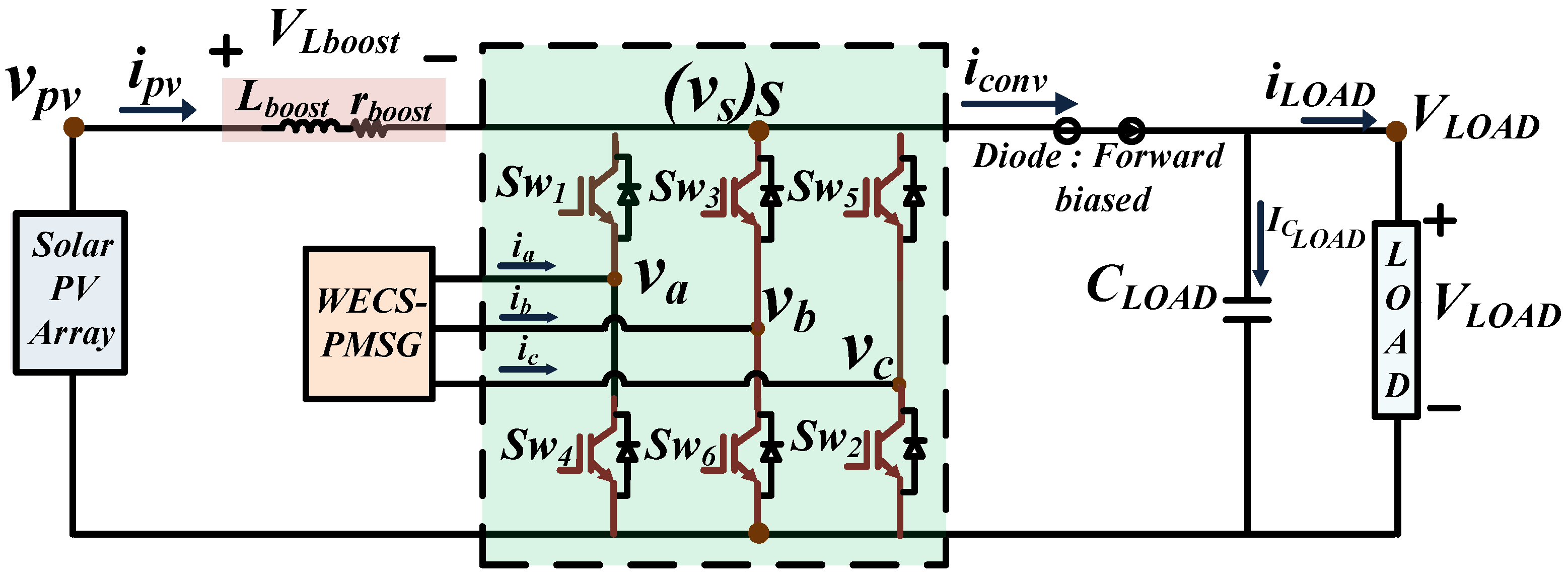
Figure 1 depicts the configuration of the proposed converter for a standalone DC system powered by combined wind–PMSG and solar energy sources. The converter is constructed using six IGBT switches
–
, two diodes
and
, two capacitors
and
, as well as four inductors
(serially connected to PV) and
(in phase with the three terminals of the PMSG).
The proposed converter is capable of performing simultaneous AC–DC and DC–DC conversions, thereby facilitating the integration of hybrid PV–wind sources into this architecture with single-stage power conversion capability. In addition, this converter can operate effectively across a wider range of irradiation levels, wind velocities, and load levels.
2.1. Principle of Operation
Considering
Figure 2, it can be noticed that when the diode
(at the load side) is in the conduction state, the voltage at node “
s”,
, will have the following relations:
where
,
and
are the switching functions of switches
,
, and
, respectively.
With regard to the relations shown in (
1), (
2), and (
3), it can be stated that the load voltage is dependent on both sources’ voltage levels, as:
Further, power demand at the load side is fulfilled by the combination of both hybrid sources power acting together as (ideally):
From relations (
4) and (
5), it can be affirmed that the hybrid sources are able to fulfil the standalone DC load requirements with the help of the proposed single-stage multi-port hybrid power converter in any scenario of source or load variations. For instance, when there is any load level variation, the load voltage level tends to be disturbed. However, the hybrid source’s voltage levels will undergo necessary variations in accordance with satisfying the relation as stated in (
4). Furthermore, in pursuit of load voltage regulation, the voltage levels of both sources vary such that power balance is achieved as stated in (
5). The sources can operate at their respective peak power values or other non-peak power values depending on the load power requirements, although the voltage level at the load side must be maintained constant.
2.2. Modes of Operation
In any scenario, the proposed converter undergoes three modes of operation—power mode, zero mode, and shoot-through mode. With regard to the conventional three-phase AC–DC rectifier that consists of power mode and zero mode only, herein, the proposed converter comprises shoot-through mode, which is part of the zero mode only. These modes are responsible for performing simultaneous AC–DC and DC–DC conversions, for wind and PV sources, respectively. These modes are elaborated as follows:
1.
Power mode: The power mode interval is denoted as the power delivered from both wind and solar to the load side. In this interval, the voltage at the switch node (
) becomes equal to the load voltage of the converter, as depicted in
Figure 3a. This mode of operation is achieved due to the conduction of diode
(at the load side). The duration of this mode is determined by both the modulation index and duty ratio.
Figure 3a shows the power interval with switches
,
, and
turned “ON”.
The flow of power from the hybrid sources to the load side occurring in the power mode of operation is represented in the form of mathematical equations, which are described below.
2.
Zero mode: The zero mode interval is depicted with either all the top switches (
,
,
) or all the bottom switches (
,
,
) of the bridge configuration being turned “ON”, as shown in
Figure 3b.
As depicted in
Figure 3b, the conducting switches are
,
, and
. During this interval, the generator current free-wheels among these bridge-leg switches while the PV-boost inductor current flows towards the load side. This implies that only the PV panel is supplying power to the load side.
Thereupon, the mathematical representations of power flow from the sources towards load side occurring in the zero mode of operation are as represented below.
Converter bridge current (
) is represented as:
Converter output capacitor current is represented as:
Converter switch node voltage is represented as:
3.
Shoot-through mode:
Figure 3c shows the circuit configuration of the proposed converter when leg “A” switches execute shoot-through mode, implying both
and
are turned “ON”. It is important to note that shoot-through mode occurs with zero mode only, as when the converter is operating in the zero mode, switching “ON” both switches on any one bridge leg can be accomplished.
Herein, as depicted in
Figure 3c, the conducting switches are
,
,
and
. During this interval, PV current flows through the shorted leg (Leg A in
Figure 3c), which acts as a charging current for the inductor
, while PMSG phase currents are free-wheeling in a similar fashion as stated in zero-mode operation.
Further, the power flow from the sources towards the load side in this shoot-through mode of operation is represented through the equations below
Converter bridge current (
) is represented as:
Converter output capacitor current is represented as:
Converter switch node voltage is represented as:
3. Control Logic Framework
The hybrid sources tend to impose different voltage levels at the load side in the proposed configuration if they are allowed to operate unregulated. Thus, to ensure that both sources together act as a single source unit and thereby tend to provide the same voltage level at the load port, it is necessary to impose a common control constraint for conducting both sources’ operation. Now, per relation (
4), it can be stated that the constant value of load voltage will tend to regulate the voltage levels of both sources and, thereby, the self-regulation will occur in the current levels from both sources accordingly. This will form the logical framework of the control architecture for the proposed converter.
The integration of hybrid sources in this single-stage architecture is with the aim of ensuring that these sources together can always fulfil the load requirements of constant load voltage and necessary load power. This implies that the sources will undergo necessary regulation in their operating points to meet the requisite of this standalone DC system. Therefore, the fundamental objective of this integrated control is to ensure the constant load voltage in the proposed system. Thereby, the load voltage error serves as an important interlink in the control logic for both sources, as shown in
Figure 4. This is instrumental in bringing together the functionality of both sources to make them operate together coherently and adaptively, thereby achieving the necessary requirements of the standalone DC system.
With regard to the PV-based DC–DC conversion control, the load voltage regulator will be utilised to generate the duty ratio control signal needed to implement the DC–DC conversion operation in the proposed converter and to regulate the PV operating voltage and current in accordance with the load requirements.
Now, in the wind–PMSG-based three-phase AC–DC conversion control, the load voltage regulator is used as an outer loop to generate the reference value for the inner current control, i.e., q- axis current (). Further, and will then be used for actuating the inner loop control in this wind–PMSG control.
Thus, this integrated control based on load voltage regulation should be able to regulate the dynamic output capabilities of hybrid sources in pursuit of achieving the overall power balance and regulating the load voltage to be constant under all operating conditions.
Potential operating scenarios of the proposed single-stage multi-port hybrid power converter under various power conditions among sources and load ports are illustrated in
Figure 5, and are stated as follows:
Scenario MPP: When the load power requirement, , is at its rated value such that it can be fulfilled by both the sources together, then the load voltage regulations in the control architecture will tend to push these hybrid sources to function at their respective peak power levels. Herein, no explicit MPP technique is involved in this control architecture; however, it is capable of achieving peak power operating points in both sources together during the rated load level demand. Therefore, the voltage levels of hybrid sources are regulated and will tend to actuate the necessary self-regulation in the current levels concurrently in both sources and, thereby, the MPP scenario can be attained in addition to the fulfilment of constant load voltage and rated load demand.
Non-MPP scenario: When the load power requirement, , is not at its rated value but at some intermediate level such that it can be fulfilled by both sources together, these hybrid sources will be functioning at some non-MPP power levels. In this scenario, the operating points of both sources will be varied in tandem to maintain a constant load voltage while simultaneously satisfying the load power.
Scenario : In this scenario, load shedding needs to be conducted. Only the critical load power demand is fulfilled by both sources together, depending on the availability of the source level.
5. Simulation, Experimental Validation and Discussion
In this paper, a single-stage multi-port hybrid power converter with PV and wind sources is proposed for a standalone DC system. Since it is able to integrate these hybrid sources into the single-stage circuitry, it is essential to investigate its viability with different operational scenarios. The system here is a standalone DC system that must always meet the load demand and keep the load voltage stable and constant. This means that both sources together should be flexible enough to meet the load demands at all times.
The attributes of the present system are given in
Table 1,
Table 2 and
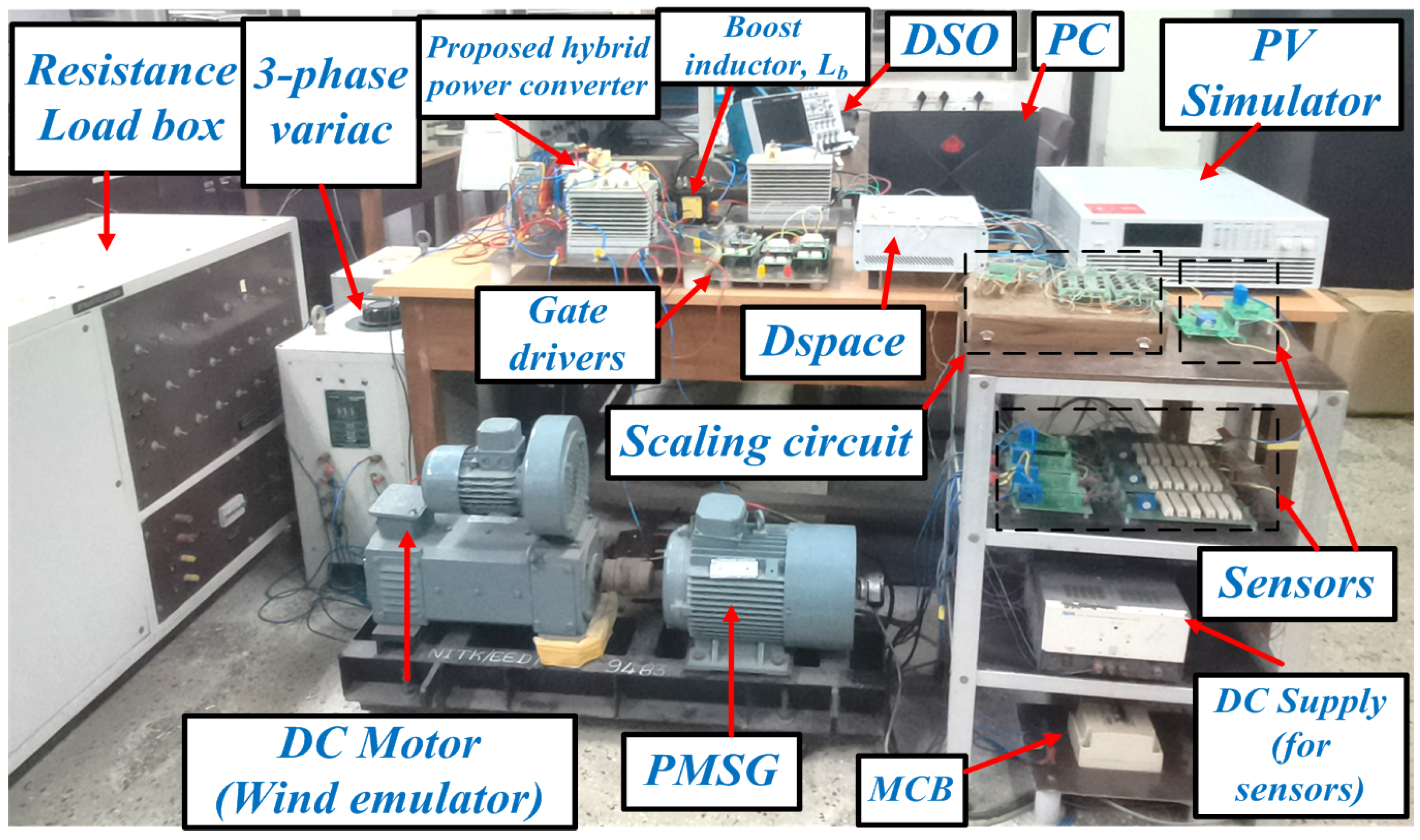
Table 3. Both the simulation and experimental investigation were conducted with the same set of parameters. The experimental set-up of the proposed system is presented in
Figure 7. The hybrid sources consisted of WECS–PMSG (Integrated Electric Co.(P) Ltd. (Bangalore, India)) and PV arrays. This WECS–PMSG was emulated with the help of a PMSG driven by a DC motor, and the PV array source was configured using a solar simulator (CHROMA 62050H-600 S). Furthermore, the proposed converter was built with semikron-made IGBT switches (SKM50GB123D) and diodes (SKKD75F12). Further, voltage sensors (LV25-P/SP2) and current sensors (LAH 25-NP) of LEM make were used.
Consequently, fundamental case studies were performed in the proposed configuration as a validation of load voltage regulation with one of the following:
- (1).
Varying load levels;
- (2).
Varying source level conditions.
The reference voltage at the load side was 750 V, which is in compliance with the standard DC voltage levels [
29].
5.1. Constant Input and Variable Load Conditions
With the constant solar irradiance level of 1 kW/m
2 and constant wind speed input (constant PMSG rotor speed of 1500 rpm), dual step changes at the load level (high–low–high) were established. The waveforms pertaining to this case study are illustrated in
Figure 8a. It can be observed that the load voltage was maintained constant at nearly the reference value of 750 V, irrespective of load level variations. However, load variations were reflected in terms of load current variations, with the load current varying from 6.1 A (high load demand) to 1 A (low load demand) and then back to 6.1 A (high load demand). In this regard, load power was 4.6 kW during the scenario of high load demand, and then it was 754 W when the load demand decreased to the low level. Therefore, it is clear from
Figure 8b,c that the sudden change in the load demand was being met simultaneously by necessary changes in both the PV and wind–PMSG sources’ operating points
Herein, it can be observed from
Figure 8b,c that the operating points for PV and PMSG were as follows:
was (391 V, 8 A) and
was (233 V, 8 A) during the high-load-demand scenario. During the low-load-demand scenario, the operating points were as follows:
= (473 V, 1 A) and
= (287 V, 2 A). Furthermore, when the load demand was increased again, the operating point of both sources was restored as follows:
was (391 V, 8 A) and
was (233 V, 8 A). The operating points of the hybrid sources were at their rated power levels, as can be noted in
Table 1 and
Table 2. Furthermore, the electromagnetic torque and rotor speed can be observed from
Figure 8d.
As the load level is changed from high load demand to low load demand, the load voltage will tend to fluctuate; thereby, to ensure constant load voltage, both sources’ voltage will increase in order to retain the load voltage level at its reference value; however, the reduction in the load current will lead to the concurrent reduction in the current injection from the PV and the PMSG. This implies that the power output from both sources will reduce with respect to its previous level to meet the overall load demand. Further, when the load demand rises, the load voltage will tend to change. However, both PV and PMSG phase voltage will decrease, maintaining the constant load voltage. Additionally, the injected PV and PMSG current will increase simultaneously following the higher load demand, thereby realising overall power balance between the source and the load sides.
5.2. Variable Input and Constant Load Conditions
In this case, the operational aspect of the converter was validated with varying input levels and constant load demand. Only a single source was varied at a time with the other source staying constant, and therefore both sources were supplying constant load demand.
CASE 1: In this condition, only irradiation levels were varied (from 1 kW/
2 to 500 W/
2 to 1 kW/
2) at constant wind speed (or constant rotor speed of 1500 rpm) and load demand. The waveforms corresponding to this condition are shown in
Figure 9. As can be seen in
Figure 9a,b, the load voltage in this case remained constant at the reference voltage (750 V) and the load current was at a constant value of 3.7 A despite the varying irradiation levels. Then, with regard to
Figure 9b,c, the wind–PMSG input delivered power in a complimentary fashion to meet the constant load requirement (2.7 kW) in response to changes in the PV power.
In this context, it can be observed that at the irradiation level of 1 kW/
2, the operating points were as follows:
wass (430 V, 4.2 A) and
was (260 V, 5 A). Then, during the 500 W/
2 irradiation scenario, the operating points were as follows:
= (420 V, 3.7 A) and
= (250 V, 6 A). Additionally, rotor speed and electromagnetic torque can be observed in
Figure 9d.
As the irradiation level decreases, the PV voltage will decrease, resulting in a dip in the PV power level followed by a dip in the PV current. This will cause the load voltage to drop from its previous voltage level; therefore, the PMSG will try to ensure that the load voltage remains the same. Because the PMSG is operating at a constant rotor speed, the PMSG terminal voltage level will tend to drop, accompanied by a rise in the PMSG current level. Overall, the PMSG power will rise to achieve a constant load voltage level and maintain overall power balance.
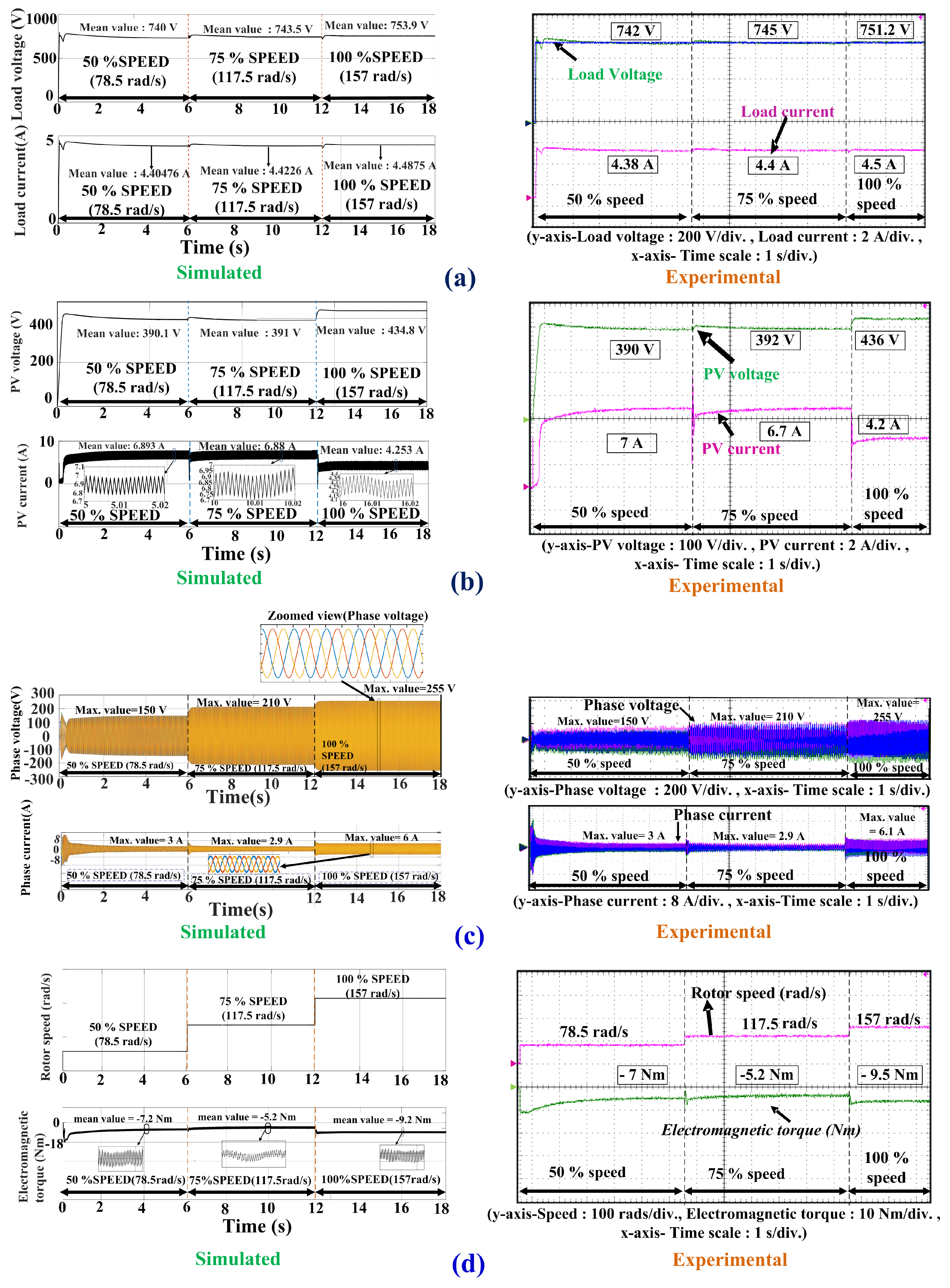
CASE 2: In this scenario, only wind source levels underwent variations (from 50% to 100% of rated speed).
Figure 10 depicts the results for the scenario of variable wind speed (or varying rotor speed) at constant irradiation level and load demand. As can be seen in
Figure 10a, the load voltage remained constant and was the same at the 750 V reference value. Furthermore, the load current remained constant at 4.4 A, and the load power held constant at 3.1 kW.
According to
Figure 10b,c, it can be ascertained that an increase in wind input power will result in a decrease in PV power in order to provide constant load power demand. Herein, it was observed that at 50% of rotor rated speed, which is 750 rpm, the operating points were as follows:
was (390 V, 7 A) and
was (150 V, 3 A). Then, at 100% of rotor rated speed, which is 1500 rpm, the operating points were as follows:
= (436 V, 4.2 A) and
= (255 V, 6.1 A). Furthermore, electromagnetic torque and rotor speed can be observed in
Figure 10d.
As rotor speed increases, the PMSG phase voltage will rise, and the PMSG power will increase with the increase of the PMSG phase currents. This will tend to increase the load voltage from the reference value. Because the load demand will stay constant and there will be an increase in the power from the PMSG source, the PV source will tend to adjust its power level to maintain the constant load power and load voltage. Therefore, despite the constant irradiation level, the PV source will try to increase its voltage level to maintain the constant load voltage; however, the PV current will decrease, and, thereby, the PV power will decrease to ensure the overall power balance in the system.


