Review

Trends and Future Perspective of Electrification in Agricultural Tractor-Implement Applications

by
Francesco Mocera
*,†,
Aurelio Somà
,
Salvatore Martelli
and
Valerio Martini
Departiment of Mechanical and Aerospace Engineering (DIMEAS), Politecnico di Torino, Corso Duca degli Abruzzi 24, 10129 Torino, Italy
*
Author to whom correspondence should be addressed.
These authors contributed equally to this work.
Energies 2023, 16(18), 6601; https://doi.org/10.3390/en16186601
Submission received: 11 August 2023 / Revised: 6 September 2023 / Accepted: 10 September 2023 / Published: 13 September 2023
(This article belongs to the Section A: Sustainable Energy)

Abstract

:
The worldwide growing demand for food is pushing the agricultural field towards new innovative solutions to increase the efficiency and productivity of cultivations. In this direction, agricultural mechanization plays a crucial role, and tractors are among the most important actors. Agricultural tractors are machines designed to push/pull special instruments usually referred to as implements, to which they may transfer power by means of a mechanical power take-off (PTO) or via hydraulic connections, thanks to the availability of pressurized oil. The tractor can be seen as a mobile power station: the more efficiently it provides power to external implements or to the ground in terms of tractive effort, the higher will be the efficiency and productivity of a certain task. However, the growing demand for greener and sustainable work machines is pushing towards new concepts of tractor powertrains with the goal of reducing, as much as possible, the amount of pollutants and GHG emissions per unit of work. In this paper, the authors will propose a review of the current trends towards electrification of agricultural tractors. Electrification can help in making vehicles more efficient and opening a new scenario for work optimization. Moreover, electrification is also involving the implements attached to the tractor and responsible for actually performing a wide variety of field tasks. However, tractor electrification requires proper attention due to the impact of high power electric systems on the vehicle configuration. For this reason, a proper level of hybridization should be considered. In this paper, a new classification method will be proposed, considering the electrification level in terms of power and as a function of the installed electric energy storage. This definition will be applied to classify the current state of the art of electric and hybrid agricultural tractors, investigating current trends in the scientific community and among industrial manufacturers with a look to the new upcoming technologies.

1. Introduction

The natural tendency of the humankind to pursue better living conditions collides with the inevitable impact on the environment we are living in. Every human activity takes resources from the environment in terms of energy or raw material and returns waste or emissions (in air and/or water), which have effects at both the global (climate change) and local (air pollution, acidification of soil and water, etc.) levels [1,2,3,4,5,6].
The agricultural field is no exception to this. Just looking at the production of greenhouse gases (GHG), agricultural activities are responsible for almost 30% of the overall CO2 production, with a possible increase following the growing demand for more food to sustain the population growth [7,8]. Automation and mechanization are crucial when it comes to optimization of farming activities. Agricultural machineries allow farmers to work on wider areas and with higher precision in order to maximize field productivity. However, results come with a price for the environment.
To withstand heavy work conditions, agricultural machineries need to be strong but, at the same time, not too expensive. For this reason, high amounts of steel and cast iron are used in their construction, increasing their environmental impact [9,10]. Considering the fuel required for agricultural machineries to work, they are responsible for up to 30% of the overall emission in agriculture [11,12]. The relevant impact of emissions from agricultural machineries required the progressive introduction of stricter and stricter regulations on pollutant emissions at the transnational level [13]. These directives limit the amount of pollutants allowed on exhaust gas emissions. Todays’ approach adopted by diesel engine OEMs has been the use of several types of filters, catalytic systems, or recirculation strategies in order to reduce the amount of pollutants on the exhaust stream [14,15]. Since the introduction of emission regulations, a consistent reduction of emissions level has been achieved. However, current exhaust after-treatment strategies cannot completely solve the problem because of side products related to each device or strategies. For this reason, new approaches should be considered to reduce the amount of GHG and pollutant emissions. The most effective way is to reduce the overall amount of fuel burnt by the agricultural machine. There are mainly three methods to achieve that:
  • Improving the overall machine efficiency, looking at higher engine efficiencies, more efficient mechanical transmissions, more intelligent and efficient way of transmitting power through hydraulics, better traction capabilities;
  • Improving the process efficiency in terms of finding the best strategies to accomplish the work and the best combination of available technologies that can help achieve the result (introducing autonomous driving to optimize field work [16,17]);
  • Introducing new alternative fuels with lower environmental impact (synthetic fuels, biofuels, etc.);
  • Adopting leading-edge solutions in terms of powertrain configurations (electric, hybrid electric, fuel-cell-powered systems) and innovative implements (electrification and/or automation).
Electrification can play an important role in tackling the above-mentioned points. The introduction of electric motors and another energy reservoir can help the engine operating at higher efficiency zones, but also allows for onboard electric energy generation to power electrified implements. Electric systems allow for a finer and more efficient controllability of actuators with respect to the traditional hydraulic (diesel powered) counterpart.
However, the electrification of off-road vehicles brings some challenges that must be faced to enhance the competitiveness of an electrified powertrain with respect to a traditional one in terms of productivity and costs. Considering pure battery electric configurations, they have the advantage of producing zero local emissions, but at the same time, they have some issues related to the limited onboard energy storage capacity. Considering the current state of art of battery technologies, battery packs have to be excessively bulky to guarantee high productivity and endurance [18]. As a consequence, to limit this drawback, huge efforts are made to improve energy storage systems [19]. Hybrid electric vehicles, which feature the presence of a downsized internal combustion engine (ICE), can overcome limits related to pure battery electric vehicles to meet the productivity requirements, but they locally produce emissions related to the presence of the thermal unit. Moreover, a deep investigation of a proper energy management strategy (EMS), which must determine how to split the power request among the electric machine and the engine, must be performed to enhance the vehicle efficiency [20]. Finally, fuel cell electric vehicles can be considered, which feature the presence of a fuel cell stack that produces electric energy from redox reactions involving, generally, hydrogen and oxygen. They have the advantage of zero local emissions and of having refueling times comparable with traditional diesel-powered vehicles; however, they require the presence of auxiliary units, such as batteries or supercaps, to fully meet the power demand, and consequently also require the development of a proper EMS. Moreover, the high cost and the thermal management of fuel cells are nowadays the main drawbacks for their application [21]. Considering the wide variety of feasible solutions for vehicle electrification, a review that presents the current research trends and efforts in the field of agricultural machineries is mandatory, in particular for investigating the most chosen paths to improve sustainability and mitigate emissions. The attention will be mainly focused on agricultural tractors due to their intrinsic nature of multipurpose machine with an additional view to implement electrification. The review will approach the available scientific literature as well as the industrial efforts in terms of prototypes. An interesting study regarding this topic was presented in [22]. However, this review introduces additional elements with respect to the existing literature, proposing a new revised definition of the hybridization factor presented in previous works [23,24]. According to the new proposed definition of the hybridization factor, the existing prototypes and the various configurations proposed in the existing literature were classified in order to highlight the present trends in terms of hybridization of the vehicle. This new approach will allow for considering the effects of the onboard energy storage in terms of both power and capacity affecting the overall improvements of the powertrain architecture. Everything will be presented considering the current limitations of these technologies, but with a look on the possibilities for further future developments. The paper is organized as follows: Section 2 illustrates the definition and main properties of traditional agricultural tractors, Section 3 introduces the topic of tractor electrification, Section 4 describes the new definition of the hybridization factor, Section 5 provides an overview of the electrification of implements, Section 6 gives a detailed survey of the control strategies in hybrid and electric vehicles, Section 7 presents the industrial cases of tractor electrification, and Section 8 summarizes the main results of the study.

2. Definitions and Characteristics of a Traditional Agricultural Tractors

Although one of the most important agricultural equipment, the multipurpose nature of a tractor and the wide range of possible configurations might generate some confusion among nonprofessionals approaching this vehicle category for the first time. In these terms, the definition proposed by the ISO 12934 standard [25] can help clarify that:
"The agricultural tractor is a self-propelled agricultural vehicle having at least two axles and wheels, endless tracks, or a combination of wheels and endless tracks, particularly designed to pull, push, carry or provide power to operate implements or pull agricultural trailers and implements, or any combination of these functions used for agricultural work (including forestry work), which may be provided with a load platform."
In other words, as shown in Figure 1, the tractor itself should be seen as a self-propelled platform in charge of pushing/pulling other devices in the field to perform specific tasks for cultivation. Usually, these devices, called implements, may require external power for mechanisms, hydraulic tools, fans, etc., to perform the work task. In this case, the tractor may supply power to the implement in several ways [26]:
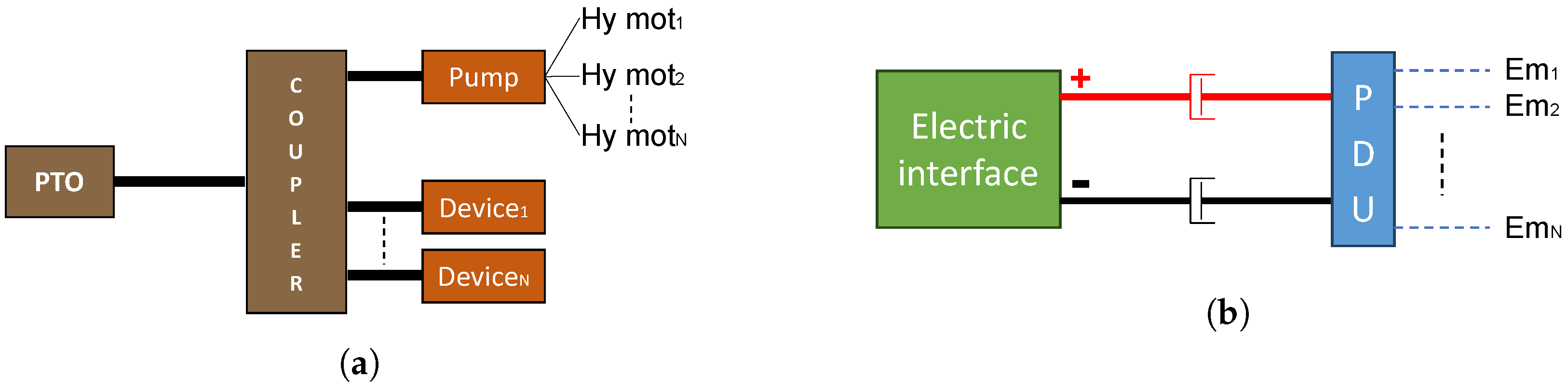
  • By means of a mechanical power take-off (PTO), which is usually connected directly to the engine output shaft or may receive power by means of a hydrostatic transmission if the tractor layout does not allow the first option;
  • Using hydraulic connections in charge of providing pressurized fluid (usually in the range of 150–205 bar) obtained from one or more pumps directly connected to the engine or to other points of the transmission depending on the tractor layout;
  • In some special cases, using connections for pressurized air in some specific implements where pneumatic actuators may require it. An additional compressor needs to be installed on the tractor side if not already present on the implement itself (in this case, it would be powered by one of the previous methods).
Figure 1. Tractor functions overview.
Energies 16 06601 g001
Recently, with the increasing level of automation and need for the monitoring of tractor/implement activities, electronic control units started to be installed also on the implement side, requiring the presence of electric power [27,28,29,30,31]. Usually, connectors with 12 V lines and, eventually, CAN BUS or ISO-BUS communication lines are used to power the implement electronic system, allowing for bidirectional communication with the tractor driver and the tractor control unit. This electric interface is not meant to transfer a high amount of power. However, as discussed in the following sections, new tractor architectures will enable high power electric connections between the tractor and the implement, opening for more advanced and optimized architectures.
The wide range of work scenarios for agricultural activiites involves very different requirements for tractors. According to the type of work the machine must carry out, it is possible to divide agricultural tractors into two major families (but with a higher number of subcategories as highlighted in [25]):
  • Open field tractors for heavy-duty tasks, such as plowing, arrowing, or transportation to be performed on very large farm areas or between farm fields far from each other.
  • Specialized tractors for specific use cases, such as orchards, vineyards, cotton fields, or gardening, where the application strongly determines the characteristics of the machines (compactness, low/high clearance, narrow wheel track, high steering capability, etc.).
Table 1 shows some relevant differences between two of the most widespread types of agricultural tractors. In general terms, the choice of the tractor characteristics should be driven by two main aspects: the need for installed power, which, according to Renius [26], could be estimated to be 3.2 kW/ha for farms smaller than 31 ha, or 1.6 kW/ha for farms bigger than 195 ha, and the need for special features, such as dimensions, ground clearance, steering capabilities, and weight strongly related to the specific cultivation. As highlighted by Beligoj et al. [32], there is also a difference in terms of use between open field and specialized tractors. For example, specialized orchard tractors are mainly used to power the attached implements required for the orchard or vineyard mechanized activities, carrying them in the field. They may also be used for some light transports using small trailers. On the other side, open field tractors mostly perform tasks where a high amount of power needs to be transferred to the wheels to have enough traction. Sometimes it may happen that the amount of power split between the implement and wheels is comparable, but in general, more power is needed on the wheel side [33]. Road transportation with trailers at full load capacity is often performed directly with the tractor itself, requiring a high amount of traction power on the wheels. These scenarios highlight a major difference between a work machine, a tractor in this case, and a road vehicle. The power coming from the main engine needs to be split and transferred to different mechanical interfaces (wheels, power take-offs, hydraulic pumps, etc.) to perform the required work tasks. As represented in Figure 2, going through all the possible power paths, the mechanical energy delivered by the engine starting from the ideal fuel content will decrease due to all the energy losses along the chain. Studies have estimated that, due to mechanical losses in the powertrain, the real power available for field work can range from 75% of the engine output mechanical power for brand-new machines down to 50% for more aged machines, and can decrease if no proper maintenance is taken into account [26]. Moreover, because of the thermal engine efficiency, no more than 40% (brand-new engine model) of the ideal diesel power content (11 kWh/L) can be converted into mechanical power at the engine output shaft.
Low engine efficiency, energy losses, and poor maintenance translate into higher fuel consumption per unit of mechanized task performed, and thus to ineffective production of pollutant emissions. Regulations on pollutant emissions have been trying to cool down the amount of emission produced by agricultural tractors [13]. To sell their vehicles on the market, manufacturers need to install engines that have demonstrated to be compliant with the emissions limits prescribed by the current regulation in force [34,35,36]. OEM engine manufacturers have approached the problem of pollutant emissions at the tailpipe, introducing aftertreatment systems (DPF, DOC), recirculating exhaust gases in the engine to lower peak temperature within the combustion chamber (EGR), or spraying solutions on the gas stream to promote chemical reactions to change the amount of specific harmful compounds (SCR) [14,15]. However, despite the great results achieved until now since their very first introduction, it seems that further improvements on pollutant emissions are requiring new aftertreatment systems, which strongly impact the vehicle side in terms of integration and power limitations [37]. For these reasons, nowadays, researchers and industry manufacturers are exploring new solutions to make the whole vehicle more efficient in performing daily tasks. In this direction, powertrain electrification is one of the most promising options because of the different possible benefits that can be introduced, such as
  • Improvements of the power transmission efficiency from the main engine to each mechanical interface;
  • More freedom for the internal combustion engine (ICE) operating point, thus the possibility for further optimization depending on the work task;
  • Finer controllability of the power delivery, thanks to advanced power electronic converters;
  • Possibility to transfer power to the attached implement through high-voltage (≥48 V) electric line.
As a consequence of the previous points and of the overloading capabilities of electric machines, it is also possible to consider engine downsizing, which further optimizes the use of the onboard fuel storage. In fact, apart from dimensional limitations, oversized diesel engines are traditionally installed on tractors to meet the most unpredictable work scenarios, but most of the time are used at partial-low loads, where their efficiency is not optimal. Thus, being able to adopt smaller and more efficient engines helped by electric machines when needed can improve the overall efficiency of the powertrain. In the following sections, a brief discussion of the most widespread electric architecture topologies is presented, highlighting their pros and cons with respect to the specific field of application considered in this work.

3. Tractor Electrification

As discussed in previous sections, a tractor is characterized by at least two main duties:
  • Delivery of traction power at the wheels;
  • Generation of power for the implement connected to at least one of the several available mechanical interfaces.
To pursue emissions reduction in nonconventional ways, a higher efficiency of the tractor/implement system is the only reasonable way to go, to be intended as the need to perform the same work tasks with lower fuel consumption. Today, modern electric power systems (electric motors, power electronics, batteries) allow for a wider range of options when it comes to power generation and delivery on tractors. Both academia and industry are exploring several electrification options for the application on a tractor powertrain:
  • Hybrid powertrains, where at least two energy sources can be controlled to achieve the best possible overall efficiency for a given work task. In this category, an ICE or fuel-cell-based systems cooperate with a battery pack (or supercapacitor bank or both of them) to satisfy the power demand.
  • Full-electric powertrains, where the work task is accomplished using the electric energy previously stored on board on a battery pack
  • Electric transmissions, where the power coming from an ICE is entirely or partially converted into electricity through a generator and then used by an electric motor connected to the transmission.
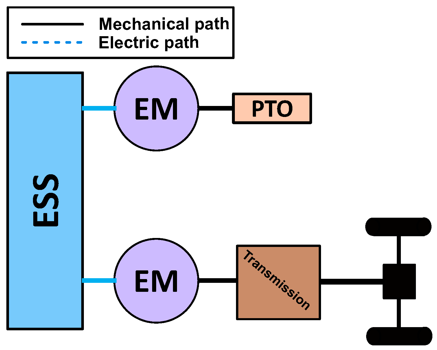
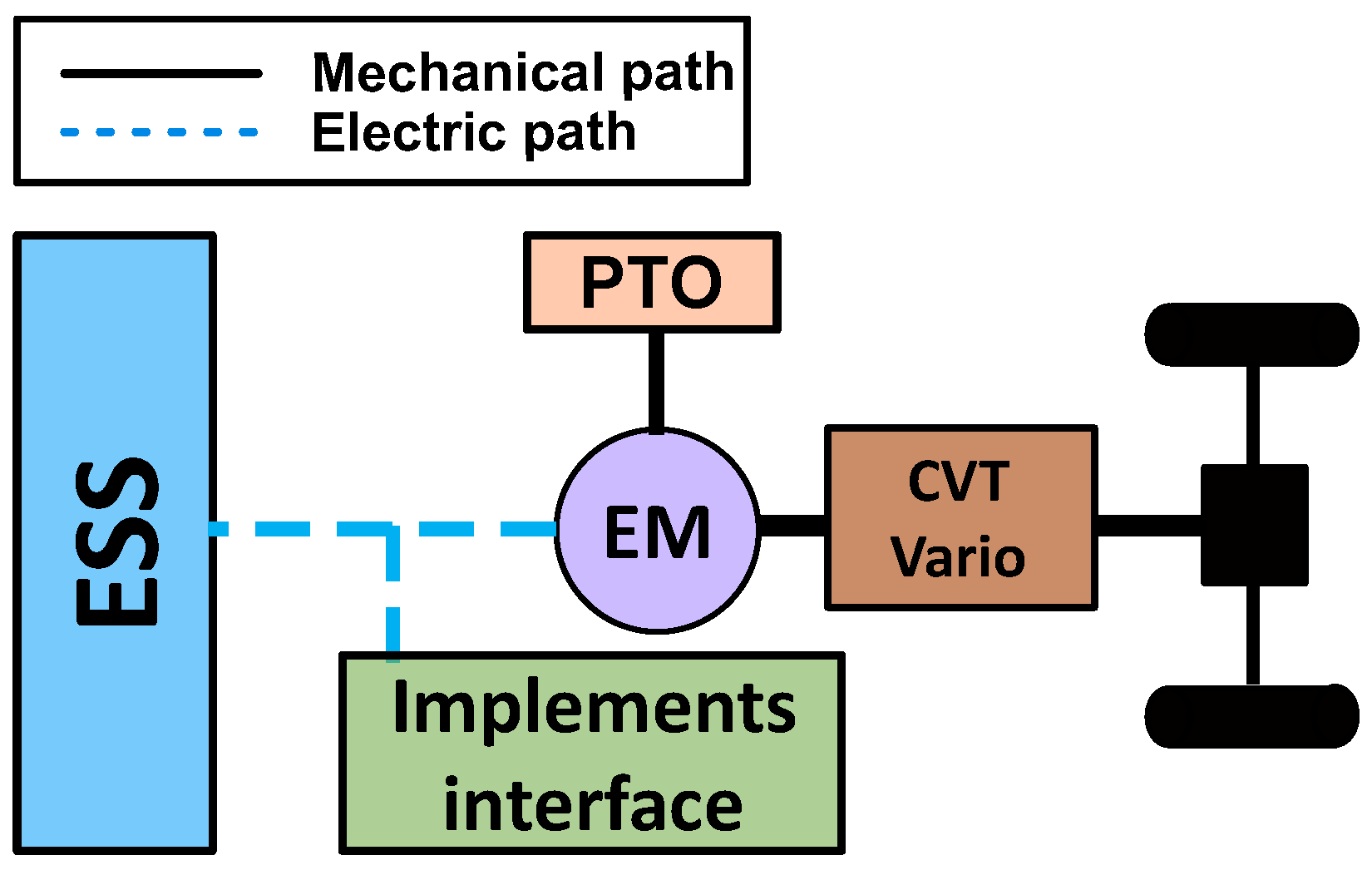
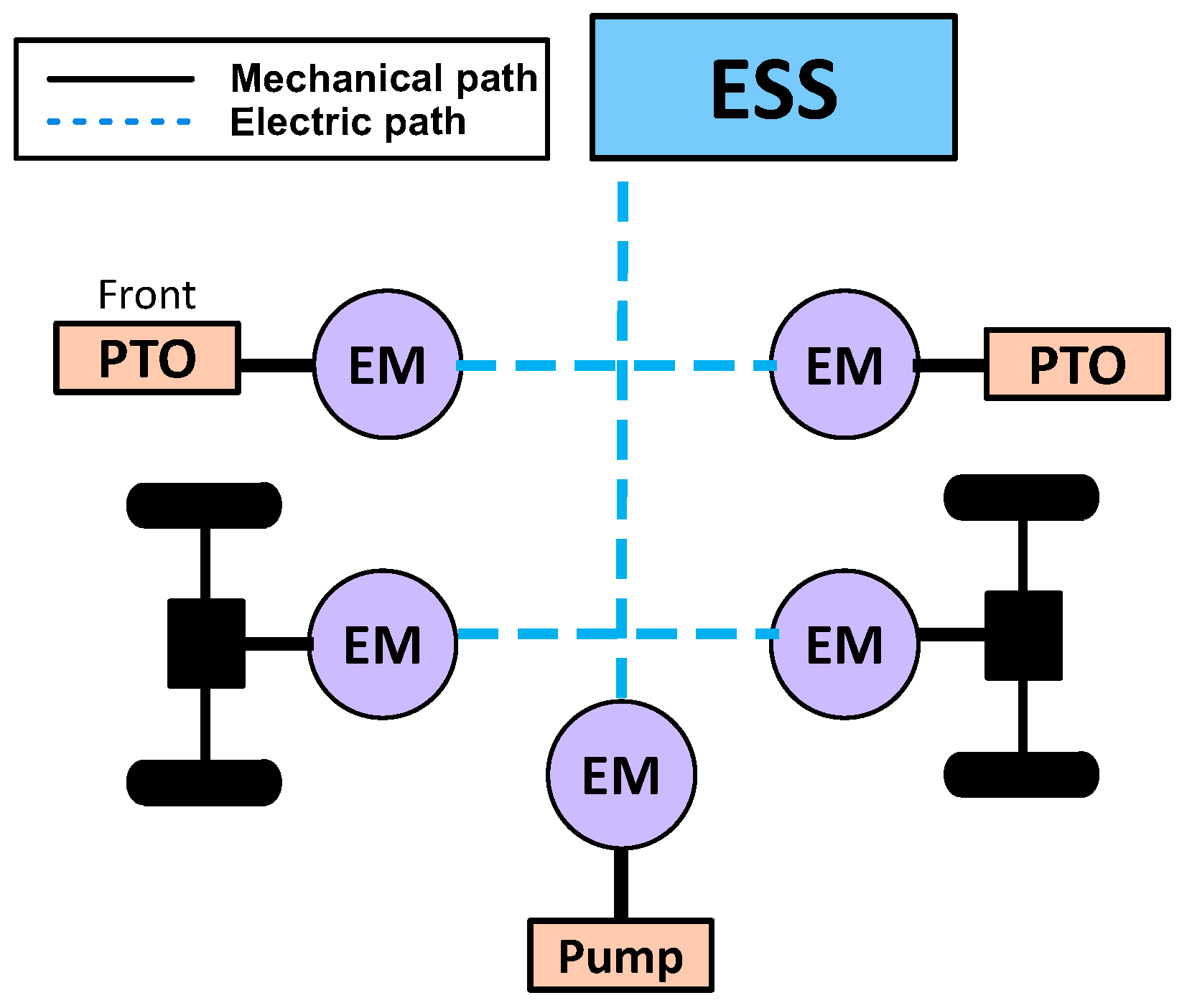
In general, the higher the level of electrification, the higher will be the chance for efficiency improvement at vehicle level, especially if the presence of an electric energy storage is considered [38,39,40]. However, going full-electric is not always the best choice if other parameters are taken into account, such as onboard integration and energy need for the work cycle [41,42,43]. For these reasons, powertrain design for a tractor requires specific attention on the type of work scenario the machine will need to face.

3.1. Full Electric

The full-electric configuration is surely the simplest option for tractor electrification. As shown in Figure 3, it may consist of one or several electric machines in charge of providing mechanical power to the different mechanical interfaces (PTO, hydraulics, electric plug, etc.). The main characteristic of this configuration is the presence of just one primary energy source, namely, the battery-based energy storage system (BESS), which should be designed and optimized with the best possible trade-off between vehicle integration and work-cycle energy demand. In the literature, hybrid energy storage systems consisting of a battery pack and arrays of supercapacitors are under investigation for the possible benefits in peak power capabilities [44]. Then power electronic converters play a key role in converting direct current (DC) into alternating current (AC) to feed each phase of the electric machine with the proper switching strategy to control both torque or speed [45,46].
Given this scenario, full-electric tractors (FETs) would be the best choice from the vehicle integration point of view, allowing also for an easy transition from traditional tractor architectures. However, two main drawbacks prevent the widespread diffusion of such configuration:
  • The lower volumetric energy density of current battery packs in comparison with diesel fuel, which would require high onboard volume to meet the energy demand of the work cycle (Li-ion battery packs have an energy density of 350 Wh/L, against 11 kWh/L for diesel);
  • The charging infrastructure, which is still not available on rural areas and probably will not have a sufficient coverage in the upcoming years.
If the first point is inherently related to the chemistry limitations of modern lithium-ion batteries, the second one is the most technical limiting factor at the moment [47]. To optimize the battery pack size, electric chargers should be used to plan charging periods during the workday. However, today the most feasible approach is to provide farmers with charging stations to be installed on their own farms. This comes with two different limitations: the tractor would always need to come back from the field to perform the programmed charge, decreasing the workday efficiency; the majority of farm chargers would be limited to 22 kW (thus excluding fast-charge protocols) due to the common power plant characteristics in standard farms. This could represent a problem, but the availability of green photovoltaic electricity installed in the farm and its low cost could represent a trade-off farmers could be willing to make [48]. Another drawback of full electric agricultural tractors is related to the heavy weight of the BESS. The high capacity required for the battery pack to meet a satisfying level of endurance may cause a noticeable increment in the overall vehicle weight due to the lower energy density of batteries compared with traditional diesel. The higher weight of the machine could be a problem in terms of soil compaction; thus, when designing the powertrain, this constraint should be taken into account.

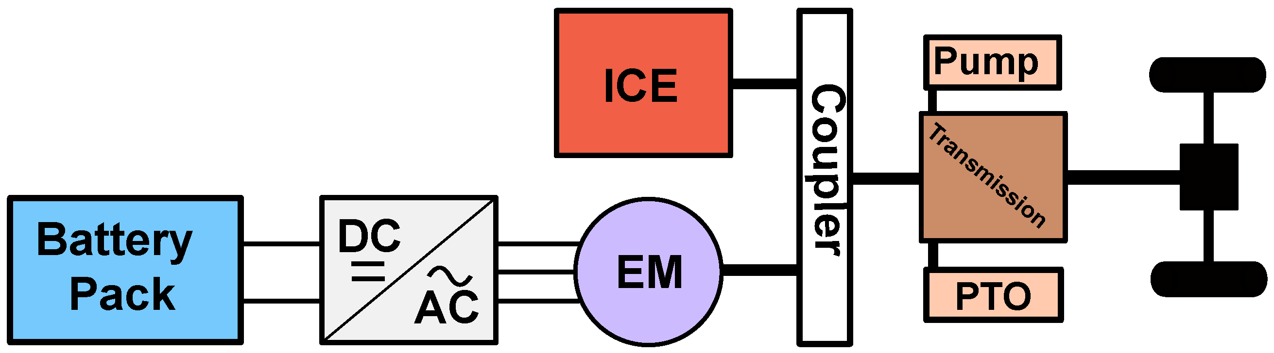
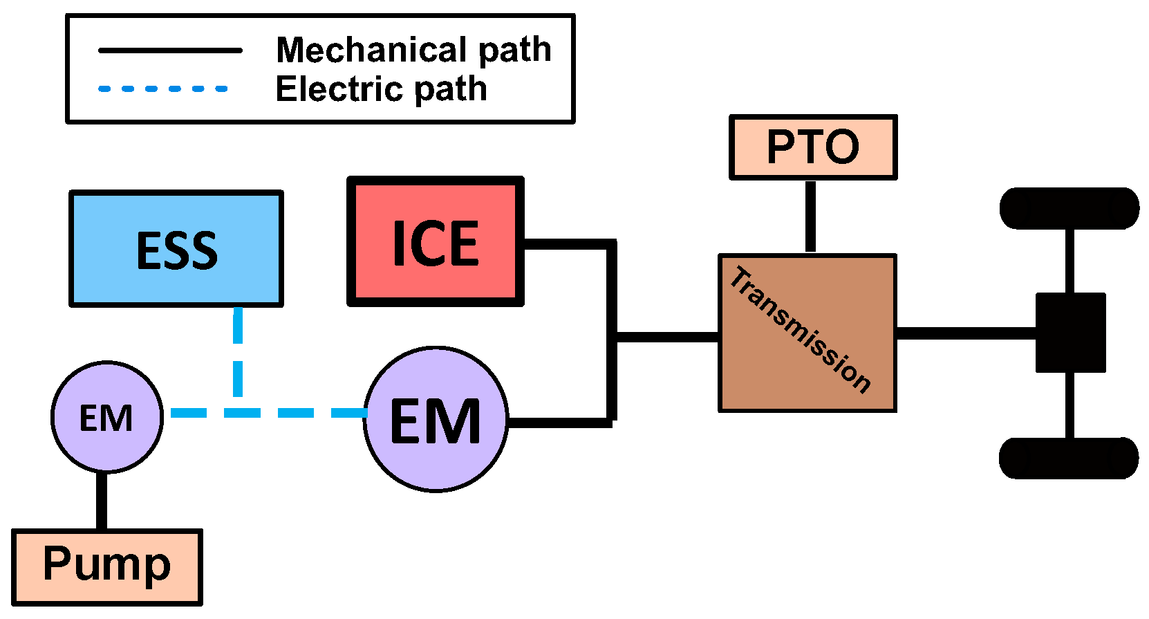
3.2. Parallel Hybrid

Hybrid powertrains are characterized by at least two energy sources cooperating together to meet the external power demand. The parallel hybrid architecture is the easiest hybrid configuration if the work cycle (in terms of energy demand) or other constraints (available onboard space) prevent the adoption of a simpler full-electric configuration. As shown in Figure 4, a parallel configuration consists of an electric machine (EM) mechanically coupled with the internal combustion engine (ICE). In this way, the electric machine can add power to the ICE output shaft or, depending on its position, to the transmission shaft or can recover energy applying a braking torque, thus generating electric power to be stored in the battery pack.
The parallel configuration in a hybrid tractor architecture [49,50,51,52] would allow for
  • Engine downsizing, covering the peaks in power demand directly with the electric system;
  • Optimization of the ICE use, in terms of work point for a given rotational speed or help in transient conditions;
  • Reasonable integration into existing tractor architecture due to the relatively low amount of components involved.
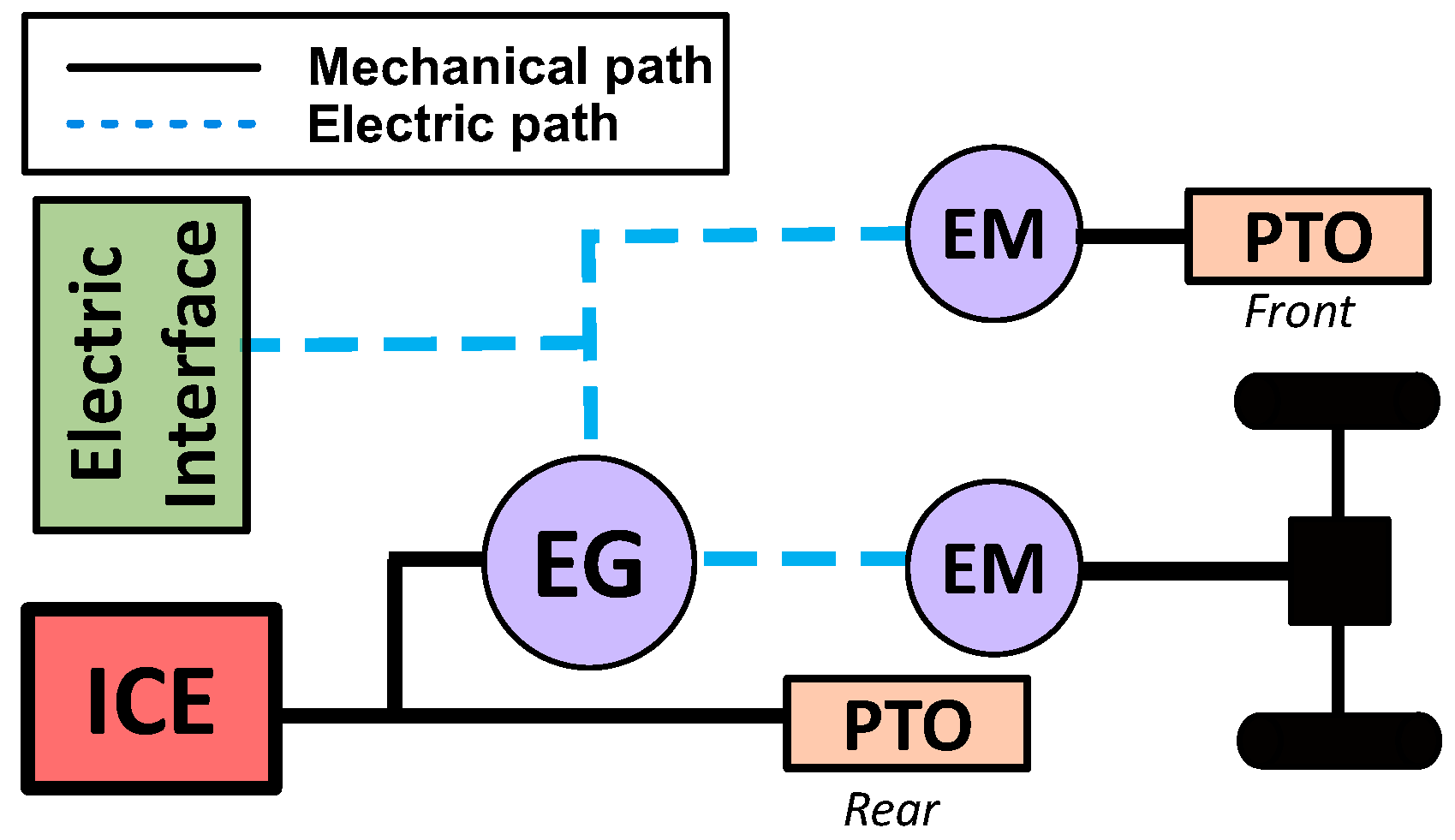
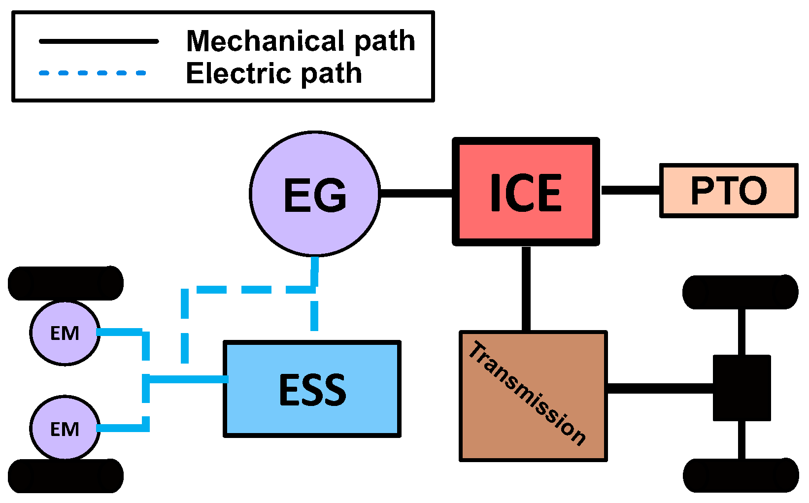
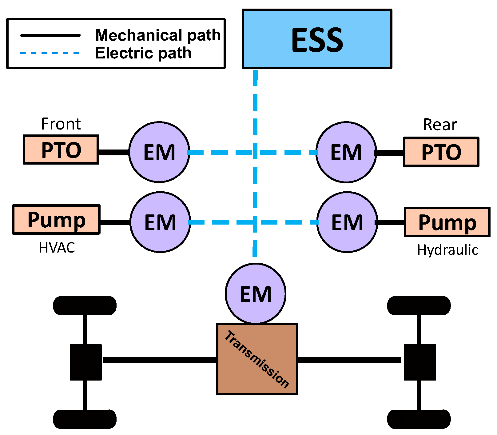
The major drawback of such configuration consists in its mechanical coupling with the ICE. Despite the great flexibility of the electric machine in adapting to the applied workload, the mechanical connection between the ICE and the rest of the transmission is still present, implying that the ICE rotational speed can never be decoupled from the rotational need of the mechanical interface, which needs power (wheels, PTO, hydraulic pumps, etc.). Mocera et al. explored an alternative solution in [53], where the parallel combination of the EM and ICE powered a hydrostatic transmission connected to the gearbox. Energy losses increased due to the hydraulic power transmission, but performance showed good results in comparison with the traditional vehicle. This parallel configuration allowed for decoupling the wheel motion from the ICE rotational speed, opening for further optimization of the thermal machine that could be investigated in future works. On the PTO shaft, the system would be a traditional parallel configuration. This is not a real concern since the PTO operating speed needs to be constant, and the gear ratios are studied to let the engine operate at its most efficient rotational speed for fuel economy or at maximum speed for maximum power.

3.3. Series Hybrid

Today’s tractors are characterized by complex gearboxes to give the operators the wider possible range of working speeds. This happens because the rotational speed of the ICE must be properly adapted to the needs of each field task to be performed [26,54,55,56]. However, the mechanical link between the ICE and the wheels prevents the best optimization of the engine operating point [57,58]. Moreover, standard tractors have also the PTO connected to the ICE, adding more and more constraints to the possible operating points, having to satisfy both work vehicle speed and PTO speed for the attached implement. To meet this need, manufacturers have recently implemented hydrostatic transmission within the driveline to decouple the vehicle speed from the engine and PTO speed [59,60] but at the cost of lower overall efficiencies. Moreover, due to the increase in power losses, also thermal management requires higher attention with the need for dedicated radiators. Electrification opens to a new way for achieving higher ICE optimization. The series hybrid architecture shown in Figure 5 allows for ICE decoupling from the mechanical interfaces.
The architecture consists of
  • An electric machine with the main role of generating electric energy from the electromechanical conversion of the power coming from the ICE;
  • One or several electric machines acting as motors for the mechanical interfaces requiring power during field work;
  • An energy storage system acting as energy buffer for the electric machines asked to cover peaks in power demand.
In principle, the ESS is not strictly required if the electric generator is finely controlled, but the lower dynamic response of the ICE would determine difficulties in facing irregular loads. This electrified series architecture is also known as electric transmission or electric shaft [61]. The ESS introduces the possibility to cover peaks in power demand using only the electric reservoir, as well as the storage to recover the braking energy during regenerative phases. Then, the generator could follow the average power demand controlling the ICE with the highest efficiency possible [53]. The increased level of electrification and the proper size of the ESS allow for engine downsizing. However, the impact of the electric system on vehicle configuration is high in terms of both cost and onboard integration. The higher the number of electric machines, the higher the number of power converters required to actuate them. Moreover, the electric system needs dedicated thermal management solutions, which must superimpose to the ICE thermal management plant, because of their different operating temperatures. Thus, such architecture requires a higher level of attention at the design level, having the highest impact on the tractor layout. However, the higher level of electrification allows for the maximum level of efficiency improvement with respect to the traditional tractor layout. Due to the decoupling of the engine from the wheel, the electric machine can realize an electric continuous variable transmission (eCVT), more efficient when compared with hydrostatic counterparts.

3.4. Power-Split Electric Powertrain

One of the most requested features for an agricultural tractor is the possibility of optimize the vehicle speed according to the work task. Traditional gearboxes have the highest efficiency when it comes to power transmission, but their discrete combination of gear ratios makes it difficult to match both the best engine work condition and tractor operating speed for the specific task. As mentioned, hydrostatic transmissions have been introduced to allow for decoupling between vehicle speed and engine/PTO speed. However, having the whole power going through the hydrostatic transmission translates in lower tractive capabilities due to its inherent higher energy losses. To increase transmission efficiency, tractive performance, and limiting constraints on the ICE operating speed, a power-split configuration was progressively introduced [54,62,63]. As shown in Figure 6a, the work principle of the most basic power split configuration can be summarized as follows:
  • Part of the engine output power is taken by a hydraulic pump (usually but not necessarily of the variable displacement type).
  • The hydraulic power moves the hydraulic motor (usually but not necessarily of the constant displacement type) connected to one of the three elements of a planetary gearbox.
  • The engine and hydraulic motor power are then recombined within a planetary gearbox to satisfy together the requirements of the work task.
Figure 6. Power-split configuration in traditional (a) and electric (b) architectures.
Energies 16 06601 g006
Thanks to these intermediate steps and properties of planetary gearboxes, the vehicle output speed can be adjusted according to the needs but with more freedom on the possible ICE torque–speed combination. CVT behavior is thus obtained, thanks to the proper control of the engine and hydrostatic transmission. This feature is not achieved by decoupling the ICE such as in series architectures, but gives more freedom for engine optimization and can guarantee a direct drive if the second input of the planetary gear (connected to the hydraulic motor) is blocked. Nowadays, power-split architectures on tractors are realized mainly through hydrostatic transmissions to change the power characteristics before recombining the power flows alongside the transmission.
However, electric machines and modern power electronics can improve power-split configurations like the one described in Figure 6b [64,65,66,67,68]. The configuration may seem very similar to a series architecture. However, according to the work principle of the planetary gear, some relevant points must be considered when controlling the electric machines:
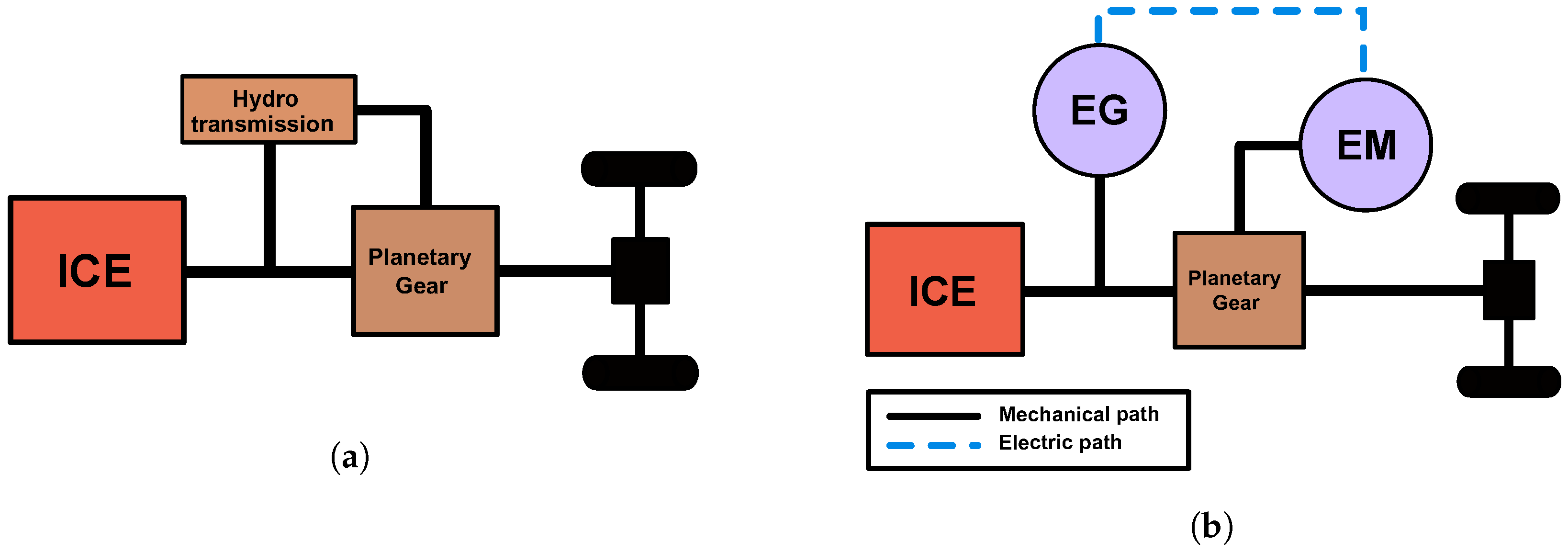
  • Depending on the power characteristics of the output, each machine could be controlled to act as a motor (propulsive element) or as a generator (braking element).
  • If no auxiliary ESS is considered (electric transmission), the electric system should operate as close as possible to the condition of power recirculation through the electric machines.
  • Thanks to the planetary gearbox work principles, in critical faulty conditions, the engine can be mechanically coupled to the wheels just by blocking the other input component of the mechanism.
The electric power split configuration, thanks to the presence of the ICE, may require smaller electric components, thanks to the fact that the main power contribution should be always taken from the engine shaft. Moreover, the system can achieve higher efficiency due to the better performance in power transfer of electric lines if compared with hydraulic pipes.

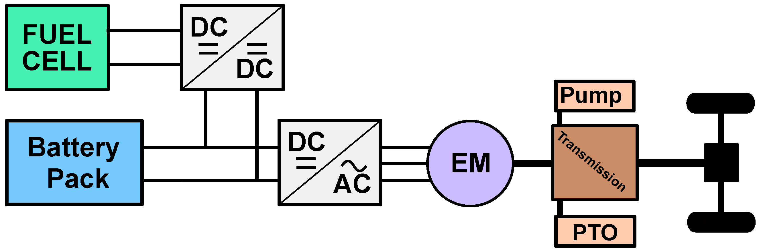
3.5. Fuel Cell Electric Powertrain

Fuel cell hybrid electric vehicles (FCHEVs) are currently of great interest as an alternative solution to full-electric vehicles. They aim to overcome the main limitations of a full-electric vehicle, namely, the working range and charging time, with the same feature of producing zero local emissions [69]. FCHEVs use hydrogen as the main energy vector instead of electric energy stored into a battery pack, with the advantage of higher energy density [70]. Hydrogen can be obtained through several techniques, from both renewable and nonrenewable resources [71]. Nowadays, most of the hydrogen is produced from fossil fuels, which surely is not optimal from an environmental point of view. Several other cleaner hydrogen production scenarios are currently under development in order to increase productivity and tackle the overall environmental footprint, using more and more renewable sources in the production chain [72]. To store the hydrogen on board the vehicle, different approaches can be taken. The most widely adopted is to store the hydrogen in gaseous form at a high pressure inside special tanks; however, another technique that is under investigation by researchers is to store it by absorption in metal hydride tanks [73]. In the first case, the high storage pressure helps increase the overall energy density of the tank, but requires proper attention at the design stage for both mechanical and safety reasons [74,75]. However, this type of storage technique allows for a refueling time comparable with traditional gasoline- or diesel-powered vehicles. In a FCHEV, hydrogen and oxygen are converted into electric energy and water through redox reactions occurring between the hydrogen ions coming from the anode side of the fuel cell and the oxygen to which the cathode is continuously exposed. In the reactions, electrons are moved from the anode to the cathode in order to achieve the final product: H2O. As described in Figure 7, a fuel cell hybrid electric tractor (FCHET) consists of a fuel cell stack (a series of elementary fuel cells) producing electric energy to power the electric machine/s installed in the powertrain. Usually, one or more auxiliary units (generally batteries or supercapacitors) are required to help the powertrain satisfy the fast dynamic of the external load and to avoid the fast degradation of the fuel cell [76]. When connecting more electrical power sources, the most difficult part is their interfacing on the same DC-Bus, which must provide power to the electronic drives of the electric machines. For this reason, several DC–DC power converters must be used, adding a non-negligible level of complexity and cost to the overall architecture, requiring specific energy management [77].
From the vehicle point of view, a fuel cell architecture should consider the integration of several components in the tractor layout: the fuel cell stack, the auxiliaries required for the FC system to operate (reactant supply systems, cooling pump, etc.), the hydrogen storage (gaseous tanks or metal hydride storage structures), the battery pack or the supercapacitors, and the DC–DC converters. Thus, according to the current state of the art of a commercial product, FCHETs would require a higher level of effort at the design and production stage than full-electric tractors, but the clear advantage given by the faster charging time and energy density of fuel cell tanks could represent a high potential in the upcoming years [78].

4. A New Methodology for Work Vehicle Classification: The New Hybridization Factor

In this section, a new updated version of the hybridization factor (HF) is proposed. In the literature, there are several definitions of hybridization factor, all with the same aim: to provide a classification criterion for electrified vehicles. Considering the automotive sector, one of the first formulations of the hybridization factor [79] is shown in Equation (1):
K e = P e m P I C E
where P e m and P I C E are the powers, available for vehicle traction, of the electric motor/s and internal combustion, respectively. K e can take a value between 0 (traditional internal combustion engine vehicles) and (full-electric vehicles). However, this definition might be scattered and ambiguous in meaning. Indeed, the final value that K e could assume (between 0 and + ) makes it almost impossible to establish a clear hybridization rank of the car. Furthermore, this definition fails when considering a series architecture hybrid vehicle. Indeed, in this case, the power available for traction is totally provided by the electric motor, whereas the ICE provides power to the electric generator, whose contribution to the hybridization factor is not even taken into account. Hence, according to Equation (1), for series architecture hybrid vehicles, P I C E is equal to 0 and K e is equal to infinity, assimilating a series hybrid vehicle to a full-electric one. Another definition of the HF is shown in Equation (2) [80,81]:
H F = P e m P e m + P I C E
where
-
P e m indicates the power delivered by the electric motors to propel the vehicle.
-
P I C E indicates the power of the internal combustion engine available to propel the vehicle.
In this way, the hybridization factor can take a value between 0, when the propulsion system is composed only of the thermal unit, and 1 for full-electric vehicles. In this way, HF represents a clear attempt to establish a well-defined level of hybridization of the vehicle. However, if this approach could be useful to describe the hybridization level of vehicles with parallel architectures (where the power contribution of the electric motor and of the ICE can sum up together on the same shaft), on the other side, this formula fails to describe the electrification grade of series hybrid vehicles.
Focusing on the working vehicle sector, the hybridization factor is more difficult to be defined. Indeed, in this case, the power delivered by the different propulsion systems must be used, not only for traction purposes, but also to execute several operations with connected implements. Therefore, a working vehicle presents at least two power paths: one for motion and one for working tasks. Furthermore, hybrid working vehicle power paths are often characterized by different architectures within the same vehicle (i.e., drive path presenting series architecture, whereas PTO path a parallel or full-electric architecture). For these reasons, Somà et al. proposed [23,24,82], an updated version of the hybridization factor, applicable to working machines, which takes into account the coexistence of different power paths:
H F W M = k · H F D r i v e + ( 1 k ) · H F L o a d
where
-
k is a coefficient that can take a value between 0 and 1 according to the machine work cycle, representing the overall power demand used for driving purposes on the total available;
-
H F D r i v e represents the hybridization factor for the powertrain in charge of driving the vehicle as defined in Equation (2);
-
H F L o a d represents the hybridization factor for the powertrain in charge of powering work tasks as defined in Equation (2).
As can be noted from Equation (3), the formulation of HF applied to work machines makes a clear distinction between the two main functions of these vehicles: driving ( H F D r i v e ) and working ( H F L o a d ). This evolution of HF with respect to the automotive sector is necessary in order to distinguish the wheel path from the other loads (i.e., mechanical implements or hydraulic tools) characterizing working machines, which may be comparable with the wheel power demand. In case of no available information about machine duty-cycle k, it can be assumed to be equal to 0.5 (same power demand on the different power paths). In this article, a new updated version of the hybridization factor for working machines is proposed. According to the authors, the definition of HF for working vehicles given in Equation (3) can still be improved, taking into account some elements that are fundamental for determining the electrification level of a working machine, but they have never been considered for HF calculation:
  • The battery pack, if present;
  • The electric generator, if present;
  • The amount of energy stored and how it is distributed among the different sources of energy in the vehicle;
  • The quality of the propulsion systems installed on the vehicle.
The new version of the hybridization factor for working vehicles can be written as follows:
H F W M * = k · H F D * + ( 1 k ) · H F L *
where
-
k is a coefficient that can take a value between 0 and 1 and represents the overall power demand used for driving purposes on the total power available;
-
H F D * represents the new hybridization factor definition applied to the driving powertrain;
-
H F L * represents the new hybridization factor definition applied to the load powertrain.
The new definition of the hybridization factor for each power path (namely, H F D * and H F L * ) in a tractor can be defined as follows:
H F P P * = P e m P e m + P I C E , n e t · P B P P B P + P e g 1 η E L C B P η E L C B P + η I C E C I C E
where
-
H F P P * is the hybridization factor definition for the single power path, driveline, or PTO (namely, H F D * and H F L * );
-
P e m is the power directly available to the drive shaft provided by the electric motor/s;
-
P I C E , n e t is the net power directly available on the drive shaft provided by the internal combustion engine but decremented by the power eventually taken by the electric generator in a series configuration;
-
P B P is the nominal power of the battery pack delivered to the electric motor/s, if present in the vehicle;
-
P e g is the nominal power of the electric generator delivered to the electric motor/s, if present in the vehicle;
-
η E L indicates the average efficiency of the electrical path;
-
η I C E indicates the average efficiency of the internal combustion engine;
-
C B P represents the battery pack capacity (in kWh) stored in the vehicle;
-
C I C E represents energy (in kWh) contained in the fuel tank of the vehicle.
According to this new definition, the hybridization factor can take values between 0 (no hybrid vehicles) and 1 (full-electric architecture). Furthermore, also electrified vehicles with electric transmission configurations present a 0 value of HF. Indeed, the definition of a hybrid vehicle currently available in the literature [83] considers all the vehicles whose energy is propelled from two or more sources. Thus, systems where the electric energy is obtained only by the combination of a generator and an ICE, although being electrified, cannot be considered as hybrid vehicles. Another fundamental element in electrified vehicle architectures, which rises from Equations (4) and (5), is the battery pack, considered in terms of both power and capacity. Thanks to the fast technological improvement of Li-ion batteries, different battery packs are present on the market for hybrid vehicles with the same architectures and power sizes. This issue must be considered to define the hybridization level of a vehicle. Indeed, for example, considering two vehicles with the same power sizes and fuel tanks, it is clear that the larger the battery capacity or power delivered, the larger the contribution the electrical path is able to give to propel the vehicle, hence its hybridization factor. Furthermore, Equation (5) investigates also where the electrical power within the vehicle comes from, comparing the electrical power of the accumulator with the total available considering the contribution of an electric generator. This ratio is crucial because it indicates how the mechanical power directly available to the drive shaft and provided by the electric motor comes from between “direct” electric power, given by the battery pack, and “indirect” electric power, given by the electric generator, hence by the internal combustion engine. The last features that the new formula of HF is able to take into account are the quality of electrical and thermal paths, thanks to the presence of their respective efficiencies. The approach proposed in Equations (4) and (5) aims to overcome limitations of the formulations proposed in the past for NRMM, avoiding misunderstandings when describing some particular architectures. However, the most innovative feature introduced by the new version of HF is that the contribution of each element that can characterize a hybrid or full-electric vehicle is now taken into account. To better highlight the improvements of the new HF formulation, a simple sensitivity analysis was performed considering two different powertrain configurations. The first configuration was a parallel hybrid configuration for both the PTO and the drive, while the second configuration was a parallel for the PTO and a series for the drive. As for the first case, the sensitivity analysis was performed, changing the battery pack capacity. In the second case, the parameters changed were the electric generator power and the battery pack capacity. In both cases, the power of the battery pack was estimated, considering 3C as maximum continuous discharge current. The results obtained are shown in Figure 8. For the parallel configuration, whose results of the analysis are shown in Figure 8a, the parameters used for the HF calculation were η E L = 0.85, η I C E = 0.35, P e m = 30 kW, P I C E , n e t = 60 kW, and C I C E = 500 kWh (≈45 L of diesel fuel); for the configuration with parallel PTO and series drive architecture, in the case of the analysis varying the electric generator power, whose results are shown in Figure 8b, the parameters used for the HF calculation were η E L = 0.85, η I C E = 0.35, P e m = 60 kW, P I C E , n e t = 30 kW, C I C E = 500 kWh, and C B P = 20 kWh, while in the case of varying the battery pack capacity, whose results are shown in Figure 8c, the parameters used for the HF calculation were η E L = 0.85, η I C E = 0.35, P e m = 60 kW, P I C E , n e t = 30 kW, C I C E = 500 kWh, and P e g = 30 kW. Analyzing Figure 8a, it is possible to highlight that the previous formulation of the HF does not take into account the capacity of the battery pack, which is instead crucial to determine what is the real use of electric energy and of fuel in the thermal engine. A vehicle with a higher battery pack is able to use a higher amount of electric energy; thus, a higher HF should be assigned. On the other hand, analyzing Figure 8b, it is possible to state that the older formulation overestimates the HF in case of a series configuration on the drive side. This is due to the fact that, considering the old formulation, the HF of a series configuration is always equal to 1, since the power of the thermal engine available at the output shaft is equal to zero. This limit is overcome with the new formulation. As for Figure 8c, the same considerations made for Figure 8a can be stated. The new HF formulation will be applied in the next section to understand where academy and industry are investing more effort in terms of research and development.

5. Implement Electrification

Tractors are a mobile platform able to generate power both for traction or for the attached implements required to complete specific field tasks. Some implements do not require additional power from the PTO: they are passively pulled by the tractor, and their efficacy depends on the work parameters (work depth, work width, etc.) and on the traction capabilities of the tractor–implement system [33,84,85]. On the other hand, there are implements relying on the power coming from the tractor through the PTO to activate mechanisms and tools to perform the work task [86,87,88]. Thus, in the most general case, traditional implement architectures can be described as in Figure 9a, where the power coming from the mechanical PTO of the tractor (it could be front or rear PTO) must be split among all the mechanical users. This happens through a mechanical coupler (usually a gearbox or a belt/chain system) distributing power directly to the directly connected devices (blades such as in a rotary harrow or a fan of an atomizer) or to one or more hydraulic pumps responsible for the conversion into hydraulic power for the hydraulic motors and actuators on the implement. The latter is usually considered when the hydraulic power need on the implement side is beyond the available hydraulic power provided by the tractor hydraulic pump. Moreover, in this case, the manufacturer has a higher freedom in the design stage of the hydraulic system on the implement side, being decoupled from the specification of the hydraulic system of the tractor (which can be different from one tractor to another).
Recently, the benefits of electric power have been explored also on the implement side [89,90,91]. As shown in Figure 9b, electric power on the implement side is split within a power distribution unit (PDU) to all the electric machines or actuators of the machine. The electric power may come from an electric interface between the tractor and the implement, implying the need for a generator and/or a battery pack on the tractor side [90]. In principle, the electric generator may be also installed on the implement side as a substitute for the hydraulic pump in the traditional architecture discussed before. Finally, mixed configurations are also possible, combining the two architectures in Figure 9a,b. In this case, the highest amount of power would be transferred by the mechanical PTO, while the electric energy would be used to actuate the less-power-demanding electric system.
The main goal of implement electrification is to reduce the energy losses related to the cardan shaft and to the hydraulic devices while introducing a higher level of controllability, thanks to modern electronic drives. Thus, the implement capabilities can improve in terms of both energy efficiency and productivity. This is very important especially for specialized tractors where PTO-powered implements are widely used and their level of automation can be further improved.

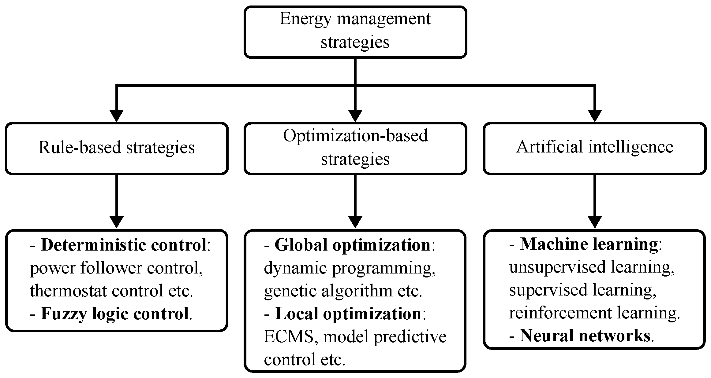
6. Control Strategies and Energy Management

The presence of two or more different power sources in a powertrain leads to the necessary development of a proper energy management strategy (EMS) [77,92]. The EMS should determine the power split between the different energy sources trying to achieve the optimal operating condition according to different objectives. The common objectives usually used in the literature are related to the minimization of the fuel consumption, the reduction of component aging, or both of them, considering their trade-off [93,94,95,96]. To enhance the performance of the EMS, accurate SOC estimation algorithms, aging evaluation models, and power capability predictions are required [97,98,99]. Generally, control strategies can be divided into rule-based strategies (RBSs), optimization-based strategies (OBSs), and artificial Intelligence control strategies (AICSs) [77]. RBSs are based on a rule table, formulated according to experience, previous information, intuition, etc., that determines the power allocation according to some predefined system state parameters; thus, they usually require a low computational effort and can be easily implemented in real time. RBSs can be divided into deterministic control and fuzzy logic control [100]. On the contrary, OBSs exploit optimization algorithms to achieve the optimal solution to the power allocation problem, according to the chosen objective function. With respect to RBSs, these strategies require a higher computational time, but can obtain better results. OBSs can be classified into global and local optimization-based strategies [101]. Generally, global optimization strategies, such as dynamic programming (DP), require the complete a priori knowledge of the work cycle, and thus cannot be implemented in real time. However, since they can reach a global optimization, they are a used as benchmarks for the other strategies or as a tool to determine rules to be used in RBSs [102]. Apart from DP, other widely adopted global optimization algorithms are genetic algorithm, game theory, and stochastic dynamic programming [103,104,105]. Instead, local optimization strategies, such as equivalent consumption minimization strategy (ECMS), are developed to minimize an instantaneous objective function, and thus can obtain a suboptimal solution and are suitable for being implemented in real time [106]. The goal of the ECMS is to minimize, at each time step, an objective function that represents the equivalent fuel consumption, which is evaluated by the sum of the fuel consumed in the ICE and the equivalent fuel consumption related to the battery discharge. To define the objective function, an equivalent factor must be defined and properly tuned. The equivalence factor can be fixed or, to enhance the optimality of the control, variable according to some predefined parameters, as in the case of adaptive ECMS [107]. As for the AICSs, they can be divided into two main categories: machine learning, which can be further divided into unsupervised, supervised, and reinforcement learning, and neural network [108]. Those strategies are characterized by having an adaptive capability to the problem of optimization; thus, they use computational techniques to learn from data and adaptively improve their performance [109]. Generally, they require a high amount of historical data to obtain an optimal control. Figure 10 shows a graphical representation that summarizes the classification of the existing EMSs for hybrid vehicles. In the literature, some studies regarding the development of energy management strategies for a hybrid powertrain designed for agricultural tractor have been proposed. These studies regard hybrid powertrains with an ICE or with an FC and full-electric configurations.

6.1. EMSs for Hybrid Tractors with ICE

Troncon et al. [110] simulated a rule-based charge-depleting strategy to control a plug-in parallel hybrid architecture. According to the strategy, the EM provided traction torque if the power requested by the overall vehicle exceeded the maximum power of the downsized engine. Mocera et al. [49,111] investigated, using both simulations and hardware-in-the-loop tests, a load follower strategy to control a parallel hybrid agricultural tractor. According to the strategy, the electric motor was controlled as a function of the engine load so that, at low loads, the powertrain operated using mainly the ICE, while at higher loads, also the electric motor was exploited. Jia et al. [112] investigated a series hybrid architectures using two different rule-based EMSs: a thermostat control and a power follower control. In the first case, the generator was turned off when the battery SOC was greater than a defined upper threshold value and was turned on when the SOC approached a lower threshold value. On the contrary, the power follower controller was designated so that the generator followed the power required by the EM when the SOC was within the threshold value. If the SOC level was below the lower limit, the generator provided maximum power to recharge the batteries. Simulations were carried out to compare the two control strategies in terms of fuel consumption and emission levels. Barthel et al. [113] introduced an EMS for hybrid tractors combining load point shifting based on an optimization algorithm with regeneration and boost based on heuristics. The authors considered a parallel hybrid configuration for the analysis. The load point shifting was designed to exploit the electric motor to adjust the operating point of the combustion engine to achieve better efficiency and lower fuel consumption. The strategy also included the regenerative braking and an electrical boost mode. Mocera et al. [53,64] investigated different powertrain architectures using dual-mode rule-based strategies. According to the proposed strategies, when the SOC level was higher than a threshold value, the powertrain operated in a charge-depleting mode, thus exploiting the batteries’ electrical energy to assist the ICE. On the contrary, when the SOC fell below the threshold value, the powertrain started operating in a charge-sustaining mode; thus, it tried to preserve as much as possible the battery SOC and to avoid an excessive depth of discharge. Dalboni et al. [114] proposed a case study about the design of a parallel hybrid agricultural tractor. As for the EMS, the powertrain operated in two main modes: full-electric and hybrid mode. The transition between the two modes was performed by the disengaging and engaging of a clutch between the ICE and the motor. The threshold value for the transition was optimized, considering the fuel consumption, engine running time, number of clutch engagements, and battery C-rate. The hybrid mode was characterized by submodes, namely, full ICE, battery charge, and power boost, which were selected according to the required power and the battery SOC. Zhang et al. [67] considered a parallel hybrid powertrain with a CVT downstream the coupling of the ICE and the electric motor. The authors compared, through simulations based on real data collected in the field during a rotary tillage operation, a global optimization strategy, based on DP, with an RBS power follower strategy, with the aim of minimizing the total cost of energy consumption. The results showed that the OBS reduced the total energy consumption cost by approximately 17%. Zhu et al. [115] compared an adaptive ECMS with a nonadaptive ECMS applied to a parallel hybrid with hydromechanical CVT on the ICE side. The basic principle of the ECMS is that the controller minimizes, at each sampling instant, an objective function that represents the equivalent consumption, which considers both the fuel and electrical energy consumptions. To evaluate this equivalent consumption, an oil-electric equivalence factor must be used, which can be constant or adjusted online. In the case of an adaptive ECMS, the equivalence is adjusted in real time. Simulations were carried out, showing that the adaptive ECMS was able to reduce the fuel consumption by 5–7%, depending on the simulated task, compared with the nonadaptive strategy. Zhang et al. [116] compared an ECMS, with the equivalence factor determined considering the costs per liter of oil and per kWh, with a rule-based power-following strategy. The powertrain topology was a parallel hybrid. Simulations showed that the ECMS reduced the fuel consumption by 5–6%. Dou et al. [68] considered a complex hybrid powertrain and proposed a control strategy with a multilayer structure: first, a demand power prediction algorithm, based on a neural network, was used; then an ECMS was exploited to optimize the power distribution between the engine and the electric motors. The equivalence factor of the ECMS was optimized with an offline genetic algorithm and converted into a lookup table to be suitable for an online control. Simulations showed that the adaptive ECMS reduced the equivalent fuel consumption by 8.4% compared with a simple rule-based strategy. Jia et al. [117] proposed three different OBSs to minimize the fuel consumption: a deterministic DP, an indirect method based on Pontryagin’s minimum principle, and a direct method based on nonlinear programming. The architecture considered in the paper was a series hybrid configuration. Simulations result indicated that the OBSs, compared with a benchmark rule-based strategy, offered good improvements, up to 5%, in fuel economy. Tebaldi et al. [50] investigated the modeling, the control, and the simulation of a hybrid electric architecture with a supercapacitor as an electrical onboard storage system. Moreover, the architecture featured two electrical machines: a generator and a motor. As for the EMS, a control strategy based on the concept of ICE minimum specific consumption path was presented. According to the strategy, the control logic decided the state of the vehicle at each time step on the basis of the current values of three decision variables: vehicle speed, required torque, and voltage drop across the supercaps. Five different states were defined. The vehicle state determined the proper torque demand for each of the three power sources (ICE, generator, and motor) in order to minimize the ICE fuel consumption, satisfy the power demand requested by the vehicle, and preserve the voltage level of the supercaps. Lee et al. [118] used an EMS based on power split ratio, defined as the ratio between the engine power and the total required power. Points of the power split ratio of the total required power were calculated by DP. Beligoj et al. [32] evaluated the economic feasibility of a parallel hybrid tractor using a life cycle cost analysis. Work cycles based on actual field measurements were considered. For the simulations, the adopted control strategy was a rule-based strategy, in which the torques provided by the engine and the motor were determined according to threshold curves. However, these threshold values were individual for each operating cycle and were chosen offline, and thus required the knowledge of the whole load cycle. According to the strategy, at low loads, the motor acted as a generator; at medium load, the powertrain operated in only an ICE mode; and at high load, the system operated in a hybrid mode with the motor providing torque to support the engine. Ghobadpour et al. [119] aimed at developing an EMS for a plug-in hybrid electric tractor (PHET) to minimize fuel consumption and increase the operating range. The authors considered an extended-range solar assist plug-in hybrid electric tractor for light agricultural applications. The powertrain topology was a series hybrid with three motors, with a biogas-fueled engine generator to prevent energy shortage in the batteries. The EMS was composed of two main layers, the first used to recognize the working condition (light, moderate, and heavy) on the basis of the statistical features of measured data (required power, speed range, etc.), and the second used to allocate the power between the different onboard sources. To determine the power split, a multimode fuzzy logic controller (MFLC), composed of three modes, was designed. Each mode considered the requested power and the battery SOC level as inputs and determined the power that the generator had to provide. According to the strategy, during light work conditions, the powertrain operated in a charge-depleting and charge-sustaining mode, in heavy conditions in a charge-sustaining mode, and in moderate conditions in a charge-blending mode. The proposed strategy was compared, by means of simulations, with a thermostat controller, with a genetic algorithm-optimized fuzzy controller in which the fuzzy controller parameters were optimized by means of a genetic algorithm to achieve online near-optimal control for the known working cycles, and with DP. Simulations with three different work cycles were performed, and the results showed that the MFLC obtained a fuel consumption reduction of around 12–14% compared with the thermostat controller; moreover, it was close to the optimal controllers. As for machine learning strategies applied to agricultural tractors, Liu et al. [120] investigated an EMS based on deep reinforcement learning for a series hybrid tractor. The algorithm, defined as deep deterministic policy gradient algorithm, was tested using simulations and showed results close to DP. Considering the existing studies on control strategies, almost all of them were performed using simulations, with a predominant use of the MATLAB/Simulink platform. Generally, those simulations are carried out modeling each element of the powertrain. The numerical models include the ICE and motor models, which are generally made using their efficiency maps; the battery model; usually realized using an equivalent circuit model; the drivetrain model; and the longitudinal dynamic model, generally constituted by a simple model that considers only one direction of motion and evaluates the power requested by the vehicle at each time step. However, in [68], a hardware-in-the-loop system was designed to test the real-time performance of the proposed strategy. Moreover, some prototypes were realized. In detail, the hybrid architectures proposed in [114,119] were built. In addition, the design of an eCVT transmission for agricultural tractors was proposed, and a prototype was realized in [65].
Table 2 summarizes the characteristics of the tractor architectures studied in the literature presented above. It reports all the necessary data, when available, to calculate the new H F W M * . To calculate the hybridization factor, several assumptions have been made, not having more detailed data. However, the assumptions where considered equal among all the calculations for the sake of consistency of the results. In particular,
  • An electrical path efficiency η E l = 0.85 ;
  • An ICE overall efficiency η I C E = 0.3 ;
  • An ideal energy content for diesel fuel of 11.85 kWh/L;
  • A nominal battery power as P B P = 3 N o m . C a p a c i t y assuming LiFePO4 cells;
  • k = 0.5 because of the lack of information about the work cycles of the tractors (there is still a lack in the literature about tractor work cycle standardization) as suggested; in [23,24,82]
  • The diesel tank capacity in L was estimated looking at tractors with a similar size of the diesel engine.
Table 2. Classification of hybrid tractor architectures investigated in the scientific literature. In the architecture, column P. is for parallel configuration, and S. is for series configuration.
ArchitectureEm PowerGen Power
Model Year Drive PTO Drive (kW) PTO (kW) Drive (kW) PTO (kW) ICE (kW) Tank (L) BESS (kWh) HF WM *
Zhang et al. [67]2023P.P.404000605022.40.44
Zhu et al. [115]2022P.P.45450013215016.20.26
Zhang et al. [116]2023P.P.30300016218025.20.17
Dou et al. [68]2022S./P.P.65 + 50500014515082.30.39
Jia et al. [117]2019S.S.90-90-10485--
Troncon et al. [110]2019P.P.9.29.20055.450--
Jia et al. [112]2018S.S.----10410--
Barthel et al. [113]2014P.P.-----10--
Tebaldi et al. [50]2021P.P.----48010--
Lee et al. [118]2016P.P.9520050503.20.34
Beligoj et al. [32]—T12022P.P.99005550210.17
Beligoj et al. [32]—T22022P.P.262600151150240.16
Beligoj et al. [32]—T32022P.P.141400193200140.07
Ghobadpour et al. [119]2021S.S.2 × 21158.88.88.84016.80.86
Dalboni et al. [114]2019P.P.----551025-
Liu et al. [120]2023S.S.----300---
Mocera et al. [53]—S12022S.P.54545405450160.51
Mocera et al. [53]—S22022S.P.63545405450160.51
Mocera et al. [53]—P12022P.P.3030005450160.38
Mocera et al. [53]—P22022P.P.2222005450160.32
Mocera et al. [53]—EH2022P.P.2222005450160.32
Mocera et al. [64]2022S./P.P.30353505450160.40
It is interesting to note how the architectures proposed in the literature are mainly located in the mild-hybrid, low full-hybrid region apart from very special concepts such as the one proposed by Ghobadpour et al. [119] for a small tractor with a small range extender. The reasons behind that could be related to the difficulties in vehicle integration of more complex architectures or to the limitations of current storage systems, which still require a lot of onboard space to store an adequate amount of electric energy to accomplish the daily work tasks. Nevertheless, the next section will show how, despite the limitations of the current state of the art in energy storage systems, a lot of research is also conducted on full-electric tractor configurations because of the architecture simplicity and benefits they can bring to specific types of work.

6.2. EMSs for Hybrid Tractors with FC

Martini et al. [121] investigated a fuel cell/battery powertrain for orchard tractors using an EMS in which the power split was determined according to a function considering the power request as the main input parameter, similar to a power follower control. Moreover, penalty factors were introduced to take into account the SOC and the maximum allowable C-rates of the battery pack. According to the simulation results, the strategy also behaved as a charge-sustaining strategy. Tritschler et al. [122] considered an architecture with a fuel cell as primary power source and a Li-Ion battery pack as secondary source, both connected to the DC bus through DC–DC converters. As for the EMS, three control strategies were considered: a rule-based strategy, a gliding average strategy, and an ECMS. In the rule-base strategy, the current set point of the fuel cell is varied according to the external load and to the battery state of charge, with constraints regarding the bad efficiency regions (very low or very high power) and fuel cell current slope limitations. Instead, the gliding average strategy was based on a simple gliding average of the requested power, with again corrections related to the battery pack SOC. Simulations were performed considering different work cycles. The results showed that the ECMS appeared to be the best control strategy; however, the differences among the different EMSs were not so relevant. Xu et al. [123] developed an EMS for a powertrain composed of a fuel cell connected to the bus DC with a DC–DC converter and with LiFePO4 batteries and ultracapacitors as auxiliary power sources, which were instead directly connected to the bus. The authors designed a control strategy based on a multilayer power decoupling, following the principles that the fuel cell should operate at its optimal efficiency region and that the power distribution between batteries and ultracaps should respect constraints related to their SOC, to avoid overcharge and overdischarge. Given the load demand power, the first layer used a Haar wavelet transform to decouple the power signal into a low-frequency part and a high-frequency part. The high-frequency part was handled by the supercaps, while the low-frequency part was furthermore decoupled using a second layer based on logical rules. The output of the second layer was a steady-state power signal, handled by the FC, and a subhigh frequency power signal, handled by the batteries. The controller was tested and calibrated using a hardware in the loop test. Compared with single-layer control strategies, such as fuzzy control and power following control, the proposed multilayer EMS showed promising improvements in terms of fuel cell average efficiency and equivalent fuel consumption. Moreover, the proposed strategy recorded the lowest oscillations on the FC power output. Yang et al. [124] proposed an EMS, for a fuel cell/battery powertrain, which aimed at maintaining the battery SOC, optimizing the fuel consumption and limiting the change rate of the fuel cell output power according to its dynamic characteristic. For maintaining the battery SOC, the thermostat control strategy was adopted. Four states were defined based on the available hydrogen in the tank and on the battery SOC. According to these states, the powertrain operated with the battery alone, with both the fuel cell and battery providing power and with the fuel cell providing power both for traction and to recharge the batteries. When in the state corresponding to a hybrid mode, in which both the fuel cell and battery provided power, the power distribution between the two power sources was determined using a power follower controller, according to which the fuel cell power was determined based on the power demand and adjusted by considering the SOC value of the battery. However, to consider the constraints related to the charge rate in the fuel cell power output, a fuzzy logic controller was introduced. The fuzzy rules were furthermore optimized offline, considering both energy consumption and fuel cell durability. The proposed strategy was compared, by means of simulations, with a simple fuzzy logic controller, a power follower controller, and a DP, showing a reduction of 2% in terms of equivalent hydrogen consumption compared with the FLC and PF controllers. The DP showed, as expected, the best results in terms of equivalent hydrogen consumption, but it did not take into account the fuel cell durability. As a consequence, the best result in terms of degradation of the FC was obtained using the proposed strategy. All of the proposed studies were performed using simulations or hardware-in-the-loop systems; no full-scale prototype was built.

6.3. Control Strategies for Full-Electric Powertrains

With respect to hybrid vehicles, full-electric architectures apparently do not require an EMS since they do not have two onboard different energy sources, but only feature the electrical energy stored in the energy storage system. However, in full-electric vehicles, an intelligent use of the electrical energy is particularly challenging, in order to extend as much as possible the autonomy without compromising vehicle performance. Therefore, an optimization of the energy flows in electric vehicles is still mandatory to preserve battery performance, enhance traction efficiency, or optimize the thermal management of the powertrain [125,126,127,128]. Depending on the case study, the optimization of the control of the electric vehicle can be performed at different levels. Gade et al., Lu et al., and Chen et al. [129,130,131] focused on the optimization of the control of the tractor electric motor. These studies adopted different control techniques to enhance the dynamic behavior of the motor drive, reduce torque and current ripples, minimize the losses. A particular case of interest in the field of agricultural machinery is related to dual-motor configurations. As a matter of fact, agricultural tractors might have to operate in harsh conditions, with difficult and steep terrain. A dual-motor configuration allows for improvements in terms of traction efficiency, slip control, and consequently, energy consumption [132]. De Melo et al. [133] focused on a slip control algorithm for a two-wheel drive electric tractor. The two motors were controlled separately in order to maintain the slip of the wheels within an acceptable range and thus enhance the efficiency and the autonomy. The proposed control was tested on an experimental electric tractor prototype. Li et al. [134] proposed a dual-motor configuration with a dual-input coupling system featuring a planetary gear. The system can operate in three driving modes, two with a single motor, in which only one of the motors is active, and one with a dual-motor coupling drive, in which the two motors operate simultaneously with the planetary gear combining their power. The different driving modes can be selected by engaging or disengaging two brakes placed on the output shafts of the electric motors. In this case, to achieve optimal efficiency, a real-time EMS was developed to choose the best operating mode and, in case of dual-motor operation, to determine the optimal power distribution. In detail, at each point, the power distribution was determined by minimizing a cost function, related to the power delivered by the battery. In addition, to avoid excessive mode switching, a mode stability control was developed. Wang et al. [135] presented a co-optimization EMS for a dual-motor electric tractor configuration. The proposed EMS consisted of a demand torque calculation method and a driving torque distribution algorithm. The first one evaluated the torque demand according to the driver intentions and the actual vehicle working conditions using a nonlinear PID controller, while the second allocated the power between the two motors considering an objective function, which took into account the economy and stability, and using a swarm intelligence algorithm. The authors compared the proposed EMS with a simple rule-based strategy using an HIL platform, on which they emulated three different working conditions: plowing, rotary tillage, and transportation. Results showed that the novel EMS managed to improve the efficiency and the stability in terms of driving jerk. Zhang et al. [136] proposed a control strategy for a dual-motor electric tractor based on travel speed and wheel slip. First, the optimal wheel slip was calculated using a calculation method that took into account the operating conditions. This step was necessary since the optimal wheel slip for achieving the optimal traction efficiency is related to some parameters, such as the wheel load, which are not constant during work activities on the field. Then, according to the values of optimum driving wheel slip obtained in the first step, the torques of the two motors were controlled individually using a sliding mode algorithm. The proposed control algorithm was tested using an HIL platform, showing an improvement of 6% of the traction efficiency. Yu et al. [137] instead applied a torque calculation strategy, divided into basic torque and compensation torque calculation, and a particle swarm optimization algorithm in combination with a fuzzy controller to determine the optimal torque distribution between the two motors. In this configuration, one motor was used as “main motor” and the other as “speed regulating motor”. The effectiveness of the strategy was tested using a bench test and a drum test stand. Zhang et al. [138] designed, considering the power requirements of the vehicle, a power coupling device for a dual-motor configuration, which allowed for a different combination of power flows from the motors to the wheels and the PTO. The authors adopted a control strategy based on instantaneous optimization to distribute the power between the two units. However, apart from dual-motor configurations, other particular solutions have been proposed for electric tractors. The same research group [139] proposed an electric tractor powertrain with a battery position adjustment structure. By means of an electric cylinder, a real-time adjustment for the battery pack position was performed so that it was possible to change the load distribution of the tractor in order to achieve a better traction efficiency according to the actual work conditions. However, this system had some limitations related to the time response of the position adjustment system due to the heavy weight of the battery pack. Therefore, other systems must be introduced to compensate this limit. A field test platform for the electric tractor was developed to experimentally validate the effectiveness of the proposed control. Another case of EMS applied to a full-electric vehicle was proposed by Long et al. [44]. In this case, the need for an EMS was motivated by the presence of two different electrical storage systems, namely, a battery pack and supercapacitors. The proposed architecture featured a double motor structure, which was designed to allow for an independent speed regulation of driving and working loads, enhancing the adaptability of the vehicle to operate in different conditions. The electric power allocation was split between the battery pack and the supercaps using an online wavelet transform, which decompose the signal into high- and low-frequency components. In addition, a power regulation coefficient, which adjusts the power allocation according to the supercapacitors’ terminal voltage, was introduced.

7. Hybrid/Electric Agricultural Tractors: Prototypes and Industrial Investigations

In this section, an overview about the most interesting industrial cases about tractor electrification will be provided. According to the literature, the very first attempt of tractor electrification was made in 2009 by a Belarusian company with their 3023 hybrid model [61,140]. The concept, shown in Figure 11, consisted of a series hybrid tractor equipped with a 220 kW diesel engine coupled to a 220 kW electric generator, an electrical motor of 183 kW connected to the wheel transmission, and an additional 55 kW electric motor for a front PTO completely powered in series configuration. To complete the architecture, an electric interface of 172.5 max kW was made available for electric implement or different purposes that were not investigated by the time the concept was designed and produced. It is interesting to observe the absence of any kind of electrical storage on board, configuring this architecture more as an electric transmission rather than a hybrid configuration. In the end, all the power was generated from the diesel engine.
The second concept proposed in this review article is RIGITRAC EWD 210. The solution, developed by a Swiss company and TU Dresden in 2011, was very ambitious at that time. This tractor was a series hybrid configuration with five electric motors [141] (Figure 12).
The prototype was equipped with 91 kW diesel ICE, an electric generator of 85 kW, and four 33 kW electric motors directly splined to the vehicle wheels. The electrical generator was linked both to the ICE and to the PTO; thus, the PTO transmission was organized as a parallel architecture. At the same time, the electric generator provided the electric energy to the motor wheels for traction purposes. Hence, traction transmission presented a series architecture. Additionally, in this case, there was no presence of an electrical storage system. There are several reasons that made this prototype very interesting and quite innovative for that time, such as the presence of the in-wheel motors, but also the possibility to attach electric implements (with a maximum of 80 kW AC or DC power) and to brake with the electric motors. However, brake resistors were necessary to dissipate the energy developed during braking due to the lack of a battery pack to store the excess electrical energy.
In 2013, John Deere, with its 6210 RE (Figure 13a), and in 2015, CLAAS, with its ARION 650 Hybrid (Figure 13b), proposed two concepts of hybrid tractors with similar architectures [142,143]. The design proposed by the two companies included an electrical machine operating as a generator to provide electric energy for the implements’ interface. In the case of CLAAS ARION 650, thanks also to the presence of a 5.75 kWh battery pack, the electric machine could also help the driveline in a parallel configuration. However, its main duty was to provide up to 90 kW of power for the electric implement interface that, for the first time, was tested with an electrified implement (or at least, this is the very first electric implement with data available in the literature according to the authors’ knowledge).
The advent of commercial Li-ion batteries allowed for the exploration of the first full-electric tractor concepts. In 2016, John Deere presented its first full-electric tractor: SESAM [144,145]. The powertrain architecture, shown in Figure 14, was mainly composed of two electrical machines, characterized by 150 kW power each, and a battery pack of 130 kWh. The two electrical motors had two different purposes, since one was mechanically linked to the transmission for motion, and the other one was linked to the PTO.
In 2017, the German manufacturer Fendt presented its first full-electric tractor: Fendt e100 Vario. The solution made by Fendt [146] provided one electrical motor generator with a nominal power of 50 kW, in substitution for a traditional internal combustion engine, and a battery pack of 100 kWh. The electrical machine provided power both for motion purposes and PTO. Furthermore, the tractor had the possibility to interface also with electrical implements, thanks to the presence of a consistent electrical storage system up to 150 kW peak power. The architecture of Fendt e100 Vario is shown in Figure 15.
In 2018, the Italian company Del Morino, specializing in the design of small-size tractors, presented the first “completely” full-electric tractor: RINO (Figure 16). The solution proposed, currently available on the market, is composed of two electric motors, one for motion purposes and one for the hydraulic power, both 9 kW of nominal power. The tractor makes available an electrical interface at 240 V for electric implements. In this case, there is no traditional PTO, so this kind of tractor is compatible only with electrical implements. The energy is stored in an 18 kWh battery pack at 48 V [147].
In the same year, also the Swiss company Rigitrac presented its first prototype of a full-electric tractor: SKE 50. It consisted of a full-electric tractor equipped with five electrical motors and an electrical storage system of 80 kWh capacity. The vehicle presented two electric motors for traction (one for each axle) with 50 kW of maximum power each, two 23 kW electric motors for the front and rear PTO, and the last one was to provide power to the hydraulic system pump [148]. The architecture is shown in Figure 17.
Still in 2018, the Italian tractor manufacturer Carraro proposed their idea of a hybrid tractor: Carraro Ibrido [149]. This prototype presented a parallel architecture, and it was equipped with a 55 kW diesel internal combustion engine and a 20 kW electric motor. Thanks to its layout, the tractor was able to operate with three different settings: traditional mode (only the ICE working), hybrid mode (the ICE and the electric motor acting together), and full-electric mode (only the electric motor working). The architecture was completed with the presence of a 25 kWh battery pack. The Carraro Ibrido architecture is shown in Figure 18.
With the arrival of 2020s, the stage V regulation on diesel engine emissions stimulated an increasing interest also in the environmental performances of agricultural tractors [9,150]. Several tractor manufacturers engaged the challenge of designing hybrid or full-electric tractors, especially for those used in orchards or vineyards. In 2021, the Italian company Landini presented its first hybrid tractor concept: Landini REX4 Electra [151]. The design proposed fell in the category of series hybrid architectures and presented an electrical generator linked with a 110 HP internal combustion engine. Together with the presence of a Li-ion battery pack, it provided power to a full-electric front axle consisting of two independent electric motors (12 kW of power each) directly linked to each wheel to improve vehicle cornering capability. Instead, the ICE provided power to the rear axle and to the PTO. The architecture of the concept proposed is shown in Figure 19.
In the same year, another Italian manufacturer, Antonio Carraro, specializing in the production of compact tractors, proposed its first prototype of a hybrid tractor: Antonio Carraro SRX Hybrid [152]. The solution proposed consisted of a parallel hybrid solution with a 55 kW diesel internal combustion engine coupled with a 20 kW electric motor. The solutions was completed with the presence of a 6 kWh battery pack. In this way, the electric motor was able to provide boost power to the transmission whenever necessary (Figure 20).
Still in 2021, there was also space for a full-electric tractor. Indeed, a small company from California, Solectrac, presented its concept of a full-electric tractor, Solectrac e70N, now available on the market. It is a compact electric 4WD tractor equipped with a 52 kW electric motor used to propel both wheels and implements through the mechanical PTO [153]. The architecture is completed with a 60 kWh battery pack and is shown in Figure 21.
In 2022, both Landini and Antonio Carraro introduced two new prototypes of electrified tractors. In particular, Landini presented a new prototype of a hybrid tractor: Landini REX4 Full Hybrid [154]. According to their latest design, the powertrain consisted of a parallel hybrid architecture with the possibility to switch in a full-electric mode (Figure 22).
In particular, the 55 kW ICE combustion engine was coupled with an electric motor of 50 kW powered by a Li-ion battery pack of 30 kWh. In a full-hybrid mode, the electric motor provided up to 25 kW to the powertrain, whereas the full-electric mode was possible, thanks to the presence of a second electric motor of 15 kW of power to supply hydraulic systems. Instead, Antonio Carraro showed its first full-electric prototype: Antonio Carraro eSP. This vehicle was a small-size electric tractor equipped with a 25 kW electric motor and a 32 kWh battery pack. In this case, the architecture proposed by the engineers of Antonio Carraro aims to substitute the ICE with the electric motor, so each load present in the vehicle was powered by it. The same architecture was also considered by the Japanese manufacturer Kubota and the American company Monarch, and in the same year, they presented their small-size full-electric tractors, Kubota LXe-261, equipped with a 19.1 kW electric motor and a 25 kWh battery pack [155], and the MK-V model, equipped with an electric motor, able to develop up to 55 kW [156]. The architecture of these vehicles is shown in Figure 23.
The latest model shown in this study was developed by GOLDONI Keestrack and presented in 2022: GOLDONI Keestrack B1e [157]. It was a full-electric orchard tractor with each main load of the tractor powered by a dedicated electrical motor. Hence, the vehicle was equipped with five different electrical motors: the first with 35 kW of nominal power for traction, two electrical motors (14 kW and 9.5 kW) for rear/front PTOs, a 15 kW electric motor for hydraulic systems, and finally, a 4.5 kW electric motor to power the heat pump. Furthermore, the vehicle was provided with a 50 kWh battery pack. The architecture of B1e is shown in Figure 24.
In Table 3, all the industrial cases shown in this section are resumed. The new H F W M * was calculated, where possible, according to the same assumptions used for Table 2. It is important to note that the used values were taken from the literature or word press available, and thus must be considered as a representative value; they do not represent data from datasheets or technical sheets. However, these data allowed for tracing the current trend that the industry is following. At the moment that this review paper was written, mainly two research and development lines were established:
  • Research and development of mild-hybrid or small full-hybrid configuration for a small–medium tractor size in the 50–80 kW range;
  • Research and development of full- electric tractors in the small size factor with a power range below 50 kW.
Table 3. Classification of industrial cases.
ArchitectureEm PowerGen Power
Model Year Drive PTO Drive (kW) PTO (kW) Drive (kW) PTO (kW) ICE (kW) Tank (L) BESS (kWh) HF WM *
Belarus 3023e2009S.S.1835522022022020000
Rigitrac EWD 1202011S.ICE/S.4 × 3308580918500
John Deere 6210 RE2013ICEICE/S.00020665000
CLAAS ARION 6502015P.P./S.90400901363305.72 *0.49
John Deere SESAM2016F.eF.e150150----1301
Fendt e100 Vario2017F.eF.e5050----1001
Del Morino Rino2018F.eF.e99----181
Rigitrac SKE 502018F.eF.e5046----801
Carraro Ibrido2018P.P.2020005550250.31
Landini REX 4 Electra2021ICE/S.ICE2 × 120-08050--
A. Carraro SRX Hy2021P.P.202000555060.28
Solectrac e70N2021F.eF.e5252----601
Landini REX 4 Full Hy2022P.P.2525005550300.36
A. Carraro eSP2022F.eF.e2525----321
Kubota LXe-2612022F.eF.e1919----251
Monarch MK-V2022F.eF.e5555-----1
GOLDONI B1e2022F.eF.e3523.5----501
* P b a t t was given in [142] as equal to 120 kW.
The two research lines are more or less aligned with the research trends from the academic world. According to the authors, the main driving force for these two development lines is the need for more efficient tractors with the same level of performance of their traditional counterparts, but with engine downsizing as requested by the stage V regulation (at least in Europe). Several manufacturers are investing in parallel hybrid configuration in order to help the smaller-engine reaching peak power capabilities of the traditional counterpart, when the work load has peaks in the power demand. Moreover, the parallel hybrid configuration can be integrated into the existing architecture with a low impact on the traditional tractor layout, helping the modularity of the future production lines required. Although a higher level of H F W M * would introduce more features and a higher level of improvements, the higher complexity in terms of integration into existing platforms will represent a strong limitations to their exploration in commercial products, at least until some manufacturers will decide to design a specific tractor platform developed from the beginning for a full-hybrid configuration, possibly with series architectures.
In some specialized tractors’ category, especially for small tractor sizes, full-electric configurations may be considered as an opportunity because of the typical daily work cycle. The overall need for energy could be satisfied by a relatively small battery pack; thus, the vehicle could benefit from the simple transition from a traditional diesel-powered powertrain to its electric counterpart. The main limitation, in this case, would be the cost increase due to the addition of all the electric and electronic systems on a machine category which, for its size, is expected to not be too expensive.

8. Conclusions

In this review paper, the authors wanted to show the current state of the art in the field of agricultural tractor electrification, giving an overview of the current trends in research and development in both the academia and industry. As highlighted, the efforts of both worlds are now converging to specific tractor categories and tractor powertrain configurations that are reasonably easy to be integrated into existing tractor layouts, at least in some specialized tractor categories. However, the academia still keeps conducting research on more advanced powertrain configurations to give more space for performance optimization, thus introducing power-split mechanisms in the driveline or completely decoupling the ICE from the mechanical loads to better use the fuel energy content. The scientific literature is also exploring the possible use of fuel cell stacks as a power source for tractors. The idea is to use hydrogen as an alternative to diesel to have the benefits of an electrified powertrain but without the limitations of full-electric configurations, namely, the low energy density and difficulty of fast-charging the battery pack. The use of hydrogen-powered tractors could be pursued if more circular models for the hydrogen production, involving the farm itself, will be investigated in the next years. Moreover, the high cost of fuel cell systems is still a barrier that hinders their diffusion in tractors’ powertrains. As long as these aspects are not addressed, the architectures that will probably arrive to the market first will be hybrid parallel configurations, with small battery packs that will increase in capacity with time when the benefits of full-electric operations will be appreciated by the final users. In this context, a new hybridization factor definition was proposed in order to give updated metrics for the classification of hybrid vehicles. With respect to the previous formulations of the HF available in the literature, additional parameters, such as battery pack properties, are considered in the new metrics. To highlight the improvements of the new definition, a sensitivity analysis was conducted. Other architectures that will soon arrive to the market will surely be full-electric tractors at a small power size below 50 kW. Depending on the specific applications, some will allow an easy transition of existing platforms into full-electric ones that could also have success if the proper balance between electric conversion costs and overall benefits during the tractor life will be correctly balanced. The reasons for this trend can be found in the specific properties of hybrid and full-electric powertrains. Full-electric tractors are simple to integrate and to control; moreover, they allow for additional features, such tractive performance optimization in multimotor configurations, and produce local zero emissions. On the other hand, for bigger tractors, which may require high power and endurance, hybrid tractors are a more feasible solution because of the higher energy density of diesel fuel and the possibility of fast refueling.

Author Contributions

All authors contributed equally to this work. All authors have read and agreed to the published version of the manuscript.

Funding

This research received no external funding.

Data Availability Statement

Data retreived from scientific literature in the reference section.

Conflicts of Interest

The authors declare no conflict of interest.

Abbreviations

The following abbreviations are used in this manuscript:
4WD4 wheel drive
ACalternating current
AICSartificial intelligence control strategies
BESSbattery energy storage system
CANcontrolled area network
CVTcontinuously variable transmission
DCdirect current
DOCdiesel oxidation catalyst
DPdynamic programming
DPFdiesel particulate filter
ECMSequivalent consumption minimization strategy
eCVTelectric continuously variable transmission
EGRexhaust gas recirculation
EMSenergy management strategy
FCfuel cell
FCHETfuel cell hybrid electric tractor
FCHEVfuel cell hybrid electric vehicle
FETfull electric tractor
FLCfuzzy logic controller
GHGgreenhouse gas
HFhybridization factor
HVACheating, ventilation, and air conditioning
ICEinternal combustion engine
LiFePO4lithium iron phosphate
Li-ionlithium-ion
MFLCmultimode fuzzy logic controller
NRMMnonroad mobile machineries
OBSoptimization-based strategy
OEMoriginal equipment manufacturer
PDUpower delivery unit
PFpower follower
PHETplug-in hybrid electric tractor
PTOpower take-off
RBSrule-based strategy
SCRselective catalyst reduction
SOCstate of charge

References

  1. O’Regan, A.C.; Nyhan, M.M. Towards sustainable and net-zero cities: A review of environmental modelling and monitoring tools for optimizing emissions reduction strategies for improved air quality in urban areas. Environ. Res. 2023, 231, 116242. [Google Scholar] [CrossRef] [PubMed]
  2. Toscano, D. The Impact of Shipping on Air Quality in the Port Cities of the Mediterranean Area: A Review. Atmosphere 2023, 14, 1180. [Google Scholar] [CrossRef]
  3. Mofolasayo, A. Assessing and Managing the Direct and Indirect Emissions from Electric and Fossil-Powered Vehicles. Sustainability 2023, 15, 1138. [Google Scholar] [CrossRef]
  4. Tait, K.N.; Khan, M.A.H.; Bullock, S.; Lowenberg, M.H.; Shallcross, D.E. Aircraft Emissions, Their Plume-Scale Effects, and the Spatio-Temporal Sensitivity of the Atmospheric Response: A Review. Aerospace 2022, 9, 355. [Google Scholar] [CrossRef]
  5. Oreggioni, G.D.; Mahiques, O.; Monforti-Ferrario, F.; Schaaf, E.; Muntean, M.; Guizzardi, D.; Vignati, E.; Crippa, M. The impacts of technological changes and regulatory frameworks on global air pollutant emissions from the energy industry and road transport. Energy Policy 2022, 168, 113021. [Google Scholar] [CrossRef]
  6. Zhang, Y.; Zhang, Y.; Zhu, H.; Zhou, P.; Liu, S.; Lei, X.; Li, Y.; Li, B.; Ning, P. Life cycle assessment of pollutants and emission reduction strategies based on the energy structure of the nonferrous metal industry in China. Energy 2022, 261, 125148. [Google Scholar] [CrossRef]
  7. Wollenberg, E.; Richards, M.; Smith, P.; Havlík, P.; Obersteiner, M.; Tubiello, F.N.; Herold, M.; Gerber, P.; Carter, S.; Reisinger, A.; et al. Reducing Emissions from Agriculture to Meet the 2 °C Target. Glob. Chang. Biol. 2016, 22, 3859–3864. [Google Scholar] [CrossRef]
  8. Golasa, P.; Wysokiński, M.; Bieńkowska-Gołasa, W.; Gradziuk, P.; Golonko, M.; Gradziuk, B.; Siedlecka, A.; Gromada, A. Sources of Greenhouse Gas Emissions in Agriculture, with Particular Emphasis on Emissions from Energy Used. Energies 2021, 14, 3784. [Google Scholar] [CrossRef]
  9. Martelli, S.; Mocera, F.; Somà, A. Carbon Footprint of an Orchard Tractor through a Life-Cycle Assessment Approach. Agriculture 2023, 13, 1210. [Google Scholar] [CrossRef]
  10. Pradel, M. Life cycle inventory data of agricultural tractors. Data Brief 2023, 48, 109174. [Google Scholar] [CrossRef]
  11. Platis, D.; Anagnostopoulos, C.; Tsaboula, A.; Menexes, G.; Kalburtji, K.; Mamolos, A. Energy Analysis, and Carbon and Water Footprint for Environmentally Friendly Farming Practices in Agroecosystems and Agroforestry. Sustainability 2019, 11, 1664. [Google Scholar] [CrossRef]
  12. Mantoam, E.J.; Angnes, G.; Mekonnen, M.M.; Romanelli, T.L. Energy, carbon and water footprints on agricultural machinery. Biosyst. Eng. 2020, 198, 304–322. [Google Scholar] [CrossRef]
  13. Hagan, R.; Markey, E.; Clancy, J.; Keating, M.; Donnelly, A.; O’Connor, D.J.; Morrison, L.; McGillicuddy, E.J. Non-Road Mobile Machinery Emissions and Regulations: A Review. Air 2023, 1, 14–36. [Google Scholar] [CrossRef]
  14. Lovarelli, D.; Bacenetti, J. Exhaust Gases Emissions from Agricultural Tractors: State of the Art and Future Perspectives for Machinery Operators. Biosyst. Eng. 2019, 186, 204–213. [Google Scholar] [CrossRef]
  15. Bacenetti, J.; Lovarelli, D.; Facchinetti, D.; Pessina, D. An environmental comparison of techniques to reduce pollutants emissions related to agricultural tractors. Biosyst. Eng. 2018, 171, 30–40. [Google Scholar] [CrossRef]
  16. Wang, Q.; He, J.; Lu, C.; Wang, C.; Lin, H.; Yang, H.; Li, H.; Wu, Z. Modelling and Control Methods in Path Tracking Control for Autonomous Agricultural Vehicles: A Review of State of the Art and Challenges. Appl. Sci. 2023, 13, 7155. [Google Scholar] [CrossRef]
  17. Martelli, S.; Mocera, F.; Somà, A. Co-Simulation of a Specialized Tractor for Autonomous Driving in Orchards. SAE Tech. Pap. 2022. [Google Scholar] [CrossRef]
  18. Miao, Y.; Hynan, P.; von Jouanne, A.; Yokochi, A. Current Li-Ion Battery Technologies in Electric Vehicles and Opportunities for Advancements. Energies 2019, 12, 1074. [Google Scholar] [CrossRef]
  19. Amir, M.; Deshmukh, R.G.; Khalid, H.M.; Said, Z.; Raza, A.; Muyeen, S.M.; Nizami, A.-S.; Elavarasan, R.M.; Saidur, R.; Sopian, K. Energy storage technologies: An integrated survey of developments, global economical/environmental effects, optimal scheduling model, and sustainable adaption policies. J. Energy Storage 2023, 72, 108694. [Google Scholar] [CrossRef]
  20. Zhang, F.; Wang, L.; Coskun, S.; Pang, H.; Cui, Y.; Xi, J. Energy Management Strategies for Hybrid Electric Vehicles: Review, Classification, Comparison, and Outlook. Energies 2020, 13, 3352. [Google Scholar] [CrossRef]
  21. Alaswad, A.; Omran, A.; Sodre, J.R.; Wilberforce, T.; Pignatelli, G.; Dassisti, M.; Baroutaji, A.; Olabi, A.G. Technical and Commercial Challenges of Proton-Exchange Membrane (PEM) Fuel Cells. Energies 2021, 14, 144. [Google Scholar] [CrossRef]
  22. Scolaro, E.; Beligoj, M.; Estevez, M.P.; Alberti, L.; Renzi, M.; Mattetti, M. Electrification of Agricultural Machinery: A Review. IEEE Access 2021, 9, 164520–164541. [Google Scholar] [CrossRef]
  23. Mocera, F.; Somà, A. A Review of Hybrid Electric Architectures in Construction, Handling and Agriculture Machines. In New Perspectives on Electric Vehicles; IntechOpen: London, UK, 2021. [Google Scholar] [CrossRef]
  24. Somà, A. Trends and Hybridization Factor for Heavy-Duty Working Vehicles. In Hybrid Electric Vehicles; IntechOpen: London, UK, 2017. [Google Scholar] [CrossRef]
  25. ISO 12934:2021; Tractors and Machinery for Agriculture and Forestry. Basic Types. Vocabulary. International Standard Organisation ISO: Geneva, Switzerland. Available online: https://www.iso.org/standard/72617.html (accessed on 31 July 2023).
  26. Renius, K.T. Fundamentals of Tractor Design; Springer: Cham, Switzerland, 2019. [Google Scholar] [CrossRef]
  27. Mattetti, M.; Maraldi, M.; Lenzini, N.; Fiorati, S.; Sereni, E.; Molari, G. Outlining the mission profile of agricultural tractors through CAN-BUS data analytics. Comput. Electron. Agric. 2021, 184, 106078. [Google Scholar] [CrossRef]
  28. Singh, T.; Verma, A.; Singh, M. Development and implementation of an IOT based instrumentation system for computing performance of a tractor-implement system. J. Terramech. 2021, 97, 105–118. [Google Scholar] [CrossRef]
  29. Rohrer, R.A.; Pitla, S.K.; Luck, J.D. Tractor CAN bus interface tools and application development for real-time data analysis. Comput. Electron. Agric. 2019, 163, 104847. [Google Scholar] [CrossRef]
  30. Paraforos, D.S.; Sharipov, G.M.; Griepentrog, H.W. ISO 11783-compatible industrial sensor and control systems and related research: A review. Comput. Electron. Agric. 2019, 163, 104863. [Google Scholar] [CrossRef]
  31. Marx, S.E.; Luck, J.D.; Pitla, S.K.; Hoy, R.M. Comparing various hardware/software solutions and conversion methods for Controller Area Network (CAN) bus data collection. Comput. Electron. Agric. 2016, 128, 141–148. [Google Scholar] [CrossRef]
  32. Beligoj, M.; Scolaro, E.; Alberti, L.; Renzi, M.; Mattetti, M. Feasibility Evaluation of Hybrid Electric Agricultural Tractors Based on Life Cycle Cost Analysis. IEEE Access 2022, 10, 28853–28867. [Google Scholar] [CrossRef]
  33. Balsari, P.; Biglia, A.; Comba, L.; Sacco, D.; Eloi Alcatrão, L.; Varani, M.; Mattetti, M.; Barge, P.; Tortia, C.; Manzone, M.; et al. Performance analysis of a tractor—Power harrow system under different working conditions. Biosyst. Eng. 2021, 202, 28–41. [Google Scholar] [CrossRef]
  34. European Parliament—Council of the European Union. Regulation (EU) 2016/1628 of the European Parliament and of the Council of 14 September 2016 on requirements relating to gaseous and particulate pollutant emission limits and type-approval for internal combustion engines for non-road mobile machinery, amending Regulations (EU) No 1024/2012 and (EU) No 167/2013, and amending and repealing Directive 97/68/EC. Off. J. Eur. Union 2016, 50, 1–76. [Google Scholar]
  35. European Parliament—Council of the European Union. Regulation (EU) 167/2013 of the European Parliament and of the Council of 5 February 2013 on the Approval and Market Surveillance of Agricultural and Forestry Vehicles. 2013. Available online: https://eur-lex.europa.eu/LexUriServ/LexUriServ.do?uri=OJ:L:2013:060:0001:0051:en:PDF (accessed on 31 July 2023).
  36. Commission Delegated Regulation (EU) 2018/985 of 12 February 2018 Supplementing Regulation (EU) No 167/2013 of the European Parliament and of the Council as Regards Environmental and Propulsion Unit Performance Requirements for Agricultural and Forestry Vehicles and Their Engines and Repealing Commission Delegated Regulation (EU) 2015/96. 2018. Available online: https://eur-lex.europa.eu/legal-content/EN/TXT/?uri=CELEX%3A32018R0985 (accessed on 31 July 2023).
  37. McCaffery, C.; Yang, J.; Karavalakis, G.; Yoon, S.; Johnson, K.C.; Miller, J.W.; Durbin, T.D. Evaluation of small off-road diesel engine emissions and aftertreatment systems. Energy 2022, 251, 123903. [Google Scholar] [CrossRef]
  38. Nassar, M.Y.; Shaltout, M.L.; Hegazi, H.A. Multi-objective optimum energy management strategies for parallel hybrid electric vehicles: A comparative study. Energy Convers. Manag. 2023, 277, 116683. [Google Scholar] [CrossRef]
  39. Silva, S.F.; Eckert, J.J.; Silva, F.L.; Silva, L.C.A.; Dedini, F.G. Multi-objective optimization design and control of plug-in hybrid electric vehicle powertrain for minimization of energy consumption, exhaust emissions and battery degradation. Energy Convers. Manag. 2021, 234, 113909. [Google Scholar] [CrossRef]
  40. Xue, N.; Du, W.; Greszler, T.A.; Shyy, W.; Martins, J.R.R.A. Design of a lithium-ion battery pack for PHEV using a hybrid optimization method. Appl. Energy 2014, 115, 591–602. [Google Scholar] [CrossRef]
  41. Mocera, F.; Somà, A. Working Cycle requirements for an electrified architecture of a vertical feed mixer vehicle. Procedia Struct. Integr. 2018, 12, 213–223. [Google Scholar] [CrossRef]
  42. Mocera, F.; Vergori, E.; Somà, A. Battery Performance Analysis for Working Vehicle Applications. IEEE Trans. Ind. Appl. 2019, 56, 644–653. [Google Scholar] [CrossRef]
  43. Mocera, F.; Martelli, S.; Costamagna, M. Dynamic behaviour of a battery pack for agricultural applications. IOP Conf. Ser. Mater. Sci. Eng. 2022, 1214, 012032. [Google Scholar] [CrossRef]
  44. Long, C.; Yagian, Y.; Quan, C.; Guoli, L. Wavelet-Based Hybrid Energy Storage System for Smoothing Electric Tractor Power Fluctuations. In Proceedings of the 2023 International Conference on Future Energy Solutions (FES), Vaasa, Finland, 12–14 June 2023. [Google Scholar] [CrossRef]
  45. Emadi, A. Handbook of Automotive Power Electronics and Motor Drives; CRC Press: Boca Raton, FL, USA, 2017; Available online: https://books.google.it/books?id=c984D31D2sQC (accessed on 10 June 2023).
  46. Maroti, P.K.; Padmanaban, S.; Bhaskar, M.S.; Ramachandaramurthy, V.K.; Blaabjerg, F. The state-of-the-art of power electronics converters configurations in electric vehicle technologies. Power Electron. Devices Compon. 2022, 1, 100001. [Google Scholar] [CrossRef]
  47. Lagnelöv, O.; Larsson, G.; Nilsson, D.; Larsolle, A.; Hansson, P.A. Performance comparison of charging systems for autonomous electric field tractors using dynamic simulation. Biosyst. Eng. 2020, 194, 121–137. [Google Scholar] [CrossRef]
  48. Lombardi, G.V.; Berni, R. Renewable energy in agriculture: Farmers willingness-to-pay for a photovoltaic electric farm tractor. J. Clean. Prod. 2020, 313, 127520. [Google Scholar] [CrossRef]
  49. Mocera, F.; Somà, A. Analysis of a Parallel Hybrid Electric Tractor for Agricultural Applications. Energies 2020, 13, 3055. [Google Scholar] [CrossRef]
  50. Tebaldi, D.; Zanasi, R. Modeling control and simulation of a parallel hybrid agricultural tractor. In Proceedings of the 2021 29th Mediterranean Conference on Control and Automation (MED), Puglia, Italy, 22–25 June 2021; pp. 317–323. [Google Scholar] [CrossRef]
  51. Troncon, D.; Alberti, L. Case of Study of the Electrification of a Tractor: Electric Motor Performance Requirements and Design. Energies 2020, 13, 2197. [Google Scholar] [CrossRef]
  52. Bin, X.; Hao, L.; Zheng-He, S.; EnRong, M. Powertrain System Design of Medium-sized Hybrid Electric Tractor. Inf. Technol. J. 2013, 12, 7228–7233. [Google Scholar] [CrossRef]
  53. Mocera, F.; Martini, V.; Somà, A. Comparative Analysis of Hybrid Electric Architectures for Specialized Agricultural Tractors. Energies 2022, 15, 1944. [Google Scholar] [CrossRef]
  54. Mattetti, M.; Michielan, E.; Mantovani, G.; Varani, M. Objective evaluation of gearshift process of agricultural tractors. Biosyst. Eng. 2022, 224, 324–335. [Google Scholar] [CrossRef]
  55. Kim, Y.J.; Chung, S.O.; Choi, C.H. Effects of gear selection of an agricultural tractor on transmission and PTO load during rotary tillage. Soil Tillage Res. 2013, 134, 90–96. [Google Scholar] [CrossRef]
  56. Molari, G.; Sedoni, E. Experimental evaluation of power losses in a power-shift agricultural tractor transmission. Biosyst. Eng. 2008, 100, 177–183. [Google Scholar] [CrossRef]
  57. Baek, S.Y.; Kim, Y.S.; Kim, W.S.; Baek, S.M.; Kim, Y.J. Development and Verification of a Simulation Model for 120 kW Class Electric AWD (All-Wheel-Drive) Tractor during Driving Operation. Energies 2020, 13, 2422. [Google Scholar] [CrossRef]
  58. Baek, S.Y.; Baek, S.M.; Jeon, H.H.; Kim, W.S.; Kim, Y.S.; Sim, T.Y.; Choi, K.H.; Hong, S.J.; Kim, H.; Kim, Y.J. Traction Performance Evaluation of the Electric All-Wheel-Drive Tractor. Sensors 2022, 22, 785. [Google Scholar] [CrossRef]
  59. Cheng, Z.; Lu, Z. Research on Load Disturbance Based Variable Speed PID Control and a Novel Denoising Method Based Effect Evaluation of HST for Agricultural Machinery. Agriculture 2021, 11, 960. [Google Scholar] [CrossRef]
  60. Guo, X.; Vacca, A. Advanced Design and Optimal Sizing of Hydrostatic Transmission Systems. Actuators 2021, 10, 243. [Google Scholar] [CrossRef]
  61. Florentsev, S.; Izosimov, D.; Makarov, L.; Baida, S.; Belousov, A. Complete traction electric equipment sets of electro-mechanical drive trains for tractors. In Proceedings of the 2010 IEEE Region 8 International Conference on Computational Technologies in Electrical and Electronics Engineering (SIBIRCON), Irkutsk, Russia, 11–15 July 2010; pp. 611–616. [Google Scholar] [CrossRef]
  62. Wang, G.; Song, Y.; Wang, J.; Xiao, M.; Cao, Y.; Chen, W.; Wang, J. Shift quality of tractors fitted with hydrostatic power split CVT during starting. Biosyst. Eng. 2020, 196, 183–201. [Google Scholar] [CrossRef]
  63. Xia, Y.; Sun, D.; Qin, D.; Zhou, X. Optimisation of the power-cycle hydro-mechanical parameters in a continuously variable transmission designed for agricultural tractors. Biosyst. Eng. 2020, 193, 12–24. [Google Scholar] [CrossRef]
  64. Mocera, F.; Martini, V. Numerical Performance Investigation of a Hybrid eCVT Specialized Agricultural Tractor. Appl. Sci. 2022, 12, 2438. [Google Scholar] [CrossRef]
  65. Rossi, C.; Pontara, D.; Falcomer, C.; Bertoldi, M.; Mandrioli, R. A Hybrid–Electric Driveline for Agricultural Tractors Based on an e-CVT Power-Split Transmission. Energies 2021, 14, 6912. [Google Scholar] [CrossRef]
  66. Medzevepryte, U.K.; Makaras, R.; Lukosevicius, V.; Kilikevicius, S. Application and Efficiency of a Series-Hybrid Drive for Agricultural Use Based on a Modified Version of the World Harmonized Transient Cycle. Energies 2023, 16, 5379. [Google Scholar] [CrossRef]
  67. Zhang, J.; Feng, G.; Liu, M.; Yan, X.; Xu, L.; Shang, C. Research on Global Optimal Energy Management Strategy of Agricultural Hybrid Tractor Equipped with CVT. World Electr. Veh. J. 2023, 14, 127. [Google Scholar] [CrossRef]
  68. Dou, H.; Wei, H.; Zhang, Y.; Ai, Q. Configuration Design and Optimal Energy Management for Coupled-Split Powertrain Tractor. Machines 2022, 10, 1175. [Google Scholar] [CrossRef]
  69. Dash, S.K.; Chakraborty, S.; Roccotelli, M.; Sahu, U.K. Hydrogen Fuel for Future Mobility: Challenges and Future Aspects. Sustainability 2022, 14, 8285. [Google Scholar] [CrossRef]
  70. Rivard, E.; Trudeau, M.; Zaghib, K. Hydrogen Storage for Mobility: A Review. Materials 2019, 12, 1973. [Google Scholar] [CrossRef]
  71. Ji, M.; Wang, J. Review and comparison of various hydrogen production methods based on costs and life cycle impact assessment indicators. Int. J. Hydrogen Energy 2021, 46, 38612–38635. [Google Scholar] [CrossRef]
  72. Xu, X.; Zhou, Q.; Yu, D. The future of hydrogen energy: Bio-hydrogen production technology. Int. J. Hydrogen Energy 2022, 47, 33677–33698. [Google Scholar] [CrossRef]
  73. Klopčič, N.; Grimmer, I.; Winkler, F.; Sartory, M.; Trattner, A. A review on metal hydride materials for hydrogen storage. J. Energy Storage 2023, 72, 108456. [Google Scholar] [CrossRef]
  74. Kudriakov, S.; Studer, E.; Bernard-Michel, G.; Bouix, D.; Domergue, L.; Forero, D.; Gueguen, H.; Ledier, C.; Manicardi, P.; Martin, M.; et al. Full-scale tunnel experiments: Blast wave and fireball evolution following hydrogen tank rupture. Int. J. Hydrogen Energy 2022, 47, 18911–18933. [Google Scholar] [CrossRef]
  75. Liu, K.; Jiang, J.; He, C.; Lin, S. Numerical analysis of the diffusion and explosion characteristics of hydrogen-air clouds in a plateau hydrogen refuelling station. Int. J. Hydrogen Energy, 2023; in press. [Google Scholar] [CrossRef]
  76. Chen, H.; Zhao, X.; Zhang, T.; Pei, P. The reactant starvation of the proton exchange membrane fuel cells for vehicular applications: A review. Energy Convers. Manag. 2019, 182, 282–298. [Google Scholar] [CrossRef]
  77. Zhao, X.; Wang, L.; Zhou, Y.; Pan, B.; Wang, R.; Wang, L.; Yan, X. Energy management strategies for fuel cell hybrid electric vehicles: Classification, comparison, and outlook. Energy Convers. Manag. 2022, 270, 116179. [Google Scholar] [CrossRef]
  78. Ahluwalia, R.K.; Wang, X.; Star, A.G.; Papadias, D.D. Performance and cost of fuel cells for off-road heavy-duty vehicles. Int. J. Hydrogen Energy 2022, 47, 10990–11006. [Google Scholar] [CrossRef]
  79. Bolvashenkov, I.; Herzog, H.-G.; Engstle, A. Factor of Hybridization as a Design Parameter for Hybrid Vehicles. In Proceedings of the International Symposium on Power Electronics, Electrical Drives, Automation and Motion (SPEEDAM 2006), Taormina, Italy, 23–26 May 2006; pp. 926–929. [Google Scholar] [CrossRef]
  80. Liao, G.Y.; Weber, T.R.; Pfaff, D.P. Modelling and Analysis of Powertrain Hybridization on All-Wheel-Drive Sport Utility Vehicles. Proc. Inst. Mech. Eng. Part D J. Automob. Eng. 2004, 218, 1125–1134. [Google Scholar] [CrossRef]
  81. Katrašnik, T. Analytical Framework for Analyzing the Energy Conversion Efficiency of Different Hybrid Electric Vehicle Topologies. Energy Convers. Manag. 2009, 50, 1924–1938. [Google Scholar] [CrossRef]
  82. Somà, A.; Bruzzese, F.; Mocera, F.; Viglietti, E. Hybridization Factor and Performance of Hybrid Electric Telehandler Vehicle. IEEE Trans. Ind. Appl. 2016, 52, 5130–5138. [Google Scholar] [CrossRef]
  83. Husain, I. Hybrid and Electric Vehicles, 3rd ed.; CRC Press: Boca Raton, FL, USA, 2021. [Google Scholar] [CrossRef]
  84. Kim, W.S.; Kim, Y.J.; Park, S.U.; Kim, Y.S. Influence of soil moisture content on the traction performance of a 78-kW agricultural tractor during plow tillage. Soil Tillage Res. 2021, 207, 104851. [Google Scholar] [CrossRef]
  85. Servadio, P.; Bergonzoli, S.; Beni, C. Soil Tillage Systems and Wheat Yield under Climate Change Scenarios. Agronomy 2016, 6, 43. [Google Scholar] [CrossRef]
  86. Salcedo, R.; Sánchez, E.; Zhu, H.; Fàbregas, X.; García-Ruiz, F.; Gil, E. Evaluation of an electrostatic spray charge system implemented in three conventional orchard sprayers used on a commercial apple trees plantation. Crop Prot. 2023, 167, 106212. [Google Scholar] [CrossRef]
  87. Salcedo, R.; Fonte, A.; Grella, M.; Garcerá, C.; Chueca, P. Blade pitch and air-outlet width effects on the airflow generated by an airblast sprayer with wireless remote-controlled axial fan. Comput. Electron. Agric. 2021, 190, 106428. [Google Scholar] [CrossRef]
  88. Rathnayake, A.P.; Chandel, A.K.; Schrader, M.J.; Hoheisel, G.A.; Khot, L.R. Spray patterns and perceptive canopy interaction assessment of commercial airblast sprayers used in Pacific Northwest perennial specialty crop production. Comput. Electron. Agric. 2021, 184, 106097. [Google Scholar] [CrossRef]
  89. Rahe, F.; Resch, R. Electrification of Agricultural Machinery From the Perspective of an Implement Manufacturer. SAE Tech. Pap. 2017. [Google Scholar] [CrossRef]
  90. Varani, M.; Mattetti, M.; Molari, G. Performance Evaluation of Electrically Driven Agricultural Implements Powered by an External Generator. Agronomy 2021, 11, 1447. [Google Scholar] [CrossRef]
  91. Bals, R.; Jünemann, D.; Berghaus, A. Partial Electrification of an Agricultural Implement. ATZheavy Duty Worldw. 2019, 12, 38–41. [Google Scholar] [CrossRef]
  92. Yue, H.; Lin, J.; Dong, P.; Chen, Z.; Xu, X. Configurations and Control Strategies of Hybrid Powertrain Systems. Energies 2023, 16, 725. [Google Scholar] [CrossRef]
  93. Rezk, H.; Nassef, A.M.; Abdelkareem, M.A.; Alami, A.H.; Fathy, A. Comparison among various energy management strategies for reducing hydrogen consumption in a hybrid fuel cell/supercapacitor/battery system. Int. J. Hydrogen Energy 2021, 46, 6110–6126. [Google Scholar] [CrossRef]
  94. Iqbal, M.; Laurent, J.; Benmouna, A.; Becherif, M.; Ramadan, H.S.; Claude, F. Ageing-aware load following for composite-cost optimal energy management of fuel cell hybrid electric vehicle. Energy 2022, 254, 124233. [Google Scholar] [CrossRef]
  95. Ebbesen, S.; Elbert, P.; Guzzella, L. Battery State-of-Health Perceptive Energy Management for Hybrid Electric Vehicles. IEEE Trans. Veh. Technol. 2012, 61, 2893–2900. [Google Scholar] [CrossRef]
  96. Kandidayeni, M.; Trovão, J.P.; Soleymani, M.; Boulom, L. Towards health-aware energy management strategies in fuel cell hybrid electric vehicles: A review. Int. J. Hydrogen Energy 2022, 47, 10021–10043. [Google Scholar] [CrossRef]
  97. Wang, Y.; Sun, Z.; Chen, Z. Rule-based energy management strategy of a lithium-ion battery, supercapacitor and PEM fuel cell system. Energy Procedia 2019, 158, 2555–2560. [Google Scholar] [CrossRef]
  98. Bai, Y.; He, H.; Li, J.; Li, S.; Wang, Y.; Yang, Q. Battery anti-aging control for a plug-in hybrid electric vehicle with a hierarchical optimization energy management strategy. J. Clean. Prod. 2019, 237, 117841. [Google Scholar] [CrossRef]
  99. Pei, P.; Chang, Q.; Tang, T. A quick evaluating method for automotive fuel cell lifetime. Int. J. Hydrogen Energy 2008, 33, 3829–3836. [Google Scholar] [CrossRef]
  100. Xue, Q.; Zhang, X.; Teng, T.; Zhang, J.; Feng, Z.; Lv, Q. A Comprehensive Review on Classification, Energy Management Strategy, and Control Algorithm for Hybrid Electric Vehicles. Energies 2020, 13, 5355. [Google Scholar] [CrossRef]
  101. Trinh, H.-A.; Truong, H.V.A.; Do, T.C.; Nguyen, M.H.; Phan, V.D.; Ahn, K.K. Optimization-based energy management strategies for hybrid construction machinery: A review. Energy Rep. 2022, 8, 6035–6057. [Google Scholar] [CrossRef]
  102. Shi, D.; Guo, J.; Liu, K.; Cai, Q.; Wang, Z.; Qu, X. Research on an Improved Rule-Based Energy Management Strategy Enlightened by the DP Optimization Results. Sustainability 2023, 15, 10472. [Google Scholar] [CrossRef]
  103. Dextreit, C.; Kolmanovsky, I.V. Game Theory Controller for Hybrid Electric Vehicles. IEEE Trans. Ind. Electron. 2016, 63, 4266–4277. [Google Scholar] [CrossRef]
  104. Lü, X.; Wu, Y.; Lian, J.; Zhang, Y.; Chen, C.; Wang, P.; Meng, L. Energy management of hybrid electric vehicles: A review of energy optimization of fuel cell hybrid power system based on genetic algorithm. Energy Convers. Manag. 2020, 205, 112474. [Google Scholar] [CrossRef]
  105. Du, Y.; Zhao, Y.; Wang, Q.; Zhang, Y.; Xia, H. Trip-oriented stochastic optimal energy management strategy for plug-in hybrid electric bus. Energy 2016, 115, 1259–1271. [Google Scholar] [CrossRef]
  106. Paganelli, G.; Guerra, T.M.; Delprat, S.; Santin, J.J.; Delhom, M.; Combes, E. Simulation and assessment of power control strategies for a parallel hybrid car. Proc. Inst. Mech. Eng. Part D J. Automob. Eng. 2000, 214, 705–717. [Google Scholar] [CrossRef]
  107. Sun, C.; Sun, F.; He, H. Investigating adaptive-ECMS with velocity forecast ability for hybrid electric vehicles. Appl. Energy 2017, 185, 1644–1653. [Google Scholar] [CrossRef]
  108. Sorlei, I.-S.; Bizon, N.; Thounthong, P.; Varlam, M.; Carcadea, E.; Culcer, M.; Iliescu, M.; Raceanu, M. Fuel Cell Electric Vehicles—A Brief Review of Current Topologies and Energy Management Strategies. Energies 2021, 14, 252. [Google Scholar] [CrossRef]
  109. Reddy, N.P.; Pasdeloup, D.; Zadeh, M.K.; Skjetne, R. An Intelligent Power and Energy Management System for Fuel Cell/Battery Hybrid Electric Vehicle Using Reinforcement Learning. In Proceedings of the 2019 IEEE Transportation Electrification Conference and Expo (ITEC), Novi, MI, USA, 19–21 June 2019; IEEE: Piscataway, NJ, USA, 2019; pp. 1–6. [Google Scholar] [CrossRef]
  110. Troncon, D.; Alberti, L.; Mattetti, M. A Feasibility Study for Agriculture Tractors Electrification: Duty Cycles Simulation and Consumption Comparison. In Proceedings of the 2019 IEEE Transportation Electrification Conference and Expo (ITEC), Detroit, MI, USA, 19–21 June 2019; pp. 1–6. [Google Scholar] [CrossRef]
  111. Mocera, F. A Model-Based Design Approach for a Parallel Hybrid Electric Tractor Energy Management Strategy Using Hardware in the Loop Technique. Vehicles 2021, 3, 1–19. [Google Scholar] [CrossRef]
  112. Jia, C.; Qiao, W.; Qu, L. Modeling and Control of Hybrid Electric Vehicles: A Case Study for Agricultural Tractors. In Proceedings of the 2018 IEEE Vehicle Power and Propulsion Conference (VPPC), Chicago, IL, USA, 27–30 August 2018; pp. 1–6. [Google Scholar] [CrossRef]
  113. Barthel, J.; Gorges, D.; Bell, M.; Munch, P. Energy Management for Hybrid Electric Tractors Combining Load Point Shifting, Regeneration and Boost. In Proceedings of the 2014 IEEE Vehicle Power and Propulsion Conference (VPPC), Coimbra, Portugal, 27–30 October 2014. [Google Scholar] [CrossRef]
  114. Dalboni, M.; Santarelli, P.; Patroncini, P.; Soldati, A.; Concari, C.; Lusignani, D. Electrification of a Compact Agricultural Tractor: A Successful Case Study. In Proceedings of the 2019 IEEE Transportation Electrification Conference and Expo (ITEC), Novi, MI, USA, 19–21 June 2019; IEEE: Piscataway, NJ, USA, 2019; pp. 1–6. [Google Scholar] [CrossRef]
  115. Zhu, Z.; Zeng, L.; Chen, L.; Zou, R.; Cai, Y. Fuzzy Adaptive Energy Management Strategy for a Hybrid Agricultural Tractor Equipped with HMCVT. Agriculture 2022, 12, 1986. [Google Scholar] [CrossRef]
  116. Zhang, J.; Feng, G.; Xu, L.; Yan, X.; Wang, W.; Liu, M. Energy-Saving Control of Hybrid Tractors Based on Instantaneous Optimization. World Electr. Veh. J. 2023, 14, 27. [Google Scholar] [CrossRef]
  117. Jia, C.; Qiao, W.; Qu, L. Numerical Methods for Optimal Control of Hybrid Electric Agricultural Tractors. In Proceedings of the 2019 IEEE Transportation Electrification Conference and Expo (ITEC), Detroit, MI, USA, 19–21 June 2019; pp. 1–6. [Google Scholar] [CrossRef]
  118. Lee, H.S.; Kim, J.S.; Park, Y.I.; Cha, S.W. Rule-based power distribution in the power train of a parallel hybrid tractor for fuel savings. Int. J. Precis. Eng. Manuf.-Green Technol. 2016, 3, 231–237. [Google Scholar] [CrossRef]
  119. Ghobadpour, A.; Mousazadeh, H.; Kelouwani, S.; Zioui, N.; Kandidayeni, M.; Boulon, L. An intelligent energy management strategy for an off-road plug-in hybrid electric tractor based on farm operation recognition. IET Electr. Syst. Transp. 2021, 11, 333–347. [Google Scholar] [CrossRef]
  120. Liu, S.; Wu, Z.; Chen, X.; Li, Z. Deep Reinforcement Learning-Based Energy Management Strategy for Hybrid Electric Agricultural Tractor. In Proceedings of the 2023 IEEE International Conference on Intelligent Control, Measurement and Signal Processing (ICMSP), Chengdu, China, 19–21 May 2023. [Google Scholar] [CrossRef]
  121. Martini, V.; Mocera, F.; Somà, A. Numerical Investigation of a Fuel Cell-Powered Agricultural Tractor. Energies 2022, 15, 8818. [Google Scholar] [CrossRef]
  122. Tritschler, P.J.; Bacha, S.; Rullière, E.; Husson, G. Energy Management Strategies for an embedded Fuel Cell System on Agricultural Vehicles. In Proceedings of the XIX International Conference on Electrical Machines—ICEM 2010, Rome, Italy, 6–8 September 2010. [Google Scholar] [CrossRef]
  123. Xu, W.; Liu, M.; Xu, L.; Zhang, S. Energy Management Strategy of Hydrogen Fuel Cell/Battery/Ultracapacitor Hybrid Tractor Based on Efficiency Optimization. Appl. Sci. 2023, 13, 151. [Google Scholar] [CrossRef]
  124. Yang, H.; Sun, Y.; Xia, C.; Zhang, H. Research on Energy Management Strategy of Fuel Cell Electric Tractor Based on Multi-Algorithm Fusion and Optimization. Energies 2022, 15, 6389. [Google Scholar] [CrossRef]
  125. Yang, X.; Liu, T.; Ge, S.; Leng, Y.; Wang, D.; Wang, C. Asymmetric Temperature Modulation for Extreme Fast Charging of Lithium-Ion Batteries. Joule 2019, 3, 3002–3019. [Google Scholar] [CrossRef]
  126. Li, B.; Kuo, H.; Wang, X.; Chen, Y.; Wang, Y.; Gerada, D.; Worall, S.; Stone, I.; Yan, Y. Thermal Management of Electrified Propulsion System for Low-Carbon Vehicles. Automot. Innov. 2020, 3, 299–316. [Google Scholar] [CrossRef]
  127. Hemmati, S.; Doshi, N.; Hanover, D.; Morgan, C.; Shahbakhti, M. Integrated cabin heating and powertrain thermal energy management for a connected hybrid electric vehicle. Appl. Energy 2021, 283, 116353. [Google Scholar] [CrossRef]
  128. Wang, D.; Guan, C.; Wang, J.; Wang, H.; Zhang, Z.; Guo, D.; Yang, F. Review of Energy-Saving Technologies for Electric Vehicles, from the Perspective of Driving Energy Management. Sustainability 2023, 15, 7617. [Google Scholar] [CrossRef]
  129. Gade, C.R.; W, R.S. Control of Permanent Magnet Synchronous Motor Using MPC–MTPA Control for Deployment in Electric Tractor. Sustainability 2022, 14, 12428. [Google Scholar] [CrossRef]
  130. Lu, M.; Zhang, Y.; Wu, Y.; Cai, X.; Li, H. Optimization of MTPA Algorithm of Permanent Magnet Synchronous Motor For Electric Tractor. In Proceedings of the 2018 Internation Conference on Electrical Machines and Systems, Jeju, Republic of Korea, 7–10 October 2018. [Google Scholar] [CrossRef]
  131. Chen, Y.; Xie, B.; Mao, E. Electric Tractor Motor Drive Control Based on FPGA. IFAC-PapersOnLine 2016, 49, 271–276. [Google Scholar] [CrossRef]
  132. Mantriota, G.; Reina, G. Dual-Motor Planetary Transmission to Improve Efficiency in Electric Vehicles. Machines 2021, 9, 58. [Google Scholar] [CrossRef]
  133. De Melo, R.R.; Tofoli, F.L.; Daher, S.; Antunes, F.L.M. Wheel Slip Control Applied to an Electric Tractor for Improving Tractive Efficiency and Reducing Energy Consumption. Sensors 2022, 22, 4527. [Google Scholar] [CrossRef] [PubMed]
  134. Li, T.; Xie, B.; Li, Z.; Li, J. Design and Optimization of a Dual-Input Coupling Powertrain System: A Case Study for Electric Tractors. Appl. Sci. 2020, 10, 1608. [Google Scholar] [CrossRef]
  135. Wang, S.; Wu, X.; Zhao, X.; Wang, S.; Xie, B.; Song, Z.; Wang, D. Co-optimization energy management strategy for a novel dual-motor drive system of electric tractor considering efficiency and stability. Energy 2023, 281, 128074. [Google Scholar] [CrossRef]
  136. Zhang, S.; Wen, C.; Ren, W.; Luo, Z.; Xie, B.; Zhu, Z.; Chen, Z. A joint control method considering travel speed and slip for reducing energy consumption of rear wheel independent drive electric tractor in ploughing. Energy 2023, 263, 126008. [Google Scholar] [CrossRef]
  137. Yu, Y.; Hao, S.; Guo, S.; Tang, Z.; Chen, S. Motor Torque Distribution Strategy for Different Tillage Modes of Agricultural Electric Tractors. Agriculture 2022, 12, 1373. [Google Scholar] [CrossRef]
  138. Zhang, J.; Zhao, B.; Yan, X.; Liu, M.; Xu, L.; Shang, C. Design and optimization of dual-motor electric tractor drive system based on driving cycles. PLoS ONE 2023, 18, e0286378. [Google Scholar] [CrossRef] [PubMed]
  139. Zhang, S.; Ren, W.; Xie, B.; Luo, Z.; Wen, C.; Chen, Z.; Zhu, Z.; Li, T. A combined control method of traction and ballast for an electric tractor in ploughing based on load transfer. Comput. Electron. Agric. 2023, 207, 107750. [Google Scholar] [CrossRef]
  140. Grostracteurspassion. Belarus 3022 E—Médaille d’argent Pour Un Tracteur Branche! Available online: https://www.grostracteurspassion.com/actualite/tracteurs/belarus-3022-e-medaille-dargent-pour-un-tracteur-branche (accessed on 2 July 2023).
  141. RigiTrac. RigiTrac EWD 120—Diesel Electric. Available online: https://tu-dresden.de/ing/maschinenwesen/int/ast/ressourcen/dateien/forschung/files/Datenblatt_Rigitrac.pdf?lang=de (accessed on 2 July 2023).
  142. Tetzlaff, S. Schnittstellenübergreifende Elektrifizierung und Funktionen von Traktor und Anbaugerät. Landtechnik 2015, 70, 203–217. [Google Scholar]
  143. Stoss, J.; Sobotzik, J.; Shi, B.; Kreis, E.R. Tractor Power for Implement Operation—Mechanical, Hydraulic, and Electrical: An Overview. In Proceedings of the Agricultural Equipment Technology Conference, Kansas City, MO, USA, 28–30 January 2013; pp. 1–25. [Google Scholar]
  144. Kalociński, T. Modern Trends in Development of Alternative Powertrain Systems for Non-Road Machinery. Combust. Engines 2022, 188, 42–54. [Google Scholar] [CrossRef]
  145. TopGear Autoguide. John Deere SESAM E-Tractor Concept: It Works Purely Electrically. Available online: https://topgear-autoguide.com/category/traffic/john-deere-sesam-e-tractor-concept-it-works-purely-electrically1607390084 (accessed on 26 June 2023).
  146. Fendt. Fendt e100 Vario: The Battery-Powered Compact Tractor. 2017. Available online: https://www.fendt.com/int/fendt-e100-vario (accessed on 26 June 2023).
  147. Multifunctional Tractor Rino del Morino. Available online: https://rinoelectric.com/ (accessed on 10 June 2023).
  148. Future Farming. 2019. Available online: https://www.futurefarming.com/tech-in-focus/rigitrac-introduces-100-electric-tractor/ (accessed on 10 June 2023).
  149. Carraro Ibrido. 2018. Available online: https://www.carrarotractors.com/en/news-eventi-2/news-2/the-carraro-ibrido-tractor-has-received-two-awards-from-federunacoma-928 (accessed on 10 June 2023).
  150. Mocera, F.; Martelli, S.; Somà, A. State of the Art and Future Trends of Electrification in Agricultural Tractors. SAE Tech. Pap. 2022. [Google Scholar] [CrossRef]
  151. Landini REX4 Electra—Evolving Hybrid. Available online: https://www.landini.it/as/landini-rex4-electra-evolving-hybrid/ (accessed on 5 April 2022).
  152. Farm Equipment. Antonio Carraro SRX Hybrid Tractor 2021. Available online: https://www.farm-equipment.com/articles/19849-antonio-carraro-srx-hybrid-tractor (accessed on 10 June 2023).
  153. Soletrac. Available online: https://solectrac.com/e70n-electric-tractor/ (accessed on 10 June 2023).
  154. Landini REX4 Full Hybrid—Technical Innovation at Eima 2022. Available online: https://www.landini.it/as/landini-rex4-full-hybrid-technical-innovation-at-eima-2022/ (accessed on 10 June 2023).
  155. Pala, S.G. Motori Agricoli: Avanti Tutta per l’Ibrido e l’Elettrico. Available online: https://agronotizie.imagelinenetwork.com/agrimeccanica/2023/04/06/motori-agricoli-avanti-tutta-per-l-ibrido-e-l-elettrico/78786 (accessed on 23 July 2023).
  156. Monarch. Available online: https://www.monarchtractor.com/ (accessed on 10 June 2023).
  157. Bredice, E. B1e, Goldoni’s In-House Electric Tractor. 2023. Available online: https://www.mondomacchina.it/en/b1e-goldoni-in-house-electric-tractor-c3764 (accessed on 10 June 2023).
Figure 2. Power flows in a traditional tractor architecture.
Energies 16 06601 g002
Figure 3. Full-electric tractor architecture.
Energies 16 06601 g003
Figure 4. Parallel hybrid tractor architecture.
Energies 16 06601 g004
Figure 5. Series hybrid tractor architecture.
Energies 16 06601 g005
Figure 7. Fuel cell tractor architecture with batteries as secondary unit.
Energies 16 06601 g007
Figure 8. Comparison between the old and new formulations of the HF. Case 1 means parallel architecture for both PTO and drive; Case 2 means parallel PTO and series drive architecture. (a) Case 1 varying battery pack capacity, (b) Case 2 varying electric generator power, and (c) Case 2 varying battery pack capacity.
Energies 16 06601 g008
Figure 9. Implement architectures: (a) traditional configuration with PTO power mechanically split; (b) full-electric configuration with electric interface to the main tractor.
Energies 16 06601 g009
Figure 10. Classification of the main EMSs used in hybrid vehicles.
Energies 16 06601 g010
Figure 11. Belarus 3023 architecture.
Energies 16 06601 g011
Figure 12. Rigitrac EWD 120 architecture.
Energies 16 06601 g012
Figure 13. Tractors with electric implement interfaces: (a) John Deere 6210 RE; (b) CLAAS ARION 650 Hybrid.
Energies 16 06601 g013
Figure 14. John Deere SESAM architecture.
Energies 16 06601 g014
Figure 15. Fendt e100 Vario architecture.
Energies 16 06601 g015
Figure 16. Rino Del Morino architecture.
Energies 16 06601 g016
Figure 17. Rigitrac SKE 50 architecture.
Energies 16 06601 g017
Figure 18. Carraro Ibrido architecture.
Energies 16 06601 g018
Figure 19. Landini REX4 Electra architecture.
Energies 16 06601 g019
Figure 20. Antonio Carraro SRX Hybrid architecture.
Energies 16 06601 g020
Figure 21. Solectrac e70N architecture.
Energies 16 06601 g021
Figure 22. Landini REX4 Full Hybrid architecture.
Energies 16 06601 g022
Figure 23. Antonio Carraro eSP, Kubota LXe-261, and Monarch MK-V full-electric architecture.
Energies 16 06601 g023
Figure 24. GOLDONI Keestrack B1e architecture.
Energies 16 06601 g024
Table 1. Comparison between main characteristics of an open field and a specialized orchard tractor.
Open FieldSpecialized
Mass (kg)14,0002500
Vehicle wheelbase (mm)33001900
Track width (mm)21001500
Wheel radius (mm)1050680
Nominal power290 kW @1700 rpm75 kW @2300 rpm
Top speed (km/h)6040
Minimum speed (km/h)0.020.4
Disclaimer/Publisher’s Note: The statements, opinions and data contained in all publications are solely those of the individual author(s) and contributor(s) and not of MDPI and/or the editor(s). MDPI and/or the editor(s) disclaim responsibility for any injury to people or property resulting from any ideas, methods, instructions or products referred to in the content.

