Abstract
Direct power generation near gas fields offers numerous benefits, including optimized economic efficiency and reduced environmental impact. Moreover, building on-site greenhouses emerges as a promising approach to further minimize carbon emissions and residual heat, greatly promoting resource utilization. However, such power plants generally have access to a weak grid due to their remote locations, and they also contain nonlinear local loads, such as the grow lights in the greenhouses. Consequently, the generation system is susceptible to power quality issues, manifested in overvoltage and harmonics. To address these issues, a smart back-to-back converter is employed to interconnect the gas turbine generator and the utility grid. This smart converter not only enhances power quality but also offers potential ancillary services that contribute to the dynamics of the gas generation system, such as damping low-frequency oscillation among parallel-connected generators. In this paper, three control configurations for the back-to-back converter are developed, enabling the coordinated regulation of exported active power, AC voltage, and DC-link voltage in either a grid-following or grid-forming manner. Furthermore, comparative studies are conducted to provide guidelines for selecting an appropriate control strategy that ensures stable operation under various short circuit ratios. A practical gas cogeneration system is chosen to evaluate the performance of the back-to-back converter, and real-time simulations based on RT-LAB are carried out to validate the effectiveness of the methodology.
1. Introduction
Fossil fuels, such as coal and oil, have served as fundamental resources for power generation, fulfilling the ever-increasing demand for energy over several decades. However, the extensive utilization of these resources has given rise to a range of problems, with the most prominent being their adverse impact on the environment, leading to air pollution and climate change [1]. Meanwhile, the overexploitation of fossil fuel has also rapidly depleted reserves, causing damage to land and ecosystems [2]. To address these challenges, it is imperative to proactively seek sustainable and eco-friendly solutions. One approach is to refine the extraction process of conventional fuels [3], and another involves a shift towards renewable energy sources (RESs), such as solar, wind, and hydro power [4]. However, in comparison to traditional energy sources, RESs exhibit less predictability due to their intermittent nature. Consequently, conventional power plants retain their significance in contemporary power systems, serving as backup power sources to fill energy gaps during fluctuations in renewable energy production, and ensuring a consistent supply [5]. Natural gas, on the other hand, as the second primary resource for electricity generation after coal [6], offers higher thermal efficiency and produces lower carbon dioxide emissions due to its minimal impurities. Nevertheless, while natural gas offers myriad benefits, certain concerns arise during its transportation process: (1) since natural gas is usually destined for sale through pipelines, the considerable cost associated with their construction and maintenance can cause an increase in electricity prices; (2) as the primary component of natural gas, methane is a potent greenhouse gas. Hence, methane leaks during compression and long-distance transportation can offset the benefits of natural gas [7].
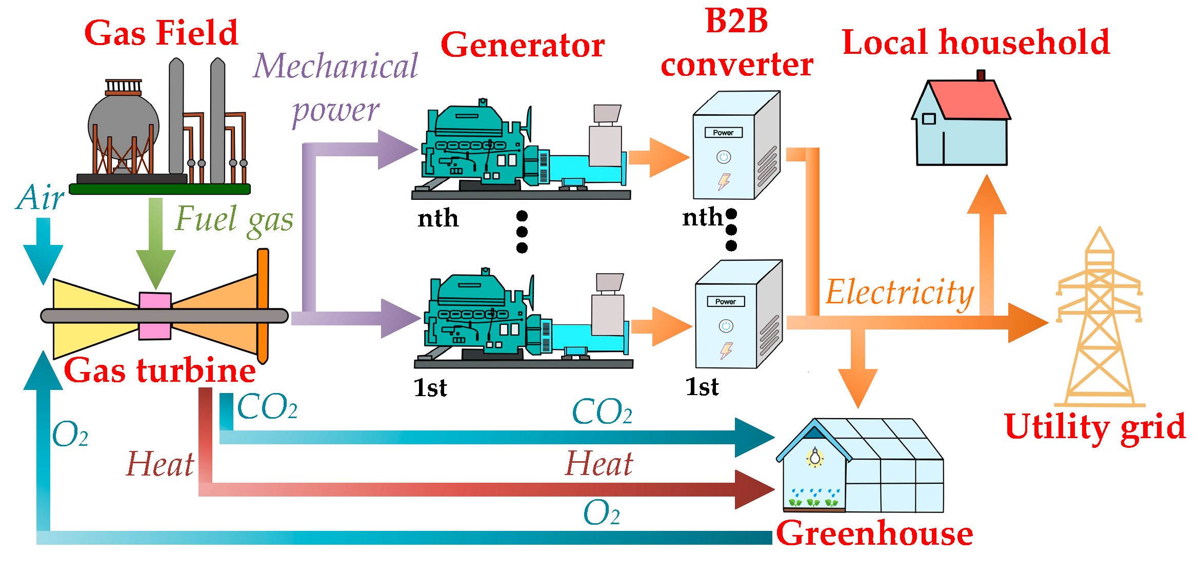
To overcome the problems resulting from the delivery of natural gas, a realistic solution is directly applying gas to produce electricity near gas fields and constructing on-site greenhouses, forming cogeneration facilities, as shown in Figure 1. In such a system, the extracted gas is combusted to drive the turbine, which serves as the mechanical input for the generators. Furthermore, the produced electricity is primarily exported to the public grid while a portion of the power can be allocated for greenhouses functioning and local households. Additionally, byproducts from the generation, carbon dioxide (CO2) and exhaust heat, respectively, can also fertilize plants and maintain the temperature of greenhouses. This innovation remarkably diminishes the environmental impacts related to gas utilization and opens the electricity market to gas producers.
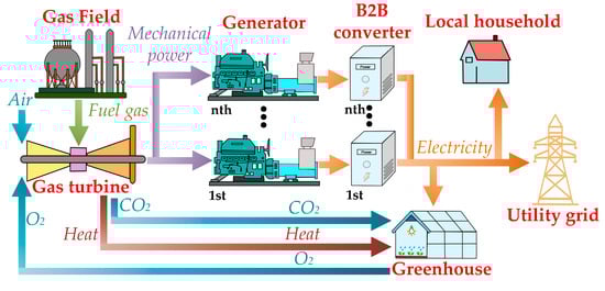
Figure 1.
System overview of proposed gas cogeneration plant.
Nevertheless, gas fields are typically far from the main load center, necessitating the use of long-distance power lines. When transmitting generated electricity to the grid, the line impedance causes a notable rise in voltage, which, in turn, leads to overvoltage issues at the gas fields and nearby communities. Simultaneously, the operation of some nonlinear appliances, such as grow lights in greenhouses and household air conditioners, introduces harmonic currents into the system, thereby deteriorating the power quality. These problems can potentially result in equipment damage and even power system outages, demanding urgent attention.
Being the conventional devices for enhancing power quality, the on-load tap changer (OLTC) [8,9], voltage regulator (VR) [10], and switched capacitor banks (CBs) [11,12] are widely used to maintain the steady-state node voltages within the permissible range while the passive filters are employed to eliminate the current harmonics [13,14]. However, these devices lack flexibility and operate discretely [15]. Thus, to achieve fast and adaptable voltage regulation and power quality improvement, the evolution of power electronic technology has brought the thyristor-type device: static var compensation (SVC) [16,17] and the voltage source converter (VSC)-type device: static synchronous compensator (STATCOM) [18,19] and active power filter (APF) [20,21]. Further, since the control of the thyristor itself produces harmonic distortions, SVCs cannot suppress the harmonics completely [22]. STATCOM and APF, on the other hand, have shown superior performance in stabilizing power quality and are broadly applied in power systems, where they accomplish flexible compensation for reactive power and harmonics by monitoring grid currents and voltages [23,24].
However, when dealing with the parallel generator setup in the power plants, STATCOM and APF have limited contributions to the system dynamics. The presence of multiple generators and their interactions with the utility grid make the dynamics more intricate. In the context of the current research, back-to-back (B2B) converters are predominantly employed within the realm of wind power generation [25,26,27,28]. However, there is still a relative lack of in-depth exploration regarding their application in gas power generation systems based on the synchronous generators (SG). Hence, this study is novel to incorporate the implementation of B2B converters to connect the synchronous generator to the power grid. Superior to the traditional approaches, such as STATCOM, SVC, and APF, the B2B converter not only mitigates the power quality issues but also refines the dynamics of a multi-generator system by decaying the low-frequency oscillations (LFO). Moreover, three control approaches for the B2B converter are presented, thereby further enhancing the practicality and comprehensiveness of this research. For each control strategy, the full-order state-space model is derived. Additionally, by analyzing the stability of the converter under different grid strengths [29], this research can offer guidance for selecting a proper control. Ultimately, this paper also explores the favorable influence of the B2B converter on power quality and system dynamics in detail.
The rest of the paper is organized as follows. The background is formulated in Section 2. The hardware structure and control principles of the converter are elucidated in Section 3. The enhancement in the power quality is exhibited in Section 4. The dynamics of the multi-generator system are discussed in Section 5. Further, small-signal analysis of the three control schemes is conducted in Section 6. Finally, the obtained results are evaluated in Section 7, and conclusions are summarized in Section 8.
2. Background
In this section, the structure and performance of an existing cogeneration power plant located at Gull Lake, Alberta are elaborated. As in the lumped model shown in Figure 2, the main feeder includes four nodes, and the electricity is provided by a 480 V/2.5 MVA gas turbine SG at Node 4. At the output terminal of the SG, a transformer is equipped to step up the output voltage from 480 V to 25 kV, and the dashed box indicates the proposed location for installing the B2B converter. It is worth noting, however, that the measurements of power quality presented below are undertaken without the integration of the B2B converter.
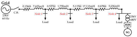
Figure 2.
Diagram of the system configuration.
Due to the presence of greenhouses and residential areas, nonlinear loads account for a certain portion of the total electrical demand. Unlike linear loads, the voltage–current relationship of nonlinear loads is not constant, introducing current distortion when connected to a power system. Using the grow light as an example, it behaves as a current-controlled voltage source, or a variable conductance [30,31]. Its conductance, G, can be described as (1), where i represents the lamp current, and A, B, C, and D denote the lamp model coefficients.
Table 1 shows the information regarding the load distribution and power quality measurements for the generator operating at different power ratings, 1 MVA or 2.5 MVA. As the requirements from the utility company, the upper limit for node voltages is 1.03 p.u., and the total harmonic distortions (THD) must be maintained under 5% [32,33]. From Table 1, it indicates that the power quality is deemed acceptable when the generated power is 1 MVA. However, as the injected power increased, the voltage at Node 4 surpassed the limit.

Table 1.
Load distribution and power quality measurement.
Furthermore, the intensified usage of HVAC (heating, ventilation, and air conditioning) systems by residents and grow lights inside greenhouses leads to a substantial rise in the nonlinear loads. Since these pieces of equipment are predominantly situated at Node 4, there is a considerable load increase at this location. Table 2 provides the measurement of power quality under this scenario, with the generator operating at 2.5 MVA, and the obtained results state that Node 4 suffers from both overvoltage and unacceptable THD.
Table 2.
Power quality measurement under increased nonlinear loads.
As a result, from the above tests, it can be inferred that a higher output of the generator and a greater proportion of nonlinear loads result in a more drastic deterioration in the power quality. Hence, to prevent the more severe power quality issues in systems with higher power ratings, it is essential to adopt measures that effectively handle these challenges. As depicted in Figure 2, this article focuses on the utilization of B2B converters to deliver continuous enhancement in power quality, and the following section delves into the hardware configuration of this setup and develops feasible controls.
3. System Configuration and Control Strategies Overview
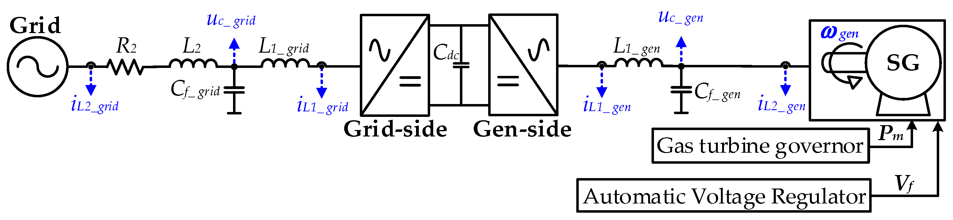
The structure of the gas generation is shown in Figure 3. In this system, the SG is interconnected to the grid through the B2B converter, where the line impedance is R2 and L2. A B2B converter comprises two VSCs connected in series through a DC link capacitor, Cdc. These VSCs are differentiated by their locations, with one being referred to as the grid-side VSC and the other as the generator-side VSC. To distinguish which side of VSC the variables belong to, subscripts ‘grid’ and ‘gen’ are used. On each side of the VSC, a typical three-level DC/AC converter is applied, with an LC filter (L1 and Cf) coupled at its output terminals. The filter inductor current is symbolized as iL1, and uc and iL2 denote the VSCs’ output voltage and current, respectively. For the SG operation, the mechanical input (Pm) is provided by the gas turbine, and the generator rotation speed (wgen) is regulated by the frequency droop or isochronous control adopted in the speed governor (GOV). Concurrently, the automatic voltage regulator (AVR) monitors the terminal voltage of the generator and adjusts the excitation system to produce appropriate field voltage (Vf), ensuring the SG maintains a stable output voltage. In this study, the IEEE ST1A model is utilized as the excitation system to regulate the SG’s field current [34].
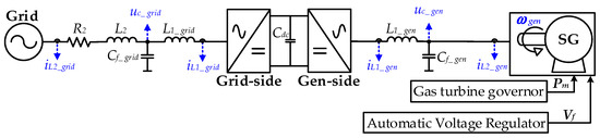
Figure 3.
Diagram of gas field generation with back-to-back converter.
Moreover, the converter control is realized in dq rotation frame, and they can be divided into grid-forming (GFM) control and grid-following (GFL) control. For GFL converters, they perform as controlled current sources, and the phase-locked loop (PLL) plays a critical role in synchronizing the converter with grids [35,36,37,38]. Additionally, the PLL computes the appropriate phase shift for the converter current control. The outer control loop determines the dq-axis current reference while current control is implemented in the inner loop to govern the injected current, and the voltage feedforward control is usually incorporated into the output of the current controller, enhancing the dynamic performance.
Compared to GFL, a GFM converter employes voltage-based control techniques, granting it the capability to operate not only in grid-connected condition but also in island mode. When encountering severe disturbances, such as short-circuit faults, GFM control greatly bolsters the robustness of the power system [39]. Additionally, during the grid-tie operation, the converter can accomplish the power exchange via controlling the voltage magnitude and angle at output terminals. Furthermore, the virtual synchronous generator (VSG) algorithm is commonly applied in GFM converters, enabling the achievement of grid synchronization through the swing equation [40,41]. Further, the output power of the converters is utilized to generate the phase and magnitude of the voltage reference through active power control (APC) and reactive power control (RPC), respectively. Then, the voltage control loop cascades with the current control, regulating the output voltage to follow the voltage reference. Finally, it is also worth noting that the inner current control loop of the GFM converter is the same as that of the GFL converter.
Table 3 and Table 4 present an extensive summary of control objectives for both generator-side and grid-side VSCs, along with their associated benefits. By varying the selection of control targets on both sides, a range of diverse control strategies for the B2B converter can be derived.
Table 3.
Overview of generator-side VSC control objectives and advantages.
Table 4.
Overview of grid-side VSC control objectives and advantages.
Evidently, the application context also imposes some constraints on the design of control strategies, such as addressing the overvoltage issues in the gas generation system, where the grid-side VSC must regulate the AC voltage magnitude at the point of common coupling (PCC). Based on the above discussion, three feasible strategies are listed in Table 5.
Table 5.
Control strategy overview.
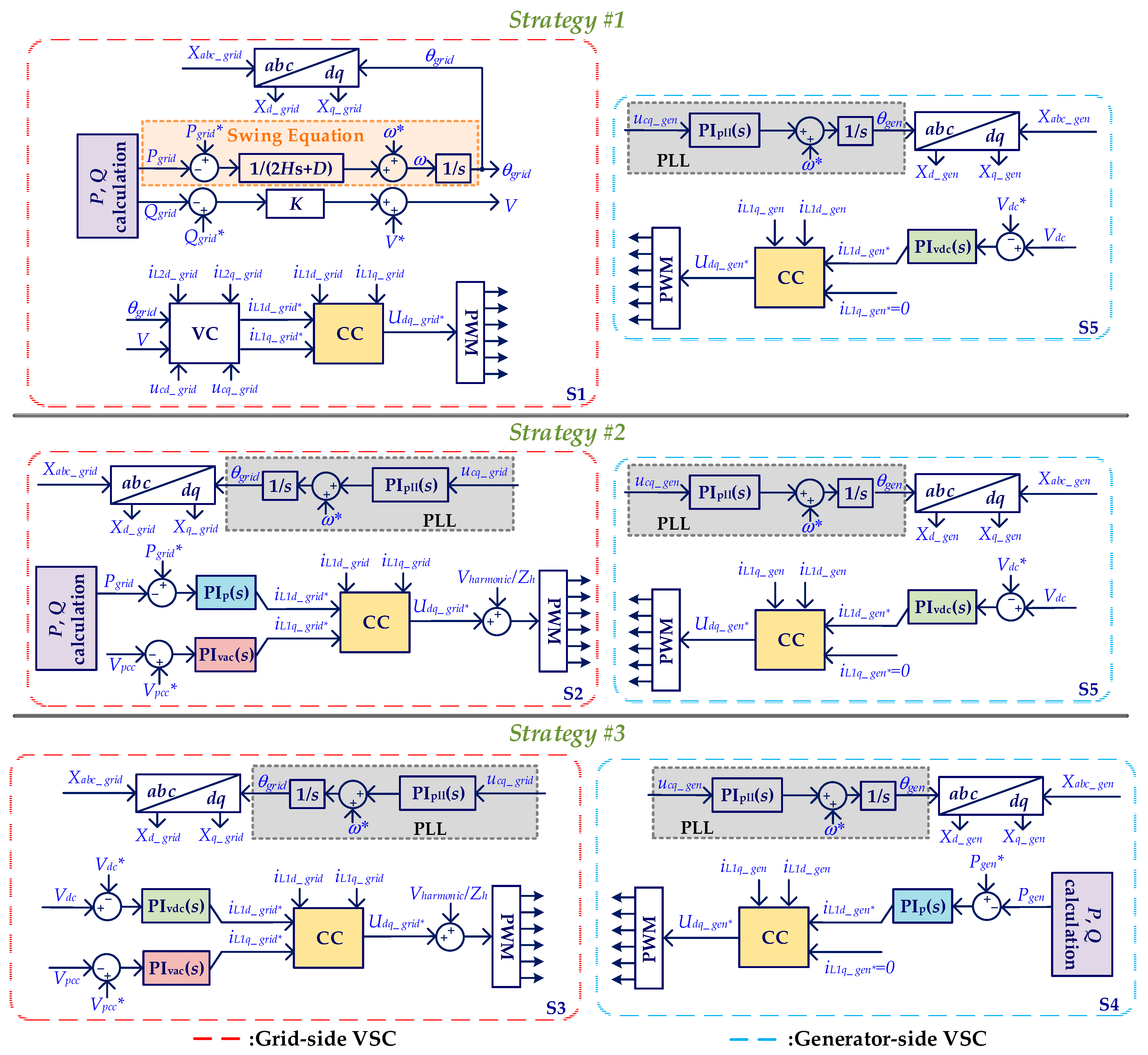
Figure 4 shows the control diagrams for both sides of VSCs, where ‘*’ indicates the reference values; variable ‘X’ represents the inductor current (iL1), output current (iL2), or output voltage (uc), and ‘VC’ or ‘CC’ stands for voltage or current control loop. Similar to Figure 3, subscripts ‘grid’ and ‘gen’ are used to identify if variables belong to either grid side or generator side, and the subscripts d and q denote the variable in respective axes. S1 shows the scheme of the GFM control, where the output active power (Pgrid) and reactive power (Qgrid) of the converter are used to generate the phase angle (θgrid) and voltage magnitude (V) of the voltage reference. Further, the orange highlighted portion expresses the swing equation used for the grid synchronization. Then, the voltage control loop (VC) employs the proportional-integral (PI) and feed-forward control to set the current reference. The inner current control loop (CC) precisely regulates the grid current based on the obtained reference, and the output of the CC is used to modulate the switching signals of the converter. Contrarily, S2-S5 belongs to GFL controls, where synchronization with the grid is achieved via the PLL. The principle of the PLL is illustrated within the gray highlighted area, where the outer loops employ the PI controllers to generate the reference of the dq-axis current. By regulating real power or DC voltage, the d-axis current reference (iL1d*) is determined. Additionally, the q-axis current reference (iL1q*) of the grid-side VSC is set by AC voltage control, while the generator-side VSC keeps it at zero. Then, these current references serve as the setpoints for grid current regulation within the CC. All hardware and controller parameters are given in Appendix A.
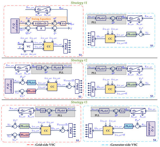
Figure 4.
Diagrams of grid-side and generator-side VSCs’ controls.
4. Power Quality Improvement
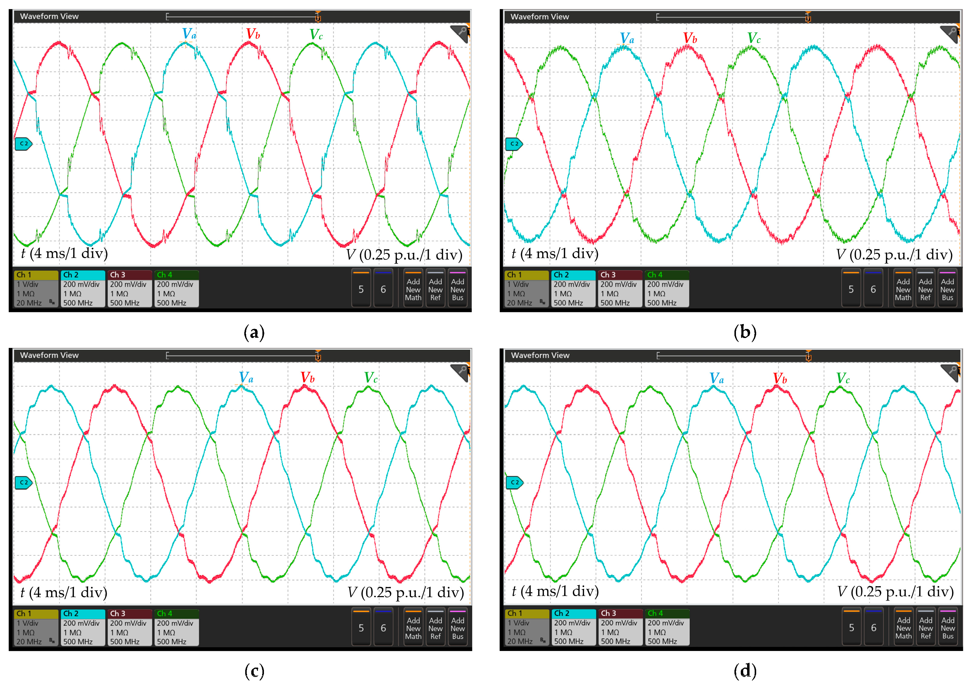
To demonstrate the enhancements in power quality brought about by the B2B converter, real-time simulations are conducted using the OPAL-RT platform. The setup details of this platform are provided in Figure A1. Recall Table 2 in Section 2: in the case of high-power generation and large portion of nonlinear loads, the voltage profile and THD of Node 4 exceed the permissible limits. Therefore, Figure 5 presents the voltage waveforms of Node 4 in both the presence and absence of the B2B converter, providing evidence of the improvement in power quality. According to the collected results, they demonstrate that the node voltage is less distorted and maintained approximately at 1 p.u. after the B2B converter is connected to the system, highlighting the converter’s effectiveness in enhancing power quality. Finally, Table 6 summarizes the performance of various control strategies.
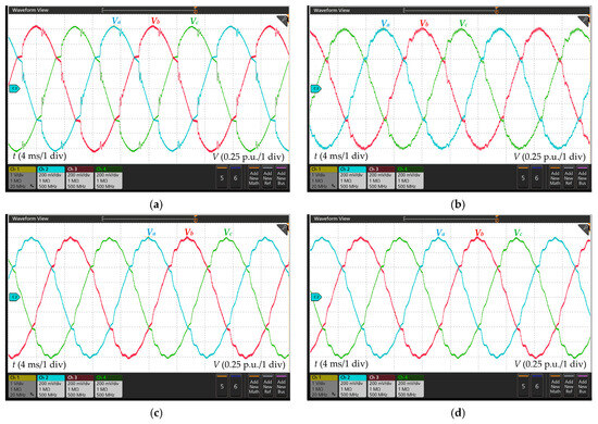
Figure 5.
Node 4 voltage waveforms. (a) Without the B2B converter; (b) strategy #1; (c) strategy #2; (d) strategy #3.
Table 6.
Power quality measurement at Node 4.
By comparing outputs with the scenario where the generator is directly connected to the grid, it can be found that the B2B converter can suppress the overvoltage by regulating the reactive power and alleviate the voltage distortion by compensating for harmonics. Consequently, the existing power quality issues can be effectively resolved, and the feasibility of the proposed power electronic solution has been verified. Additionally, the B2B converter also offers prospective benefits for multi-generator systems, and more details will be explored in the upcoming section.
5. The Enhancement of Multi-Generator System Dynamics
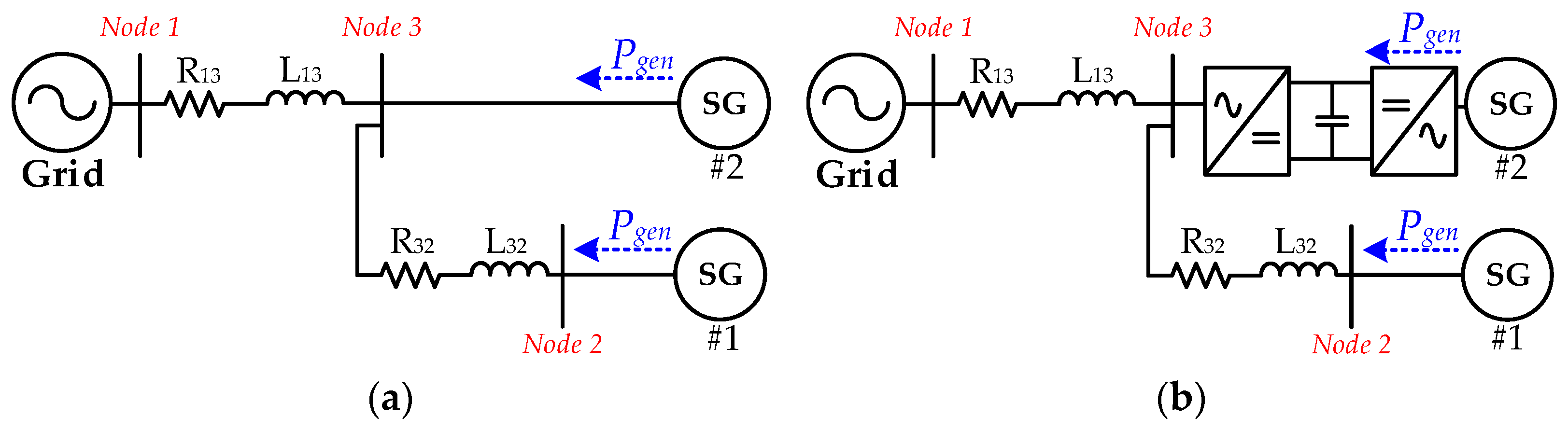
Because of the power constraints of a single generator, in gas power generation, it is highly practical to employ multiple generators operating in parallel. This configuration not only enlarges the total power output [58] but also provides redundancy and backup capabilities to handle potential faults or maintenance situations, thereby improving the system reliability. However, directly connecting multiple generators to the grid worsens the system dynamics, particularly when there are changes in the output power of the generators. Because this integration setup allows the generators to share a load, any fluctuation in one generator’s output, such as an increase or decrease in power, can lead to frequency variations within the grid. Based on the swing equation of generators, the power of the remaining generators will undergo low-frequency oscillations, and the risk posed by these oscillations is particularly pronounced for generators operating close to the full capacity and with large inertia since they are susceptible to triggering generator overload protection mechanisms. In extreme cases, these oscillations can escalate to the point of system instability. By employing B2B converters, generators can be decoupled from each other, effectively minimizing the LFO among them. To better explain the improvement in system dynamics brought about by the B2B converter, two dual-generator networks are established, as shown in Figure 6. The only variance between these two systems is the way SG #2 is connected to the utility grid.
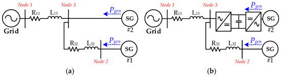
Figure 6.
Structure diagram of multi-generator system. (a) Both SGs are directly connected to the utility grid; (b) one of the SGs is connected to the utility grid through the B2B converter.
With the intention of elucidating the impact of the B2B converter on system dynamics, a quasi-stationary model in the dq rotating frame is employed. For the grid-connected converter, the quasi-stationary model is simplified from the full-order model by neglecting the dynamics of the inner current control loops. Generally, the control bandwidth of the inner loops is designed to be much higher than the outer control loops [59,60]. Hence, this simplification can still capture the frequency-power dynamics of the converter. Additionally, this type of quasi-stationary model has also been implemented to investigate the stability of DC link voltage control for GFL converters [61,62] and compare the dynamics of GFM converters under stand-alone and SG-connected operations in [63].
In the modelling of generators, the dynamics of SGs’ stator voltage, field windings, and excitation systems are incorporated into the conventional quasi-stationary model. This refinement improves the precision in characterizing the LFO present in SGs, and the performance of the enhanced model has been validated by comparing it with the SG’s full-order model [64].
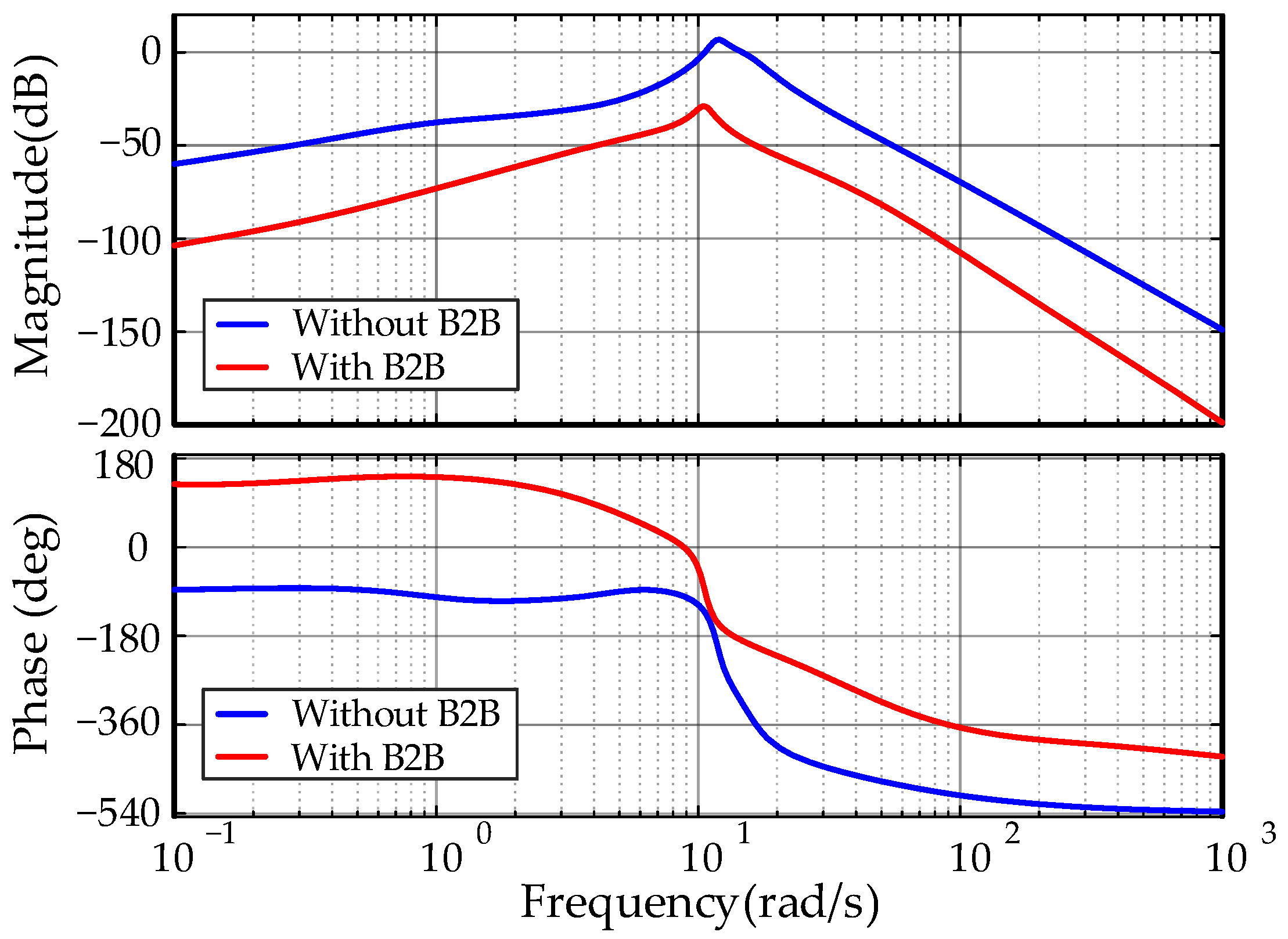
In Figure 7, the performance of both systems shown in Figure 6 is examined. The Bode plot highlights that the resonant peak experiences a significant reduction when SG #2 is integrated into the grid through the B2B converter, which suggests that the B2B converter has positive impacts on system dynamics.

Figure 7.
Bode plots of systems without and with the B2B converter.
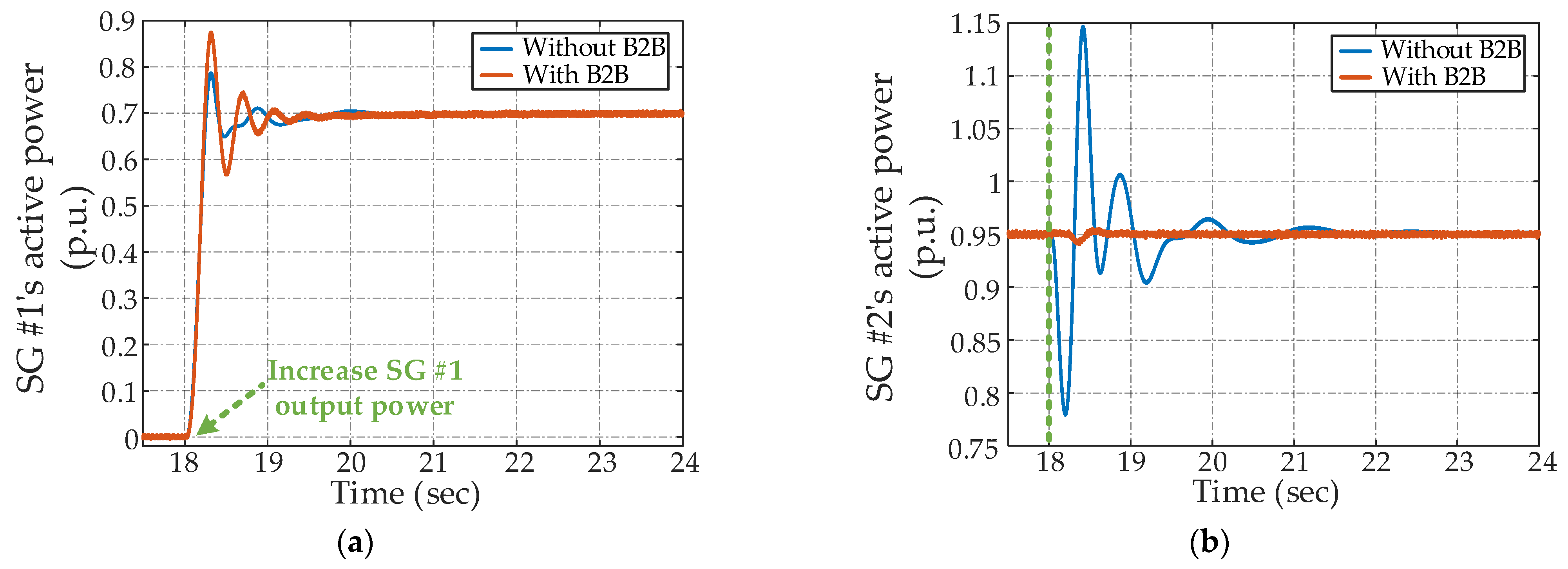
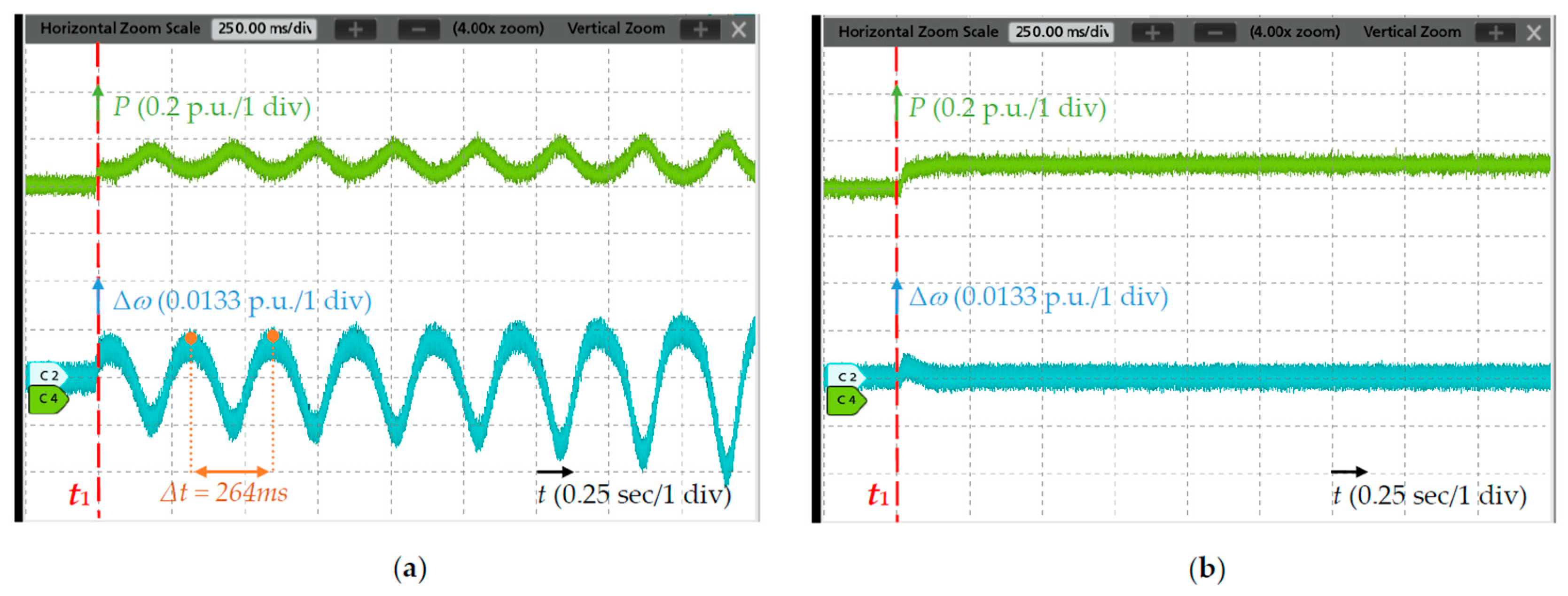
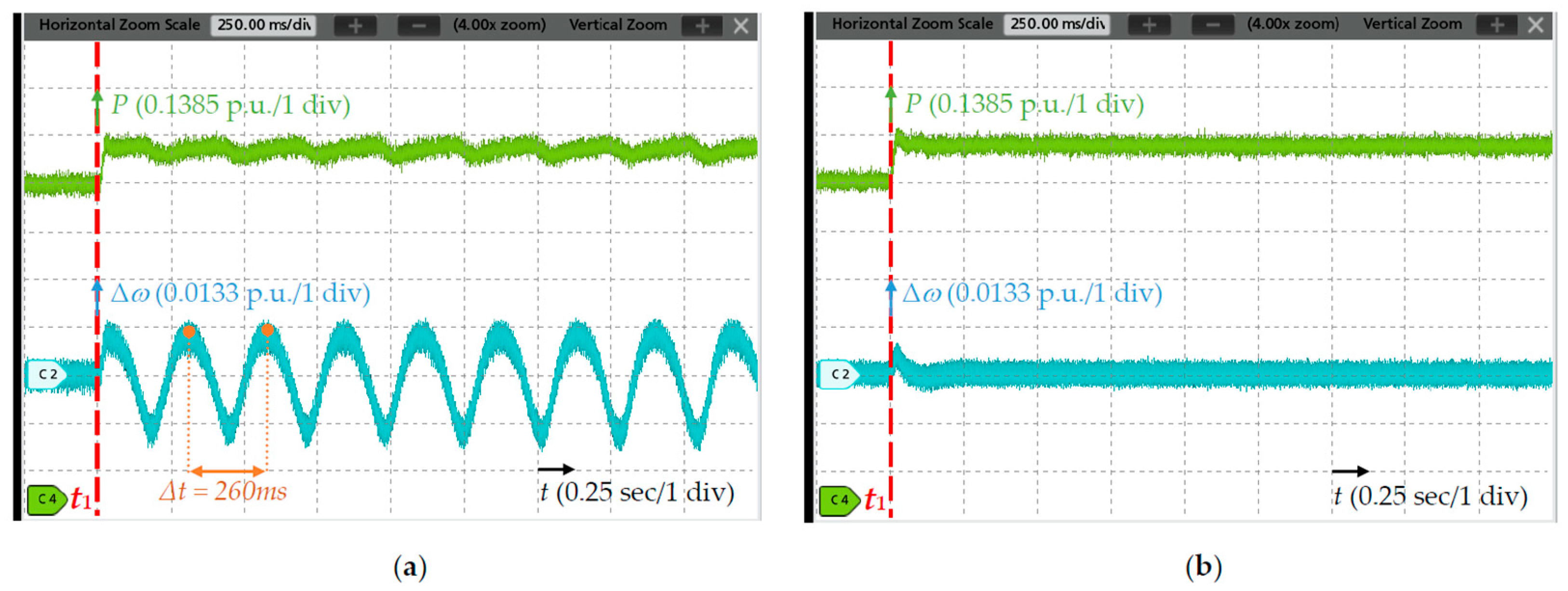
Meanwhile, real-time simulations are carried out for both system configurations, and the results are shown in Figure 8. During the simulations, a step change is applied in the output power of SG #1 at 18s, while the dynamic response of SG #2 is observed. The obtained results elaborate that, in the absence of the B2B converter, modifying the output power of SG #1 leads to the power oscillation of SG #2, resulting in an instantaneous output exceeding its rated capacity by approximately 15%. With the introduction of the B2B converter, however, the output power of SG #2 can remain within the power rating, and the dynamics of a multi-generator system can be ameliorated through damping the LFO. These findings not only validate the above theoretical analysis but also emphasize the effectiveness of the B2B converter in enhancing system dynamics.
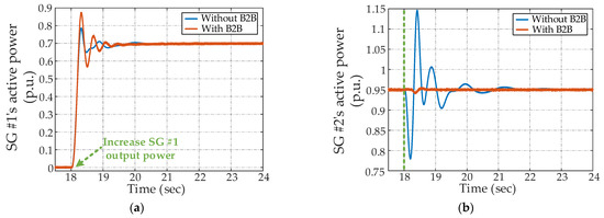
Figure 8.
Real-time simulation results. (a) Active power of SG #1; (b) active power of SG #2.
6. Converter Control Strategy Selection Guidance
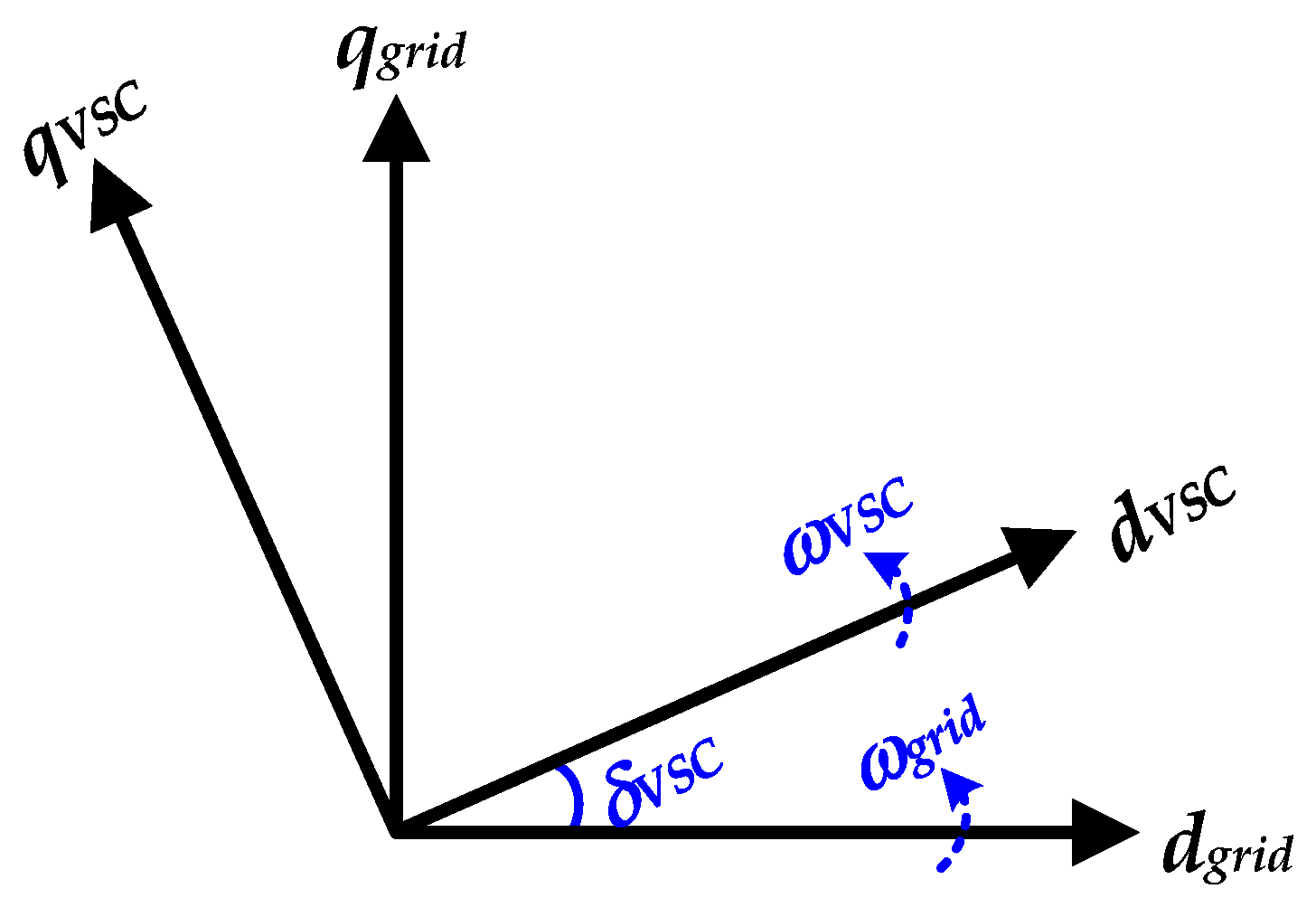
The analysis in previous sections illustrates that the B2B converter brings significant improvement in both the power quality and the dynamics of multi-generator systems. However, due to the distinct grid synchronization mechanisms between GFM and GFL converters, different control schemes encounter stability issues under varying grid strengths. Further, it is critical to consider the actual grid impedance when choosing the control strategies for the converter. To investigate the performance of grid-connected converters, the full-order state-space models for all control strategies are derived, and small-signal analysis is presented. Compared to the reduced-order model, full-order models can capture the system dynamics to the utmost [65], such as LCL circuit dynamics, PLL dynamics, outer control loops dynamics, and inner current controller dynamics. In particular, the line impedance exerts a substantial influence on the stability, apart from the converter controller parameters. Deriving the full-order models also guarantees a higher level of accuracy when analyzing the stability of converters. Moreover, consistent with the control diagrams outlined in Figure 4, all models are developed in the dq rotation frame, and variables are expressed in the per-unit form. The generator-side VSC is simplified based on its control objectives to either function as a constant voltage source or a constant current/power source. As shown in Figure 9, the power grid and VSCs possess their own rotation coordinates, characterized by the angular frequencies of wgrid and wVSC, respectively.

Figure 9.
dq rotating reference frames.
To integrate the VSC into the system model while considering the dynamics of the entire system, it is necessary to transform the dq-axis output current of the VSC (iL2_d_VSC or iL2_q_VSC) into the grid’s rotation frame (dqgrid). Further, the input variable, PCC voltages (VPCC_d_grid or VPCC_q_grid), should be converted into the VSC’s frame. Since the grid’s frame serves as the common reference frame and considering a phase angle difference of δVSC between two rotation frames, the transformation between these two dq frames can be carried out by (2) and (3).
The state-space model for the entire system can be described as (4), where xsystem and usystem, respectively, represent the state vector and input vector, and Asystem and Bsystem separately indicate the state matrix and input matrix. Details of matrices are provided in Appendix B.
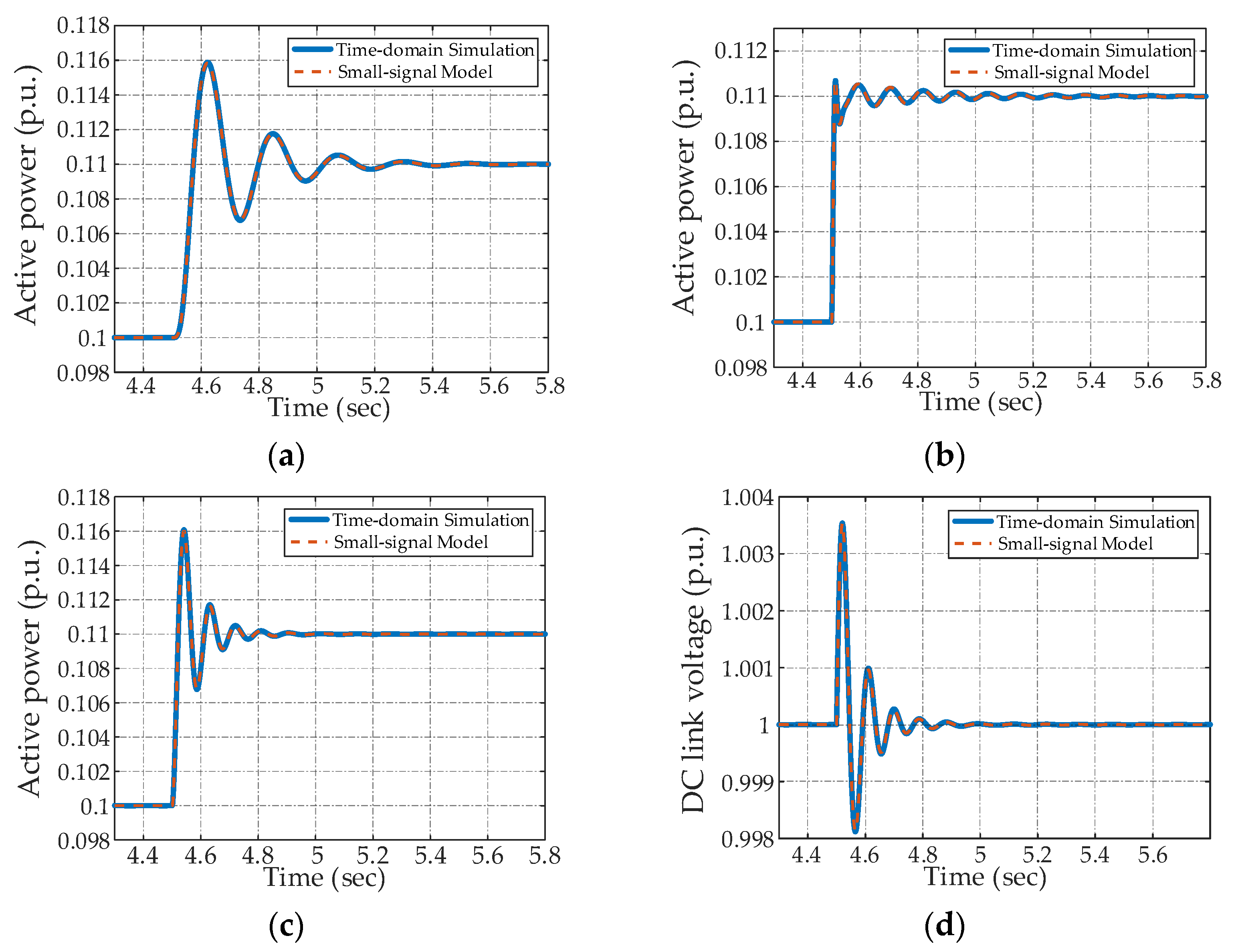
After developing the state-space models, the accuracy validation is conducted by comparing them with the time-domain simulations. As depicted in Figure 10, a step change in active power reference from 0.1 to 0.11 p.u. is applied at t = 4.5 s. The results clearly demonstrate that the responses of state-space models are aligned with those from simulations in the time domain thereby confirming the accuracy of the derived models.
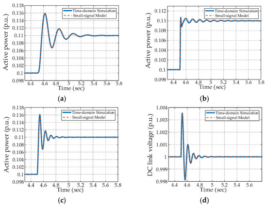
Figure 10.
Model verification. (a) Active power of the VSC in strategy #1; (b) active power of the VSC in strategy #2; (c) active power of the VSC in strategy #3; (d) DC link voltage in strategy #3.
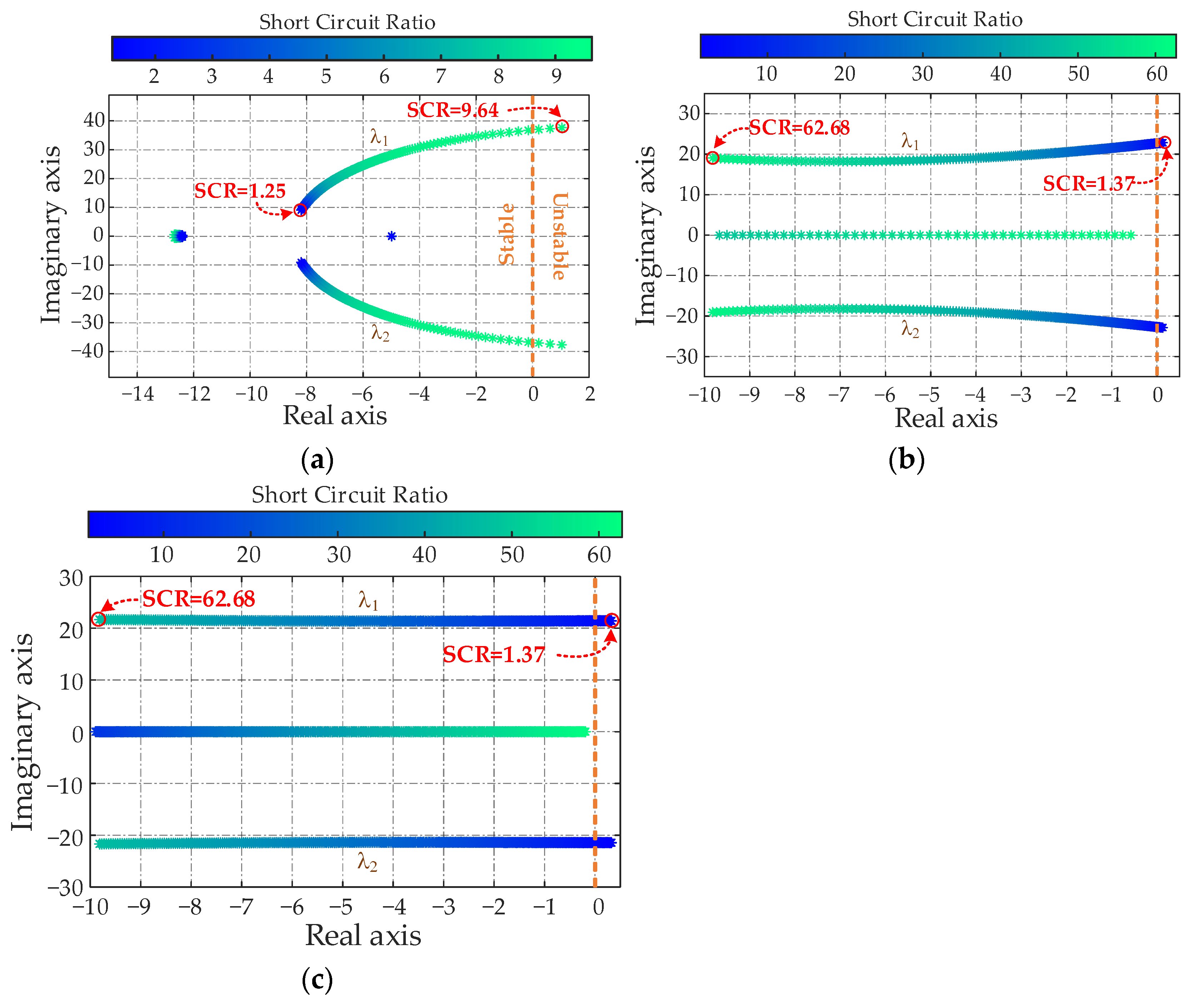
According to the parameters in state matrices, the eigenvalue trajectories are plotted in Figure 11 to compare the stability of three controls under diverse short circuit ratios (SCR) while maintaining all controller parameters unchanged. It can be found that, when the grid-side VSC is under the GFM control (strategy #1), the conjugated eigenvalues (λ1 and λ2) move toward the right-half plane with a stronger grid. Additionally, further increasing SCR to 9.6 causes λ1 and λ2 to reach the unstable region. In contrast, λ1 and λ2 of the GFL-controlled VSCs (strategies #2 and #3) shift to the right-half plane when the grid is weaker, and the systems eventually lose stability when the SCR reaches 1.37. Ultimately, the eigenvalue analysis reveals that GFM and GFL controls exhibit opposite stability characteristics under varying grid strengths, and the GFM control is more suitable for weak grids.
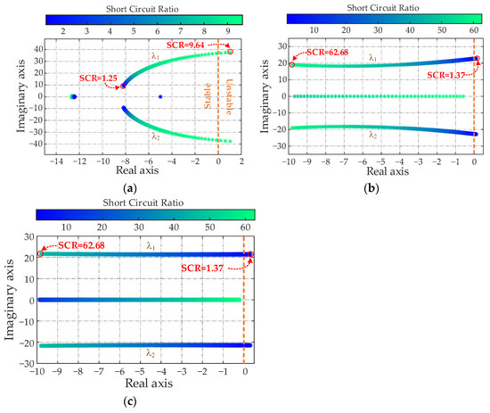
Figure 11.
Root-loci plots under varying SCRs. (a) Strategy #1; (b) strategy #2; (c) strategy #3.
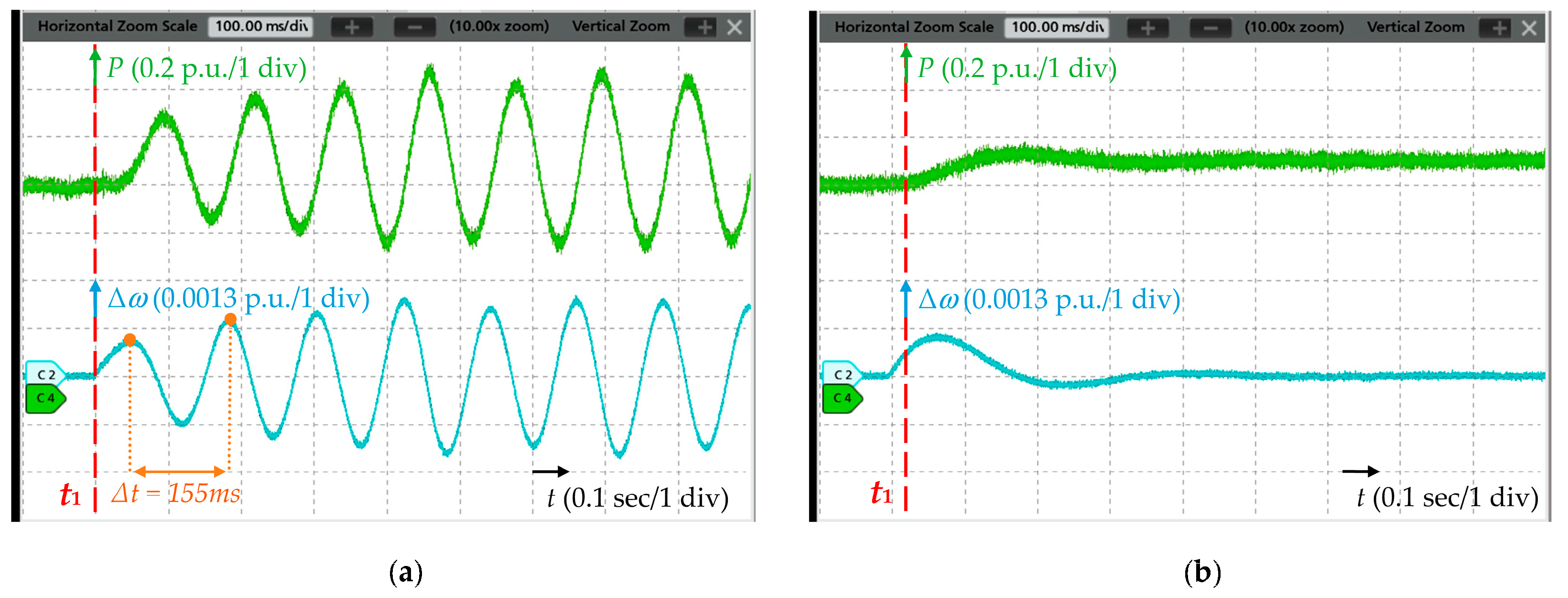
To verify the above eigenvalue analysis, real-time simulations are carried out, and the parameters are identical to those specified in Section 3. For each strategy, two testing points are examined. One is at the grid strength during an unstable state, while the other is at the adjusted SCR to restore the system stability. Figure 12, Figure 13 and Figure 14 demonstrate the active power output and frequency response of three control schemes following a disturbance at different SCRs. Simulation cases 1 and 2 are conducted to validate the stability analysis of the GFM converter (strategy #1), and the corresponding SCRs are 9.64 and 2.95, respectively. Additionally, as shown in Figure 12, the output power reference is changed from 0.9 p.u. to 1 p.u. at t1. In case 1, the active power output and frequency experience noticeable oscillations at the frequency of approximately 6.45 Hz, which is consistent with the analysis. After decreasing the grid strength to SCR = 2.95, the oscillations are damped, and the system reaches a new steady-state operating point in case 2, indicating that the GFM converter exhibits better stability when weakening the grid strength.
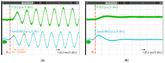
Figure 12.
Step response of strategy #1. (a) Case 1 (SCR = 9.64); (b) case 2 (SCR = 2.95).
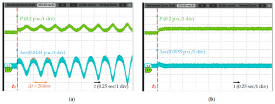
Figure 13.
Step response of strategy #2. (a) Case 3 (SCR = 1.37); (b) case 4 (SCR = 2.24).
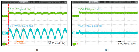
Figure 14.
Step response of strategy #3. (a) Case 5 (SCR = 1.37); (b) case 6 (SCR = 2.24).
Cases 3, 4, 5, and 6 are used to verify the stability of the GFL converter (strategy #2 and strategy #3), with the SCRs being 1.37 and 2.24. As presented in Figure 13 and Figure 14, the same disturbance is applied at t1. In cases 3 and 5, the active power and frequency undergo diverging oscillations, with a similar frequency of about 3.78 Hz. After increasing the grid strength to SCR = 2.24, the systems can converge to a new operating point in cases 4 and 6. Therefore, these simulation results illustrate that the GFL control has better stability under stiffer grids.
These simulation results not only provide an intuitive illustration of the impact of grid strength on the stability of GFM and GFL converters but also corroborate the root-loci plots shown in Figure 11. According to the collected results, Table 7 summarizes the stability boundaries for three studied control schemes. Referring to the application context of gas generation, the geographical locations of gas fields are usually far from the grid, resulting in converters being connected to weak grids. It can be concluded that strategy #1 is the optimal choice for gas field generation, considering its distant location.
Table 7.
Stability under different grid strengths.
7. Discussion
The main barrier in the current cogeneration system is the power quality issues, including voltage profile and harmonics. Prior to integrating the B2B converter into the system, the gas turbine generator operates at unity power factor, causing the voltage at Node 4 to exceed the permissible range and contain considerable portions of distortions. Through the compensation offered by the B2B converter for harmonics and reactive power, the THD of the node voltage can be improved from 6.84% to 3.33% (lower than 5%). Meanwhile, the voltage magnitude can remain around 1 p.u., which indicates the overvoltage is effectively suppressed. Due to the responsibility of B2B converters in transmitting the generated active power to the grid and compensating for the reactive power to mitigate the overvoltage at PCC, the capacity selection of the converter becomes significant in the design of such converter-interfaced generation systems. In this research, the maximum active power output is 2.5 MW, with a corresponding reactive power compensation requirement of 0.52 MVar, resulting in a power factor of 0.97. Furthermore, the minimum allowable capacity of the VSC is 2.55 MVA. To incorporate redundancy in the design and ensure enough margin for contingencies, a rated power of 3 MVA is chosen for the converter in this study. In terms of system stability, all three controls can secure the stable operation of the converter within the range of 1.37 < SCR < 9.64. If the grid falls below this range in strength, GFM control (strategy #1) becomes the only feasible option for regulating the B2B converter. Finally, when the grid’s SCR surpasses 9.64, either GFL control (strategies #2 or #3) can be utilized.
8. Conclusions
In this article, the power quality issues in gas cogeneration systems have been discussed. Due to a long-distance transmission line, high-power injection to the grid causes the voltage magnitude at the remote node to reach 1.055 p.u., which exceeds the acceptable limit by 2.5%. Additionally, a substantial proportion of nonlinear loads in the system results in a notable presence of harmonic components in the node voltage, with the THD measured at 6.84%. By incorporating the B2B converter, the power quality of the above system can be significantly enhanced by compensating for the reactive power and harmonics, resulting in both voltage profile and THD falling within the permissible range. Furthermore, under the scenario of multiple generators operating in parallel, the B2B converter can optimize the dynamic response through attenuating the LFO that exists among the generators. In terms of the B2B converter control, this article presents three viable strategies that are tailored to the requirements of the gas field generation. These control options can be categorized into grid-forming and grid-following, characterizing distinct stability under different grid strengths. Therefore, when designing the converter-interface generation systems, it is essential to take the grid conditions into account. To analyze the impact of grid impedance on control stability, this paper developed the full-order state-space models for the grid-side VSCs. Through the eigenvalue analysis, the grid-forming control (strategy #1) has been evidenced to demonstrate greater stability under weak grids (SCR ≤ 1.37). On the other hand, the grid-following controls (strategies #2 and #3) have been found to be more suitable for a stiff power grid (SCR ≥ 9.64). Moreover, the stability boundaries of all controls are obtained, providing valuable insights for selecting control schemes. Finally, considering the actual grid impedance of the gas generation system, the conclusion can be drawn that strategy #1 is the optimal choice. Additionally, real-time simulations highlight the benefits of the B2B converter and validate the accuracy of the analysis.
Author Contributions
Conceptualization, W.L., R.L. and Y.L.; methodology, W.L. and R.L.; software, W.L.; validation, W.L.; formal analysis, W.L.; investigation, W.L., R.L. and Y.L.; resources, W.L., R.L. and Y.L.; data curation, W.L.; writing—original draft preparation, W.L.; writing—review and editing, W.L., R.L. and Y.L.; visualization, W.L.; supervision, Y.L.; project administration, W.L.; funding acquisition, Y.L. All authors have read and agreed to the published version of the manuscript.
Funding
This research was funded by Alberta Innovates.
Data Availability Statement
Not applicable.
Conflicts of Interest
The authors declare no conflict of interest.
Appendix A
The real-time simulation platform setup is shown in Figure A1.
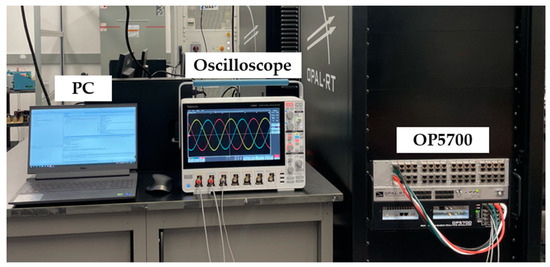
Figure A1.
OPAL-RT platform setup.
Figure A1.
OPAL-RT platform setup.

Table A1.
List of symbols in control diagram.
Table A1.
List of symbols in control diagram.
| Symbol | Description |
|---|---|
| Pgrid*, Qgrid* | Rated grid-side active and reactive power |
| Pgrid, Qgrid | Measured grid-side active and reactive power |
| Vdc*, Vdc | Rated and measured DC link voltage |
| Vpcc*, Vpcc | Rated and measured voltage at point of common coupling |
| Pgen*, Pgen | Rated and measured generator-side active power |
| H | Inertia constant |
| D | Damping constant |
| K | Voltage droop coefficient |
| w*, w | Rated and measured frequency |
| θgrid, θgen | Grid-side and generator-side phase angles |
| V*, V | Rated voltage and generated voltage reference |
| iL2d_grid, iL2q_grid | Measured grid-side output current in dq |
| ucd_grid, ucq_grid | Measured grid-side output voltage in dq |
| iL1d_grid*, iL1q_grid* | Reference of grid-side inductor current in dq |
| iL1d_gen*, iL1q_gen* | Reference of generator-side inductor current in dq |
| iL1d_grid, iL1q_grid | Measured grid-side inductor current in dq |
| iL1d_gen, iL1q_gen | Measured generator-side inductor current in dq |
| Vharmonic | Harmonic voltage |
| Zh | Harmonic impedance |
The parameters of the gas generation system are given in Table A2, and the controller parameters for the B2B converter under three control strategies are provided in Table A3, Table A4 and Table A5.
Table A2.
Generation system parameters.
Table A2.
Generation system parameters.
| Symbol | Description | Value |
|---|---|---|
| Utility Grid | ||
| Vgrid_H | Higher-side line voltage (RMS) | 25 kV |
| Vgrid_L | Lower-side line voltage (RMS) | 480 V |
| fgrid | Grid frequency | 60 Hz |
| Synchronous Generator | ||
| Vgen | Terminal line voltage (RMS) | 480 V |
| Sn | Rated power | 2.5 MVA |
| fn | Rated frequency | 60 Hz |
| Hgen | Inertia constant | 1.4 s |
| Xd, Xd’, Xd’’, Xq, Xq’’ | dq-axis synchronous reactance | 2.4, 0.2, 0.15, 1.77, 0.26 p.u. |
| Tdo’, Tdo’’, Tqo’’ | dq-axis open-circuit time constant | 4.48, 0.07, 0.1 s |
| kGOV | Governor droop coefficient | 16.7 |
| TACT | Actuator time constant | 0.09 s |
| B2B Converter | ||
| Sn | Rated capacity | 3 MVA |
| fn | Nominal frequency | 60 Hz |
| L1, Cf | Filter inductance and capacitance | 0.1 mH, 0.57 mF |
| fsw | Switching frequency | 4 kHz |
| Vdc* | Nominal DC link voltage | 1300 V |
| Cdc | DC link capacitance | 0.095 F |
Table A3.
Strategy #1 controller parameters.
Table A3.
Strategy #1 controller parameters.
| Symbol | Description | Value |
|---|---|---|
| Grid-side VSC Controller | ||
| HVSG | Inertia constant | 1.5 s |
| DVSG | Damping constant | 50 |
| KVSG | V-Q coefficient | 0.05 |
| kp,VC, ki,VC | Voltage control loop | 2, 10 |
| kp,CC, ki,CC | Current control loop | 0.8, 10 |
| TLPF | Low-pass filter time constant | 0.002s |
| Generator-side VSC Controller | ||
| kp,pll, ki,pll | Phase-locked loop | 60, 1400 |
| kp,VDC, ki,VDC | DC link voltage control loop | 4, 200 |
| kp,CC, ki,CC | Current control loop | 0.5, 10 |
Table A4.
Strategy #2 controller parameters.
Table A4.
Strategy #2 controller parameters.
| Symbol | Description | Value |
|---|---|---|
| Grid-side VSC Controller | ||
| kp,pll, ki,pll | Phase-locked loop | 60, 1400 |
| kp,p, ki,p | Real power controller | 0.4, 40 |
| kp,VAC, ki,VAC | AC voltage controller | 0.2, 20 |
| kp,CC, ki,CC | Current control loop | 0.5, 10 |
| TLPF | Low-pass filter time constant | 0.002 s |
| Generator-side VSC Controller | ||
| kp,pll, ki,pll | Phase-locked loop | 60, 1400 |
| kp,VDC, ki,VDC | DC link voltage control loop | 4, 200 |
| kp,CC, ki,CC | Current control loop | 0.5, 10 |
Table A5.
Strategy #3 controller parameters.
Table A5.
Strategy #3 controller parameters.
| Symbol | Description | Value |
|---|---|---|
| Grid-side VSC Controller | ||
| kp,pll, ki,pll | Phase-locked loop | 60, 1400 |
| kp,VDC, ki,VDC | DC link voltage control loop | 4, 200 |
| kp,VAC, ki,VAC | AC voltage controller | 0.4, 20 |
| kp,CC, ki,CC | Current control loop | 0.5, 10 |
| Generator-side VSC Controller | ||
| kp,pll, ki,pll | Phase-locked loop | 60, 1400 |
| kp,p, ki,p | Real power controller | 0.4 40 |
| kp,CC, ki,CC | Current control loop | 0.5, 10 |
| TLPF | Low-pass filter time constant | 0.002s |
Appendix B
This section provides the matrices of state-space models for three control strategies, where the variables included in the state and input vectors are listed beneath each state-space equation, and prefix Δ indicates small-signal perturbations.
The overall state-space model of control strategy #1 is expressed in (A1), which describes the states of LCL filter (xLCL), VSG control (xVSG), output power calculations (xCal_S1), voltage controller (xVC), and inner current control loop (xCC_S1). Additionally, the models for each subsystem are provided in (A2)–(A6).
The state model of LCL filter is expressed as (A2), where iL1d and iL1q denote the inductor current in dq; ucd and ucq indicate the output voltage in dq; iL2d and iL2q represent the output current in dq; θ is the phase angle; and uid and uiq symbolize the converter terminal voltage in dq. It is worth highlighting that all three control strategies share an identical state model for the LCL filter.
The state model of the VSG control loop is expressed as (A3), where w indicates the output frequency, P denotes the output active power, and Pref represents the rated active power.
The state model of the power calculation is expressed as (A4), where Q indicates the output reactive power.
The state models of the voltage control loop and inner current loop are expressed as (A5) and (A6), respectively, where φud and φuq indicate the intermedium variables of the voltage loop in dq, and φid and φiq denote the intermedium variables of the inner current loop in dq.
The overall state-space model of control strategy #2 is expressed in (A7), which describes the states of LCL filter (xLCL), phase-locked loop (xPLL), outer control loop (xOutter(P,VAC)), output power calculations (xCal_S2), and inner current control loop (xCC_S2). Moreover, the models for each subsystem are provided in (A2) and (A8)–(A11).
The state model of the PLL is expressed as (A8), where ucq indicates the output voltage in q-axis, φpll represents the intermedium variables of the PLL, and θ denotes the phase angle. Additionally, control strategy #3 utilizes the same state model for the PLL.
The state model of the active power and PCC voltage control is expressed as (A9), where ucd and ucq indicate the output voltage in dq; φp and φac represent the intermedium variables of the active power and PCC voltage control loops, respectively; P denotes the output active power; and Pref is the rated active power.
The state model of the power calculation is expressed as (A10), where iL2d and iL2q represent the output current in dq.
The state models of the inner current loop are expressed as (A11), where φid and φiq denote the intermedium variables of the inner current loop in dq, uid and uiq symbolize the converter terminal voltage in dq, and iL1d and iL1q indicate the inductor current in dq.
The overall state-space model of control strategy #3 is expressed in (A12), which describes the states of LCL filter (xLCL), phase-locked loop (xPLL), outer control loop (xOutter(VDC,VAC)), DC link capacitor (xCap), and inner current control loop (xCC_S3). The models for each subsystem are also provided, which are shown in (A2), (A8), and (A13)–(A15).
The state model of the DC link voltage and PCC voltage control is expressed as (A13), where ucd and ucq indicate the output voltage in dq; φdc and φac represent the intermedium variables of the DC link voltage and PCC voltage control loops, respectively; and Vdc denotes the DC link voltage.
The state model of the DC capacitor is expressed as (A14), where iL2d and iL2q represent the output current in dq, and idc_gen indicates the DC current through the generator-side VSC.
The state models of the inner current loop are expressed as (A15), where φid and φiq denote the intermedium variables of the inner current loop in dq, uid and uiq represent the converter terminal voltage in dq, and iL1d and iL1q indicate the inductor current in dq.
References
- Prisyazhniuk, V.A. Alternative Trends in Development of Thermal Power Plants. Appl. Therm. Eng. 2008, 28, 190–194. [Google Scholar] [CrossRef]
- Harfoot, M.B.J.; Tittensor, D.P.; Knight, S.; Arnell, A.P.; Blyth, S.; Brooks, S.; Butchart, S.H.M.; Hutton, J.; Jones, M.I.; Kapos, V.; et al. Present and Future Biodiversity Risks from Fossil Fuel Exploitation. Conserv. Lett. 2018, 11, e12448. [Google Scholar] [CrossRef]
- Ilyushin, Y.V. Development of a Process Control System for the Production of High-Paraffin Oil. Energies 2022, 15, 6462. [Google Scholar] [CrossRef]
- Marinina, O.; Nechitailo, A.; Stroykov, G.; Tsvetkova, A.; Reshneva, E.; Turovskaya, L. Technical and Economic Assessment of Energy Efficiency of Electrification of Hydrocarbon Production Facilities in Underdeveloped Areas. Sustainability 2023, 15, 9614. [Google Scholar] [CrossRef]
- Fekry, H.M.; Eldesouky, A.A.; Kassem, A.M.; Abdelaziz, A.Y. Power Management Strategy Based on Adaptive Neuro Fuzzy Inference System for AC Microgrid. IEEE Access 2020, 8, 192087–192100. [Google Scholar] [CrossRef]
- Statistical Review of World Energy 2022. 2022. Available online: https://www.bp.com/content/dam/bp/business-sites/en/global/corporate/pdfs/energy-economics/statistical-review/bp-stats-review-2022-full-report.pdf (accessed on 1 August 2023).
- Cai, H.; Burnham, A.; Chen, R.; Wang, M. Wells to Wheels: Environmental Implications of Natural Gas as a Transportation Fuel. Energy Policy 2017, 109, 565–578. [Google Scholar] [CrossRef]
- Muttaqi, K.M.; Le, A.D.T.; Negnevitsky, M.; Ledwich, G. A Coordinated Voltage Control Approach for Coordination of OLTC, Voltage Regulator, and DG to Regulate Voltage in a Distribution Feeder. IEEE Trans. Ind. Applicat. 2015, 51, 1239–1248. [Google Scholar] [CrossRef]
- Le, A.D.T.; Muttaqi, K.M.; Negnevitsky, M.; Ledwich, G. Response Coordination of Distributed Generation and Tap Changers for Voltage Support. In Proceedings of the 2007 Australasian Universities Power Engineering Conference, Perth, Australia, 9–12 December 2007; pp. 1–7. [Google Scholar]
- Agalgaonkar, Y.P.; Pal, B.C.; Jabr, R.A. Distribution Voltage Control Considering the Impact of PV Generation on Tap Changers and Autonomous Regulators. IEEE Trans. Power Syst. 2014, 29, 182–192. [Google Scholar] [CrossRef]
- Brady, P.; Dai, C.; Baghzouz, Y. Need to Revise Switched Capacitor Controls on Feeders with Distributed Generation. In Proceedings of the 2003 IEEE PES Transmission and Distribution Conference and Exposition (IEEE Cat. No.03CH37495), Dallas, TX, USA, 7–12 September 2003; pp. 590–594. [Google Scholar]
- Viawan, F.A.; Karlsson, D. Voltage and Reactive Power Control in Systems With Synchronous Machine-Based Distributed Generation. IEEE Trans. Power Deliv. 2008, 23, 1079–1087. [Google Scholar] [CrossRef]
- Hamadi, A.; Rahmani, S.; Al-Haddad, K. A Hybrid Passive Filter Configuration for VAR Control and Harmonic Compensation. IEEE Trans. Ind. Electron. 2010, 57, 2419–2434. [Google Scholar] [CrossRef]
- Beres, R.N.; Wang, X.; Liserre, M.; Blaabjerg, F.; Bak, C.L. A Review of Passive Power Filters for Three-Phase Grid-Connected Voltage-Source Converters. IEEE J. Emerg. Sel. Top. Power Electron. 2016, 4, 54–69. [Google Scholar] [CrossRef]
- Li, Y.R.; Nejabatkhah, F.; Tian, H. Smart Hybrid AC/DC Microgrids: Power Management, Energy Management, and Power Quality Control, 1st ed.; Wiley: Hoboken, NJ, USA, 2022; ISBN 978-1-119-59837-4. [Google Scholar]
- Daratha, N.; Das, B.; Sharma, J. Coordination Between OLTC and SVC for Voltage Regulation in Unbalanced Distribution System Distributed Generation. IEEE Trans. Power Syst. 2014, 29, 289–299. [Google Scholar] [CrossRef]
- Tokiwa, A.; Yamada, H.; Tanaka, T.; Watanabe, M.; Shirai, M.; Teranishi, Y. New Hybrid Static VAR Compensator with Series Active Filter. Energies 2017, 10, 1617. [Google Scholar] [CrossRef]
- Sirjani, R.; Rezaee Jordehi, A. Optimal Placement and Sizing of Distribution Static Compensator (D-STATCOM) in Electric Distribution Networks: A Review. Renew. Sustain. Energy Rev. 2017, 77, 688–694. [Google Scholar] [CrossRef]
- Jiao, W.; Chen, J.; Wu, Q.; Li, C.; Zhou, B.; Huang, S. Distributed Coordinated Voltage Control for Distribution Networks With DG and OLTC Based on MPC and Gradient Projection. IEEE Trans. Power Syst. 2022, 37, 680–690. [Google Scholar] [CrossRef]
- Shyu, K.-K.; Yang, M.-J.; Chen, Y.-M.; Lin, Y.-F. Model Reference Adaptive Control Design for a Shunt Active Power Filter System. In Proceedings of the IECON 2006—32nd Annual Conference on IEEE Industrial Electronics, Paris, France, 6–10 November 2006; pp. 73–78. [Google Scholar]
- Akagi, H.; Fujita, H.; Wada, K. A Shunt Active Filter Based on Voltage Detection for Harmonic Termination of a Radial Power Distribution Line. IEEE Trans. Ind. Applicat. 1999, 35, 638–645. [Google Scholar] [CrossRef]
- Lv, Z.; Luo, A.; Zhou, K.; Jiang, W.; Guo, L.; Shen, Y. Research of Intellective High Quality Inverter-Based Distributed Power Supply System Collocating SVC. In Proceedings of the The 2nd International Symposium on Power Electronics for Distributed Generation Systems, Hefei, China, 16–18 June 2010; pp. 846–851. [Google Scholar]
- Arsoy, A.B.; Liu, Y.; Ribeiro, P.F.; Wang, F. Statcom- SMES. IEEE Ind. Appl. Mag. 2003, 9, 21–28. [Google Scholar] [CrossRef]
- Bhattacharya, A.; Chakraborty, C.; Bhattacharya, S. Shunt Compensation. EEE Ind. Electron. Mag. 2009, 3, 38–49. [Google Scholar] [CrossRef]
- Xue, Z.Y.; Xiahou, K.S.; Li, M.S.; Ji, T.Y.; Wu, Q.H. Diagnosis of Multiple Open-Circuit Switch Faults Based on Long Short-Term Memory Network for DFIG-Based Wind Turbine Systems. IEEE J. Emerg. Sel. Topics Power Electron. 2020, 8, 2600–2610. [Google Scholar] [CrossRef]
- Ni, K.; Hu, Y.; Lagos, D.T.; Chen, G.; Wang, Z.; Li, X. Highly Reliable Back-to-Back Power Converter Without Redundant Bridge Arm for Doubly Fed Induction Generator-Based Wind Turbine. IEEE Trans. Ind. Applicat. 2019, 55, 3024–3036. [Google Scholar] [CrossRef]
- Lu, L.-Y.; Avila, N.F.; Chu, C.-C.; Yeh, T.-W. Model Reference Adaptive Back-Electromotive-Force Estimators for Sensorless Control of Grid-Connected DFIGs. IEEE Trans. Ind. Applicat. 2018, 54, 1701–1711. [Google Scholar] [CrossRef]
- Dinesh, S.; Meenakshi, R.; Suhanya, M.S.; Kumaran, M.S.; Muthu, R. Modeling and Direct Power Control of DFIG for Wind Energy Conversion System with a Back to Back Converter. In Proceedings of the 2014 International Conference on Green Computing Communication and Electrical Engineering (ICGCCEE), Coimbatore, India, 6–8 March 2014; pp. 1–6. [Google Scholar]
- Liu, T.; Wang, X.; Liu, F.; Xin, K.; Liu, Y. Transient Stability Analysis for Grid-Forming Inverters Transitioning from Islanded to Grid-Connected Mode. IEEE Open J. Power Electron. 2022, 3, 419–432. [Google Scholar] [CrossRef]
- Blanco Viejo, C.; Anton, J.C.A.; Robles, A.; Ferrero Martin, F.; Viera, J.C.; Bhosle, S.; Zissis, G. Comparison Between Different Discharge Lamp Models Based on Lamp Dynamic Conductance. IEEE Trans. Ind. Applicat. 2011, 47, 1983–1991. [Google Scholar] [CrossRef]
- Bakshi, B.G.; Roy, B. Development & Simulation of Dynamic Conductance Based High Intensity Discharge Lamp Model Driven by Low Frequency Square Wave Electronic Ballast. In Proceedings of the 2016 IEEE 7th Power India International Conference (PIICON), Bikaner, India, 25–27 November 2016; pp. 1–6. [Google Scholar]
- Wiens, G. FortisAlberta Power Quality Specifications; FortisAlberta: Calgary, AB, Canada, 2021. [Google Scholar]
- Std 1547-2018; IEEE Standard for Interconnection and Interoperability of Distributed Energy Resources with Associated Electric Power Systems Interfaces. IEEE: Piscataway, NJ, USA, 2018.
- Std 421.5-2016; IEEE Recommended Practice for Excitation System Models for Power System Stability Studies. IEEE: Piscataway, NJ, USA, 2016.
- Huang, L.; Xin, H.; Li, Z.; Ju, P.; Yuan, H.; Lan, Z.; Wang, Z. Grid-Synchronization Stability Analysis and Loop Shaping for PLL-Based Power Converters With Different Reactive Power Control. IEEE Trans. Smart Grid 2020, 11, 501–516. [Google Scholar] [CrossRef]
- Gao, X.; Zhou, D.; Anvari-Moghaddam, A.; Blaabjerg, F. Stability Analysis of Grid-Following and Grid-Forming Converters Based on State-Space Model. In Proceedings of the 2022 International Power Electronics Conference (IPEC-Himeji 2022- ECCE Asia), Himeji, Japan, 15–19 May 2022; pp. 422–428. [Google Scholar]
- Morris, J.F.; Ahmed, K.H.; Egea-Alvarez, A. Analysis of Controller Bandwidth Interactions for Vector-Controlled VSC Connected to Very Weak AC Grids. IEEE J. Emerg. Sel. Topics Power Electron. 2021, 9, 7343–7354. [Google Scholar] [CrossRef]
- Liu, F.; Hu, L.; Yuan, G.; Liu, B.; Bian, Y. Control Loop Stability Criterion and Interaction Law Analysis for Grid-Connected Inverter in Weak Grid. IEEE Access 2023, 11, 12829–12842. [Google Scholar] [CrossRef]
- Rosso, R.; Wang, X.; Liserre, M.; Lu, X.; Engelken, S. Grid-Forming Converters: An Overview of Control Approaches and Future Trends. In Proceedings of the 2020 IEEE Energy Conversion Congress and Exposition (ECCE), Detroit, MI, USA, 11–15 October 2020; pp. 4292–4299. [Google Scholar]
- Wang, X.; Taul, M.G.; Wu, H.; Liao, Y.; Blaabjerg, F.; Harnefors, L. Grid-Synchronization Stability of Converter-Based Resources—An Overview. IEEE Open J. Ind. Applicat. 2020, 1, 115–134. [Google Scholar] [CrossRef]
- Li, Y.; Gu, Y.; Green, T.C. Revisiting Grid-Forming and Grid-Following Inverters: A Duality Theory. IEEE Trans. Power Syst. 2022, 37, 4541–4554. [Google Scholar] [CrossRef]
- Rauth, S.S.; Kastha, D.; Bajpai, P. Comparative Analysis of External Configuration Based DFIG-LVRT Enhancement Schemes. In Proceedings of the 2020 21st National Power Systems Conference (NPSC), Gandhinagar, India, 17–19 December 2020; pp. 1–6. [Google Scholar]
- Xiao, X.-Y.; Yang, R.-H.; Zheng, Z.-X.; Wang, Y. Cooperative Rotor-Side SMES and Transient Control for Improving the LVRT Capability of Grid-Connected DFIG-Based Wind Farm. IEEE Trans. Appl. Supercond. 2019, 29, 1–5. [Google Scholar] [CrossRef]
- Wei, Q.; Harley, R.G. Grid Connection Requirements and Solutions for DFIG Wind Turbines. In Proceedings of the 2008 IEEE Energy 2030 Conference, Atlanta, GA, USA, 17–18 November 2008; pp. 1–8. [Google Scholar]
- Yehia, D.M.; Mansour, D.-E.A.; Yuan, W. Fault Ride-Through Enhancement of PMSG Wind Turbines With DC Microgrids Using Resistive-Type SFCL. IEEE Trans. Appl. Supercond. 2018, 28, 1–5. [Google Scholar] [CrossRef]
- Jahanpour-Dehkordi, M.; Vaez-Zadeh, S.; Mohammadi, J. Development of a Combined Control System to Improve the Performance of a PMSG-Based Wind Energy Conversion System Under Normal and Grid Fault Conditions. IEEE Trans. Energy Convers. 2019, 34, 1287–1295. [Google Scholar] [CrossRef]
- Conroy, J.F.; Watson, R. Frequency Response Capability of Full Converter Wind Turbine Generators in Comparison to Conventional Generation. IEEE Trans. Power Syst. 2008, 23, 649–656. [Google Scholar] [CrossRef]
- Xue, T.; Lyu, J.; Wang, H.; Cai, X. A Complete Impedance Model of a PMSG-Based Wind Energy Conversion System and Its Effect On the Stability Analysis of MMC-HVDC Connected Offshore Wind Farms. IEEE Trans. Energy Convers. 2021, 36, 3449–3461. [Google Scholar] [CrossRef]
- Shariatpanah, H.; Fadaeinedjad, R.; Rashidinejad, M. A New Model for PMSG-Based Wind Turbine With Yaw Control. IEEE Trans. Energy Convers. 2013, 28, 929–937. [Google Scholar] [CrossRef]
- Wu, Z.; Gao, D.W.; Zhang, H.; Yan, S.; Wang, X. Coordinated Control Strategy of Battery Energy Storage System and PMSG-WTG to Enhance System Frequency Regulation Capability. IEEE Trans. Sustain. Energy 2017, 8, 1330–1343. [Google Scholar] [CrossRef]
- Kim, C.; Kim, W. Low-Voltage Ride-Through Coordinated Control for PMSG Wind Turbines Using De-Loaded Operation. IEEE Access 2021, 9, 66599–66606. [Google Scholar] [CrossRef]
- Li, Y.; Xu, Z.; Wong, K.P. Advanced Control Strategies of PMSG-Based Wind Turbines for System Inertia Support. IEEE Trans. Power Syst. 2017, 32, 3027–3037. [Google Scholar] [CrossRef]
- Xu, L.; Fan, L.; Miao, Z. DC Impedance-Model-Based Resonance Analysis of a VSC–HVDC System. IEEE Trans. Power Delivery 2015, 30, 1221–1230. [Google Scholar] [CrossRef]
- Tao, S.; Zhao, L.; Liu, Y.; Liao, K. Impedance Network Model of D-PMSG Based Wind Power Generation System Considering Wind Speed Variation for Sub-Synchronous Oscillation Analysis. IEEE Access 2020, 8, 114784–114794. [Google Scholar] [CrossRef]
- Aldin, N.A.N.; Abdellatif, W.S.E.; Elbarbary, Z.M.S.; Omar, A.I.; Mahmoud, M.M. Robust Speed Controller for PMSG Wind System Based on Harris Hawks Optimization via Wind Speed Estimation: A Real Case Study. IEEE Access 2023, 11, 5929–5943. [Google Scholar] [CrossRef]
- Wang, W.; Jiang, L.; Cao, Y.; Li, Y. A Parameter Alternating VSG Controller of VSC-MTDC Systems for Low Frequency Oscillation Damping. IEEE Trans. Power Syst. 2020, 35, 4609–4621. [Google Scholar] [CrossRef]
- Zhu, J.; Wang, X.; Zhao, J.; Yu, L.; Li, S.; Li, Y.; Guerrero, J.M.; Wang, C. Inertia Emulation and Fast Frequency-Droop Control Strategy of a Point-to-Point VSC-HVdc Transmission System for Asynchronous Grid Interconnection. IEEE Trans. Power Electron. 2022, 37, 6530–6543. [Google Scholar] [CrossRef]
- Gubba Ravikumar, K.; Bosley, B.; Clark, T.; Garcia, J. Generation Control System: Using Isochronous Load-Sharing Principles With Gas and Steam Turbine Generators. IEEE Ind. Appl. Mag. 2019, 25, 36–44. [Google Scholar] [CrossRef]
- Li, X.; Zhang, C.; Zhu, L.; Wang, Z.; Guo, L. A PLL-equivalent Model for Low-frequency Stability Analysis of Voltage Source Converter Connected to Weak Grid. IET Energy Syst. Integr. 2023, 5, 180–191. [Google Scholar] [CrossRef]
- Huang, Y.; Yuan, X.; Hu, J.; Zhou, P. Modeling of VSC Connected to Weak Grid for Stability Analysis of DC-Link Voltage Control. IEEE J. Emerg. Sel. Topics Power Electron. 2015, 3, 1193–1204. [Google Scholar] [CrossRef]
- Huang, Y.; Yuan, X.; Hu, J.; Zhou, P.; Wang, D. DC-Bus Voltage Control Stability Affected by AC-Bus Voltage Control in VSCs Connected to Weak AC Grids. IEEE J. Emerg. Sel. Topics Power Electron. 2016, 4, 445–458. [Google Scholar] [CrossRef]
- Hu, J.; Huang, Y.; Wang, D.; Yuan, H.; Yuan, X. Modeling of Grid-Connected DFIG-Based Wind Turbines for DC-Link Voltage Stability Analysis. IEEE Trans. Sustain. Energy 2015, 6, 1325–1336. [Google Scholar] [CrossRef]
- Liu, J.; Miura, Y.; Ise, T. Comparison of Dynamic Characteristics Between Virtual Synchronous Generator and Droop Control in Inverter-Based Distributed Generators. IEEE Trans. Power Electron. 2016, 31, 3600–3611. [Google Scholar] [CrossRef]
- Liu, R.; Ding, L.; Xue, C.; Li, Y. Small-signal Modelling and Analysis of Microgrids with Synchronous and Virtual Synchronous Generators. IET Energy Syst. Integr. 2023, esi2.12099. [Google Scholar] [CrossRef]
- Pogaku, N.; Prodanovic, M.; Green, T.C. Modeling, Analysis and Testing of Autonomous Operation of an Inverter-Based Microgrid. IEEE Trans. Power Electron. 2007, 22, 613–625. [Google Scholar] [CrossRef]

Disclaimer/Publisher’s Note: The statements, opinions and data contained in all publications are solely those of the individual author(s) and contributor(s) and not of MDPI and/or the editor(s). MDPI and/or the editor(s) disclaim responsibility for any injury to people or property resulting from any ideas, methods, instructions or products referred to in the content. |
© 2023 by the authors. Licensee MDPI, Basel, Switzerland. This article is an open access article distributed under the terms and conditions of the Creative Commons Attribution (CC BY) license (https://creativecommons.org/licenses/by/4.0/).