Abstract
The increased unavailability of electricity from the National Utility in South Africa, coupled with the extreme conditions of rural areas and general lack of infrastructure, leads to the setup of unique microgrids to utilize the conditions available. One such unique microgrid, a scalable photovoltaic (PV)-Diesel generator microgrid, is situated in the Phuthaditjhaba district on the University of the Free State (UFS) Qwaqwa campus in South Africa. Waste heat and greenhouse gas (GHG) emissions are considered inherent by-products of campus hybrid PV—Diesel generator microgrids with high utilization opportunities for both heat exchange and carbon offsets. This paper presents confirmation that available waste heat from a typical rural campus microgrid can be stored through the use of a rock bed thermal energy storage (TES) system. It was identified that, through the temperature profile of the stored waste heat, thermal energy can be utilized through deferable (time-independent) and non-deferable (time-dependent) strategies. Both utilization strategies are dependent on the type of application or applications chosen through demand-side management. Carbon emission reduction takes place through the reduction of diesel consumption due to the utilization of waste heat for applications previously served by diesel generators. Design novelties are presented using the concept of rock bed TES within a microgrid setup.
1. Introduction
Reliable power systems have become a necessity in the world and influence the way people live their daily lives. The latter fact becomes clear when considering the effects of climate change, which results in more complex sustainability strategies within power systems. One extreme example is the implementation of carbon reduction on an already strained power system. South Africa’s power system is one such an example, where grid unavailability is frequent and consistent, caused by demand-side management through the practice of load shedding. From 2007 to 2021, the total energy shed by the National Utility (Eskom) increased by 1332.4%, with 2021 totaling 2521 GWh of energy shed through the practice of load shedding [1]. The Paris 2015 goals are also applicable to South Africa, adding a further strain to an already crippled power system.
According to [2], South Africa’s Gross Domestic Product (GDP) decreased by 0.06% as the intensity of load shedding increased. The agricultural sector, a critical sector to the rural population of South Africa, is impacted the most by load shedding, with a negative growth of 0.27%. The eradication of grid unavailability in specifically the rural populated area of South Africa is critical to ensure that there is economic growth and a continuation of education within these communities.
A solution that addresses grid unavailability in rural areas is the implementation of a self-sustainable microgrid, specifically rural microgrids [3]. A true self-sustainable microgrid includes energy storage [4]; however, for the typical energy storage of rural microgrids, such as battery storage, it is not an economical and practical option [5]. Both economical and practical implementations are governed by increasing grid unavailability, influencing factors such as microgrid sizing (matching demand and generation during loss of grid), operation, maintenance, and the life cycle of the rural microgrid.
Rural microgrids (i.e., hybrid photovoltaic and diesel generation in nature, with no battery storage), specifically in the South African context, are subjected to unique storage extensions that are economically and practically viable. Some popular storage extensions include mechanical, electrical, chemical, electrochemical and thermal energy storage systems [6]. Due to the limitations posed by rural applications, all active (critical load bearing) storage extensions are omitted from selection, leaving thermal energy storage (TES) and Hydrogen Energy Storage (HES) as passive (non-critical load bearing) storage extensions. Rural microgrids in the South African context tend towards the interface between existing generation capacities with no margin for generation loss in order to support storage extensions. Hence, HES is excluded as a viable storage extension within the context of this particular rural microgrid. The latter exclusion principal leaves TES as the only storage extension applicable given the limitations posed by this hybrid rural microgrid.
Various TES systems exist, with the type of system used governed by the temperature range in which the system must operate. Low-temperature TES systems consist of aquifer TES and cryogenic TES, while high-temperature systems consist of Molten salt TES, Concrete TES, and Phase Change Material (PCM) TES technology [6]. These systems, however, need vast capital, special installations, and various heat transfer fluids that do not include air. An alternative TES that does include air as HTF, is that of rock bed TES.
Diesel generators (DGs) supply the main inertia for the rural microgrid, with the ability to accommodate cold-load pick-ups, and showcase fast response times to variable renewable generation. The efficiency of DGs are generally in the range of 35%, with approximately 25% to 40% of energy input lost through exhaust gasses [7], while the use of one liter of diesel produces 2.62 kg of CO2 [8]. This poses a unique opportunity to utilize waste heat to address both carbon emission requirements (directly) and act as an additional energy source for the purposes of load reduction, overall microgrid efficiency and increased control capabilities. The demand decomposition of rural campus microgrids suggests that hot water applications are the key role players in the maximum demand. Hence, considering the latter, the introduction of TES to a rural campus microgrid will increase the capability of reducing hot water loads, leading to overall load reduction and microgrid stability.
This paper proposes a unique thermal storage extension to a rural campus microgrid that utilizes waste heat, addressing carbon emission reduction (associated with diesel generators), load reduction and microgrid stability. The outline of this paper is as follows: Section 1 reasons the applicability of TES in a rural campus microgrid, Section 2 outlines waste heat utilization associated with the UFS rural campus microgrid, Section 3 discusses the observations in the waste heat utilization of rural campus microgrids and the implications of variable waste heat, and Section 4 concludes the study with some recommendations.
The main contributions of this paper are:
- Waste heat can be stored in a rock bed TES, regardless of the variability of waste heat temperature, PV generation and load demand;
- Non-deferable and deferable utilization is time-dependent;
- A unique carbon emission reduction strategy is presented through the utilization of waste heat.
2. Waste Heat Utilization Associated with the UFS Rural Campus Microgrid
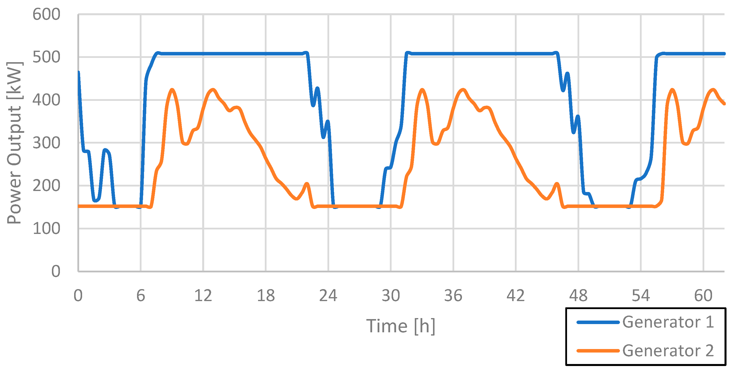
A representation of the current configuration of the UFS rural campus microgrid is illustrated in Figure 1. The actual time series data from the UFS rural campus microgrid [9] were used in determining the DG usage pattern to satisfy demand. A summary of the properties of the microgrid can be found in Table 1, and [9] was consulted for further background information. Using Hybrid Optimization of Multiple Energy Sources (HOMER) [10] as a simulation tool to determine the DG set usage pattern, a worst-case scenario, which is the longest period in the time series where the DG set operates above a minimum load of 30%, was identified (Figure 2). The worst-case scenario took place over a period of 62 h.
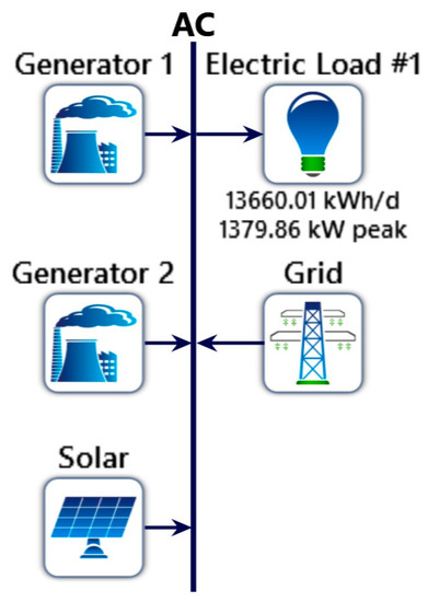
Figure 1.
UFS rural campus microgrid configuration [9].

Table 1.
UFS rural campus microgrid properties and statistics of 2019 [11].
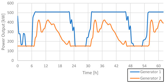
Figure 2.
Generator set power output time series during the worst-case scenario.
The amount of thermal energy generated through waste heat during the worst-case scenario is determined. Diesel has a typical specific energy of 38 MJ per liter [11], equating to a total waste heat of 9.5 MJ to 15.2 MJ per liter of diesel. Using the time series data from [9], it could be determined that a total of approximately 130,313.95 MJ (36.2 MWh) of thermal energy is available through the waste heat to be stored for later use. To determine the waste heat temperature, Equation (1) is used, with a flow rate () of 1.75 kg/s per DG [12] and a specific heat (cp) of 1.009 kJ/kg·K [13]:
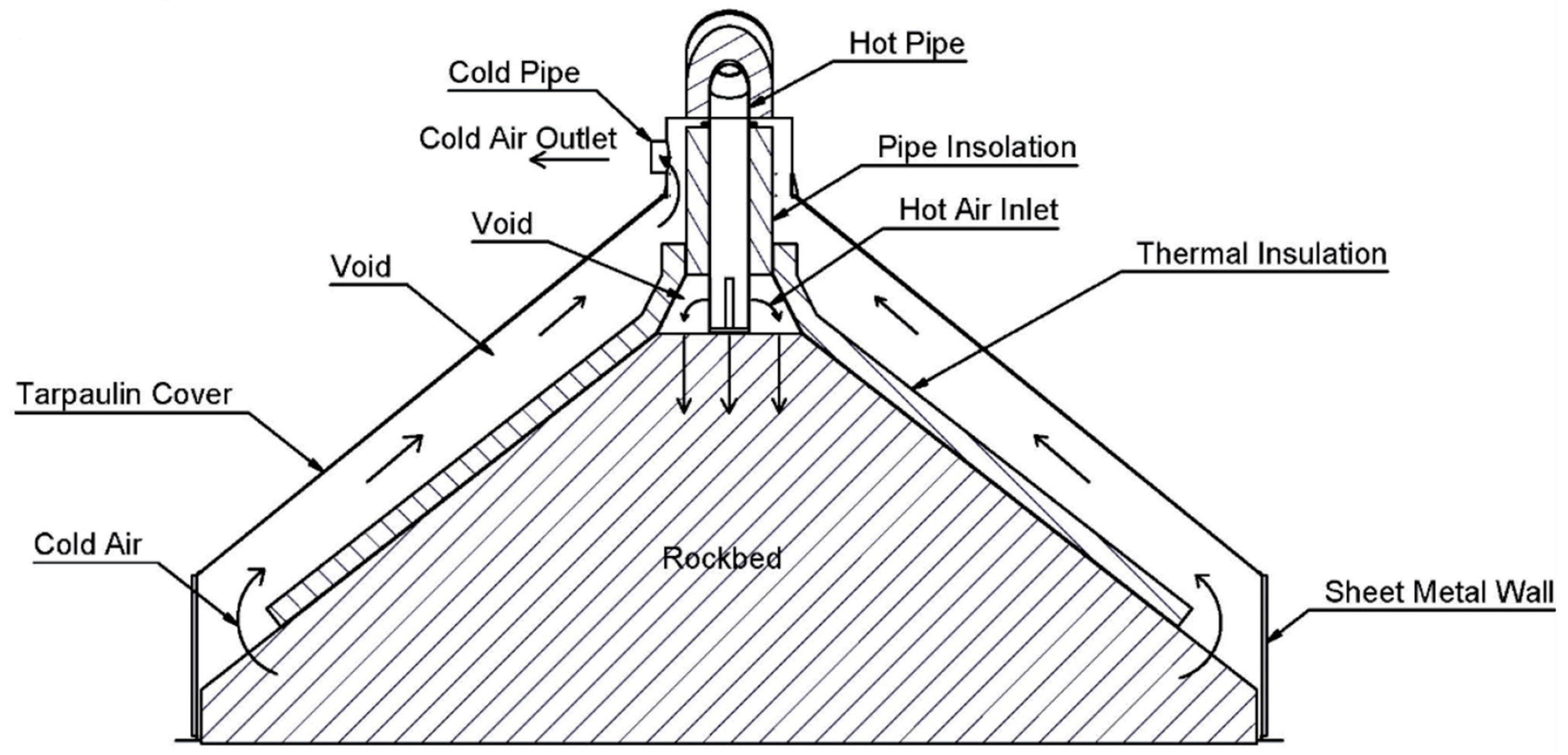
A suitable TES system needed to be identified that would be able to store the determined amount of thermal energy, while being an economically and practically viable solution for a rural microgrid. With air as the already available heat transfer fluid (HTF), TES systems that use air as HTF were considered, eliminating a heat transfer stage and thus an opportunity for heat loss. A rock bed TES system was found to be a suitable solution, using air as HTF and rocks as a storage medium. Rock bed TES systems have a capital cost of 14.09 USD/kWhth [14], compared to a molten salt TES system (22–30 USD/kWhth) [15]. Dolerite is a readily available rock type in South Africa and can be used as a storage medium for thermal energy [16]. Figure 3 illustrates a rock bed TES system developed by [14], which yielded a volumetric efficiency of 61% and an overall efficiency of 94.24% over three charge–store–discharge cycles.
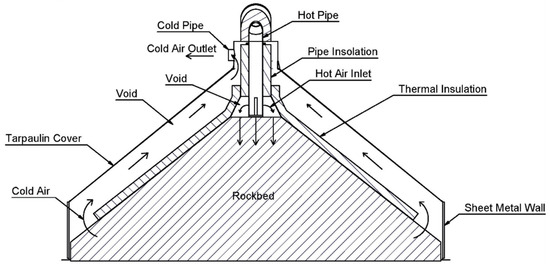
Figure 3.
Rock bed TES (adopted from [14]).
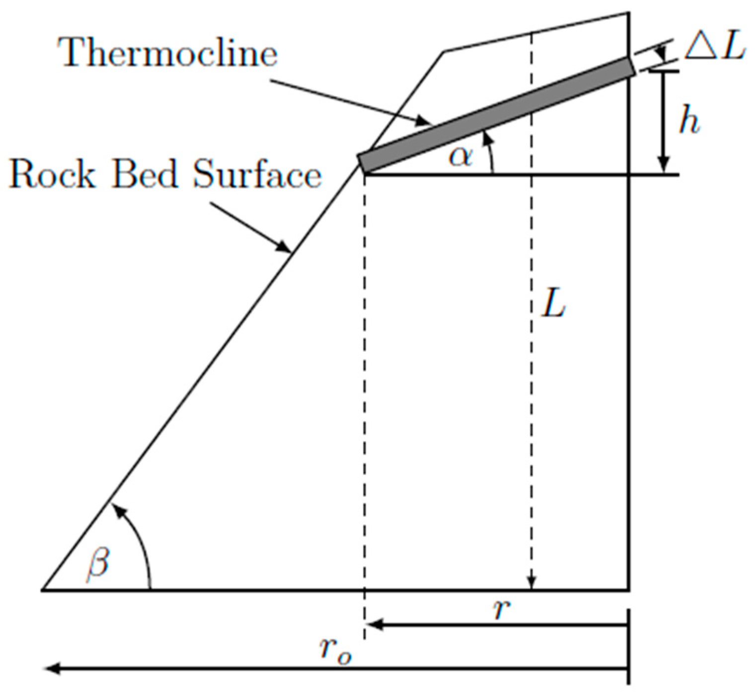
An analytical model was developed to evaluate the potential of storing thermal energy from waste heat. Based on a theory developed and verified [17], the analytical model represents a one-dimensional heat transfer plane. Using Figure 3 as reference, the rock bed has a conical shape, and through experimental campaigns [14], the progression of the heat transfer (thermocline) could be approximated, as illustrated in Figure 4. The thickness of the vertical progression is governed by the typical diameter of a dolerite rock. The shape of the thermocline is caused by the heat following the path of least resistance, which is situated between the rock bed and the thermal insulation material. The progression angle is represented by α, with L the rock bed height, ro the rock bed outer radius, ri the radius of the thermocline, h the thermocline height, ΔL the thermocline thickness and β the natural angle of the rock bed.
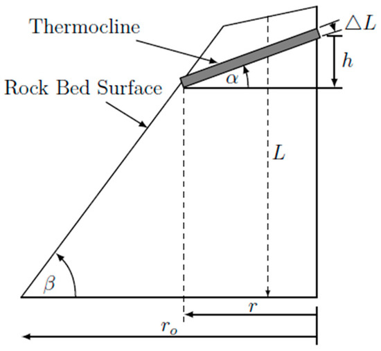
Figure 4.
Thermocline behavior (adopted from [14]).
The following equations are used to determine the volume of each vertical progression step:
Heat progression through the rock bed is modelled stepwise, with each step being the size of that of a typical dolerite rock. Heat transfer between each progression step is analytically determined through use of the effectiveness number of transfer units (e-NTU) method due to the dominant heat transfer type being forced convection [17]. This is confirmed by [18], illustrating that the e-NTU method is suitable for modelling a one-dimensional heat transfer. The e-NTU method makes use of a value known as the number of transfer units, given in Equation (5) [17], which is a correlation between the cross-sectional area of the computational domain and the length of the rock bed. The number of transfer units include the heat transfer coefficient , mass flux , and specific heat of air . represents the equivalent rock diameter for spheres. The void fraction in the rock bed is represented by in Equation (7), and in Equation (8), represents the thermal conductivity of air and the Nusselt number. More on the e-NTU method can be found in [12,15].
with
and
A critical factor in understanding the heat transfer efficiency and thermal energy storage within the TES system is that of the energy balance. The heat transfer relationship between a fluid and solid is explored.
Two energy balances exist within a TES system: the energy balance of the HTF and the energy balance of the storage medium within the TES system. In this case, the HTF is the waste heat from the DG set, and the storage medium is dolerite. Due to fluid mass entering and exiting the TES system, the HTF operates within an open control volume. The opposite is true for the storage medium, as no mass exists in or enters the TES system. The heating capacity of the HTF is determined using Equation (9) from [13]
where is the temperature difference between the HTF and the storage medium, and is the mass flow rate of the HTF. The total energy input into the TES is calculated by Equation (10), which accumulates the energy input to the TES system over time.
The stored energy within the TES system is determined through Equation (11), with Equation (12) [17] calculating the heating capacity of the storage medium.
The heat transfer efficiency can then be calculated through Equation (13).
The amount of thermal energy available for storage was used in an iterative process within the analytical model to determine the size of the TES. The final properties of the TES can be found in Table 2.
Table 2.
TES properties.
The initial parameters of the thermal energy can be found in Table 3. With each DG producing waste heat at a flow rate of 1.75 kg/s, the DG set has a flow rate of 3.5 kg/s. The temperature from the waste heat ranges between 110 and 257 °C, as obtained from Equation (1).
Table 3.
Initial parameters.
A charge duration of 62 h, with a fluctuation temperature inlet, yielded a total of 36.04 MWhth of energy stored in the rock bed TES from the available 36.20 MWhth available from the waste heat, with a storage efficiency of 99.56%. The volumetric efficiency (percentage of rock used for storage) is 100% and the capacity of the rock bed TES is determined to be 581.29 kWth. Volumetric efficiency is defined as the volumetric number of rocks that store energy compared to the total amount of rocks within the TES system. The average inlet temperature was 183 °C over the 62 h period. These results are summarized in Table 4.
Table 4.
Analytical model results.
As mentioned in Section 2 paragraph 2, one liter of diesel equates to 38 MJ, which is 10.56 kWh. Assuming a diesel generator efficiency of 32–53% [19], to achieve the same amount of electrical energy through a diesel generator as the amount of thermal energy stored in the TES, a total of approximately 8056.95 L of diesel needs to be combusted. This equates to a carbon emission reduction of 21.13 tons of CO2. Of course, thermal energy and electrical energy cannot realistically be compared 1:1 and are dependent on the energy conversion strategy chosen for the stored thermal energy. For example, assuming that the conversion efficiency from thermal energy to electrical energy is the same as that of a diesel generator, the carbon emission reduction will range from 6.67 to 11.20 tons of CO2.
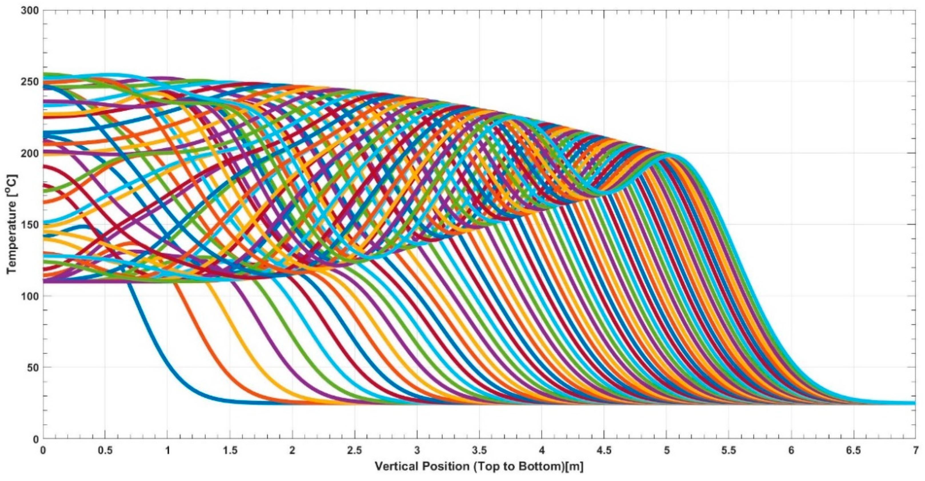
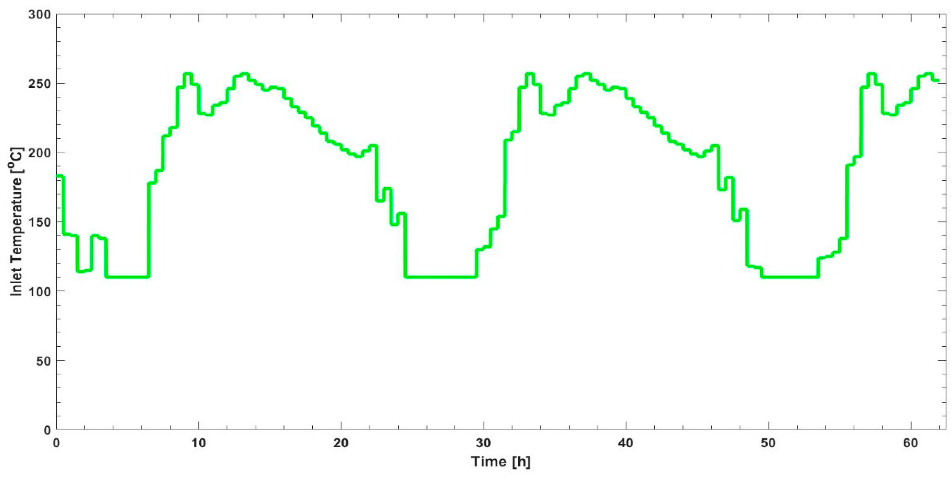
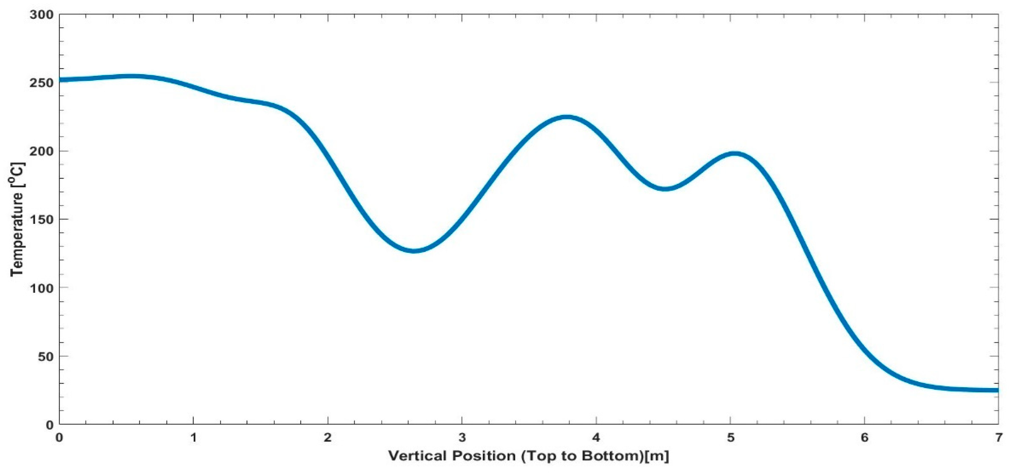
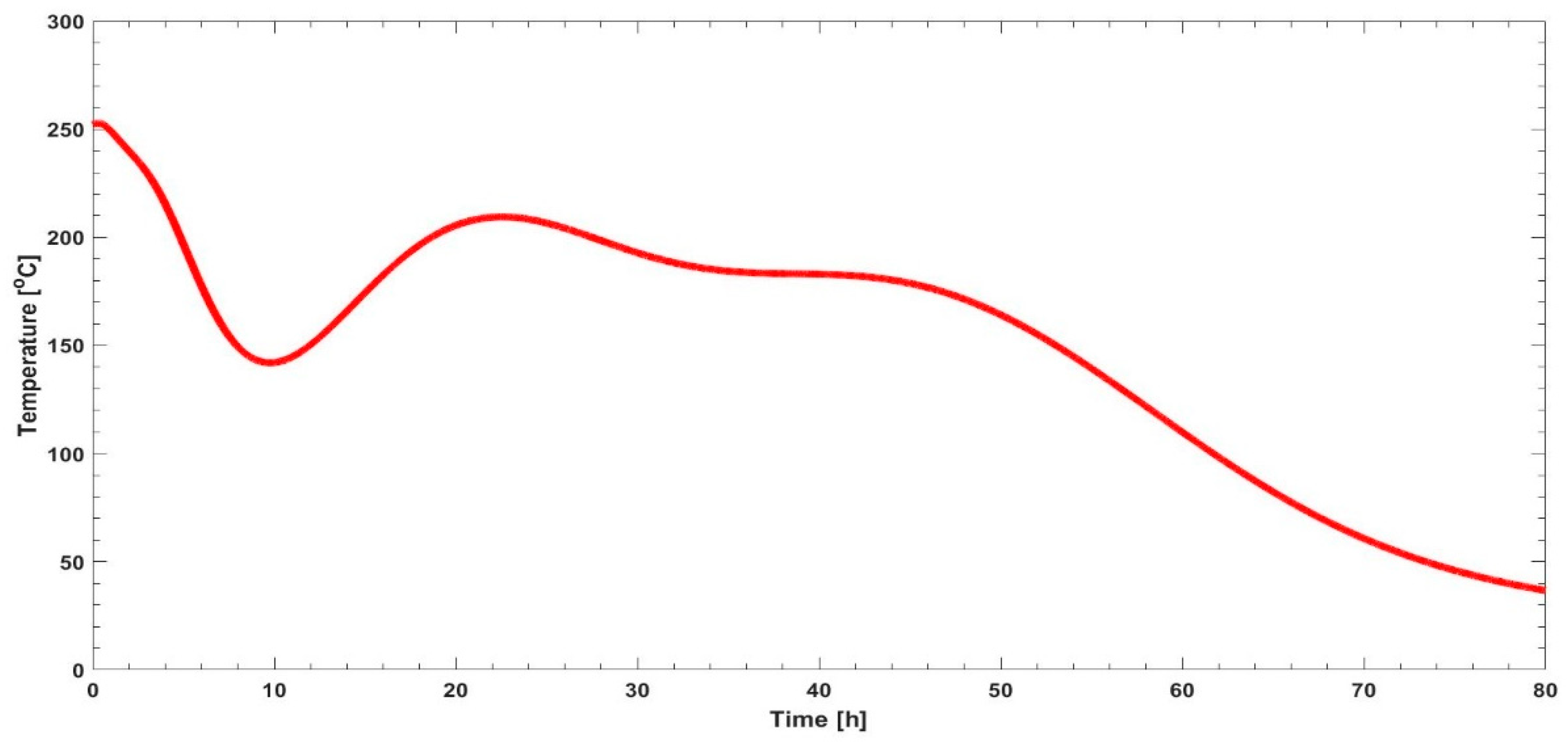
Figure 5 illustrates the hourly temperature distribution within the rock bed from hour 1 to hour 62 (each hour represented by a line) when taking a slice in the middle of the rock bed from top to bottom. Since the rock bed has a conical shape, it can be assumed that the temperature distribution is the same throughout the rock bed at each thermocline. An interesting observation can be made from Figure 5, which shows an oscillation starting at a high amplitude, decreasing through the rock bed, and tending towards a steady-state equilibrium. The inlet temperature to the rock bed, thus the temperature received from the waste heat of the DG set, can be observed in Figure 6. Figure 7 depicts the final temperature distribution after a 62 h charge cycle. An 80 h discharge cycle resulted in the outlet temperature profile illustrated in Figure 8.
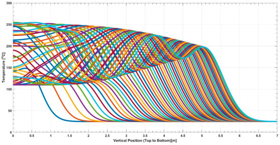
Figure 5.
Temperature distribution in the rock bed from top (0 m) to bottom (7 m).
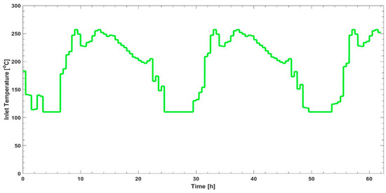
Figure 6.
Inlet temperature to the TES system.
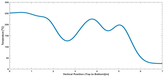
Figure 7.
Final temperature distribution in the rock bed, after 62 h of charging, from top (0 m) to bottom (7 m).
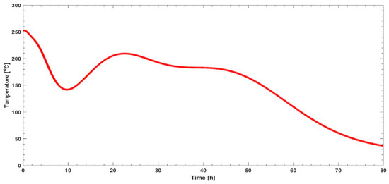
Figure 8.
Outlet temperature during an 80 h discharge cycle.
3. Discussion
Waste utilization was investigated through an analytical model, quantifying the energy availability and the induced dynamics of generator variability within a TES system. Rural campus microgrids offer a unique setting, amplifying the variability within a TES system. Time series data, depicting a worst-case use (see Figure 2), determined the capacity of the TES (see Table 2) to maximize energy storage from the waste heat. Due to the low cost of rock bed TES systems, the maximization strategy only involves charging to eliminate instances of energy loss.
The TES system was charged for a 62 h period (see Figure 2), storing 36.04 MWhth of energy, with an efficiency of 99.56%. Included in the time series data is the variability of the available energy through the DG set waste heat. Variability in both PV and demand is considered a critical driver for observed variability in waste heat production. Temperature distribution in the TES (see Figure 5) is initially governed by the variability in waste heat production. This variability is illustrated by the inlet temperature to the rock bed (Figure 6) from the waste heat produced by the DG set, with the DG set waste heat production being governed by the load demand on the DG set. From Figure 8, it is evident that the outlet temperature profile is dependent on the temperature distribution of the fully charged rock (see Figure 7 and Appendix A for a timelapse of the rock bed temperature distribution from hour 1 to hour 62). This means that should the discharge cycle start at any given time, the discharge profile would be governed by the temperature distribution in the rock bed TES at that time. The outlet temperature is thus not only dependent on the discharge flow rate, but also the time instance at which the discharge is initiated.
Through the above experimental results, two utilization paradigms were identified, namely, deferable (time-independent) and non-deferable (time-dependent). Non-deferable utilization will be governed by the intermittency of PV coupled with grid unavailability. Through this strategy, waste heat is utilized instantaneously, which implicates that the available temperature will vary, as per Figure 8, depending on the chosen time interval. The chosen time interval governs the type of application the waste heat can be utilized for. Deferable utilization will be independent of the intermittency of PV and grid unavailability and will typically be governed by the scenarios where the stored waste heat is truly excess energy and not utilized in non-deferable cases. Through this strategy, after some time, the rock bed TES will reach a steady temperature distribution state, allowing for a uniform temperature outlet that can be utilized for a specific application. The latter observations remain the key contributions of this paper within the paradigm of rural microgrids.
For application purposes within the non-deferable paradigm, certain applications require a certain temperature profile. The outlet temperature profile will determine which applications are feasible in which instances. However, the outlet temperature profile can be altered by the flow rate to accommodate specific applicational needs. The focus is to extract the amount of energy needed for an application, realizing that the energy is dependent on the extraction flow rate and temperature distribution in the rock bed, of which is strongly influenced by the initial variability of the PV and demand profiles.
Storing thermal energy from waste heat enables the reduction of carbon emissions. The thermal energy will be able to substitute the electrical energy from the generators for various applications, causing a reduction in diesel that needs to be consumed by die DGs. The reduction in diesel consumption reduces carbon emissions. The investigation of the worst-case scenario confirms the latter, where generating the amount of electrical energy to match the available thermal energy from the waste heat would take 8056.95 L of diesel. In this case, it is not possible to quantify the exact amount of carbon emission reduction which takes place, as it depends on the type of application the thermal energy from the waste heat is used for. It is however worthy to note the carbon emission reduction strategy that is applicable to the rural campus microgrid system that includes a TES system. It is noted that the analytical model does not quantify certain variables, such as radiational and conductive heat transfer. Further investigation in Computational Fluid Dynamics (CFD) and experimental verification is necessary to minimize the uncertainty associated with the temperature distribution profile.
4. Conclusions
This paper investigated the utilization of waste heat produced by DGs in a rural campus microgrid. The following contributions were made to the field:
- Waste heat can be stored in a rock bed TES, regardless of the variability in available waste heat.
- Variability of the PV and demand does have an effect on the temperature distribution profile of the rock bed TES. This leads to the realization of two utilization paradigms, deferable and non-deferable.
- Non-deferable utilization is time-dependent, hence utilizing the immediately available thermal energy and influencing the application of the stored energy.
- Deferable utilization is time-independent after an extended time, utilizing thermal energy when the TES reaches a stable, uniform temperature state.
- Carbon emission reduction takes place through the reduction in diesel usage due to an alternative source of energy, waste heat, being utilized for applications previously served by diesel generation.
The identified utilization paradigms can form part of the demand-side management strategy of a rural campus microgrid. The unpredictable availability of the grid, coupled with the intermittency of the PV, forces the Qwaqwa rural campus microgrid to operate within the non-deferable paradigm. These findings could be applied in scenarios such as automated extraction strategies for various applications that depend on the predicted temperature distribution profile beforehand. Further theoretical considerations could include using stochastic models to describe the available waste heat.
Stochastic modelling can be used to estimate the probability of obtaining certain waste heat outcomes while incorporating various degrees of random movement in the input parameter space. Both utilization paradigms, uncovered in this paper, depend on inlet temperatures that are governed by three critical variability generators: PV generation, campus demand and grid availability. In order to serve applications in the non-deferrable (instantaneous) paradigm, a mathematical description of the inlet temperature will be needed for accurate dispatch strategies based on the instantaneous available waste heat. For this reason, future endeavours will include the process of determining the probability density function for the available waste heat to serve as an inlet temperature for the rock bed TESS, based on stochastic models for each of the variability generators. The available waste heat will be described by a stochastic model governed by the uncertainties in the microclimate, randomness in the load profile and the unpredictability of grid availability. The global waste heat stochastic model will further clarify which cluster of non-deferrable utilizations can be optimally served. Unlocking the global waste heat stochastic model will enable the accurate determination of the energy saved (via waste heat utilization), while the rural campus microgrid operates in islanded mode. Furthermore, a global waste heat stochastic model description will ultimately allow for certainty and adaptability when considering energy export opportunities or utility frequency support. Lastly, future work will explore the interplay between diesel-based generation and the load removed from the network via the utilization of stored waste heat, more specifically, diesel generation subjected to load reduction realized by diesel generation waste heat utilization. The latter interplay (or dynamical perturbation) will add an additional component to the global waste heat stochastic model that will ultimately influence the ability to predict the amount of available stored waste heat for deferrable loads within a required time interval. The creation of an open-source module (Matlab and Python compatible) combines waste heat utilization with rock bed energy storage for use in environmental economic optimization and microgrid control models. The aforementioned module can also be combined with power system dynamics to investigate possible frequency support strategies.
Author Contributions
Conceptualization, S.E. and J.M.; methodology, S.E.; software, S.E.; validation, S.E.; formal analysis, S.E.; investigation, S.E.; resources, S.E. and J.M.; data curation, J.M.; writing—original draft preparation, S.E. and J.M.; writing—review and editing, S.E. and J.M.; visualization, S.E and J.M. All authors have read and agreed to the published version of the manuscript.
Funding
This research received no external funding.
Data Availability Statement
The data is not publicly available; however, the author can be contacted should the data be of interest to the reader.
Conflicts of Interest
The authors declare no conflict of interest.
Nomenclature
| Indexes | |
| a | Air |
| amb | Ambient |
| cs | Cross-section |
| f | Final |
| ht | Heat Transfer |
| i | inner |
| in | Into the rock bed |
| o | outer |
| r | Rock |
| st | Stored |
| th | Thermal |
| WH | Waste Heat |
| Greek Symbols | |
| α | Progression angle [°] |
| β | Natural angle of the rock bed [°] |
| Δ | Difference [-] |
| Void fraction [-] | |
| Efficiency [%] | |
| Parameters | |
| A | Area [m2] |
| Specific heat of air [kJ/kg.K] | |
| Dv | Equivalent rock diameter [m] |
| E | Energy [Joule] |
| G | Mass flux [kg/m2.s] |
| h | Thermocline height [m] |
| hv | Heat transfer coefficient [W/m2.K] |
| k | Thermal conductivity [W/m.K] |
| L | Rock bed height [m] |
| Mass flowrate [kg/s] | |
| Nu | Nusselt number [-] |
| Heat Transfer Rate [kJ/s] | |
| T | Temperature [K] |
| t | Time [s] |
| r | Radius [m] |
| Units | |
| °C | Degrees Celsius |
| J | Joule |
| K | Kelvin |
| kJ | Kilojoule |
| kg | Kilogram |
| kVA | Kilo |
| kWh | Kilowatt-hour |
| kWp | Kilowatt-peak |
| GWh | Gigawatt-hour |
| L | Liter |
| m | Meter |
| m3 | Cubic-meter |
| MJ | Megajoule |
| mm | millimeter |
| MWh | Megawatt-hour |
| s | seconds |
| W | Watt |
| List of Abbreviations | |
| CFD | Computational Fluid Dynamics |
| CO2 | Carbon dioxide |
| DG | Diesel Generator |
| e-NTU | Effectiveness Number of Transfer Units |
| GDP | Gross Domestic Product |
| GHG | Greenhouse Gas |
| HES | Hydrogen Energy Storage |
| HOMER | Hybrid Optimization of Multiple Energy Sources |
| HTF | Heat Transfer Fluid |
| PCM | Phase Change Materials |
| PV | Photovoltaic |
| TES | Thermal Energy Storage |
| UFS | University of the Free State |
| USD | United States Dollar |
Appendix A
A video illustrating the propagation of the thermocline inside the rock bed over a charge cycle of 62 h is observed. Note how the variability of the inlet temperature influences the temperature distribution.
References
- Warrick, P.; Ferreira, B. Statistics of Utility-Scale Power Generation in South Africa in 2021. Council for Scientific and Industrial Research. 2022, pp. 1–211. Available online: https://www.csir.co.za/sites/default/files/Documents/20220503-StatisticsofpowerinSAH2-2021-CSIR-%5BFINAL%5D%281%29.pdf (accessed on 17 May 2022).
- South African Reserve Bank. Electricity Load Shedding and Economic Activity; South African Reserve Bank: Pretoria, South Africa, 2019; Available online: https://www.resbank.co.za/content/dam/sarb/publications/quarterly-bulletins/boxes/2019/9517/Electricity-load-shedding-and-economic-activity.pdf (accessed on 13 June 2023).
- Kumar, A.; Singh, A.R.; Deng, Y.; He, X.; Kumar, P.; Bansal, R.C. A Novel Methodological Framework for the Design of Sustainable Rural Microgrid for Developing Nations. IEEE Access 2018, 6, 24925–24951. [Google Scholar] [CrossRef]
- Nasir, M.; Khan, H.A.; Hussain, A.; Mateen, L.; Zaffar, N.A. Solar PV-based scalable DC microgrid for rural electrification in developing regions. IEEE Trans. Sustain. Energy 2018, 9, 390–399. [Google Scholar] [CrossRef]
- Cole, W.; Will Frazier, A. 2019. Cost Projections for Utility-Scale Battery Storage. Golden, CO: National Renewable Energy Laboratory. NREL/TP-6A20-73222. Available online: https://www.nrel.gov/docs/fy19osti/73222.pdf (accessed on 24 May 2022).
- Wang, Y.; Fang, S.; Xu, Y. On control of energy storage systems in microgrids. In Power System; Springer: Berlin/Heidelberg, Germany, 2021; pp. 289–304. [Google Scholar] [CrossRef]
- Hossain, S.N.; Bari, S. Waste heat recovery from exhaust of a diesel generator set using organic fluids. Procedia Eng. 2014, 90, 439–444. [Google Scholar] [CrossRef]
- Kawamoto, R.; Mochizuki, H.; Moriguchi, Y.; Nakano, T.; Motohashi, M.; Sakai, Y.; Inaba, A. Estimation of CO2 Emissions of internal combustion engine vehicle and battery electric vehicle using LCA. Sustainability 2019, 11, 2690. [Google Scholar] [CrossRef]
- Erasmus, S.; Esterhuysen, N.; Maritz, J. Campus Microgrids within the South African Context: A Case Study to Illustrate Unique Design, Control Challenges, and Hybrid Dispatch Strategies. Energies 2023, 16, 1519. [Google Scholar] [CrossRef]
- Lambert, T.; Gilman, P.; Lilienthal, P. Micropower System Modeling with Homer. In Integration of Alternative Sources of Energy; Farret, F.A., Simões, M.G., Eds.; John Wiley and Sons: Hoboken, NJ, USA, 2005. [Google Scholar] [CrossRef]
- NSW Department of Primary Industries. Comparing Running Costs of Diesel, LPG and Electrical Pumpsets; NSW Department of Primary Industries: Orange, Australia, 2016. Available online: www.dpi.nsw.gov.au (accessed on 25 May 2022).
- Ghoreishi-Madiseh, S.A.; Safari, A.; Amiri, L.; Baidya, D.; De Brito, M.A.R.; Kuyuk, A.F. Investigation of viability of seasonal waste heat storage in rock piles for remote communities in cold climates. Energy Procedia 2019, 159, 66–71. [Google Scholar] [CrossRef]
- Çengel, Y.A.; Boles, M.A. Thermodynamics: An Engineering Approach, 8th ed.; McGraw-Hill: New York, NY, USA, 2015. [Google Scholar]
- Erasmus, S.J.; Von Backström, T.W.; Lubkoll, M.; Dinter, F. Design and Development of a Next Generation Thermal Rock Bed Storage Experimental Facility. 2019. Available online: http://hdl.handle.net/10019.1/105862 (accessed on 25 May 2022).
- Allen, K.; Von Backström, T.; Joubert, E.; Gauché, P. Rock bed thermal storage: Concepts and costs. AIP Conf. Proc. 2016, 1734, 050003. [Google Scholar] [CrossRef]
- Laubscher, H.F.; Von Backström, T.W.; Dinter, F. Developing a cost effective rock bed thermal energy storage system: Design and modelling. AIP Conf. Proc. 2017, 1850, 080015. [Google Scholar] [CrossRef]
- Allen, K.G.; von Backström, T.W.; Kröger, D.G. Rock bed pressure drop and heat transfer: Simple design correlations. Sol. Energy 2015, 115, 525–536. [Google Scholar] [CrossRef]
- Duffie, J.; Beckman, W. Solar Engineering of Thermal Processes, 4th ed.; Wiley: Hoboken, NJ, USA, 2013. [Google Scholar]
- Jakhrani, A.Q.; Rigit, A.R.H.; Othman, A.K.; Samo, S.R.; Kamboh, S.A. Estimation of carbon footprints from diesel generator emissions. In Proceedings of the 2012 International Conference on Green and Ubiquitous Technology, Bandung, Indonesia, 7–8 July 2012; pp. 78–81. [Google Scholar] [CrossRef]

Disclaimer/Publisher’s Note: The statements, opinions and data contained in all publications are solely those of the individual author(s) and contributor(s) and not of MDPI and/or the editor(s). MDPI and/or the editor(s) disclaim responsibility for any injury to people or property resulting from any ideas, methods, instructions or products referred to in the content. |
© 2023 by the authors. Licensee MDPI, Basel, Switzerland. This article is an open access article distributed under the terms and conditions of the Creative Commons Attribution (CC BY) license (https://creativecommons.org/licenses/by/4.0/).