Article

Bypass Configurations of Membrane Humidifiers for Water Management in PEM Fuel Cells

1
Department of Mechanical Engineering, Graduate School, Chungnam National University, 99 Daehak-ro, Yuseong-gu, Daejeon 34134, Republic of Korea
2
School of Mechanical Engineering, Chungnam National University, 99 Daehak-ro, Yuseong-gu, Daejeon 34134, Republic of Korea
*
Author to whom correspondence should be addressed.
Energies 2023, 16(19), 6986; https://doi.org/10.3390/en16196986
Submission received: 31 August 2023 / Revised: 29 September 2023 / Accepted: 3 October 2023 / Published: 7 October 2023
(This article belongs to the Special Issue Hydrogen and Fuel Cell Technology, Modelling and Simulation II)

Abstract

:
Water management is an important criterion in the operation of proton-exchange membrane fuel cells to maintain the high performance and reliability of the system. The water content in the cathode air that is supplied to the cathode channel contributes to the membrane humidification and the transport of protons inside the membrane structure. In automotive applications, the supply air is typically driven through an external membrane humidifier to absorb more moisture from the recirculated cathode exhaust. In the literature, humidifiers and fuel cell stacks have been separately investigated without considering whole-system configurations for water management. This study investigates changes in the cathode air characteristics through a membrane humidifier and compares two configurations using a humidifier bypass of the supply flow and exhaust flow to adjust the cathode inlet air relative humidity. Each component in the system was modeled using mathematical relations and converted into blocks of inputs and outputs in MATLAB/Simulink for simulation. The bypass valve was demonstrated to effectively reduce the relative humidity of the supply air from the saturation rate to above 60%, with a bypass fraction of up to 0.6 in both configurations. These adjustments provide system flexibility to accommodate load changes and prevent flooding in the stack channels. Bypassing the supply air through the humidifier effectively maintained consistent cathode inlet humidity across a wide operational range. A 0.4 bypass fraction on the supply side sustained a relative humidity of around 80% for the whole range of operating flow rates. In contrast, the exhaust-side bypass had a smaller impact, and the relative humidity of the cathode air was reduced when the flow rate and bypass fraction increased. This study further supports the control system design to regulate the bypass fraction according to load transients.

1. Introduction

Proton-exchange membrane fuel cells (PEMFCs) generate electricity from reactions between hydrogen and oxygen that take place inside a stack of bipolar plates and membranes. The membranes separate the cathode and anode channels and allow protons to move through during operations [1]. One of the critical challenges of PEMFCs is water management. Since the high proton conductivity and durability of the membrane relies on a high water content, the membrane should be humidified either by internal or external humidification processes [2]. However, flooding inside the stack channels could also result in low performance and air blockage [3]. The impact of the cathode inlet relative humidity current density, as well as the operating current density, is considerably clearer in the case of large-scale applications of PEMFCs. Flooding effects in the cathode’s gas distribution layer may potentially have a detrimental influence on the cell performance because of the higher power and current density requirements of these applications [4]. Another issue is load fluctuations, which pose a significant challenge in maintaining stable air supply conditions to the PEMFC stack. For decarbonization goals, the integration of PEMFCs with renewable energy sources offers a promising system to mitigate the intermittency inherent in these sources. While hybrid systems provide a continuous and reliable energy supply, the air supply to the fuel cell stack should be regulated in response to changes in demand to ensure stack performance and durability—particularly when power production from renewable sources fluctuates [5,6]. Therefore, maintaining the desired water content of the supply air is critical and requires an understanding of the humidifier and system configurations.
The humidification process can be carried out before the reactants enter the stack or inside the stack. Although internal humidification processes are also utilized, they have the disadvantages of being more complex and expensive. External humidifiers are more effective for air and hydrogen supply flows, which are suitable for large-scale and low-cost PEMFCs [7]. This type of humidifier can be categorized by a variety of methods, such as gas bubbling, enthalpy wheel humidification, or membrane humidification using exhaust gas recirculation. The membrane humidifier has the advantages of high water-vapor permeability, simple design, low cost, and a compact size, which is suitable for automotive applications [7]. This study focuses on hollow membrane humidifiers placed outside the stack to humidify the supply air.
The modeling and simulation of humidification processes for PEMFC have been researched extensively in recent years. The membrane humidifier has been analytically modeled by the heat and mass transfer phenomena from the water in the shell and the gas in the membrane tubes [8]. In some studies, this humidifier was considered to be ideal and static [9]. These studies assumed a desired value of the supply-air relative humidity at the humidifier outlet, and other characteristics were calculated based on this humidity. These assumptions were made to focus on stack modeling and simulations, which simplified the role of the humidifier. In other studies, water transport through the membrane humidifier was analytically investigated through one-dimensional models and experiments [10,11]. The modeling of water transport can be started from pressure or concentration differences between the membrane boundaries. Water transport is estimated by determining the integral along the membrane length from the inlet to the outlet [10]. Alternatively, bulk flows in the channels can generate concentration differences that drive the flux [11]; the effects of operating parameters and design parameters on this have been illustrated through modeling and simulation.
The regulation of relative humidity in the inlet gas is essential for optimizing cell performance. An excessively high value of relative humidity or extremely low values can result in a reduction of cell efficiency, with the effects manifesting as either ohmic loss due to membrane dehydration or mass transport loss due to channel blockages. Ozen et al. [12] conducted an experiment that demonstrated that increasing the cathode relative humidity from 26 to 100% improved the PEMFC performance significantly, and their findings also showed that changes in the cathode relative humidity had a more significant impact on cell performance than changes in the anode relative humidity. Jeong et al. [13] investigated the effect of the cathode relative humidity and the operating current density on cell performance. Their studies showed that when operating at lower current densities (60 mA/cm2), the output voltage of the cell increased when the relative cathode humidity was raised from 20% to 100%. In contrast, when operating at higher densities (above 340 mA/cm2), a high water-generation rate that was greater than the water evaporation rate—combined with an increase in the cathode relative humidity—may cause difficulties in water removal, resulting in flooding in the cathode channel. As a result, there was a declining trend in the cell output voltage. The phenomenon mentioned above of flooding, concerning the current density and relative humidity, was further demonstrated by Jamekhorshid et al. [14]. Their model concluded that a higher power demand (increased anode stoichiometry) and higher cathode relative humidity (above 60%) could make the system more at risk for floods. The importance of finding an optimal range for the relative humidity was shown in Janicka et al.’s examination [15]. Their measurement concluded that the relative humidity of the inlet gases should be above 50% at a lower current density, and for operation at a higher current density, a lower relative humidity value below 30% was set to obtain the best performance.
This research investigates a humidification module, including a membrane humidifier and two configurations of a bypass valve and mixer, to manage the relative humidity of the cathode inlet air. The modeling and simulation results provide valuable insights into supply air’s water management for system design and control.

2. Model Descriptions

2.1. Membrane Humidifier

In automotive applications, an external humidifier is used to supplement the water content of the incoming air to the cathode. Rather than sourcing water from an external source, the recirculated flow from the cathode exhaust is reused as the source. Transport of the vapor is carried out through membranes, which are specifically fabricated to only allow water to pass through its structure. This process ensures that other pollutants or particles are not included in the humidified air. A schematic diagram of the membrane humidifier applied in this study is illustrated in Figure 1. A bundle of membrane tubes is placed inside the shell to form two channels for flows. The dry flow moves inside the tubes and absorbs water particles from the outside flow. The counterflow configuration can be seen as similar to the heat exchanger. However, both heat and mass transfer phenomena happen in this device.
The membrane humidifier was modeled as a moisture exchanger with a bundle of membranes inside a housing. The model in this study aimed to describe the dynamics of the supply air’s characteristics at the inlets and exits of the humidifier. The changes in the relative humidity of the humidified flow were expressed through mathematical relations with inlet parameters. It should be noted that the model makes several assumptions, including:
  • The flows are perfectly distributed in the shell and tubes;
  • Effects of tube-to-tube heat and mass transfer are neglected to focus on the shell-and-tube exchange;
  • The transportation is considered perpendicular to the flow directions, while the transportation in parallel with the flow is negligible;
  • Counterflow arrangement is fully developed inside the shell and tubes, and therefore, the heat and mass transfer follow counterflow correlations at all parts along the flows.
The humidifier model in this study was developed using the effectiveness-NTU method to determine the heat and mass transfer rates in the membrane bundle.
The general equation for the effectiveness ( ε i ) of the humidifier is described as [16]:
ε i = 1 exp N T U i C i 1 1 C i × exp N T U i C i 1
where the terms ε i , N T U i , C i denote the heat transfer effectiveness ( ε h ), the number of transfer units for heat ( N T U h ), and the heat capacity ratio ( C h ), and the mass transfer effectiveness ( ε m ) the number of transfer units for mass ( N T U m ), and the mass flow rate ratio ( C m ), respectively. The number of transfer units is determined by [17]:
N T U h = U h A ( m ˙ c ) m i n
N T U m = ρ U m A m ˙ m i n
In addition, the term C i has different forms for each analysis:
C h = ( m ˙ c ) m i n ( m ˙ c ) m a x
C m = m ˙ m i n m ˙ m a x
Calculation of the number of transfer units can be carried out using the overall heat transfer coefficient and overall mass transfer coefficient. The coefficients were computed based on the heat conduction and convection for heat transfer, and the mass diffusion and convection for vapor transport at the two surfaces and inside the membranes [18].
The heat transfer rate ( q t ) and mass transfer rate ( m ˙ t ) are:
q t = ε h m ˙ c m i n ( T e T s )
m ˙ t = ε m m ˙ m i n ( ω e ω s )
Table 1 provides the main parameters of the humidifier model. The membranes in this study were selected according to our previous experimental work on mass transport through a hollow fiber membrane humidifier [19]. The membrane was developed based on polytetrafluoroethylene (PTFE) structures. It is thinner than Nafion 115 and 117, but thicker than Nafion 211 and 212.
The relative humidity and approach dewpoint temperature were used as indicators for the humidifier performance, together with the mass transfer rate. The approach dewpoint temperature ( A d ) is the difference between the dewpoint temperatures of the cathode exhaust flow supplied to the humidifier wet side inlet ( T d e , i ) and the humidified outlet air ( T d s , o ):
A d = T d e , i T d s , o
The dewpoint temperature can be approximately calculated by using the formula from Lawrence [20]:
T d = B 1 ( l n φ + A 1 T B 1 + T ) A 1 l n φ A 1 T B 1 + T         ( A 1 = 17.625 ,   B 1 = 243.04 ,   T   i n   C )
The relative humidity of the flow can be estimated by the specific humidity ( ω ), temperature ( T ), and pressure ( P ) [21]:
φ = ω P ( 0.622 + ω ) P s a t T
where the saturation pressure can be determined through Antoine’s equation:
P s a t T = 10 3 × 10 A B C + T ( A = 7.16728 , B = 1716.984 , C = 232.538 , T   i n   C )

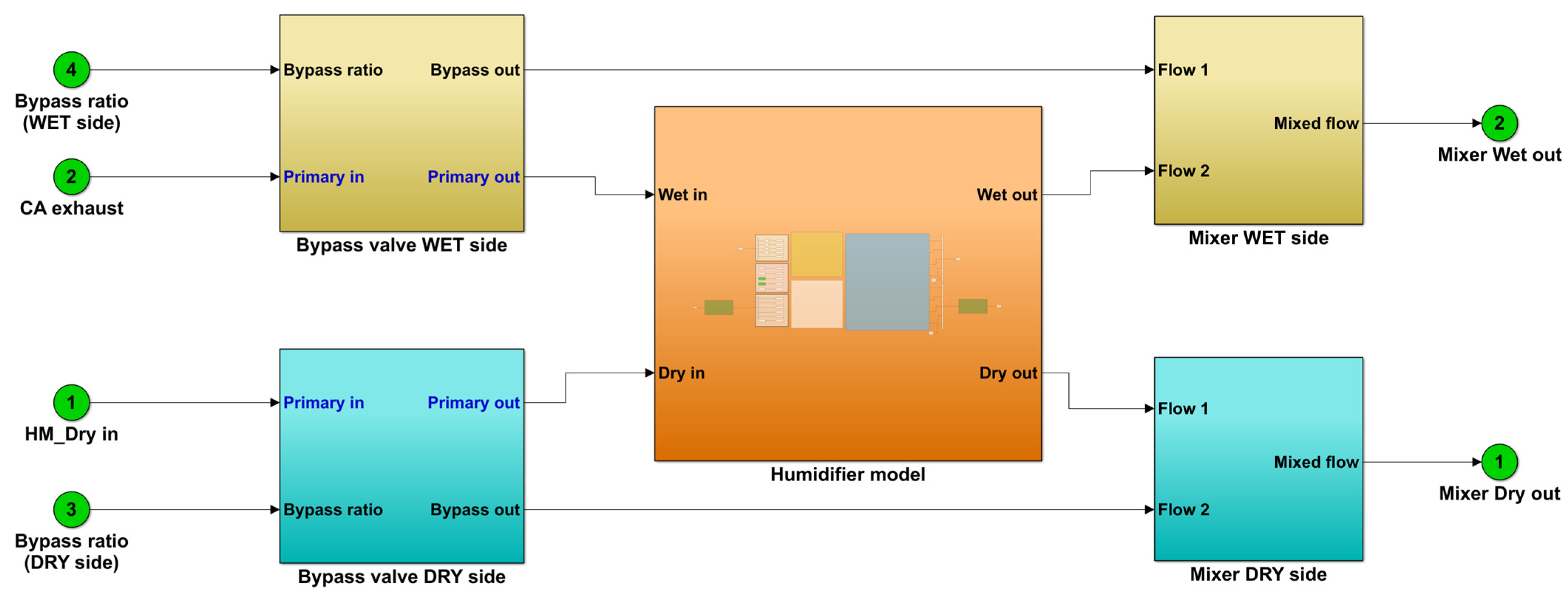
2.2. Bypass Valve and Mixer

The bypass valve separates the supply air to the primary flow and the bypass flow depending on the valve opening area. Two arrangements of the humidifier and the bypass valve in the fuel cell system were considered in this study, which are illustrated in Figure 1. The first arrangement directs a ratio of supply air bypassing the humidifier to adjust the relative humidity of the cathode inlet flow. In the second arrangement, the cathode exhaust is managed to bypass the humidifier to reduce the water source for humidification, which reduces the relative humidity of the flow to the cathode. In both cases, the primary flow was then mixed with the bypass flow in a mixer placed after the humidifier.
The bypass fraction ( f ) is determined by the ratio between the bypass mass flow rate and the total mass flow rate:
f = m ˙ b p m ˙ t o
After going through the bypass valve and humidifier, the flows were mixed in an ideal mixer. The mixer model follows fundamental correlations in thermodynamics:
m ˙ m i x = m ˙ 1 + m ˙ 2
T m i x = X 1 T 1 + X 2 T 2
P m i x = X 1 P 1 + X 2 P 2
ω m i x = m ˙ 1 , v + m ˙ 2 , v m ˙ 1 , a + m ˙ 2 , a
The relative humidity of the mixed flow is calculated through the absolute humidity, as in the above section. The humidifier, bypass valve, and mixer are combined as a module to regulate the relative humidity in the cathode flow. The humidifier module is connected to the fuel cell stack and other components of the PEMFC system, which are described in the next section.

2.3. Fuel Cell Stack

A central fuel cell stack model consists of four integral elements: the anode and cathode for the fuel transport and electrochemical processes, a membrane for ion transport, and electrochemistry for the fuel cell voltage calculation.

2.3.1. Anode Channel

The anode channel uses humidified hydrogen as intake gas. The molar flow balance equations for an anode channel are as follows:
d M ˙ H 2 d t = M ˙ H 2 , i M ˙ H 2 , o M ˙ H 2 r e a c t
d M ˙ H 2 O a n d t = M ˙ H 2 O , i a n M ˙ H 2 O , o a n M ˙ m
where M ˙ H 2 , i ,   M ˙ H 2 O , i a n ,   M ˙ H 2 , o ,   M ˙ H 2 O , o a n ,   M ˙ H 2 r e a c t ,   a n d   M ˙ m are the hydrogen and water inlet molar flow, outlet flow, reaction rate, and membrane water transport, respectively.
The molar fraction of hydrogen and water in the inlet flow is calculated by:
X H 2 O , i a = φ i a n P S A T T s t P a
X H 2 , i = 1 X H 2 O , i a n
According to Faraday’s law, the molar flow rate of hydrogen and water at the anode inlet are described as follows:
M ˙ H 2 , i = v H 2 i 2 F
M ˙ H 2 O , i a n = v H 2 i 2 F X H 2 O , i a n X H 2 , i
where v H 2 is the hydrogen stoichiometry ratio.
The molar flow rate at the outlet of the anode channel:
M ˙ H 2 , o = ( v H 2 1 ) i 2 F
M ˙ H 2 O , o a n = M ˙ H 2 O , i a n M ˙ m
The anode channel’s relative humidity:
φ a n = P H 2 O a n P S A T T s t
The partial pressure of hydrogen and water inside the anode channel can be calculated using the molar fraction of gas in the channel and the channel pressure:
P H 2 a n = X H 2 P a n  
P H 2 O a n = X H 2 O P a n

2.3.2. Cathode Channel

The cathode channel gas inlet comprises oxygen, water, and nitrogen. The molar flow balance equations of the cathode channel can be expressed as:
d M ˙ O 2 d t = M ˙ O 2 , i M ˙ O 2 , o M ˙ O 2 r e a c t
d M ˙ H 2 O c a d t = M ˙ H 2 O , i c a M ˙ H 2 O , o c a M ˙ H 2 O p r o d u c t + M ˙ m
d M ˙ N 2 d t = M ˙ N 2 , i M ˙ N 2 , o
The molar fraction of water in the inlet flow is calculated by:
X H 2 O , i c a = φ a c a P S A T T s t P c a
The reaction rate of oxygen and the production rate of water in the cathode channel are calculated using Faraday’s law:
M ˙ O 2 r e a c t = i 4 F
M ˙ H 2 O p r o d u c t = i 2 F    
The molar flow rate at the outlet of the anode channel:
M ˙ O 2 , o = ( v O 2 1 ) i 4 F
where v O 2 is the oxygen stoichiometry ratio.
M ˙ H 2 O , o c a = M ˙ H 2 O , i c a + M ˙ H 2 O p r o d u c t + M ˙ m
Nitrogen is considered an inert gas, and therefore:
M ˙ N 2 , i = M ˙ N 2 , o
The cathode channel’s relative humidity and partial pressure of oxygen and water are calculated according to Equations (25)–(27).

2.3.3. Membrane Water Transport

Electro-osmotic drag, back diffusion, and convection are the three transport mechanisms that control the transport of water through the membrane.
Assuming that convectional water transport is ignored because the pressure in the anode and cathode channels is uniform, the movement of water through the membrane can be represented as follows:
N m = n d × i F D i γ w c a γ w a n t m
where n d ,   D i ,   γ w c a ,   a n d   γ w a are the electro-osmotic coefficient, diffusion coefficient, and water concentration at the cathode and anode, respectively. They can be calculated using the equations below [22,23]:
n d = 0.0029 λ 2 + 0.05 λ 3.4 × 10 19
D i = D i λ e x p 2416 1 303 1 T s t
D i λ = 2.563 0.33 λ + 0.0264 λ 2 0.00067 λ 3 , λ > 4 3 1.38 λ 3 , 3 < λ 4 1 + 2 ( λ 2 ) , 2 < λ 3 1 , λ 2
γ w = ρ a M a λ    
The membrane water content ( λ ) can be calculated through the water activity [22]:
λ = 14 + 14 ( a 1 ) ,     1 < a 3 0.043 + 17.81 a 39.85 a 2 + 36 a 3 ,     0 < a 1

2.3.4. Electrochemistry

The actual voltage of the fuel cell can be calculated by subtracting the open-circuit potential with cell losses (ohmic loss and electrode overpotential). The overpotential of the anode is insignificant compared to the cathode channel, and thus, neglected in this calculation.
V c e l l = O C V η o h m η c a
Using Nernst’s law, the open-circuit voltage is a function of the stack temperature and the partial pressure of hydrogen and oxygen [23]
O C V = 1.229 0.85 × 10 3 T s t 298.15 + 4.3085 × 10 5 T s t l n ( P H 2 P O 2 0.5 )
Multiplication of the current density and ohmic resistance yields the ohmic loss. The ohmic resistance of fuel is made up of the resistance of the electrodes, the resistance of the interconnects, and the resistance of the membrane. Since the membrane’s resistance accounts for most of the resistance [24], the other resistances are neglected in this calculation.
η o h m = i t m σ m
The membrane’s conductivity σ m is expressed by a function depending on the stack temperature and the membrane’s water content [25]:
σ m = 0.005319 λ 0.00326 exp 1268 1 303 1 T s t
In this study, an aggregation model was employed to simulate electrochemical reactions within the catalyst layer of a PEMFC. The reaction is influenced by the temperature, pressure, and structure. The cathode overpotential is calculated using Ohm’s law [26]:
η c a = i K e f f z c l
The parameters used in the 100 kW stack model are described in Table 2. More detailed information on the stack model and other components in the system model, such as the compressor, intercooler, and hydrogen supply, can be found in our previous study [26,27].

2.4. Simulation

The mathematical equations described above were loaded into the MATLAB/Simulink platform to simulate different configurations of the humidifier, bypass valve, and mixer. Figure 2 describes the simulation blocks of the humidification module developed in Simulink. The humidification module was first separately considered to study the effects of the mass flow rate, bypass configuration, bypass fraction, and humidifier size on the cathode inlet characteristics, with assumptions made for the supply air and cathode exhaust. The humidification module was then integrated into the fuel cell system model to investigate the humidifier’s responses to the changes in current demand. In this case, the compressor and intercooler components provided the air’s characteristics at the humidifier’s dry side inlet, while the stack component delivered the cathode exhaust information to the humidifier’s wet side. Table 3 summarizes the simulation cases and the purposes of this study.

3. Discussions

3.1. Effects of Mass Flow Rate and Bypass Fraction

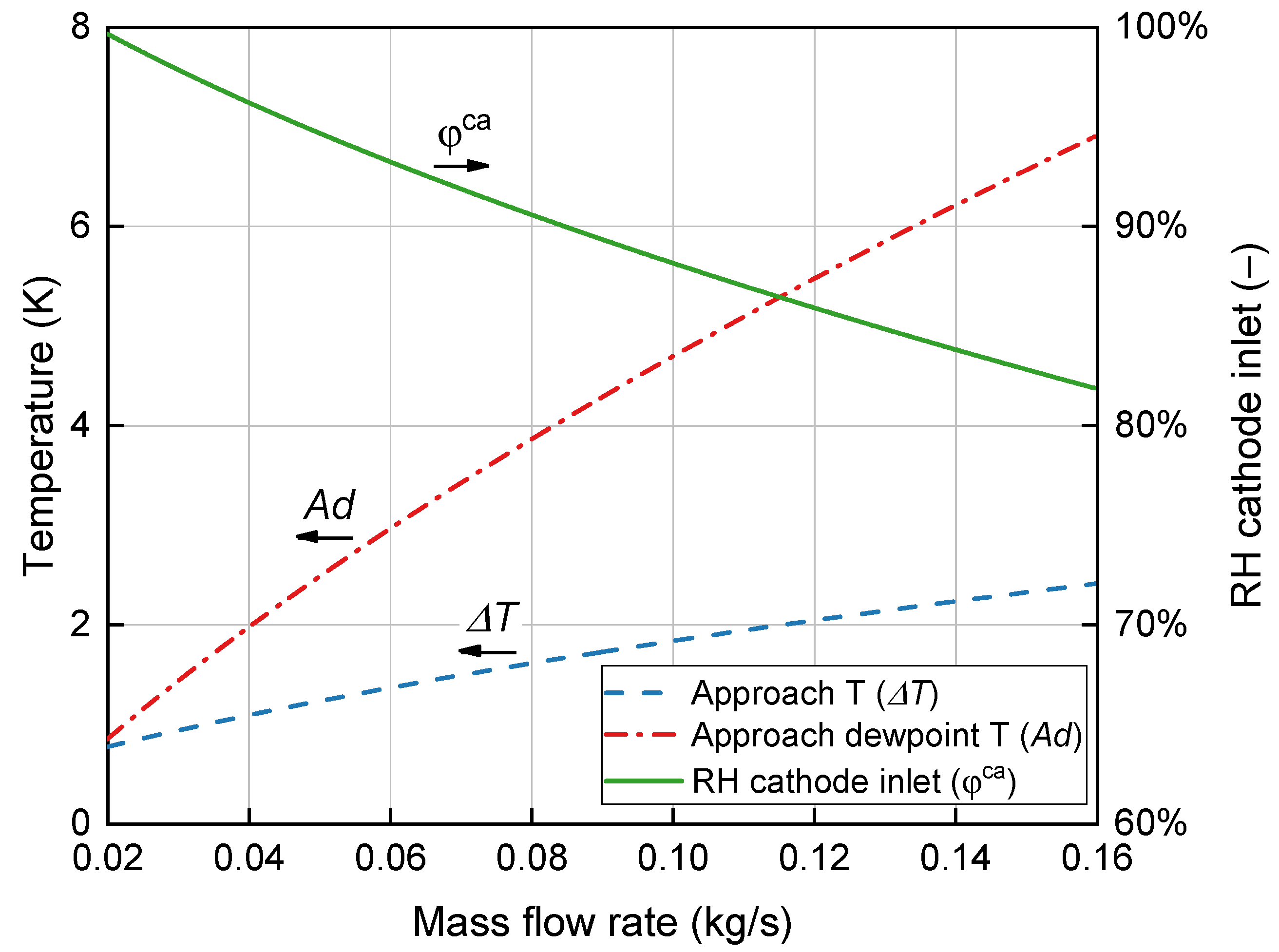
3.1.1. Humidifier Performance with Increasing Load Demand

In this operational scenario, the mass flow rate within both the supply air and the cathode exhaust witnessed an increase in the typical system configuration without bypass. This elevation in the flow rates highlights the imposition of augmented load demands on the fuel cell system. As depicted in Figure 3, the simulation results illustrate relative humidity and approach temperature changes due to varying mass flow rates on the supply side. Spanning the range of flow rates from 0.02 kg/s to 0.16 kg/s, the relative humidity of the cathode air progressively diminished from an initial state of near saturation to a level surpassing 80%. Concurrently, the approach temperature steadily increased from 1 K to 7 K, amplifying discrepancies between the temperature of the supply air and that of the cathode exhaust. The reduction in temperature enhanced the water content of the humidified flow, standing in contrast to the effects of the increased dry supply air.
A parallel trajectory was observed in the approach dewpoint temperature, encapsulating a trend of diminishing moisture content in the air. As the mass flow rate escalated, the humidifier generated relatively lower humidity levels in the humidified flow. Adjustments in the relative humidity of the flow may necessitate implementation to prevent flooding in the stack channels. This underscores the intricacies of maintaining optimal conditions within the fuel cell system, further reinforcing the significance of the humidification process in achieving desirable performance outcomes.

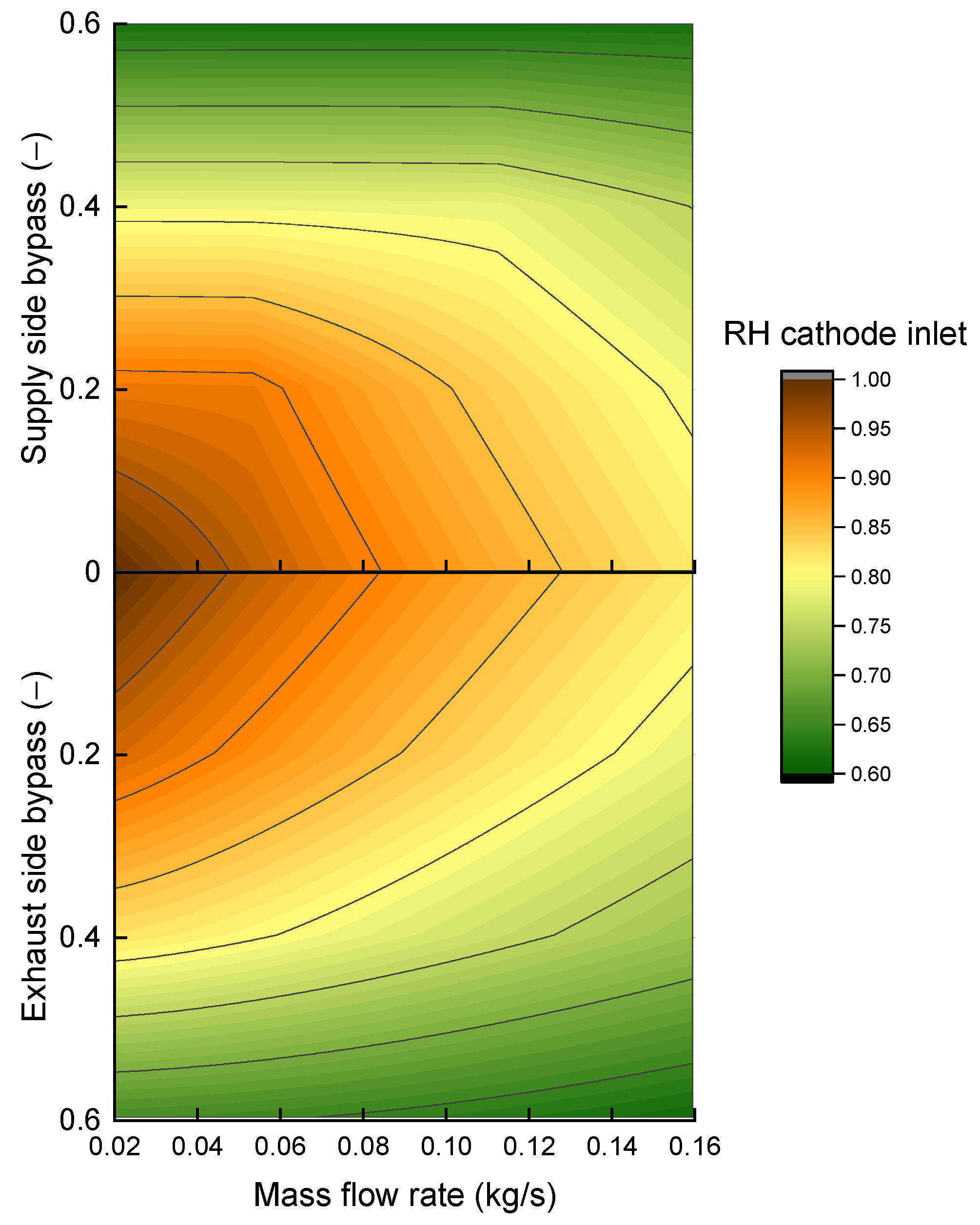
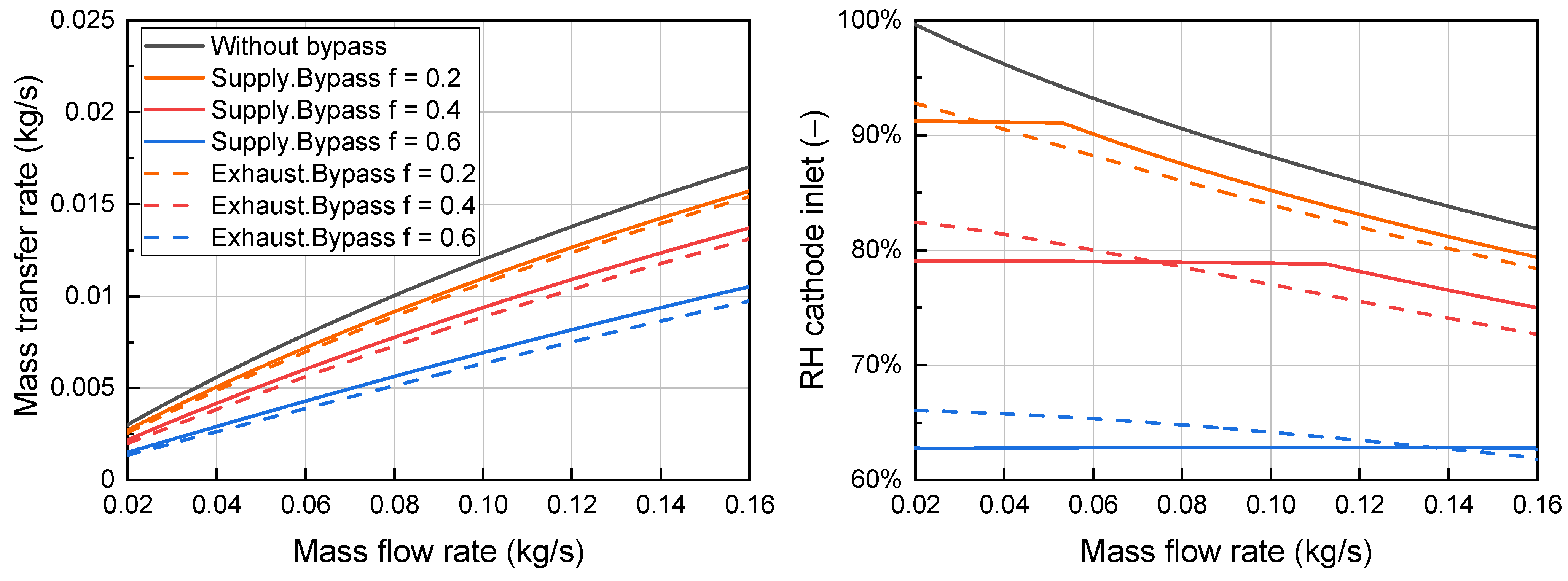
3.1.2. Flow Rate Adjustments with Humidifier Bypass

A bypass was added to the system to adjust the relative humidity in the supply air in two configurations: on the supply side and the exhaust side. Figure 4 compares the humidifier’s performance at different bypass fractions on each side of the humidifier. The cathode air relative humidity approached saturation levels with a low flow rate and bypass fraction. Increasing the bypass fraction on either side reduced the cathode air relative humidity to around 60%. The exhaust side bypass was more sensitive to flow rate changes than the supply side bypass under the same bypass fraction.
Figure 5 provides a closer look at the mass transfer rate and the relative humidity of the humidification module. In the conventional arrangement without bypass, all the supply air was directed through the humidifier towards the cathode manifold, resulting in the highest mass transfer rate. As the load increased, the mass transfer rate correspondingly escalated, culminating in a peak value of 0.017 kg/s. This augmentation boosted the vapor concentrations on both sides of the membranes, enhancing the potential for water particle exchange. However, a simultaneous decline in the relative humidity within the cathode air had been observed, indicative of the diminished water content within the supply flow.
When the bypass valve was introduced, a reduction in vapor transport became evident for both supply and exhaust side configurations. With an increase in bypass fraction from 0.2 to 0.6, the mass transfer rate could be reduced by approximately 10–40%. The bypass valve effectively governed vapor transport from the exhaust gas to the supply flow. A distinction emerged in the impact on the humidity of these two configurations. In instances where the exhaust side was bypassed, the relative humidity of the cathode inlet flow exhibited a gradual decline. Conversely, when the supply side was bypassed, the relative humidity was maintained at a level even as the mass flow rate increased.
For a supply-side bypass fraction of 0.2, the relative humidity remained at 91% within the lower mass flow rate range, up to 0.05 kg/s. Similarly, for a bypass ratio of 0.4, the relative humidity of the supply air remained steady at around 80% until the mass flow rate reached 0.11 kg/s. A lower relative humidity of 63% was observed when 60% of the supply air was diverted through the bypass channel. This humidity level remained consistent across the mass flow rate range. This is because of the mixing of saturated vapor from the humidifier outlet with dry air from the bypass channel. Particularly during periods of low demand, when a portion of the flow moved through the bypass channel, the humidifier generated high humidity at the outlet, which subsequently mixed with the dry bypass flow. Therefore, bypassing and mixing the supply flow maintained a stable relative humidity.
Employing the supply flow bypass led to smoothing the relative humidity characteristic curves, effectively sustaining the humidity levels over a wide operational range and mitigating the effects of rising mass flow rates. For the bypass valve on the exhaust side, the mixed flow after the humidifier is directed to the tailpipe, with the reduction in relative humidity within the cathode air contingent solely upon increasing demand. In some fuel cell systems, after passing through the humidifier, the remaining energy from the exhaust flow is recovered by an expander attached to the compressor.

3.2. Effects of Humidifier Size

The effects of increasing the humidifier’s size on the humidifier’s performance were simulated with different numbers of membranes, ranging from 7000 to 16,000, as described in Figure 6. The supply bypass fraction was changed from 0 to 0.6 in each graph to demonstrate the effects on the cathode inlet relative humidity. The humidity rate increased when a higher number of membranes were installed and at a low flow rate in the system. Sizing the humidifier at 7000 membrane tubes resulted in the lowest outlet relative humidity of 75% at 0.12 kg/s supply air. The highest amount of humidity was 97% at a low flow rate of 0.04 kg/s and with the highest number of membranes, 16,000. Bypassing the supply side of the humidifier significantly reduced the relative humidity by mixing humidified flow with bypass flow in the mixer. When the humidifier size increased, the bypass effects on relative humidity reduction experienced higher levels. Particularly, there was an effect of water saturation at the humidifier outlet mixing with the dry bypass flow, which lowered the relative humidity and flattened the characteristic curve. In the simulation case of 0.04 kg/s, with a supply bypass fraction of 0.2, the humidity rate increased with a humidifier size up to 10,000. For bigger sizes, the rate remained above 90%. For higher bypass fractions, the effects on the relative humidity were dominated by the bypass, while the humidifier size had minimal effects. The effects of bypassing and mixing the supply flow could also be observed at higher flow rates of 0.08 and 0.12 kg/s under a bypass fraction of 0.4. At the highest bypass fraction of 0.6, the relative humidity remained stable, even though the number of membranes increased significantly in the simulation range.
The bypass configuration in the exhaust channel also reduced the humidity rate within the humidified air in a different way. In comparison to the humidifier size ranges at which saturation and mixing happened in the supply bypass cases, greater reductions in the outlet relative humidity could be seen in the exhaust bypass setup. After the effects of the supply-side bypass had dominated the influence on the cathode humidity, the exhaust-side bypass had lower relative humidity reductions.

3.3. Integration into the Fuel Cell System

The humidifier model was integrated with other components to form the fuel cell system model. Simulations were performed with different load demands to observe the responses of the humidifier. As presented in Figure 7, the current demand increased and then decreased with step changes in the range of 0.3–0.7 A/cm2. These changes required the compressor to follow and provide a corresponding mass flow rate, which was then supplied to the humidifier. The characteristics of the humidifier dry-side inlet depend on the compressor and intercooler models. In addition, the dynamics of the cathode exhaust determined the flow characteristics on the wet side. The changes in the relative humidity of the humidified flow reflect the influences of other components on the humidifier dynamics.
The relative humidity responded in opposite directions to demand changes. The current density increase led to an increased mass flow rate to the humidifier and a decreased cathode inlet humidity. This is because dry airflow to the humidifier inlet increased much faster than increasing the water transfer rate from the wet-side inlet. In this simulation case, the cathode air relative humidity varied from 55–80%, with higher rates at lower current densities. The humidifier performed better in low demand, from 0.3–0.6 A/cm2, and produced a humidity rate of under 60% at higher loads, from 20–40 s. There were also delays in the relative humidity changes compared to the current demand and stack power due to slow transients in the flow characteristics.

4. Conclusions

This study developed an analytical model for a humidification module, which includes a humidifier, bypass valve, and mixer. These elements collaborated to regulate the water content in the supply air directed to the fuel cell stack. Through a simulation and the comparison of two humidifier bypass configurations, valuable insights were gained. The bypass valve was demonstrated to effectively reduce the relative humidity of the supply air from the saturation rate to above 60%, with a bypass fraction of up to 0.6 in both configurations. These adjustments provided system flexibility to accommodate load changes and prevent flooding in the stack channels. Bypassing the supply air through the humidifier emerged as an effective strategy for finely tuning the water content in the cathode inlet flow. This method maintained a consistent cathode inlet flow relative humidity regardless of load fluctuations across a wide operational range. Specifically, when a bypass fraction of 0.4 was employed on the supply side, the relative humidity remained at approximately 80% throughout the entire operational range of mass flow rates for the 100-kW fuel cell system.
On the other hand, bypassing on the exhaust side had a slightly smaller impact on the cathode relative humidity. In this case, the relative humidity decreased as the operating flow rate and bypass fraction increased. For a fixed bypass fraction, this configuration was unable to maintain stable relative humidity when the flow rate changed, as seen in the supply-side bypass. However, this approach offers an alternative pathway for electricity recovery through expander-based regeneration. In addition to the bypass fractions and bypass configurations, this study also provides the simulation findings of humidifier size effects on the humidifier’s performance. The humidifier model was then integrated into the fuel cell system model, facilitating system performance simulations across varying load demands. This study could aid in designing and optimizing efficient water management in fuel cell systems adaptable to diverse conditions.

Author Contributions

Conceptualization, H.N.V. and S.Y.; formal analysis, H.N.V. and D.H.T.; funding acquisition, S.Y.; investigation, H.N.V. and D.T.L.T.; methodology, H.N.V. and S.Y.; project administration, S.Y.; resources, D.H.T.; software, H.N.V. and D.T.L.T.; supervision, S.Y.; validation, D.H.T. and D.T.L.T.; visualization, H.N.V. and D.T.L.T.; writing—original draft, H.N.V.; writing—review and editing, H.N.V. and S.Y. All authors have read and agreed to the published version of the manuscript.

Funding

This research was funded by the National Research Foundation of Korea (No. 2020M1A2A2080860) and the Korea Institute of Energy Technology Evaluation and Planning (No. 20203010030010).

Data Availability Statement

The data presented in this study are available upon request from the corresponding author.

Acknowledgments

This work was supported by the National Research Foundation of Korea (No. 2020M1A2A2080860), a grant funded by the Ministry of Science, ICT and Future Planning; and the Korea Institute of Energy Technology Evaluation and Planning (KETEP) and the Ministry of Trade, Industry and Energy (MOTIE) of the Republic of Korea (No. 20203010030010).

Conflicts of Interest

The authors declare no conflict of interest.

Nomenclature

A area
A d approach dewpoint temperature
c heat capacity
C heat capacity ratio
d membrane thickness
D diameter
D i diffusion coefficient
F Faraday’s constant
f bypass fraction
g gravitational acceleration
h convective heat transfer
i current density
K electric conductivity
m ˙ mass flow rate
M ˙ molar flow rate
n number of membranes
n d electro-osmotic coefficient
N T U number of transfer units for heat transfer analysis
O C V open-circuit voltage
P pressure
q heat transfer rate
t thickness
T temperature
T d dewpoint temperature
U overall heat transfer coefficient
V voltage
X molar fraction
z distance
Greek letters
γ water concentration
ε effectiveness
η overpotential
λ membrane water content
ρ density
σ membrane conductivity
φ relative humidity
ω specific humidity
Subscripts and superscripts
a dry air
a n anode
b p bypass
c e l l fuel cell
c a cathode
c l catalyst layer
e exhaust gas from cathode
e f f effective
f manifold
h heat transfer
i inlet
m membrane/mass transfer
m i n minimum
m a x maximum
o outlet
p r o d u c t production
r e a c t reaction
s supply air
s a t saturation
t transfer
t o total flow rate
v vapor
w water

References

  1. Jiao, K.; Xuan, J.; Du, Q.; Bao, Z.; Xie, B.; Wang, B.; Zhao, Y.; Fan, L.; Wang, H.; Hou, Z.; et al. Designing the next Generation of Proton-Exchange Membrane Fuel Cells. Nature 2021, 595, 361–369. [Google Scholar] [CrossRef] [PubMed]
  2. Hassan, N.S.M.; Daud, W.R.W.; Sopian, K.; Sahari, J. Water Management in a Single Cell Proton Exchange Membrane Fuel Cells with a Serpentine Flow Field. J. Power Sources 2009, 193, 249–257. [Google Scholar] [CrossRef]
  3. Chen, B.; Wang, J.; Yang, T.; Cai, Y.; Zhang, C.; Chan, S.H.; Yu, Y.; Tu, Z. Carbon Corrosion and Performance Degradation Mechanism in a Proton Exchange Membrane Fuel Cell with Dead-Ended Anode and Cathode. Energy 2016, 106, 54–62. [Google Scholar] [CrossRef]
  4. Yan, S.; Yang, M.; Sun, C.; Xu, S. Liquid Water Characteristics in the Compressed Gradient Porosity Gas Diffusion Layer of Proton Exchange Membrane Fuel Cells Using the Lattice Boltzmann Method. Energies 2023, 16, 6010. [Google Scholar] [CrossRef]
  5. Al-Bonsrulah, H.A.Z.; Alshukri, M.J.; Mikhaeel, L.M.; Al-Sawaf, N.N.; Nesrine, K.; Reddy, M.V.; Zaghib, K. Design and Simulation Studies of Hybrid Power Systems Based on Photovoltaic, Wind, Electrolyzer, and Pem Fuel Cells. Energies 2021, 14, 2643. [Google Scholar] [CrossRef]
  6. Eriksson, E.L.V.; Gray, E.M.A. Optimization and Integration of Hybrid Renewable Energy Hydrogen Fuel Cell Energy Systems—A Critical Review. Appl. Energy 2017, 202, 348–364. [Google Scholar] [CrossRef]
  7. Chang, Y.; Qin, Y.; Yin, Y.; Zhang, J.; Li, X. Humidification Strategy for Polymer Electrolyte Membrane Fuel Cells—A Review. Appl. Energy 2018, 230, 643–662. [Google Scholar] [CrossRef]
  8. Park, S.; Jung, D. Effect of Operating Parameters on Dynamic Response of Water-to-Gas Membrane Humidifier for Proton Exchange Membrane Fuel Cell Vehicle. Int. J. Hydrogen Energy 2013, 38, 7114–7125. [Google Scholar] [CrossRef]
  9. Pukrushpan, J.T.; Stefanopoulou, A.G.; Peng, H. Fuel Cell System Model: Auxiliary Components BT. In Control of Fuel Cell Power Systems: Principles, Modeling, Analysis and Feedback Design; Pukrushpan, J.T., Stefanopoulou, A.G., Peng, H., Eds.; Springer: London, UK, 2004; pp. 15–29. ISBN 978-1-4471-3792-4. [Google Scholar]
  10. Park, S.; Oh, I.-H. An Analytical Model of NafionTM Membrane Humidifier for Proton Exchange Membrane Fuel Cells. J. Power Sources 2009, 188, 498–501. [Google Scholar] [CrossRef]
  11. Park, S.-K.; Choe, S.-Y.; Choi, S. Dynamic Modeling and Analysis of a Shell-and-Tube Type Gas-to-Gas Membrane Humidifier for PEM Fuel Cell Applications. Int. J. Hydrogen Energy 2008, 33, 2273–2282. [Google Scholar] [CrossRef]
  12. Ozen, D.N.; Timurkutluk, B.; Altinisik, K. Effects of Operation Temperature and Reactant Gas Humidity Levels on Performance of PEM Fuel Cells. Renew. Sustain. Energy Rev. 2016, 59, 1298–1306. [Google Scholar] [CrossRef]
  13. Jeong, S.U.; Cho, E.A.; Kim, H.J.; Lim, T.H.; Oh, I.H.; Kim, S.H. Effects of Cathode Open Area and Relative Humidity on the Performance of Air-Breathing Polymer Electrolyte Membrane Fuel Cells. J. Power Sources 2006, 158, 348–353. [Google Scholar] [CrossRef]
  14. Jamekhorshid, A.; Karimi, G.; Noshadi, I. Current Distribution and Cathode Flooding Prediction in a PEM Fuel Cell. J. Taiwan Inst. Chem. Eng. 2011, 42, 622–631. [Google Scholar] [CrossRef]
  15. Janicka, E.; Mielniczek, M.; Gawel, L.; Darowicki, K. Optimization of the Relative Humidity of Reactant Gases in Hydrogen Fuel Cells Using Dynamic Impedance Measurements. Energies 2021, 14, 3038. [Google Scholar] [CrossRef]
  16. Bergman, T.L.; Lavine, A.S.; Incropera, F.P.; DeWitt, D.P. Fundamentals of Heat and Mass Transfer, 8th ed.; Wiley: New York, NY, USA, 2018; ISBN 978-1-119-35388-1. [Google Scholar]
  17. Zhang, L.Z. An Analytical Solution for Heat Mass Transfer in a Hollow Fiber Membrane Based Air-to-Air Heat Mass Exchanger. J. Membr. Sci. 2010, 360, 217–225. [Google Scholar] [CrossRef]
  18. Vu, H.N.; Nguyen, X.L.; Yu, S. A Lumped-Mass Model of Membrane Humidifier for PEMFC. Energies 2022, 15, 2113. [Google Scholar] [CrossRef]
  19. Nguyen, X.L.; Vu, H.N.; Yu, S. Parametric Understanding of Vapor Transport of Hollow Fiber Membranes for Design of a Membrane Humidifier. Renew. Energy 2021, 177, 1293–1307. [Google Scholar] [CrossRef]
  20. Lawrence, M.G. The Relationship between Relative Humidity and the Dewpoint Temperature in Moist Air: A Simple Conversion and Applications. Bull. Am. Meteorol. Soc. 2005, 86, 225–233. [Google Scholar] [CrossRef]
  21. Cengel, Y.A.; Boles, M.A. Thermodynamics: An Engineering Approach; McGraw-Hill Education: New York, NY, USA, 2015; ISBN 9780073398174 0073398179. [Google Scholar]
  22. Dutta, S.; Shimpalee, S.; Van Zee, J.W. Numerical Prediction of Mass-Exchange between Cathode and Anode Channels in a PEM Fuel Cell. Int. J. Heat Mass Transf. 2001, 44, 2029–2042. [Google Scholar] [CrossRef]
  23. Pukrushpan, J.T.; Stefanopoulou, A.G.; Peng, H. Fuel Cell System Model: Fuel Cell Stack. In Control of Fuel Cell Power Systems: Principles, Modeling, Analysis and Feedback Design; Pukrushpan, J.T., Stefanopoulou, A.G., Peng, H., Eds.; Springer: London, UK, 2004; pp. 31–56. ISBN 978-1-4471-3792-4. [Google Scholar]
  24. O’Hayre, R.; Cha, S.-W.; Colella, W.; Prinz, F.B. Chapter 4: Fuel Cell Charge Transport. In Fuel Cell Fundamentals; John Wiley & Sons, Inc.: Hoboken, NJ, USA, 2016; pp. 117–166. [Google Scholar]
  25. Springer, T.E.; Zawodzinski, T.A.; Gottesfeld, S. Polymer Electrolyte Fuel Cell Model. J. Electrochem. Soc. 1991, 138, 2334–2342. [Google Scholar] [CrossRef]
  26. Vu, H.N.; Truong Le Tri, D.; Nguyen, H.L.; Kim, Y.; Yu, S. Multifunctional Bypass Valve for Water Management and Surge Protection in a Proton-Exchange Membrane Fuel Cell Supply-Air System. Energy 2023, 278, 127696. [Google Scholar] [CrossRef]
  27. Truong Le Tri, D.; Vu, H.N.; Nguyen, H.L.; Kim, Y.; Yu, S. A Comparative Study of Single and Dual Ejector Concepts for Anodic Recirculation System in High-Performance Vehicular Proton Exchange Membrane Fuel Cells. Int. J. Hydrogen Energy 2023, 48, 27344–27360. [Google Scholar] [CrossRef]
Figure 1. Different configurations of water management in humidifier module.
Energies 16 06986 g001
Figure 2. Simulink blocks of the humidification module.
Energies 16 06986 g002
Figure 3. Effects of supply air mass flow rate on relative humidity and approach temperature.
Energies 16 06986 g003
Figure 4. Bypass fractions and effects on cathode inlet relative humidity.
Energies 16 06986 g004
Figure 5. Humidifier performance under different bypass configurations.
Energies 16 06986 g005
Figure 6. Effects of humidifier size on the performance.
Energies 16 06986 g006
Figure 7. Responses of the humidifier in load transients and system performance.
Energies 16 06986 g007
Table 1. Parameters of the humidifier model.
ParameterUnitValues
Membrane inner diametermm0.9
Membrane thicknessmm0.1
Number of membranes-13,000
Membrane lengthmm254
Membrane thermal conductivityW/(mK)0.2
Vapor diffusivity in membranem2/s3.7 × 10−6
Vapor diffusivity in airm2/s2.82 × 10−5
Table 2. Vehicular 100 kW PEMFC specifications.
ParameterUnitValue
Number of cells-404
Cell active areacm2380
Cell lengthm0.195
Cell widthm0.195
Number of channels-32
Depth of gas channelm0.001
Width of gas channelm0.001
Membrane thicknessmm0.127
Anode volumem30.005
Cathode volumem30.01
Table 3. Simulation cases to investigate the humidification module.
CaseFixed ParametersVaried ParametersSimulation Purposes
1 T e , i = 80   ° C ,   T s , i = 70   ° C
φ e , i = 100 % ,   φ s , i = 10 %
P e , i = 135   k P a ,   P s , i = 150   k P a
n = 13 ( × 10 3   m e m b r a n e s )
f e = 0 ,   f s = 0
m ˙ s = 0.02 0.16   k g / s
m ˙ e = 0.9 m ˙ s   k g / s
Effects of supply air flow rate (demand changes) on humidified flow
2 T e , i = 80   ° C ,   T s , i = 70   ° C
φ e , i = 100 % ,   φ s , i = 10 %
P e , i = 135   k P a ,   P s , i = 150   k P a
n = 13 ( × 10 3   m e m b r a n e s )
f e = 0 0.6 ,   f s = 0
f e = 0 ,   f s = 0 0.6
m ˙ s = 0.02 0.16   k g / s
m ˙ e = 0.9 m ˙ s   k g / s
Effects of bypass configurations and bypass fractions on humidified flow
3 T e , i = 80   ° C ,   T s , i = 70   ° C
φ e , i = 100 % ,   φ s , i = 10 %
P e , i = 135   k P a ,   P s , i = 150   k P a
n = 7 16 ( × 10 3   m e m b r a n e s )
m ˙ s = 0.04 ,   0.08 ,   0.12   k g / s
m ˙ e = 0.9 m ˙ s   k g / s
f e = 0 0.6 ,   f s = 0
f e = 0 ,   f s = 0 0.6
Effects of humidifier size on humidified flow
4 n = 13 ( × 10 3   m e m b r a n e s )
f e = 0 ,   f s = 0
Current demand
Inlet flows’ characteristics depend on the current demand
Humidifier responses in system integration
Disclaimer/Publisher’s Note: The statements, opinions and data contained in all publications are solely those of the individual author(s) and contributor(s) and not of MDPI and/or the editor(s). MDPI and/or the editor(s) disclaim responsibility for any injury to people or property resulting from any ideas, methods, instructions or products referred to in the content.

