Article

Numerical Investigation on the Thrust Vectoring Performance of Bypass Dual Throat Nozzle

1
Department of Aerospace Engineering, College of Aeronautical Engineering, National University of Sciences and Technology, Risalpur 24090, Pakistan
2
Department of Mechanical and Aerospace Engineering, Air University, Islamabad 44000, Pakistan
3
Department of Energy Engineering, Zhejiang University, 38 Zheda Road, Hangzhou 310027, China
4
Department of Mechanical Engineering, State University of New York College at Buffalo, 1300 Elmwood Avenue, Buffalo, NY 14222, USA
*
Authors to whom correspondence should be addressed.
Energies 2023, 16(2), 594; https://doi.org/10.3390/en16020594
Submission received: 28 November 2022 / Revised: 26 December 2022 / Accepted: 30 December 2022 / Published: 4 January 2023
(This article belongs to the Topic Thermal Energy Transfer and Storage)

Abstract

:
Modern aircraft and missiles are gradually integrating thrust vector control systems to enhance their military capabilities. Bypass Dual-Throat Nozzle (BDTN) control is a new fluidic thrust vectoring technique capable of achieving superior performance with large vector angles and low thrust loss. In this study, we analyzed the flow characteristics and performance parameters of BDTN by varying the bypass angle, nozzle convergence angle, and bypass width. The flow governing equations are solved according to a finite volume discretization technique of the compressible RANS equations coupled with the Renormalization Group (RNG) k-ϵ turbulence model for Nozzle Pressure Ratio (NPR = 2~10) to capture the significance of under-expanded and over-expanded jets. Results show that by decreasing the bypass angle from 90° to 35°, there is a 6% increase in vectoring angle while the vectoring efficiency is enhanced by 18%. However, a decrease of 3% in the thrust and discharge coefficients is also observed. When the convergence angle was increased from 22° to 37°, vectoring angle, discharge coefficient, and thrust coefficient increased by 2%, 1%, and 0.26%, respectively. Moreover, vectoring efficiency is also enhanced by 8% by reducing the convergence angle from 37° to 22°. Based on the investigated parameters, it is determined that nozzle convergence angle does not significantly influence thrust vectoring performance, however, bypass width and bypass angle have a significant effect on thrust vectoring performance.

1. Introduction

The aircraft’s propulsion system has become progressively complex due to the recent emphasis on the maneuverability of future fighter aircraft. These systems are potential sources for providing additional maneuverability to the aircraft. The main challenge in developing a next-generation aircraft is to develop an efficient, lightweight, yet powerful propulsion system. In addition, these systems must also provide economical operation, reliability, and short response time. Additionally, to be able to withstand high temperatures and pressures generated by modern engines, the systems are also designed to meet the thrust vectoring requirements of various military aircraft [1]. Thrust vectoring (TV) technology allows the nozzle to deflect the primary flow direction to improve the aircraft’s maneuverability. The benefits of thrust vectoring can include maneuverability, control effectiveness, survivability, performance, and stealth characteristics. Thrust-vectoring nozzles fall into two main categories: mechanical and fluidic. Traditional methods change the primary flow direction of the nozzle using mechanical means; recent methods alter the thrust direction by using fluidic injections. The mechanical thrust vectoring (MTV) technique uses actuators and gimbal mechanisms to deflect the nozzle of an engine, changing the direction of the primary flow. It has been calculated that a vectoring angle of about 10–20° is required to improve thrust vector characteristics [2]. This guidance was achieved using mechanical devices that deflect the flow in the longitudinal and lateral directions [3]. While MTV provides effective TV, it does have several potential disadvantages, including weight, complexity, reliability, response time, manufacturing, and maintenance issues. FTV is investigated and developed to improve the MTV system’s inefficiency. FTV involves a secondary fluidic injection to alter the direction of primary flow at the exit of the nozzle. The advantages of FTV over MTV include reduced weight, improved reliability, and easy integration with existing systems. In the last few decades, FTV nozzles have evolved into six types: Shock Vector control (SV), Counter Flow (CF), Co-Flow, Throat Skewing (TS), Dual Throat Nozzle (DTN), and Bypass Dual Throat Nozzle (BDTN). The following is a summary of the main findings.
SVC demonstrated a vectoring angle of 17.2° and 17.6° at NPR = 3 and 4.6. It was reported that the deflection angle increased with moving the injection location upstream and decreased with moving the injection location downstream of the nozzle [4]. At NPR = 4–10 and Secondary Pressure Ratio (SPR) = 1–2, with two different injection locations, the results showed that SPR positively influenced thrust vectoring parameters [5]. The SPR is the total pressure of the secondary injection to the total pressure of the nozzle. The effect of secondary injection on SVC performance was investigated for SPR = 0.4 to 1. For NPR = 4.6 and SPR = 0.7 and 1, the vectoring angle reported was 7.5°. An NPR value of over 2.5 indicated good agreement between numerical and experimental data, whereas one below 2.5 (overflow) was indicative of discrepancy [6]. Interaction between the oblique shock wave at the divergent section and primary flow led to thrust losses in the SVC. A transverse injection design was adapted to minimize these thrust losses [7,8]. According to some research, the highest number of orifice configurations results in a higher vectoring angle and thrust coefficient. However, the vectoring angle reported for multiple injection port configurations was still lower than a single injection slot [9]. To minimize the influence of a secondary flow injection in SVC, a bypass passage flow was conceived to control the deflection angle [10,11,12]. SVC can provide a high thrust vectoring angle and can be optimized for better performance but often at the expense of high thrust losses [13,14].
Similarly, increasing NPR resulted in decreased vectoring angle for CFTV. With NPR = 8, CFTV achieved a vector angle of 12° with a thrust coefficient of 0.945 [15]. An investigation on a 3D CFTV reported that secondary gap height had a negative impact on the thrust vectoring angle [16]. Increasing collar radius resulted in increased vectoring angle for NPR = 17 and SPR = 0.8 [17]. For NPR = 15–20, at a constant SPR of 0.8, vectoring angle increased with decreasing NPR and Subsonic Mach numbers had no significant impact on vectoring angle [18,19].
For Co-flow, experiments suggested that an increase in the primary and secondary flow increases the vectoring angle [20]. A 3D investigation for secondary gap height = 0.0296–0.1176 and Coanda diameter = 1.176–3.529 reported an increase in vectoring angle with decreasing the gap height [21]. The maximum vectoring angle reported for co-flow was 23° at collar radius = 57 mm and secondary flow height = 1.4 mm [20]. Co-flow provides moderate and efficient thrust vectoring at the subsonic speed [22,23]. Both CFTV and Co-flow suffered from hysteresis effect, suction/blowing source, and airframe integration problems [19,24,25].
According to TSC, at NPR = 5.5, the vectoring angle was reported to be 8.5°, whereas NPR less than 5.5 was reported to achieve 13.66° [26]. According to [27], a multi-axis nozzle could deliver a 35° pitch vectoring angle and a 31° yaw vectoring angle at NPR = 2–11.5. Moreover, the injection angle greatly influences thrust modulation [28]. In the TSC technique, shock formation is avoided in the supersonic area of the nozzle. Due to turning the flow subsonically, the thrust losses are often low with high thrust vectoring efficiency [27,29,30].
Dual Throat Nozzle (DTN) was developed and investigated to improve the concept of TSC. A 3D nozzle investigation for NPR = 2–5 and SPR = 7.6 was reported to have a negative impact on vectoring angle with increasing NPR [31]. At NPR = 2, 7, and 10, vectoring angles of 16.8°, 12°, and 11.2° along with decreasing trend of thrust coefficient were reported [32]. At NPR = 3.858 with increasing the injection angle from 50° to 150°, the thrust vectoring efficiency increased from 0.84°% to 2.15°% [33]. Another experiment indicated a thrust efficiency of 7.7% for NPR = 2. At NPR = 5, a thrust efficiency of 5.8% was reported along with a thrust ratio of 0.962 [34]. The DTN analysis at NPR = 3 achieved a thrust ratio of 0.975–0.980 and a vectoring angle of 15° at NPR = 4 [35]. Two-dimensional DTN investigated the effect of secondary mass flow ratio on vectoring angle [36]. According to reports, DTN has a higher vectoring angle, higher vectoring efficiency, minimal thrust penalty, and good integration capabilities [37,38,39].
In order to minimize thrust losses, a new design, bypass dual throat nozzle (BDTN) has been investigated. In BDTN, thrust vectoring is achieved by introducing a bypass passage in DTN. Investigation on 2D and 3D BDTN was carried out for NPR = 3, 5, and 10. This actively demonstrated that an increased value of NPR resulted in decreased vectoring angle [40]. It has demonstrated that the thrust coefficient increases from 0.76 to 0.93 with increasing NPR from 1 to 4. A vectoring angle of 23°, with a thrust coefficient of 0.86 along with a discharge coefficient of 0.92 was obtained for NPR = 2 [41,42]. Two improved configurations of axisymmetric divergent BDTN were investigated. The highest thrust coefficient of 0.94 along with the vectoring angle of 19.52° was obtained for NPR = 4 [43,44]. The shape of a bypass passage has been investigated in a recent study. The new arc shape bypass passage indicated improved thrust vectoring efficiency and thrust coefficient with increased pressure loss [45]. Recently, a study based on developing a new BDTN with an additional function of short/vertical takeoff and landing has been investigated. The results indicated increased capability in the aircraft’s maneuverability during normal flight [46]. Although, the bypass dual throat nozzle has proved to be much more effective for thrust vectoring compared to other techniques, the work on this technique is still limited. This paper provides a numerical study by varying the nozzle convergence angle, bypass angle, and bypass width of the nozzle. A thorough analysis was performed to understand the impact of these parameters on the overall performance of the BDTN. CFD is a feasible technique to investigate flow characteristics in all engineering devices [47,48].

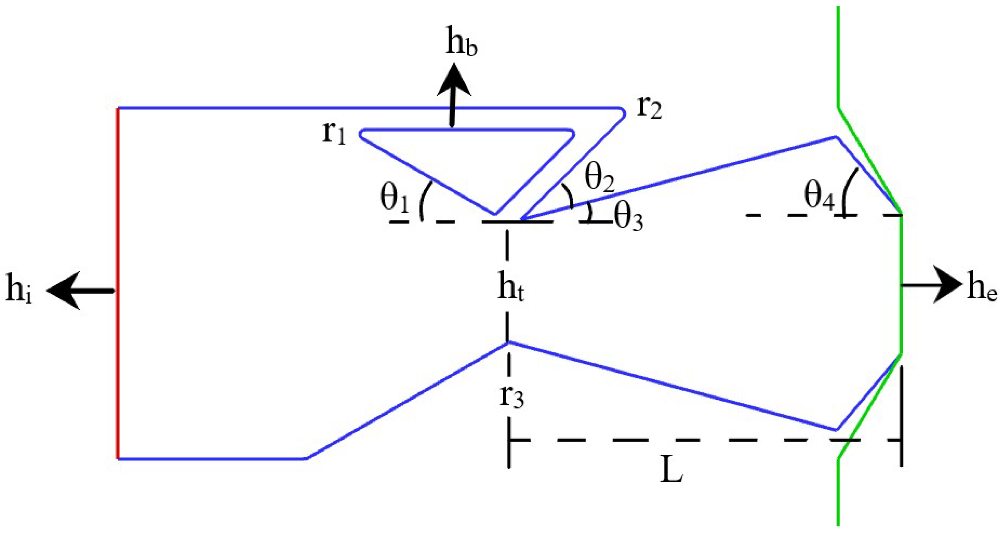
2. Proposed Nozzle Configuration

The geometry employed in this study is presented in Figure 1 and the baseline geometric parameters are presented in Table 1. The range for varied parameters is also mentioned in Table 2 where the nozzle convergence angle is varied from 30° to 37°, the bypass angle from 45° to 90°, and the ratio of bypass width to throat height (hb/ht) from 0.13 to 0.25. For NPR = 2–10, all these configurations are studied to investigate the thrust vectoring performance for under-expanded and over-expanded jets. A total of 160 simulation cases were conducted to analyze how these selected variables affected BDTN’s performance.

FTV Performance Parameters Considered

The performance parameters considered are thrust, discharge coefficients, vectoring angle and efficiency. Thrust vectoring parameter is calculated as [49],
δ = t a n 1 F N F A
F N and F A represents the normal and axial force, these forces are calculated as,
F A = ( ( ρ V x 2 ) + ( P e P b ) ) A 2 ,   F N = ( ρ V x V y ) A 2
V x and V y are the velocity in x and y direction. P b and P e are the back pressure and the exit pressure. The thrust coefficient parameter is calculated from the ratio of resultant thrust to the ideal thrust,
C f = F A 2 + F N 2 + F S 2 m ˙ a R T 0 2 γ γ 1 ( 1 ( ( P b P 0 ) γ 1 γ )
P b / P 0 is the NPR of the nozzle and F S represents the side force and is calculated as,
F s = ( ρ V x V z ) A 2
Discharge coefficient is calculated from the equation,
C d = m ˙ a P 0 A t R T 0 γ ( 2 γ + 1 ) γ + 1 2 ( γ 1 )
where m ˙ a is the actual mass flow rate and the vectoring efficiency is calculated as,
η = δ m ˙ p 100 m ˙ b
Here, m ˙ p and m ˙ s are the primary and secondary flow of the nozzle
m ˙ p = m ˙ b + m ˙ n
The primary flow of the nozzle is divided into a bypass and nozzle flow at the bypass entrance. The primary flow that passes through the bypass channel is denoted as m ˙ b while the rest of the air ( m ˙ n ) flows through the core nozzle.

3. Computational Method

3.1. Governing Equation

The present work involves solving 3D, steady, and compressible flow Navier–Stokes equations. We have ignored gravity effects. Turbulence modeling significantly affects the capture of shock boundary layers in nozzle flows [50,51,52]. A number of numerical models have been investigated for BDTN, which include Spalart–Allmaras, SST k-ω, and realizable k-ϵ turbulence models. As part of this study, RNG k-ϵ turbulence modeling was employed with standard wall functions. In addition, swirling flow parameters are incorporated into the RNG model, enhancing its accuracy. Due to the additional term in the ϵ equation, RNG k-ϵ improves the accuracy of the numerical model for strained flows. The coupled scheme with second-order upwind has been selected with a pseudo transient in this study. Numerical results indicate that the model is capable of resolving the detailed flow field, with the experimental results correlating well with the numerical results [40,41,42,43,44]. Hence, in this work, the governing equations are solved using ANSYS FLUENT along with the RNG k-ϵ turbulence model. The governing equations are:
Continuity Equation,
ρ t + x i ( ρ u i ) = 0
Momentum Equation,
t ( ρ u i ) + x j ( ρ u i u j ) = p x i + x i [ μ ( u i x j + u j x i 2 3 δ i j u k x k ) ] + x j ( ρ u i u j ¯ )
Energy Equation,
t ( ρ E ) + x i [ u i ( ρ E + p ) ] = x j [ ( k + C p μ t P r t ) + u i ( ρ u i u j ¯ ) ]
u j and ρ u i u j ¯ represents the fluctuating quantity and Reynolds stress tensor. The turbulence viscosity μ t is defined as:
μ t = ρ C μ k 2 ϵ
The transport equations are defined as:
t ( ρ k ) + x i ( ρ k u i ) = x i ( α k μ k x j ) + G k + G b ρ ϵ γ m + S k
And
t ( ρ ϵ ) + x i ( ρ ϵ u i ) = u i ( α k μ ε x j ) + C 1 e ϵ k ( G k + C 3 ϵ G b ) C 2 ϵ ρ ϵ 2 k R ϵ + S ϵ
Y m is the dilation dissipation term and is defined as:
Y m = 2 ρ ϵ M t 2
S e and S k are the user defined source terms. Where the values of C 1 ϵ , C 2 ϵ , C μ are
C 1 ϵ = 1.42 ,         C 2 ϵ = 1.68 ,         C μ = 0.0845
σ k and σ ϵ are the inverse effective Prandtl number for kinetic energy and dissipation rate.

3.2. Boundary Conditions

In the current study, ICEM is used to generate meshes for the BDTN computational domain presented in Figure 2 which is also discussed in the literature [49]. To ensure the accuracy of the results, the extended domain is created at the exit of the nozzle. The boundaries of the extended domain are represented as upstream, outlet, and side boundaries. The outlet and side boundaries are stretched by 16, 25, and 10 times the nozzle exit height in the x, y, and z axes, respectively. Pressure inlet boundary condition is applied at the nozzle inlet and pressure outlet is imposed on the downstream boundary of the domain. Similarly, far-field pressure is applied on the upstream boundary of the external domain. The no-slip and adiabatic boundary conditions are applied at the nozzle walls. Figure 2b illustrates the grid on the main nozzle. Depending on the design NPR, the total pressure varies as well, as P t =   P b × NPR. Pressure P b refers to atmospheric pressure.

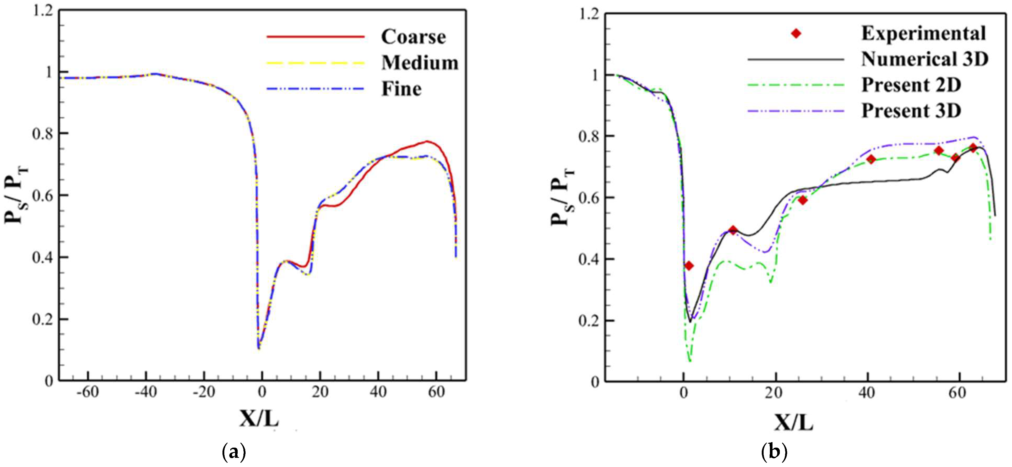
3.3. Grid Independence Test

Grid independence analysis is conducted to achieve higher accuracy results using high-density and high-resolution mesh. Three grids were generated: coarse, medium, and fine mesh, each containing 1,394,042, 2,897,622, and 4,837,092 quadrilateral cells, respectively. A minimum y+ = 5 value is selected for the meshes using grid stretching with 0.3 mm as the initial spacing. As per the Quality Metric Criteria, the minimum quality of mesh obtained is greater than 0.95. On all three grids, the static pressure distribution is monitored. The static pressure distribution for all three grids on the lower wall of the nozzle is presented in Figure 3a. In Figure 3a, the “0” location is the throat of the nozzle and the location after “0” provides the description of the shock position in the bottom wall of the nozzle to the nozzle’s exit. The results indicate the differential values in static pressure distribution for the coarse grid and the other two grids. However, static pressure distributions for medium and fine grids demonstrated a difference of 1%. As a result, the medium mesh was selected to conduct this study.

3.4. Computational Validation

This work compares computational with experimental data to validate the numerical method and the turbulence model. Our current study uses ANSYS ICEM CFD generated 3D computational domain at NPR = 3. The total pressure and temperature applied were 303,975 Pa and 300 K. Likewise, the inlet and back pressures were 303,975 Pa and 101,325 Pa. The static pressure distribution for the experimental and computational calculations on the nozzle wall is presented in Figure 3b. Based on the simulation results, the values match the experimental data with a maximum difference of 4.3%. The thrust vectoring angles and thrust coefficients for 2D and 3D models are also compared. The percentage error between the 2D models for thrust vectoring angle and thrust coefficient is presented in Table 3a. Similarly, the 3D model validation percentage error for NPR = 3, 5, and 10 are reported in Table 3b. All values are found to be in good agreement with the data of Rui Gu [40].

4. Results and Discussion

Three-dimensional numerical analysis is carried out to study the effect of nozzle convergence angle, bypass angle, and bypass width on the BDTN performance in the present study. Computational modeling and simulation of different configurations of BDTN were performed at NPR = 2–10 to predict the TV performance parameters.

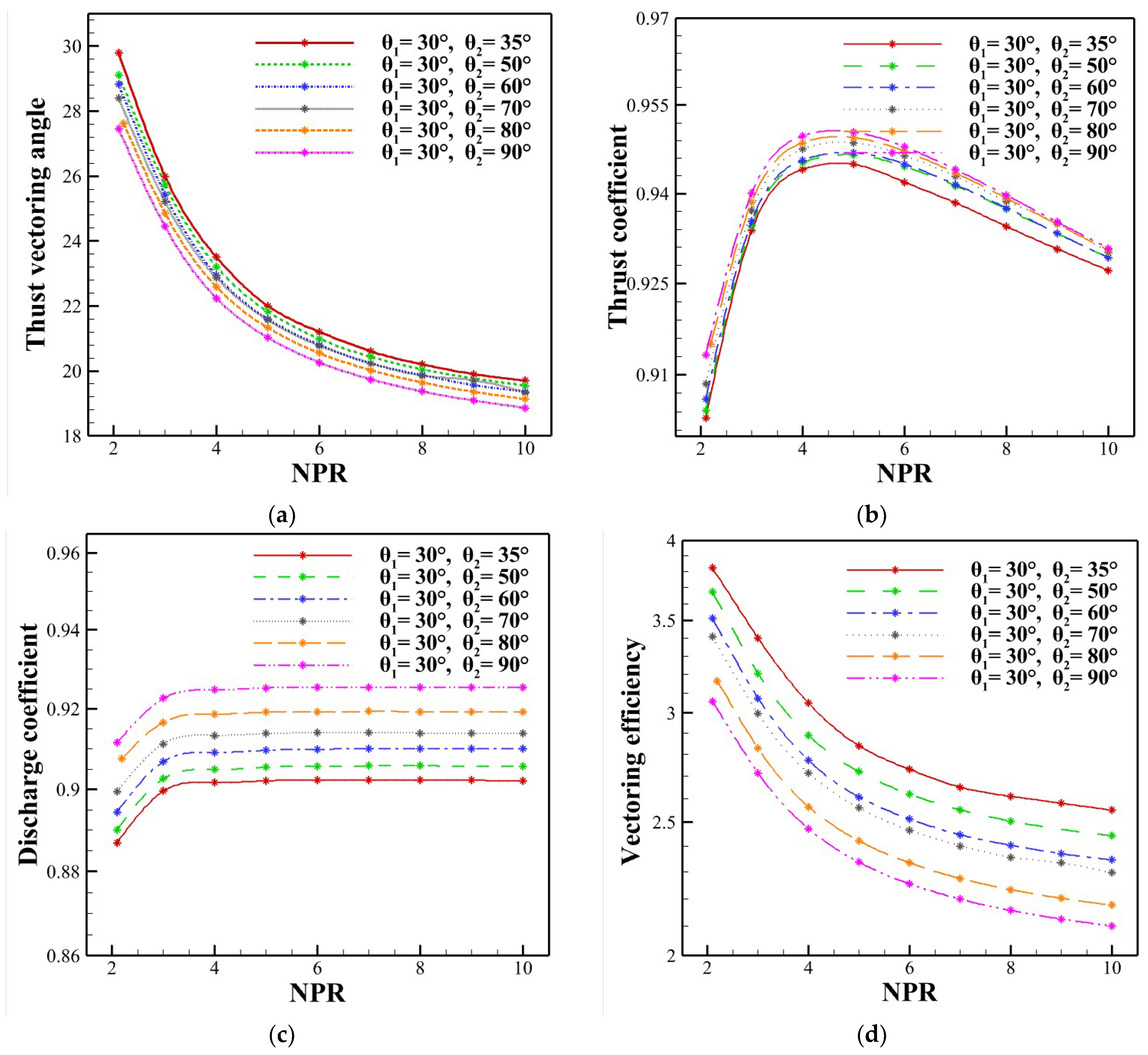
4.1. Effect of Bypass Angle and Bypass Width

In this section, the effect of bypass angle under different NPRs, the effect of bypass width, and the combined effect of bypass angle and bypass width on BDTN performance is discussed.

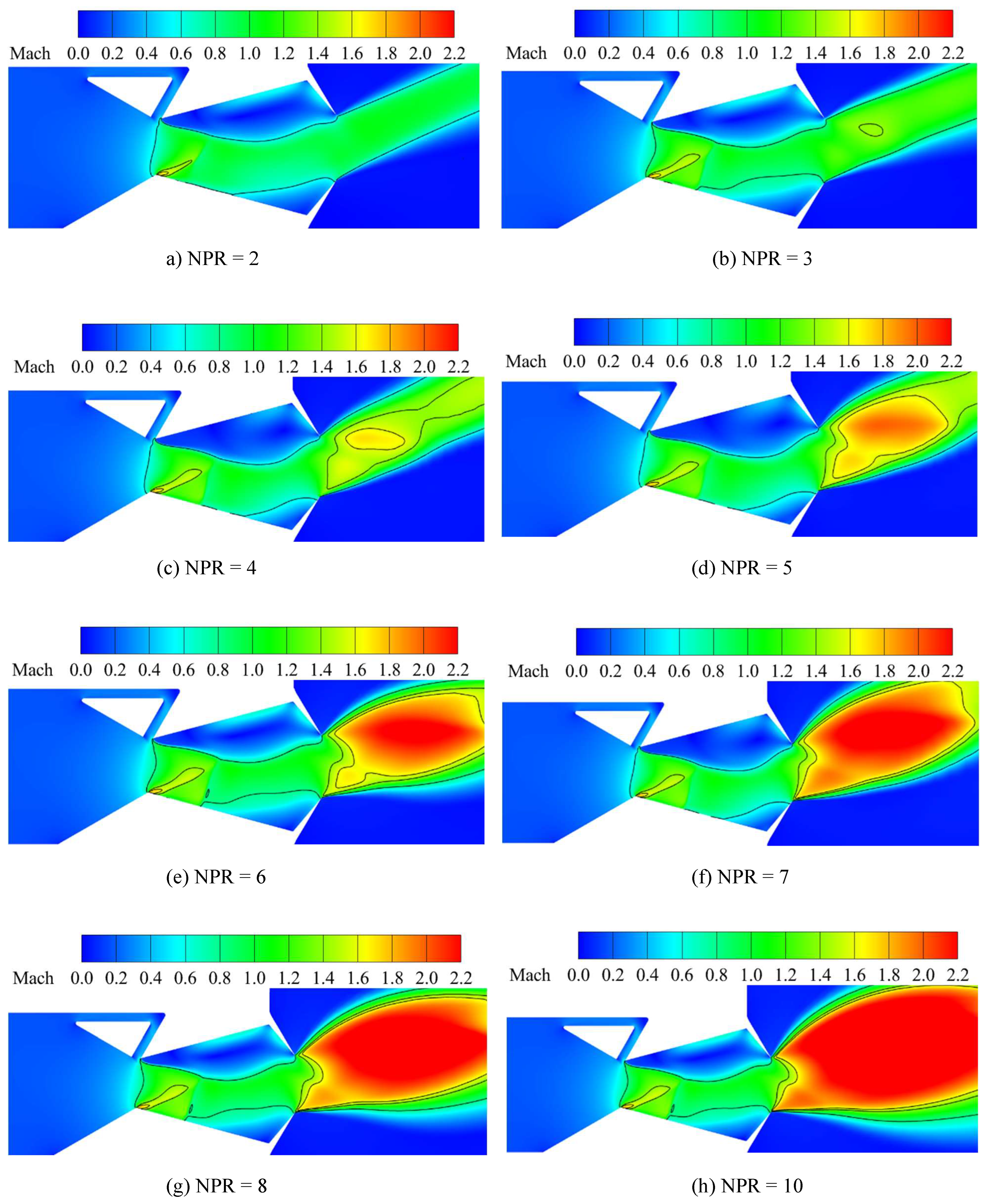
4.1.1. BDTN Performance under Different NPR

We investigated the effect of NPR on the performance of BDTN using simulations for θ 2 = 35–90° at NPR = 2–10. Figure 4 indicates the thrust vectoring performances for different configurations. The vectoring angle is decreased by increasing the NPR from 2 to 10 as shown in Figure 4a. The vectoring angle obtained for all models with NPR = 2 is greater than that obtained at NPR = 3–10. As NPR increases, the high-pressure flow behind the shock compresses the separation region in the cavity. The vortex in the separation region becomes smaller, leading to a weakening of jet deflection. In this way, the thrust vectoring angle decreases quickly for overexpanded conditions, while it decreases slowly for under expanded conditions. For selected NPRs, model 1 achieved the highest vectoring angle, while model 6 achieved the lowest values. Model 1 reported the maximum angle of 29.29° with NPR = 2. Figure 4b shows the trend for the thrust coefficient. Thrust coefficient increases for NPR < 5 and then decreases for NPR > 5. With increasing NPR, the supersonic region within the cavity expands due to the increase in the induced shock wave. The under-expanded state of the nozzle causes the supersonic region to increase, resulting in a decrease in the thrust coefficient. The thrust coefficient values of Model 6 are reported to be the highest. By increasing the bypass angle from 35° to 90°, the thrust coefficient is increased by about 1.5%. Figure 4c shows the predicted results of the effect of the bypass angle on the discharge coefficient. The discharge coefficient is independent of NPR as the flow in the nozzle is choked. The C d increases with increasing bypass angle from 35° to 90°. The discharge coefficient ranges from 0.88 to 0.91 for all configurations and is almost linear with NPR. A decreasing trend for vectoring efficiency was reported in Figure 4d as the NPR increases from 2 to 10. Among the 6 models, model 6 has the highest thrust efficiency of η = 3.72 at NPR = 2 and then drops to η = 2.39 at NPR = 10. Figure 5 represents the Mach contours for different NPR configurations. Due to the secondary flow interaction with the primary flow, normal and oblique shocks are formed in the cavity of the nozzle. The supersonic flow changes properties across normal shock and becomes subsonic. The vortex zone in the cavity reduces as the induced shock diminishes with increasing NPR. The vortex zone near the nozzle exit increases with initial NPR and decreases with increasing NPR. By expanding and deflecting the primary flow, the subsonic flow generates thrust vectoring angles. Figure 6 represents the 3D streak lines at NPR = 3, 5, 7, and 9. A vortex forms at the upper cavity wall. At NPR = 2, the highest efficiency of the vortex is produced, which results in a higher vectoring angle. By increasing the NPR, the efficiency of the vortex decreases, thereby reducing the vectoring angle. Figure 7 shows the Mach contours on different X/L planes for NPR = 9. The left side plane contours in the nozzle indicate the subsonic flow in the convergent region. The planes in the cavity region of the nozzle indicate that the supersonic flow is established as the flow accelerates. As the flow predominantly remains symmetric, hence, the 3D effect is not significant.

4.1.2. BDTN Performance under Different Bypass Width

Figure 8 indicates the thrust vectoring performances for different bypass width configurations. According to Figure 8a, the thrust vectoring angle increased as the bypass width increased. The bypass flow becomes stronger with a higher bypass width, resulting in a higher vectoring angle. In this study, the maximum value of vectoring angle at   h b = 5 mm for bypass flow of 8.59% over the primary mass flow is recorded for model 1. Model 1 has the highest vectoring angle, whereas model 6 achieved the lowest vectoring angle for each bypass width. A total decrease of 7% in vectoring angle is reported from model 1 to model 6. Flow separation is enhanced when the bypass outlet increases with increasing bypass width. This enhanced separation flow region results in a smaller local supersonic region within the cavity. Therefore, as shown in Figure 8b, the thrust coefficient decreases with increasing bypass width. The discharge coefficient starts to decrease with increasing bypass width, as shown in Figure 8c. Thrust vectoring efficiency follows a similar trend in Figure 8d. The efficiency decreases with increasing bypass width for each configuration. The efficiency is decreased by about 17%, 14%, 16%, 15%, and 20% from model 1 to model 6 for the selected bypass width. Figure 9 represents the Mach contours on different bypass widths for model 3. At the nozzle exit, lower bypass widths result in higher static pressure, while higher bypass widths result in lower static pressure. Higher static pressure and lower bypass width tend to cause the thrust vectoring angle to decrease while vectoring efficiency, discharge, and thrust coefficient increase is increased.
As shown in Figure 9a, due to the decrease in the bypass cross-sectional area ( h b = 2.6 mm) lower vectoring angle is achieved. Higher vectoring angles were reported for increasing bypass width. Moreover, for a particular bypass width, increasing the bypass angle decreases thrust vectoring angle but the thrust coefficient increases. In addition to a 4% increase in vectoring angle, a 19%, 0.9%, and 0.1% decrease in vectoring efficiency, discharge, and thrust coefficient were observed with an increase in bypass width.

4.1.3. Combined Effect of Bypass Width and Bypass Angle

The effect of bypass width and bypass angle on the vectoring performance of BDTN is investigated. Figure 10a represents the vectoring angle and efficiency obtained for θ 2 = 35–90°and hb = 2–5 mm. Increasing the bypass angle and decreasing the bypass width resulted in a decrease in vectoring angle. At h b = 5 mm, Model 1 had the highest vectoring angle. With hb = 2.6 mm, model 6 showed the lowest vectoring angle. Vectoring efficiency, on the other hand, revealed a decreasing trend. Model 6 with h b = 5 mm showed the lowest vectoring efficiency, while model 1 with h b = 2.6 mm showed the highest. The thrust and discharge coefficients for θ 2 = 35–90° and h b = 2–5 mm are presented in Figure 10b. As the bypass angle and width increase the thrust coefficient decreases. Among the models analyzed, model 6 achieved the highest thrust coefficient with h b = 2.6 mm, while model 1 with h b = 5 mm achieved the lowest thrust coefficient value. The discharge coefficient shows a similar trend. Increasing the bypass width along with bypass angle resulted in decreasing discharge coefficient with highest values found at 2.6 mm, while minimum values at the bypass width of 5 mm. Among all the investigated models, model 6 achieved the highest discharge coefficient at h b = 2.6 mm, and model 1 reported the lowest discharge coefficient with h b = 5 mm.

4.2. Effect of Nozzle Convergence Angle and Bypass Width

In this section, the effect of nozzle convergence angle under different NPRs, the effect of bypass width, and the combined effect of convergence angle and bypass width on BDTN performance is discussed.

4.2.1. BDTN Performance under Different NPR

To investigate the performance of the nozzle convergence angle, the convergence angle (θ1) is varied from 22° to 37° for NPR = 2–10 at a constant width ratio of 0.185. Figure 11a depicts the thrust vectoring angles for different configurations at different NPR. Increasing the nozzle convergence angle from 22° to 37° decreases the vectoring angle. The vectoring angles obtained for all models under NPR = 2 was higher than those obtained at NPR = 3–10. Of all the investigated models, model 7 produced the highest vectoring angle. A 1.5% difference in vectoring angle was reported with changing the convergence angle from 22° to 37°. Therefore, the vectoring angle was not significantly affected by the nozzle convergence angle. As illustrated in Figure 11d, vectoring efficiency also shows a similar pattern. Model 7 has the highest vectoring efficiency of 3.87, whereas model 11 has the lowest vectoring efficiency of 2.31. Model 7 has the overall best vectoring efficiency among the other models. Figure 11b shows the thrust obtained for different convergence angles. Among the other models, model 7 reported the highest thrust coefficient of 0.948 at NPR = 5. In Figure 11c, the discharge coefficient increases till NPR = 4 and remains almost linear with further increasing the NPR. Model 7 reported higher discharge coefficient values. Figure 12 shows the Mach contours for the nozzle convergence angle configuration for NPR = 4, 6, 8, and 10.

4.2.2. BDTN Performance under Different Bypass Width

Figure 13 represents the vectoring performance of BDTN for different configurations of bypass width at NPR = 3. The obtained thrust vectoring angle for the bypass width configurations is shown in Figure 13a. According to the result, the vectoring angle increases as bypass width increases for all models. The bypass flow becomes stronger with a higher bypass width, resulting in a higher vectoring angle. Moreover, with increasing the nozzle converging angle, the vectoring angle increases, however, other performance parameters decrease. The highest vectoring angles were recorded by model 11, while the lowest was recorded by model 7.
From model 7 to model 11, a decrease of 1.81% was reported for thrust vectoring angle. As shown in Figure 13b, the thrust coefficient decays with increasing bypass width. Flow separation is enhanced when the bypass width increases. This enhanced separation flow region results in the smaller local supersonic region within the cavity. Therefore, the thrust coefficient decreases with increasing the bypass width. The discharge coefficient has a decreasing trend with increasing bypass width, as shown in Figure 13c. The discharge coefficient is decreased from 1.84% to 1.27% from model 7 to model 11. Thrust vectoring efficiency follows a similar trend. The efficiency decreases with increasing bypass width for each configuration. The efficiency is decreased by 22.2%, 20.8%, 18.6%, 23.2%, and 17% from model 7 to model 11 for the selected bypass width.

4.2.3. Combined Effect of Bypass Width and Nozzle Convergence Angle

The effect of bypass width and convergence angle on the vectoring performance of BDTN is investigated. Figure 14a represents the vectoring angle and efficiency obtained for   θ 1 = 22–37° and h b = 2–5 mm. Vectoring angle revealed an increasing trend with increasing the convergence angle and decreasing the bypass width. At h b = 5 mm, Model 11 has the highest vectoring angle while model 7 showed the lowest vectoring angle. Vectoring efficiency has a decreasing trend with convergence angle. Model 11 with   h b = 5 mm showed the lowest vectoring efficiency, while model 7 with h b = 2.6 mm has the highest. According to Figure 14b, with increasing bypass width and convergence angle the thrust coefficient is decreased. Among the investigated models, model 7 achieved the highest thrust coefficient with h b = 2.6 mm, while model 11 with h b = 5 mm achieved the lowest thrust coefficient value. The discharge coefficient shows a similar trend. Increasing the bypass width along with the convergence angle resulted in decreasing discharge coefficient.

5. Conclusions

This study numerically investigates the performance of BDTN at different NPR. Three geometric parameters are analyzed to study the effect of thrust vectoring. The main conclusions of this study are as follows.
  • NPR significantly affects the thrust vectoring performance of BDTN. As NPR increases, the squeezing effect of the vortex in the cavity reduces, which reduces the supersonic region within the nozzle. Because the vortex size and supersonic region are reduced, BDTN has a lower thrust vectoring performance.
  • As bypass width influences vectoring angle, increasing bypass width increases the vectoring angle due to increased mass flow. However, a reduction in vectoring efficiency, thrust, and discharge coefficient is obtained to reach a higher vectoring angle. It is found that a bypass width of 3.7 mm is an optimal choice for effective vectoring performance.
  • The bypass angle is an important factor in generating effective vectoring angles. Increasing the bypass angle and decreasing the bypass width resulted in an increase in the thrust and discharge coefficient and a decrease in vectoring angle. Optimal vectoring performance is achieved with a bypass angle of 35°.
  • BDTN’s performance is not significantly affected by nozzle convergence angle. An increase of 1.5% in vectoring performance is obtained with increasing convergence angle. Increasing the convergence angle and bypass width increases the vectoring angle while decreases the vectoring efficiency, thrust, and discharge coefficient of the nozzle.

Author Contributions

Conceptualization, T.A.K. and S.I.A.S.; methodology, S.A.; software, S.A.; Validation, S.A.; Formal analysis, S.A. and T.A.S.; Investigation, S.A.; Resources, W.L.; Writing—original draft, S.A.; Writing—review & editing, T.A.K. and K.M.; Project administration, D.K.; funding acquisition, D.K. All authors have read and agreed to the published version of the manuscript.

Funding

This research received no external funding. The APC was funded by Prof. David Kukulka.

Institutional Review Board Statement

Not applicable.

Informed Consent Statement

Not applicable.

Data Availability Statement

All data, models, or code that support the findings of this study are available from the corresponding author upon reasonable request.

Conflicts of Interest

The authors declare no conflict of interest.

Nomenclature

δThrust vectoring angle
m p Primary mass flow
C d Discharge coefficient
C f Thrust coefficient
ηThrust vectoring efficiency
F A Axial force
F N Normal force
F S Side force
P 0 Stagnation pressure
P e Exit pressure
P s Static Pressure
P t Total pressure
T 0 Stagnation temperature
T t Total temperature
FTVFluidic thrust vectoring
MTV Mechanical thrust vectoring
BDTNBypass dual throat
DTN Dual throat nozzle
NPRNozzle pressure ratio
SVCShock vector control
TSCThroat skewing control
CFTVCounter flow thrust vectoring
RNGRenormalization group
SPRSecondary pressure ratio

References

  1. Ross, H.; Huber, P. Application of thrust vectoring to future aircraft design. In Proceedings of the Advanced Aero-Engine Concepts and Controls, Seattle, WA, USA, 25–29 September 1995; 21/1–21/10. Deutsche Aerospace AG: Seattle, WA, USA. [Google Scholar]
  2. Herbst, W. Future fighter technologies. J. Aircr. 1980, 17, 561–566. [Google Scholar] [CrossRef]
  3. Mace, J.; Smereczniak, P.; Krekeler, G.; Bowers, D.; Maclean, M. Advanced thrust vectoring nozzles for supercruise fighter aircraft. In Proceedings of the 25th Joint Propulsion Conference, Monterey, CA, USA, 12–16 July 1989. [Google Scholar] [CrossRef]
  4. Forghany, F.; Taeibe-Rahni, M.; Asadollahi-Ghohieh, A.; Banazdeh, A. Numerical investigation of injection angle effects on shock vector control performance. Proc. Inst. Mech. Eng. Part G J. Aerosp. Eng. 2017, 233, 405–417. [Google Scholar] [CrossRef]
  5. Li, L.; Saito, T. Numerical and Experimental Investigations of Fluidic Thrust Vectoring Mechanism. Int. J. Aerosp. Innov. 2012, 4, 53–64. [Google Scholar] [CrossRef]
  6. Ferlauto, M.; Marsilio, R. Computational Investigation of Injection Effects on Shock Vector Control Performance. In Proceedings of the 2018 Joint Propulsion Conference, Cincinnati, OH, USA, 9–11 July 2018. [Google Scholar] [CrossRef]
  7. Deng, R.; Kong, F.; Kim, H.D. Numerical simulation of fluidic thrust vectoring in an axisymmetric supersonic nozzle. J. Mech. Sci. Technol. 2014, 28, 4979–4987. [Google Scholar] [CrossRef]
  8. Spaid, F.W.; Zukoski, E.E. A study of the interaction of gaseous jets from transverse slots with supersonic external flows. AIAA J. 1968, 6, 205–212. [Google Scholar] [CrossRef]
  9. Guhse, R.D. On secondary gas injection in supersonic nozzles. J. Spacecr. Rocket. 1966, 3, 147–149. [Google Scholar] [CrossRef]
  10. Shi, J.W.; Wang, Z.X.; Zhou, L. Numerical Investigation on Flow Fields of SVC Nozzle with Bypass Injection. J. Phys. Conf. Ser. 2019, 1215, 012038. [Google Scholar] [CrossRef]
  11. Islam, M.S.; Hasan, M.A.; Hasan, A.T. An analysis of thrust vectoring in a supersonic nozzle using bypass mass injection. AIP Conf. Proc. 2018, 1980, 040014. [Google Scholar]
  12. Nafi, M.A.; Hasan, A.B.M.T. 3D computational study of thrust vectoring using bypass mass injection in a propulsion nozzle. AIP Conf. Proc. 2019, 2121, 050013. [Google Scholar] [CrossRef]
  13. Li, L.; Hirota, M.; Ouchi, K.; Saito, T. Evaluation of fluidic thrust vectoring nozzle via thrust pitching angle and thrust pitching moment. Shock. Waves 2016, 27, 53–61. [Google Scholar] [CrossRef]
  14. Deng, R.; Kim, H.D. A study on the thrust vector control using a bypass flow passage. Proc. Inst. Mech. Eng. Part G. J. Aerosp. Eng. 2015, 229, 1722–1729. [Google Scholar] [CrossRef]
  15. Viti, V.; Neel, R.; Schetz, J.A. Detailed flow physics of the supersonic jet interaction flow field. Phys. Fluids 2009, 21, 046101. [Google Scholar] [CrossRef]
  16. AlAsadi, A.A.H.; Faseeh, A.H. Fluidics jet vectoring for incompressible flow by using counter flow method for circular duct. Al-Nahrain J. Eng. Sci. 2017, 20, 911–923. [Google Scholar]
  17. Wu, K.; Zhang, G.; Kim, T.H.; Kim, H.D. Numerical parametric study on three-dimensional rectangular counter-flow thrust vectoring control. Proc. Inst. Mech. Eng. Part G J. Aerosp. Eng. 2020, 234, 2221–2247. [Google Scholar] [CrossRef]
  18. Wu, K.; Kim, H.D.; Jin, Y. Fluidic thrust vector control based on counter-flow concept. Proc. Inst. Mech. Eng. Part G J. Aerosp. Eng. 2019, 233, 1412–1422. [Google Scholar] [CrossRef]
  19. Jun, L.; Wei, L.; Yuncheng, W.; Yonglei, Z. Improved design and performance analysis of counterflow thrust vectoring technology under high subsonic. J. Intell. Fuzzy Syst. 2018, 34, 1213–1223. [Google Scholar] [CrossRef]
  20. Banazadeh, A.; Saghafi, F.; Ghoreyshi, M.; Pilidis, P. Experimental and computational investigation into the use of co-flow fluidic thrust vectoring on a small gas turbine. Aeronaut. J. 2008, 112, 17–25. [Google Scholar] [CrossRef]
  21. Al-Asady, A.A.A.; Abdullah, A.M. Fluidics thrust vectoring using co-flow method. Al-Nahrain J. Eng. Sci. 2017, 20, 5–18. [Google Scholar]
  22. Mason, M.; Crowther, W. Fluidic Thrust Vectoring for Low Observable Air Vehicles. In Proceedings of the 2nd AIAA Flow Control Conference, Portland, OR, USA, 28 June–1 July 2004. [Google Scholar] [CrossRef]
  23. Chiarelli, C.; Johnsen, R.; Shieh, C.; Wing, D. Fluidic scale model multi-plane thrust vector control test results. In Proceedings of the 29th Joint Propulsion Conference and Exhibit, Monterey, CA, USA, 28–30 June 1993. [Google Scholar] [CrossRef]
  24. Wu, K.; Jin, Y.; Kim, H.D. Hysteretic Behaviors in Counter-Flow Thrust Vector Control. J. Aerosp. Eng. 2019, 32, 1–9. [Google Scholar] [CrossRef]
  25. Banazadeh, A.; Saghafi, F. An investigation of empirical formulation and design optimisation of co-flow fluidic thrust vectoring nozzles. Aeronaut. J. 2016, 121, 213–236. [Google Scholar] [CrossRef]
  26. Yagle, P.J.; Miller, D.N.; Ginn, K.B.; Hamstra, J.W. Demonstration of Fluidic Throat Skewing for Thrust Vectoring in Structurally Fixed Nozzles. J. Eng. Gas Turbines Power 2001, 123, 502–507. [Google Scholar] [CrossRef]
  27. Wing, D.J. Static Performance Investigation of a Skewed-Throat Multiaxis Thrust-Vectoring Nozzle Concept; National Aeronautics and Space Administration, Langley Research Center: Hampton, VA, USA, 1994; Volume 3411. [Google Scholar]
  28. Ali, A.; Rodriguez, C.; Neely, A.; Young, J. Combination of Fluidic Thrust Modulation and Vectoring in a 2D Nozzle. In Proceedings of the 48th AIAA/ASME/SAE/ASEE Joint Propulsion Conference & Exhibit, Atlanta, GA, USA, 30 July–1 August 2012. [Google Scholar] [CrossRef]
  29. Williams, R.; Vittal, B. Fluidic thrust vectoring and throat control exhaust nozzle. In Proceedings of the 38th AIAA/ASME/SAE/ASEE Joint Propulsion Conference & Exhibit, Indianapolis, IN, USA, 7–10 July 2002; p. 4060. [Google Scholar]
  30. Miller, D.; Yagle, P.; Hamstra, J. Fluidic throat skewing for thrust vectoring in fixed-geometry nozzles. In Proceedings of the 37th Aerospace Sciences Meeting and Exhibit, Reno, NV, USA, 11–14 January 1999. [Google Scholar] [CrossRef]
  31. Wu, K.; Kim, T.; Kim, H. Numerical study of fluidic thrust vector control using dual throat nozzle. J. Appl. Fluid Mech. 2021, 14, 73–87. [Google Scholar]
  32. Shin, C.S.; Kim, H.; Setoguchi, T.; Matsuo, S. A computational study of thrust vectoring control using dual throat nozzle. J. Therm. Sci. 2010, 19, 486–490. [Google Scholar] [CrossRef]
  33. Deere, K.; Berrier, B.; Flamm, J.; Johnson, S. Computational Study of Fluidic Thrust Vectoring Using Separation Control in a Nozzle. In Proceedings of the 21st AIAA Applied Aerodynamics Conference, Orlando, FL, USA, 23–26 June 2003. [Google Scholar] [CrossRef]
  34. Deere, K.; Berrier, B.; Flamm, J.; Johnson, S. A Computational Study of a Dual Throat Fluidic Thrust Vectoring Nozzle Concept. In Proceedings of the 41st AIAA/ASME/SAE/ASEE Joint Propulsion Conference & Exhibit, Tucson, AZ, USA, 10–13 July 2005. [Google Scholar] [CrossRef]
  35. Flamm, J.; Deere, K.; Berrier, B.; Johnson, S.; Mason, M. Experimental Study of a Dual-Throat Fluidic Thrust-Vectoring Nozzle Concept. In Proceedings of the 41st AIAA/ASME/SAE/ASEE Joint Propulsion Conference & Exhibit, Tucson, AZ, USA, 10–13 July 2005. [Google Scholar] [CrossRef]
  36. Ferlauto, M.; Marsilio, R. Numerical simulation of fluidic thrust-vectoring. Aerotec. Missili Spaz. 2016, 95, 153–162. [Google Scholar] [CrossRef] [Green Version]
  37. Wu, K.; Kim, H.D. Study on fluidic thrust vector control based on dual-throat concept. J. Korean Soc. Propuls. Eng. 2019, 23, 24–32. [Google Scholar] [CrossRef]
  38. Ferlauto, M.; Marsilio, R. Numerical Investigation of the Dynamic Characteristics of a Dual-Throat-Nozzle for Fluidic Thrust-Vectoring. AIAA J. 2017, 55, 86–98. [Google Scholar] [CrossRef]
  39. Deere, K.; Flamm, J.; Berrier, B.; Johnson, S. Computational Study of an Axisymmetric Dual Throat Fluidic Thrust Vectoring Nozzle for a Supersonic Aircraft Application. In Proceedings of the 43rd AIAA/ASME/SAE/ASEE Joint Propulsion Conference & Exhibit, Cincinnati, OH, USA, 8–11 July 2007. [Google Scholar] [CrossRef] [Green Version]
  40. Gu, R.; Xu, J.; Guo, S. Experimental and numerical investigations of a bypass dual throat nozzle. J. Eng. Gas Turbines Power August 2014, 136, 084501. [Google Scholar] [CrossRef]
  41. Hamedi-Estakhrsar, M.H.; Mahdavy-Moghaddam, H. Experimental evaluation and numerical simulation of performance of the bypass dual throat nozzle. Proc. Inst. Mech. Eng. Part G J. Aerosp. Eng. 2020, 235, 768–781. [Google Scholar] [CrossRef]
  42. Hamedi-Estakhrsar, M.; Ferlauto, M.; Mahdavy-Moghaddam, H. Numerical study of secondary mass flow modulation in a Bypass Dual-Throat Nozzle. Proc. Inst. Mech. Eng. Part G J. Aerosp. Eng. 2020, 235, 488–500. [Google Scholar] [CrossRef]
  43. Wang, Y.; Xu, J.; Huang, S.; Lin, Y.; Jiang, J. Computational study of axisymmetric divergent bypass dual throat nozzle. Aerosp. Sci. Technol. 2019, 86, 177–190. [Google Scholar] [CrossRef]
  44. Wang, Y.; Xu, J.; Huang, S.; Jiang, J.; Pan, R. Design and Preliminary Analysis of the Variable Axisymmetric Divergent Bypass Dual Throat Nozzle. J. Fluids Eng. 2020, 142, 061204. [Google Scholar] [CrossRef]
  45. Wu, K.; Kim, H. A fluidic thrust vector control using the bypass flow in a dual throat nozzle. J. Mech. Sci. Technol. 2021, 35, 3435–3443. [Google Scholar] [CrossRef]
  46. Huang, S.; Xu, J.; Yu, K.; Wang, Y.; Pan, R. Design and experimental study of a bypass dual throat nozzle with the ability of short/vertical takeoff and landing. Aerosp. Sci. Technol. 2021, 121, 107301. [Google Scholar] [CrossRef]
  47. Shi, L.; Yang, G.; Yao, S. Large eddy simulation of flow past a square cylinder with rounded leading corners: A comparison of 2D and 3D approaches. J. Mech. Sci. Technol. 2018, 32, 2671–2680. [Google Scholar] [CrossRef]
  48. Cravero, C.; Marogna, N.; Marsano, D. A Numerical Study of Correlation Between Recirculation Length and Shedding Frequency in Vortex Shedding Phenomena. WSEAS Trans. Fluid Mech. 2021, 16, 48–62. [Google Scholar] [CrossRef]
  49. Afridi, S.; Khan, T.A. Multi-objective nozzle design optimization for maximum thrust vectoring performance. Proc. Inst. Mech. Eng. Part G J. Aerosp. Eng. 2022. [Google Scholar] [CrossRef]
  50. Tian, C.; Lu, Y. Turbulence Models of Separated Flow in Shock Wave Thrust Vector Nozzle. Eng. Appl. Comput. Fluid Mech. 2013, 7, 182–192. [Google Scholar] [CrossRef] [Green Version]
  51. Chaudhuri, A.; Hadjadj, A. Numerical investigations of transient nozzle flow separation. Aerosp. Sci. Technol. 2016, 53, 10–21. [Google Scholar] [CrossRef]
  52. Yaravintelimath, A.; Raghunandan, B.; Morinigo, A. Numerical prediction of nozzle flow separation: Issue of turbulence modeling. Aerosp. Sci. Technol. 2016, 50, 31–43. [Google Scholar] [CrossRef]
Figure 1. Configuration of BDTN.
Energies 16 00594 g001
Figure 2. (a) Computational domain and boundary conditions (b) The mesh on the rectangular nozzle.
Energies 16 00594 g002
Figure 3. Plot (a) static pressure distribution for all three grids. (b) comparing static pressure distribution for the experimental and computational calculations at NPR = 3.
Energies 16 00594 g003
Figure 4. Variation of (a) the vectoring angle, (b) thrust coefficient, (c) discharge coefficient, and (d) vectoring efficiency with NPR for h b / h t = 0.185.
Energies 16 00594 g004
Figure 5. Mach contours at θ 2 = 50°, θ 1 = 30° and h b / h t = 0.185 for different NPR.
Energies 16 00594 g005
Figure 6. Vortex formation at the upper cavity wall at θ 2 = 50°, θ 1 = 30° and h b / h t = 0.185 for (a) NPR = 3 (b) NPR = 5 (c) NPR = 7 (d) NPR = 10.
Energies 16 00594 g006
Figure 7. Mach contours obtained for different X/L planes.
Energies 16 00594 g007
Figure 8. Variation of (a) vectoring angle, (b) thrust coefficient, (c) discharge coefficient, and (d) the vectoring efficiency for NPR = 3.
Energies 16 00594 g008
Figure 9. Mach contours on the center-plane at NPR = 3, θ 2 = 70° and θ 1 = 30° for bypass width of (a) 2.7 mm (b) 3.2 mm (c) 3.7 mm (d) 4.2 mm (e) 5 mm.
Energies 16 00594 g009
Figure 10. The variation of (a) vectoring angle and vectoring efficiency (b) thrust coefficient and discharge coefficient with bypass angle.
Energies 16 00594 g010
Figure 11. Plotting of (a) vectoring angle, (b) thrust coefficient, (c) discharge coefficient, and (d) vectoring efficiency for h b / h t = 0.185.
Energies 16 00594 g011
Figure 12. This represents the Mach contours at θ 1 = 25°, θ 2 = 45°, and h b / h t = 0.185 for different NPR.
Energies 16 00594 g012
Figure 13. Variation of (a) the vectoring angle, (b) thrust coefficient, (c) discharge coefficient, and (d) vectoring efficiency with increasing bypass width at NPR = 3.
Energies 16 00594 g013aEnergies 16 00594 g013b
Figure 14. (a) refers to the trend of vectoring angle and vectoring efficiency. (b) refers to the trend of thrust and discharge coefficient with nozzle convergence angle.
Energies 16 00594 g014
Table 1. The constant geometric dimensions and parameters adopted from Rui Gu [40].
ParametersDimensions
Cavity divergence angle θ 3 15°
Cavity convergence angle θ 4 50°
Inlet height h i 60 mm
Throat height h t 20 mm
Exit height h e 24 mm
Radius r 1 0.8 mm
Radius r 2 1 mm
Radius r 3 0.3 mm
Length of cavity L66.8 mm
Table 2. Models are based on the variation in bypass width.
Model θ 1 θ 2 h b / h t
130°35°0.13–0.25
230°50°0.13–0.25
330°60°0.13–0.25
430°70°0.13–0.25
530°80°0.13–0.25
630°90°0.13–0.25
722°45°0.13–0.25
825°45°0.13–0.25
927°45°0.13–0.25
1032°45°0.13–0.25
1137°45°0.13–0.25
Table 3. (a) 2D model validation percentage error for various NPR values. (b) 3D model validation percentage error for NPR = 3, 5, and 10.
(a)
NPRRui Gu [40]Present DataPercentage Error
δCfδCfδCf
232.02°0.93331.8°0.9120.68%2.25%
327.21°0.95927.15°0.940.22%1.98%
424.52°0.96524.3°0.950.90%1.55%
523.12°0.96322.9°0.9510.95%1.25%
622.54°0.96 22.13°0.9481.82%1.25%
722.09°0.95521.6°0.9462.22%0.94%
821.71°0.9521.2°0.9422.35%0.84%
(b)
NPRRui Gu [40]Present DataPercentage Error
δCfδCfδCf
326.95°0.94925.78°0.9344.32%1.61%
521.08°0.95621.02°0.9460.28%1.01%
1020.27°0.93419.52°0.9233.70%1.17%
Disclaimer/Publisher’s Note: The statements, opinions and data contained in all publications are solely those of the individual author(s) and contributor(s) and not of MDPI and/or the editor(s). MDPI and/or the editor(s) disclaim responsibility for any injury to people or property resulting from any ideas, methods, instructions or products referred to in the content.

