Article

Optimal Design of Corona Ring for 132 kV Insulator at High Voltage Transmission Lines Based on Optimisation Techniques

by
Kalaiselvi Aramugam
1,
Hazlee Azil Illias
1,*,
Yern Chee Ching
2,
Mohd Syukri Ali
3 and
Mohamad Zul Hilmey Makmud
4,*
1
Department of Electrical Engineering, Faculty of Engineering, Universiti Malaya, Kuala Lumpur 50603, Malaysia
2
Department of Chemical Engineering, Faculty of Engineering, Universiti Malaya, Kuala Lumpur 50603, Malaysia
3
Higher Institution Centre of Excellence (HICoE), UM Power Energy Dedicated Advanced Centre (UMPEDAC), Level 4, Wisma R&D, University of Malaya, Jalan Pantai Baharu, Kuala Lumpur 59990, Malaysia
4
Faculty of Science and Natural Resources, Universiti Malaysia Sabah, Kota Kinabalu 88400, Sabah, Malaysia
*
Authors to whom correspondence should be addressed.
Energies 2023, 16(2), 778; https://doi.org/10.3390/en16020778
Submission received: 20 October 2022 / Revised: 9 November 2022 / Accepted: 23 November 2022 / Published: 9 January 2023
(This article belongs to the Topic High Voltage Engineering)

Abstract

:
The installation of a corona ring on an insulator string on a transmission line is one of the solutions to reduce the electric field stress surrounding the energised end of the insulator string. However, installing a corona ring with an optimum design to reduce the electric field magnitude on an insulator string is a challenging task. Therefore, in this work, a method to achieve the optimum design of a corona ring for 132 kV composite non-ceramic insulator string was proposed using two optimisation methods: the Imperialist Competitive Algorithm (ICA) and Grey Wolf Optimisation (GWO). A composite non-ceramic insulator string geometry with and without a corona ring was modelled in finite element analysis and used to obtain the electric field distribution in the model geometry. The electric field distribution was evaluated using a variation in the corona ring’s dimensions, i.e., the ring diameter, the ring tube diameter and the vertical position of the ring along the insulator string. From the results achieved, a comparison of the minimum electric field magnitude along the insulator string with a corona ring design shows that the minimum electric field magnitude is found to be lower using optimisation techniques compared to without using optimisation techniques by between 3.724% and 3.827%. Hence, this indicates the capability and effectiveness of the proposed methods in achieving the optimum design of a corona ring on an insulator string.

1. Introduction

A composite insulator plays the main role in a transmission line system. Insulators give a better mechanical incentive to conductors and also lower the discharge of the current that flows from the conductor to the earth [1]. The insulators used for the suspension of overhead transmission lines act as flashover effects. An insulation failure and loss of hydrophobicity could occur when the surface of the insulator is exposed to extremely high electric fields. All these problems occur due to the non-uniform distribution of the electric field along the insulator. An uneven electric field distribution tends to increase the electric field magnitude near the phase terminal [2]. The critical problem found by outdoor high voltage insulators is partial discharge (PD). PDs happen within a large electric field region on the insulation surface and at the end of an insulator [1,3].
The earth and high voltage capacitances are the main influence of the distribution of an electric field on the composite insulator surface [4,5]. Capacitors are installed between each of the insulators with respect to the high voltage conductor and earth, which yields an uneven electric field distribution and potential distribution on the surface of the insulator string. Insulators have a high stress and a more uneven potential distribution when they are nearer to the conductors.
A non-ceramic insulator has been widely adopted in recent transmission line systems. It being of a light weight, its pollution performance and its mechanical impact to reduce the size of transmission lines are some of the advantages that can be found in non-ceramic insulators. However, non-ceramic insulators face the aging issues under high electric stress, erosion and tracking and their life expectancy is difficult to be estimated. The structure of non-ceramic insulators consists of a core fiberglass rod, two metal end fittings and polymer weather sheds. The weather sheds are spaced on the fiberglass rod for protecting it and for providing the leakage distance. The numbers of units of an insulator are depending on the contamination level of the environment, lightning strength, mechanical strength, operation voltage and sea level [6,7].
The electric field distribution is affecting the long- and short-term performances along transmission composite non-ceramic insulators. Generally, the electric field values near the energised end are larger compared to the values near the ground end of a composite insulator [8,9]. The capacitance grading of the insulator and the geometry of the corona ring are the main reasons for a larger electric field magnitude along the insulator surface. The lack of capacitance grading increases the electric field magnitude as the insulator is designed of one non-conductor medium between the terminal and grounded ends. For composite insulators, the highest electric field magnitude, as recommended by the IEEE task force, is equal to 0.45 kV per mm, as adapted in [8].
A ring installed around the two ends of the insulator is known as a corona ring or arching ring made by aluminium. For the voltage level below 345 kV, the corona ring is attached at the energised end [1]. Installing a corona ring at the end fittings of an insulator string is the main purpose to minimise the electric field magnitude distribution. The structure of a corona ring is opened toroid with a ring-shaped diagonal revolving about a centre and is produced with a conductive element. The purpose of choosing aluminium is it is able to reduce the weight and achieve a better resistance towards corrosion. The outer torus could be an opening (C-shaped) or completely enclosed [10]. Corona rings can reduce the corona discharges and corona degradation along non-ceramic materials. A corona ring at the energised end or grounded end of the insulator string will enhance the distribution of the potential along the insulator string. Corona rings with proper parameters can help in reducing the electric field at both ends. Generally, a corona ring is installed on both ends of the insulator string for voltages more than 345 kV and at the energised end only if the voltage range is below 345 kV. Corona rings are seldom used for voltages below 132 kV, depending on the installation requirements [11]. It is well known that the distributions of an electric field and potential are influenced by many factors such as the transmission tower, magnitude of voltage, corona ring and other environmental conditions.
The highest electric field magnitude on the insulator depends on the corona ring parameters and its perpendicular position on the string. The important parameters of a corona ring are the position of the corona ring along the insulator, the ring diameter and the diameter of the ring tube [1]. To obtain the optimal parameters, different diameters of the ring, the vertical positions of the corona ring and the tube diameters need to be compared to identify the electric potential and field strength on the critical parts of the insulator unit [12].
A composite insulator can be attached with a corona ring directly or as a part of its structure. When applied as its structure, corona arms are applied to protect the opening of the corona on the hardware [10]. The mechanical rating for the insulator, hot stick-able design, leakage, attachment type, dry arc, mating feature and packaging are a few characteristics which are taken into consideration before selecting a corona ring. The size of the corona ring depends upon the system’s applied voltage. The higher the applied voltage, the larger the corona ring’s dimensions needed to be to competently grade the electric field [10].
A high electrical field strength normally appears on the surface of a corona ring and around the spherical region, below the first shed, whereas lower electrical field strength appears on the remaining parts of the insulator surface. This uneven distribution of the electric field could cause a deterioration of the insulator’s surface and flashovers. Hence, the determination of the potential and electric field distributions is a major aspect to minimise these impacts. The installation of corona rings could lower the maximum electric field magnitude and shift the maximum electric field position far from the end fitting [13].
Different types of numerical analysis could be used to determine the distribution of an electric field along an insulator, such as the Finite Element Method (FEM) and Boundary Element Method (BEM) [6]. The FEM is highly recommended for its capability to assign with regions and complex geometries. A region is divided into a number of sub-domains as the components. The space on each component is assumed by an expression and the space values obtained as the result of a linear set of equations [14]. COMSOL Multiphysics is a software applied for many engineering and physics simulation. It can be interfaced with MATLAB software for a further processing and analysis of the data. The material properties and dimensions of the insulator and position and dimension of the corona ring are the important factors to be considered to obtain accurate results.
Non-linear techniques are applied to determine the optimum parameters of a corona ring that gives the smallest electric field magnitude. In general, different techniques can solve different optimisation problems. Some techniques provide a more feasible solution for some particular issues than others. Hence, finding new heuristic optimisation techniques is an important task [15]. Although several works on optimising a corona ring for an insulator string have been performed in the past, the implementation of optimisation algorithms, particularly meta-heuristic algorithms, receives very little attention in the literature. Therefore, in this work, an optimal dimension of a corona ring for a 132 kV non-ceramic composite insulator string is obtained by using the Imperialist Competitive Algorithm (ICA) and Grey Wolf Optimisation (GWO). The objective function is finding the minimum electric field magnitude along the insulator surface and below the inception level. A model of a composite insulator string and corona ring is designed using COMSOL Multiphysics software and is applied to find the electric field magnitude and potential distributions in the geometry. From the comparison of the results between the design obtained using and without using optimisation techniques, the effectiveness of the optimisation techniques in designing optimal corona ring dimensions can be evaluated.

2. Proposed Methodology

The development of a corona ring model on 132 kV of insulator string geometry is described in this section. The optimisation techniques applied in this work are also described, which are the Imperialist Competitive Algorithm (ICA) and Grey Wolf Optimisation (GWO). Optimisation involves the process of finding the best solution from all the feasible solutions. In the optimisation, the objective function is minimising the distribution of the electric field magnitude over the energised end of the insulator string while the parameters of the corona ring are selected as the variables. A two-dimensional (2D) axial symmetric geometry of the insulator strings was modelled using COMSOL Multiphysics software. The two-dimensional Finite Element Method (2D-FEM) [16] is a suitable tool since symmetrical geometries and non-symmetrical geometries can be considered in the field computation [9,17].

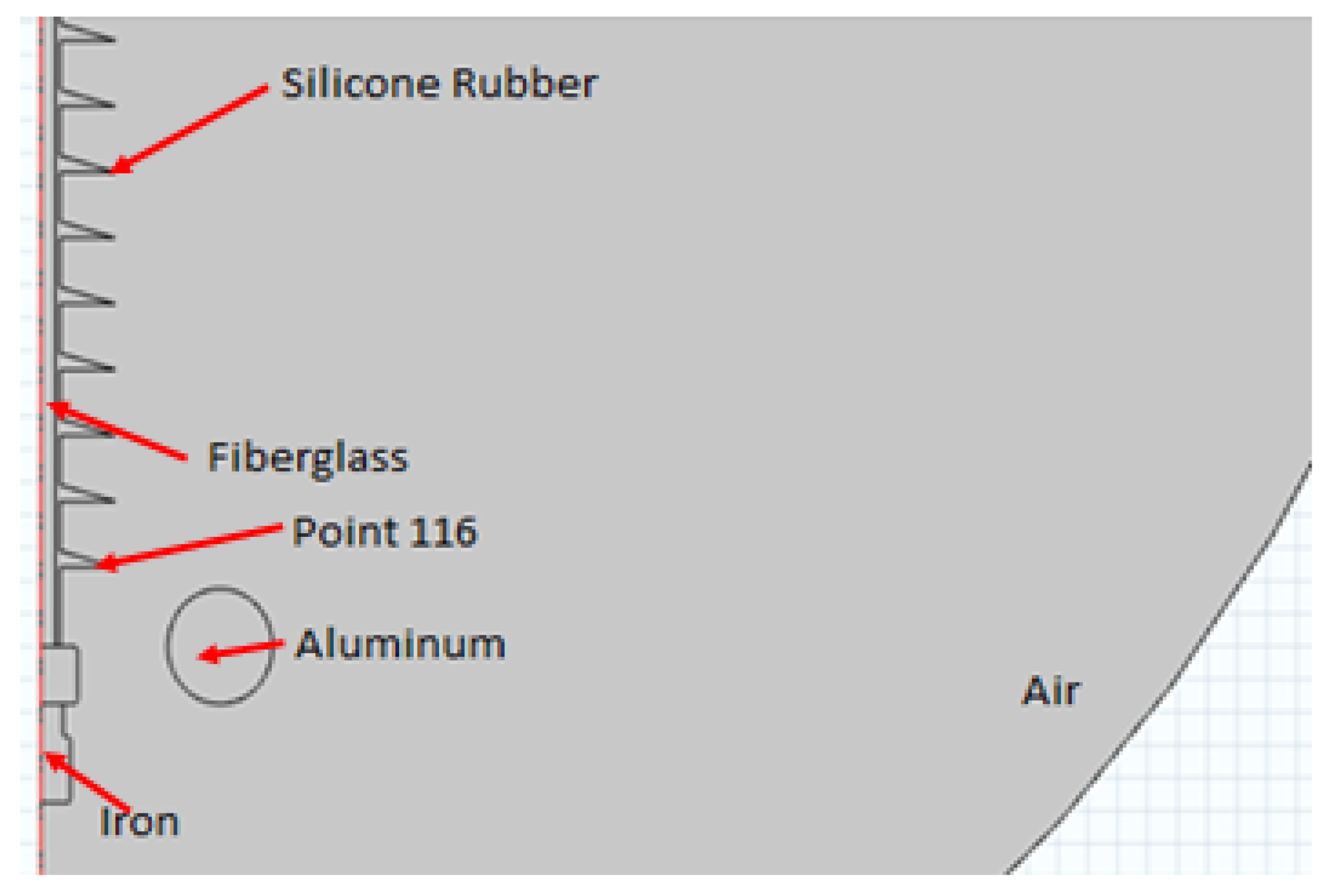
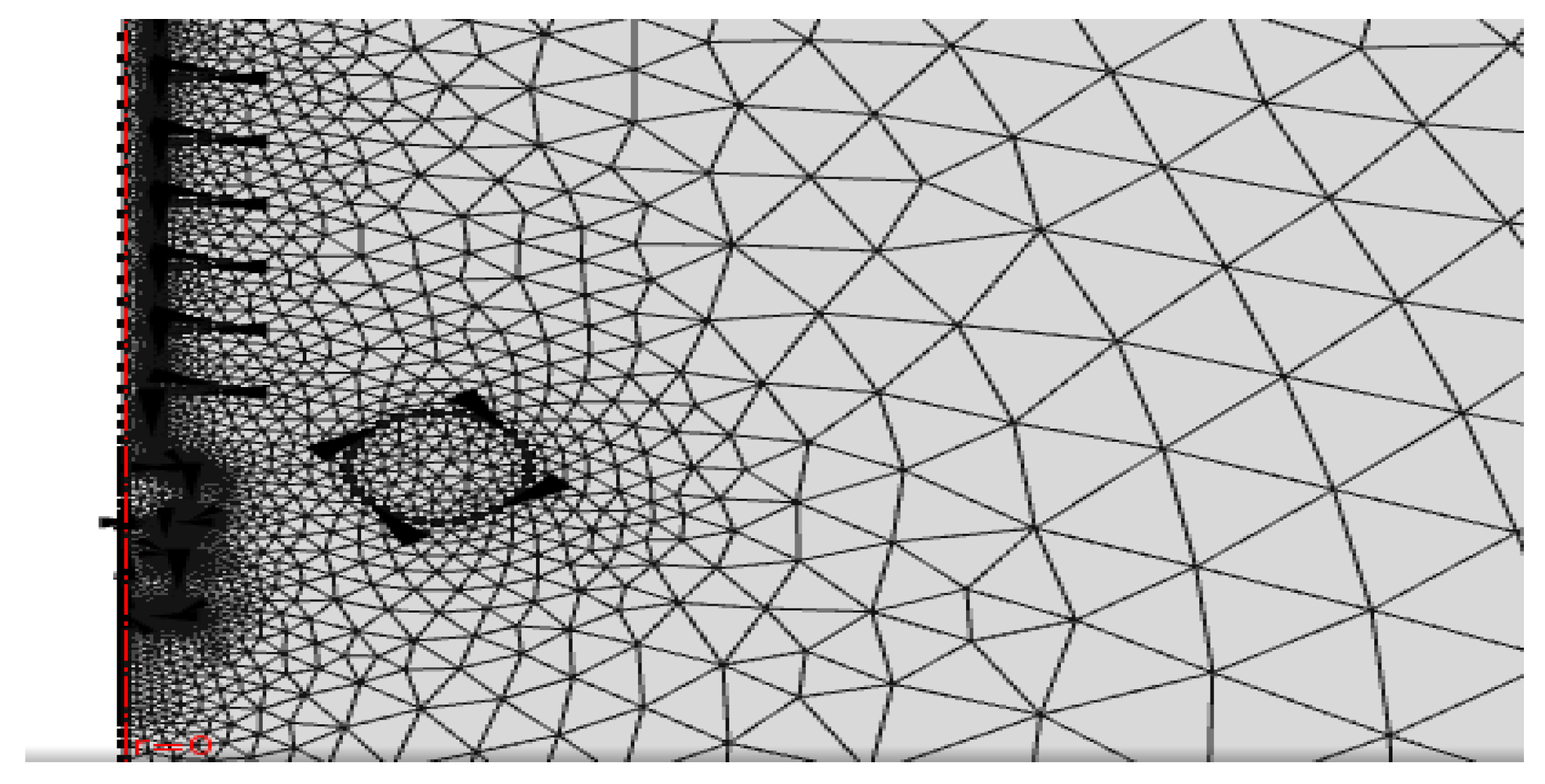
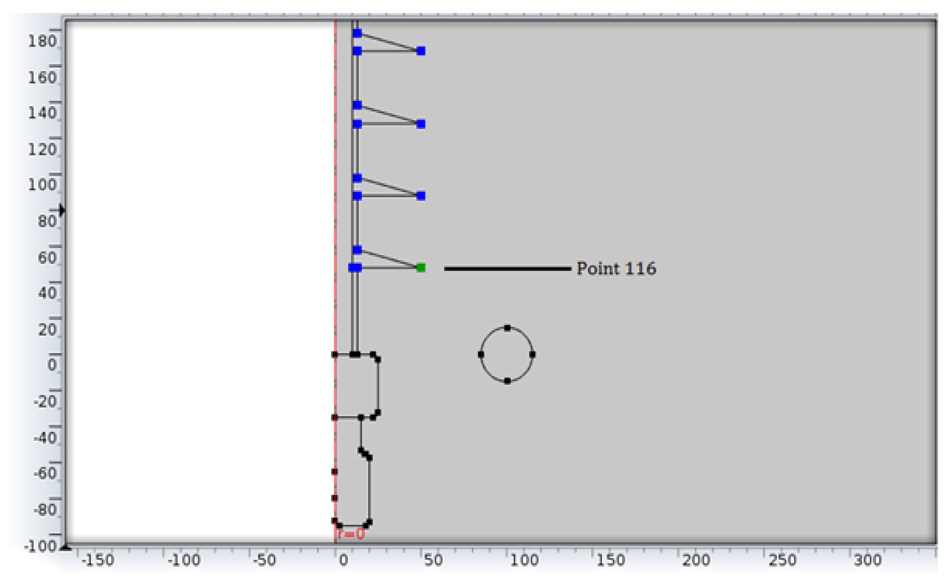
2.1. Model of 132 kV Non-Ceramic Insulator Model and Corona Ring

Figure 1 refers to a two-dimensional (2D) geometry model of a 132 kV non-ceramic insulator and its corona ring. The measurements of the insulator string were developed in the software based on the available datasheet from a selected manufacturer. Both ends of the insulator were made with iron and top iron was connected to the ground end while the bottom end was supplied with a 132 kV applied voltage. The complete model was surrounded with air to evaluate the distribution of the electric field magnitude on the insulator surface. The outer air boundary was set to zero charge to model an infinite air region as a limited region. Table 1 shows the dimensions of the insulator string developed in this work.
Figure 2 shows a corona ring and its dimensions selected in this work, such as the ring diameter (R), diameter of the ring tube (r) and the vertical position of the ring on the insulator (H). These dimensions were set as the variables for the optimisation algorithms in order to achieve the minimum electric field along the insulator string. The size of the corona ring installed with the insulator string has a strong influence on the electric field distributions. This corona ring and its dimensions are applied with 132 kV.
The electrical conductivity σ and relative permittivity εr of each part of the material in the model were allocated as listed in Table 2. Table 3 shows the condition of all the boundaries in the model that were fixed with the relevant interface settings. The boundary conditions for an electric field analysis are available with the AC/DC Module, such as the capability to give the total electric field on a boundary. A 132 kV voltage was applied at the terminal with the presence of harmonic while the bottom of the insulator was grounded with 0 V. The outer part of the insulator was surrounded by a layer of air and all the interiors were set to continuity. The simulation results are sensitive to the properties of the materials in Table 2 as inputs to the simulation. Hence, the optimisation algorithms are useful to determine the most optimal design of the corona ring.
After the material and boundary were set, the model was meshed. By using the elementary shape functions such as the cubic, rectangular, edge and solid elements, the model in the FEA evaluates the solution of all the domains, boundaries, edges and points of insulator string. The shape function in the model can be of a constant, linear or higher order. Different mesh sizes were tried out to make sure the FEM results converged. A finer or coarser mesh is required to obtain an accurate result based on the element sequence in the insulator string model. The size of the cubic elements used for the air was normal and all the domains of the model were using a finer element since the cubic elements had a substantial effect on the simulation time. For the domain of the insulator string, the elements of the cubic were used, and the solid elements for the boundary and edge elements were used for all the edges. Figure 3 shows the elements of meshing in the 2D model.
The equations applied to obtain the electric potential distribution in the model is governed by [18]:
𝛻 · ε 0 ε r   𝛻 V = 0
where εr is the relative permittivity of the material and ε0 is the vacuum permittivity. Between two dielectrics, the boundary condition is:
n ^ · D 1 D 2 = 0
where D1 and D2 are the electric displacement and n is the unit vector normal to the surface.
For the high voltage terminal, where V0 is the applied voltage, the boundary condition is:
V = V0
The boundary condition for the ground is given by [18]:
V = 0

2.2. Objective Function for the Optimisation

There have been many analytical and numerical methods of swarm intelligence optimisation algorithms in recent years [19]. These algorithms attained the optimal status when each individual was working together in a group. Swarm intelligence algorithms become the important spots for an algorithm optimisation and are largely applied in various fields [20,21]. Particle swarm optimisation (PSO), binary particle swarm optimisation (BPSO), Grey Wolf Optimisation (GWO), the gravitational search algorithm (GSA) and imperialist competitive algorithms (ICA) are commonly used algorithms [22]. In this work, GWO and the ICA were chosen because of the imperialistic competition development method in the ICA and the accelerated speed of convergence in GWO compared to other algorithms.
The objective of the optimisation techniques is to find the corona ring optimal dimension on the insulator model. The position of the corona ring on the insulator string H, the diameter of the ring R and the diameter of the ring tube r are the parameters varied in this technique. The objective function is minimisation of the electric field. The equation of the objective function is given by:
Fitness function = Min (Electric field)

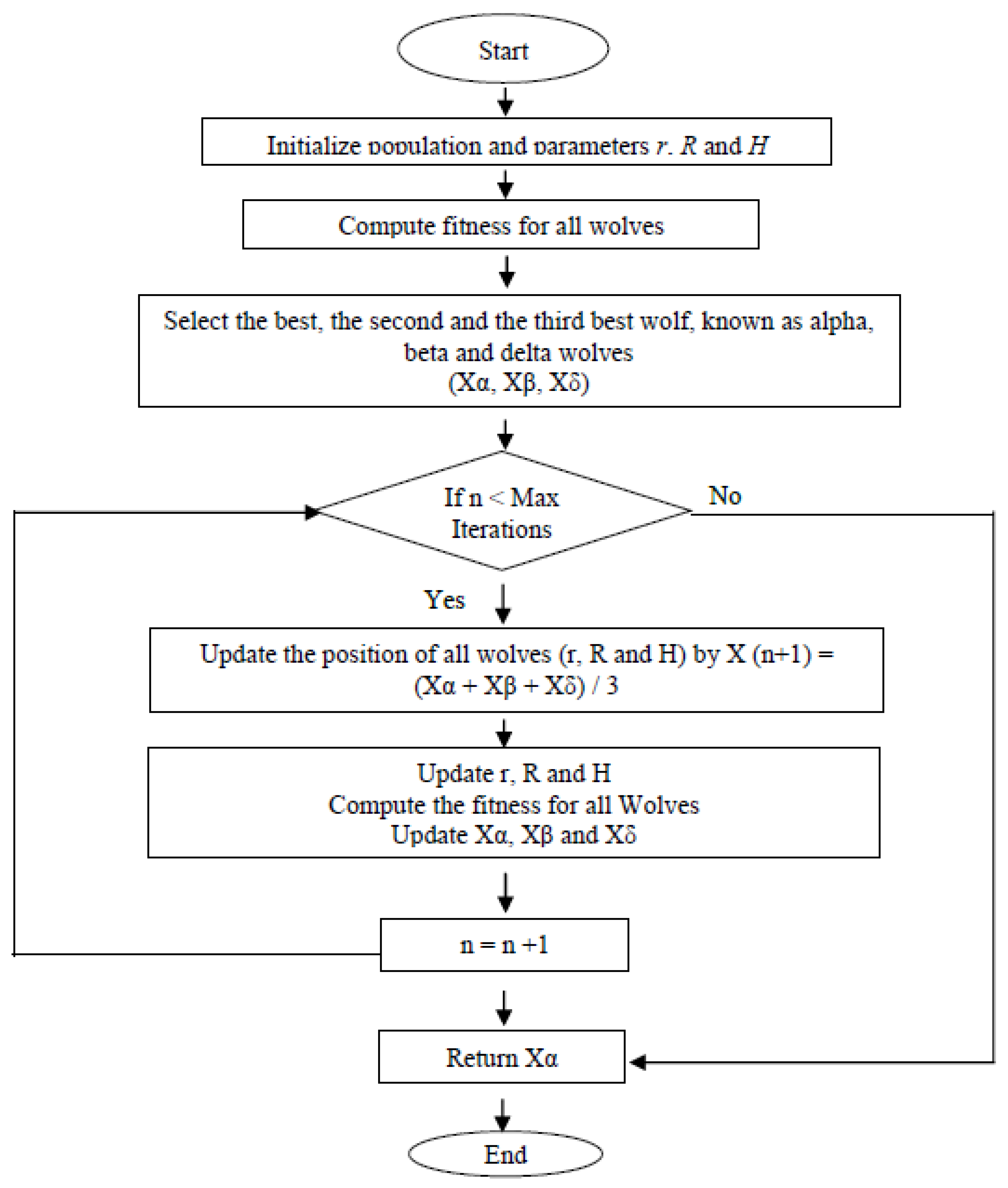
2.3. Grey Wolf Optimisation (GWO)

Grey Wolf Optimisation (GWO) algorithm was proposed by Mirjalili et al. [23,24] in 2014. GWO is a developed computational method in swarm intelligence algorithms which replicates the grey wolves preying behaviour. This algorithm has better results to settle the complicated engineering problems. For the purpose of speeding up the convergence and enhancing the strength of the optimisation, various upgraded GWO algorithms have arisen [20]. The advantages of using GWO are that it improves the global search performance, speeds up the convergence of the algorithms and the global search capability is dynamically compared to the other type of swarm intelligence algorithms [25,26]. The convergence factor in the search space is balancing the capability of the algorithm for both a global search and local search [27,28].
There are four groups in grey wolf: the leader wolf α, the captain wolf δ, the deputy leader wolf β and the individual wolf ω [20]. The α, β and δ determine the pursue position and the other wolves will update their position randomly around the pursue. This step is continued until the required condition is met [29]. The steps of the GWO algorithm are illustrated in Figure 4.

2.4. Imperialist Competitive Algorithm (ICA)

The ICA is known as a mathematical model and computer simulation of human social development. It is also socio-political metaheuristics motivated by a historical colonisation procedure and competition between the imperialist to detain more colonies. The ICA is a new algorithm that was proposed by Esmaeil Atashpaz Gargari and Caro Lucas in 2007 [15]. The purpose of using the ICA is because it has a considerable development compared to other nature-inspired algorithms in obtaining the optimum solution with a smaller computational time with a similar population and iteration. Although the ICA was introduced recently, it has been successful in many applications, for example, in chemical possesses, intelligent recommender systems, the optimal controller for an industrial use and adaptive antenna arrays [30,31]. Imperialistic competition approaches to a condition where only one empire exists and its colonies are in the same position. Most of the researchers concluded that the ICA is effective in the search space exploration and achieves more promising results. This makes the ICA the best optimisation technique for long-term reconfiguration problems. Figure 5 indicates the flowchart of the ICA applied in this research work.
Optimisation algorithms that include GWO and the ICA are applied to achieve the lowest electric field distribution along the insulator string by varying the dimensions of the corona ring. Both methods are not adopted for optimising the parameters in the developed model because of the size of the corona ring.

3. Results and Discussion

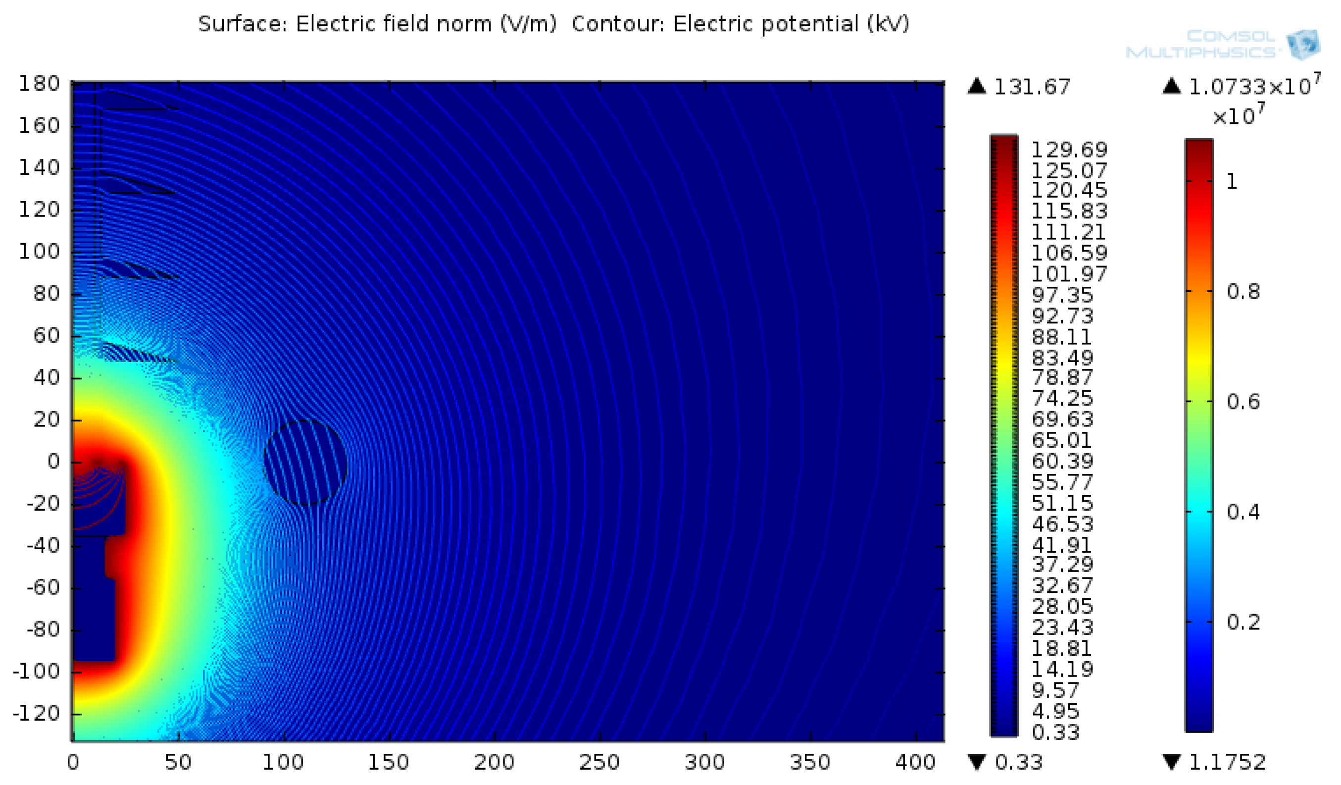
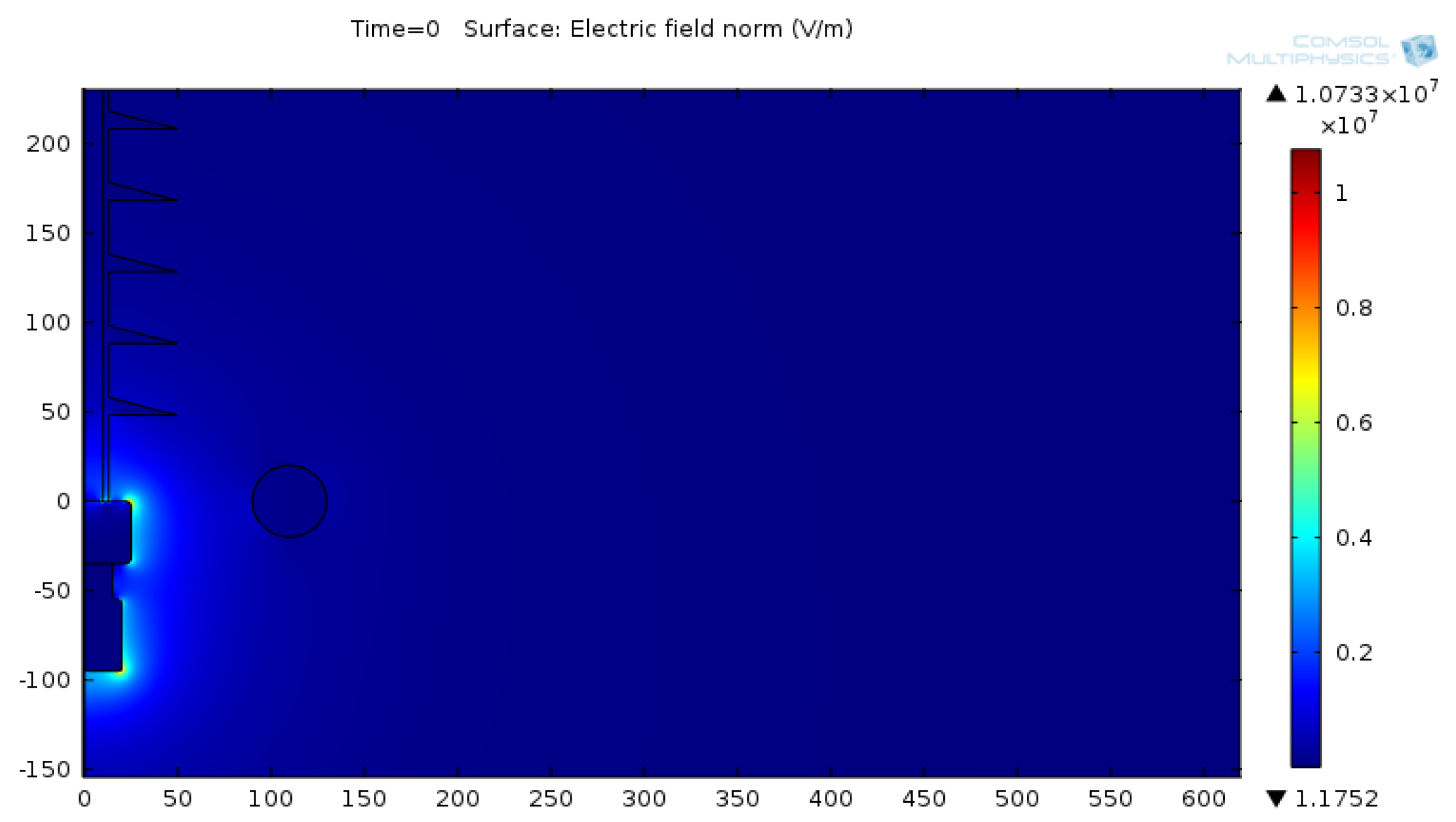
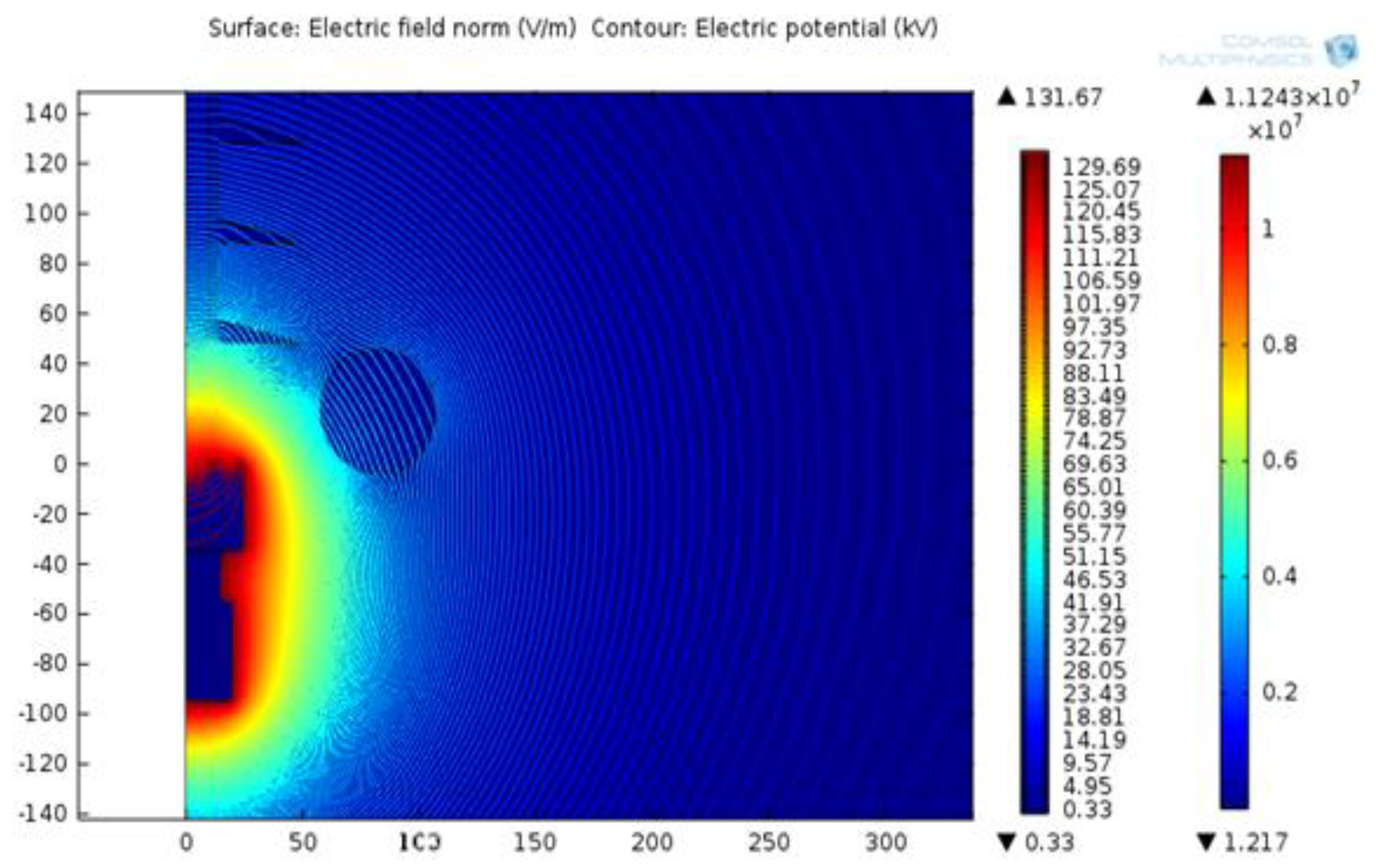
3.1. Distributions of Electric Field and Electric Potential on 132 kV Insulator String

The simulation results for the 132 kV of the insulator string with the corona ring model that has been designed are presented in this section. The simulation results of electric potential distribution and electric field distribution were optimised with and without a corona ring using different dimensions and were compared with the results using non-linear optimisation methods. The distributions of the electric field and electric potential around the energised end along the insulator are examined using COMSOL Multiphysics. The comparisons are done for the two-dimensional (2D) simulation models and the critical points affecting the simulation accuracy are examined. The maximum recommended electric field by the IEEE task force is 4.5 kV/cm. The attachment of the corona ring to the insulator aids the system with a lower corona effect, hence prolonging the insulator life, minimising the maximum electric field along the surface of the insulator and avoiding an excessive level of radio interference. Figure 6 and Figure 7 show the electric potential and electric field distribution obtained from the FEA model geometry. The results in these figures agree with the simulation results reported in [1,8,11]. Thus, the simulation model and its results can be considered acceptable.

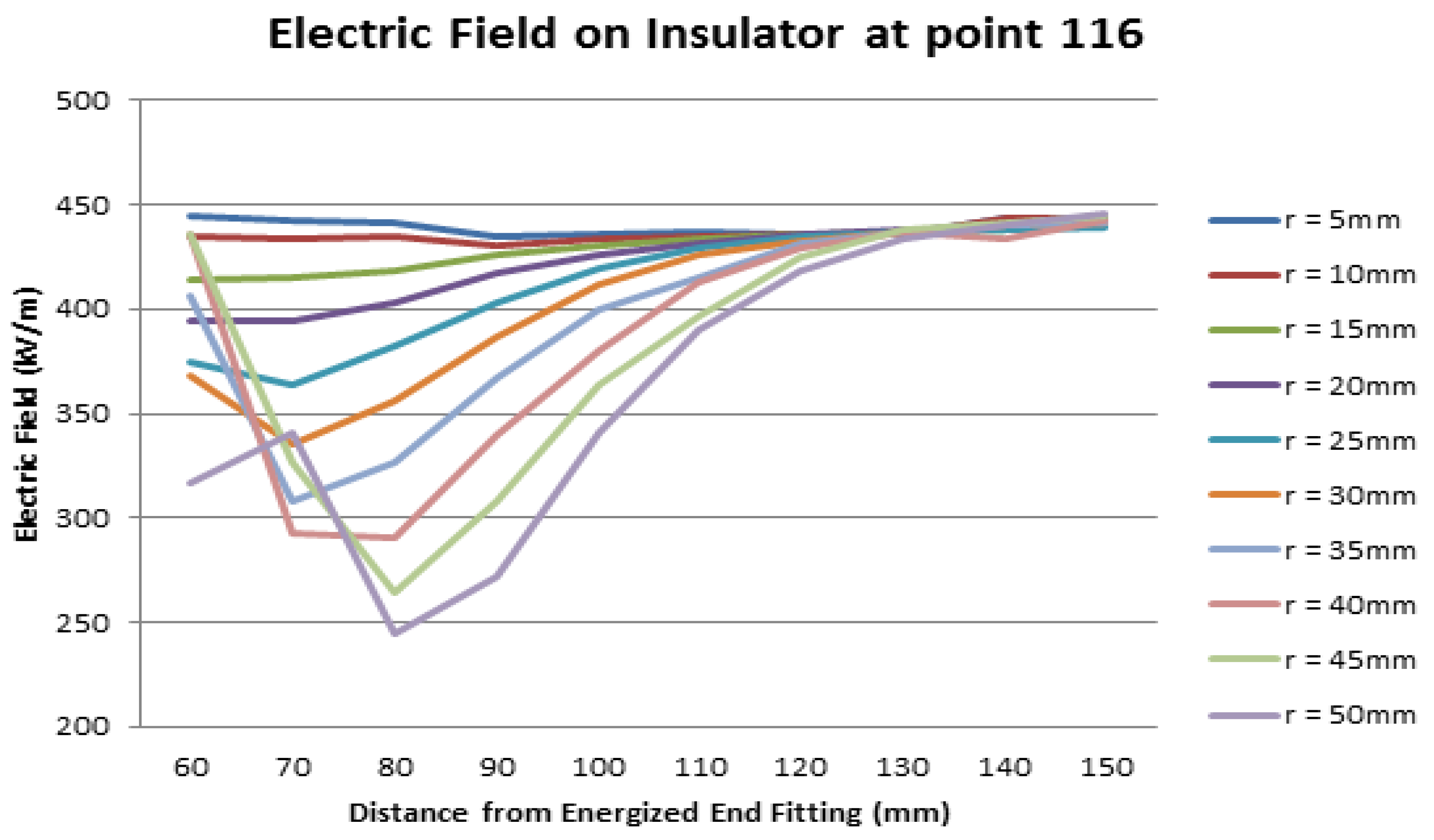
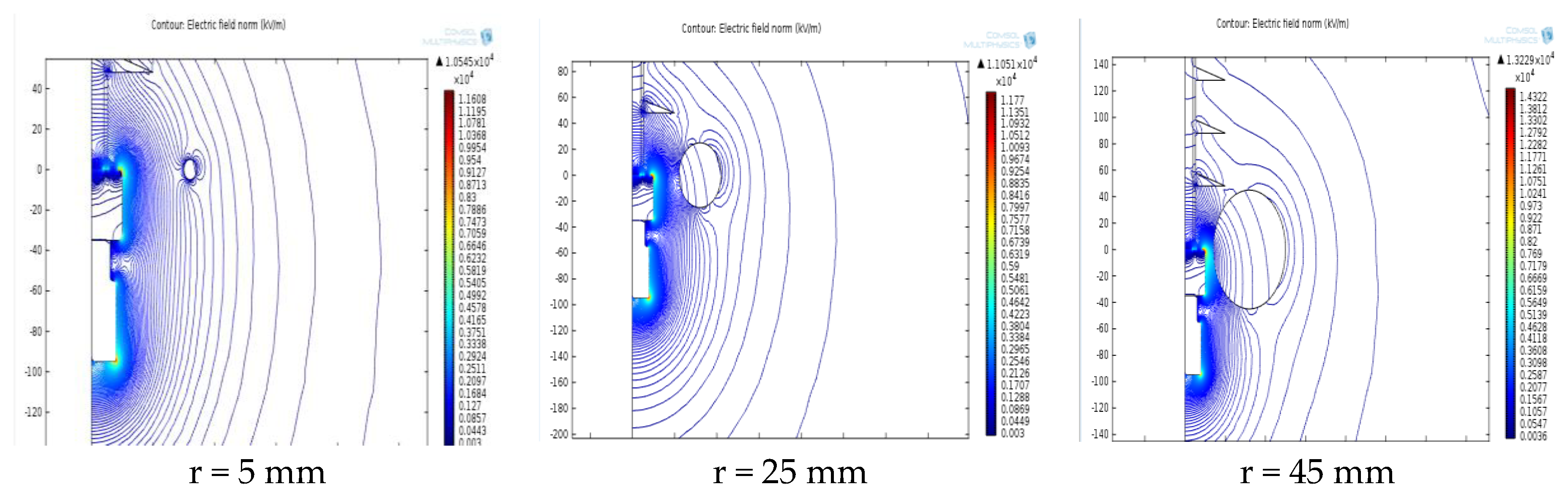
3.2. Simulation Results Using Various Parameter Values of Corona Ring in 132 kV Insulator String

To analyse the effect of the variable parameters on the design at point 116 (referring to Figure 1), the electric field was computed for the practical values of R, r and H separately, while making the other parameters constant. In this section, the simulation processes were done for all the selected parameters. The results of the electric field [kV/cm] were collected. The variation in the ring diameter, R, is between the ranges of 60 mm and 150 mm, whereas the variation in the diameter of the ring tube, r, is between 5 and 50 mm. The vertical position of the ring, H, was fixed at 0 for all the simulation steps. Figure 8 shows the selected point 116, along the insulator string surface, where this is the point that has a high electric field without a corona ring.
Table 4 shows the data collected from the simulation for a minimum electric field with a corona ring at point 116. Although the optimisation of the insulator design was focused on point 116, a few other points were also taken into account in this simulation for comparison. The cells highlighted in red in Table 4 are the electric field on the insulator surface below 4.5 kV/cm, where 4.5 kV/cm is the maximum electric field recommended by the IEEE task force. From this simulation result, the lowest minimum value for the electric field is 3.827 kV/cm with the optimal dimensions; R is 80 mm, r is 25 mm and H is 0. However, some values from Table 4 are not considered even though the values are below 3.827 kV/cm, such as 3.658 kV/cm (R = 90 mm and r = 35 mm) and 3.619 kV/cm (R = 100 mm and r = 45 mm). This is because the corona ring is overlapping the insulator, as in Figure 9, which should be considered. Apart from that, “N/A” in Table 4 also showed that those values cannot be evaluated due to the corona ring overlapping with the insulator string.
The results indicate that the highest electric field is not all the time at point 116, but it differences are according to the dimensions and position of the corona ring. The nearer the corona ring is to the insulator, lower the fields in the area near to the end-fitting. However, the fields along the sheath far from the end-fitting are higher for smaller diameters. There is a small impact on the electric field magnitude at the energised end when increasing or decreasing the ring diameter compared to the ring position. From Figure 10, it can be seen that the electric field at point 116 is decreased when the diameter of the ring tube, r, is increased. A contour figure is shown in Figure 11, which shows the variation in r and the changes in the electric field.

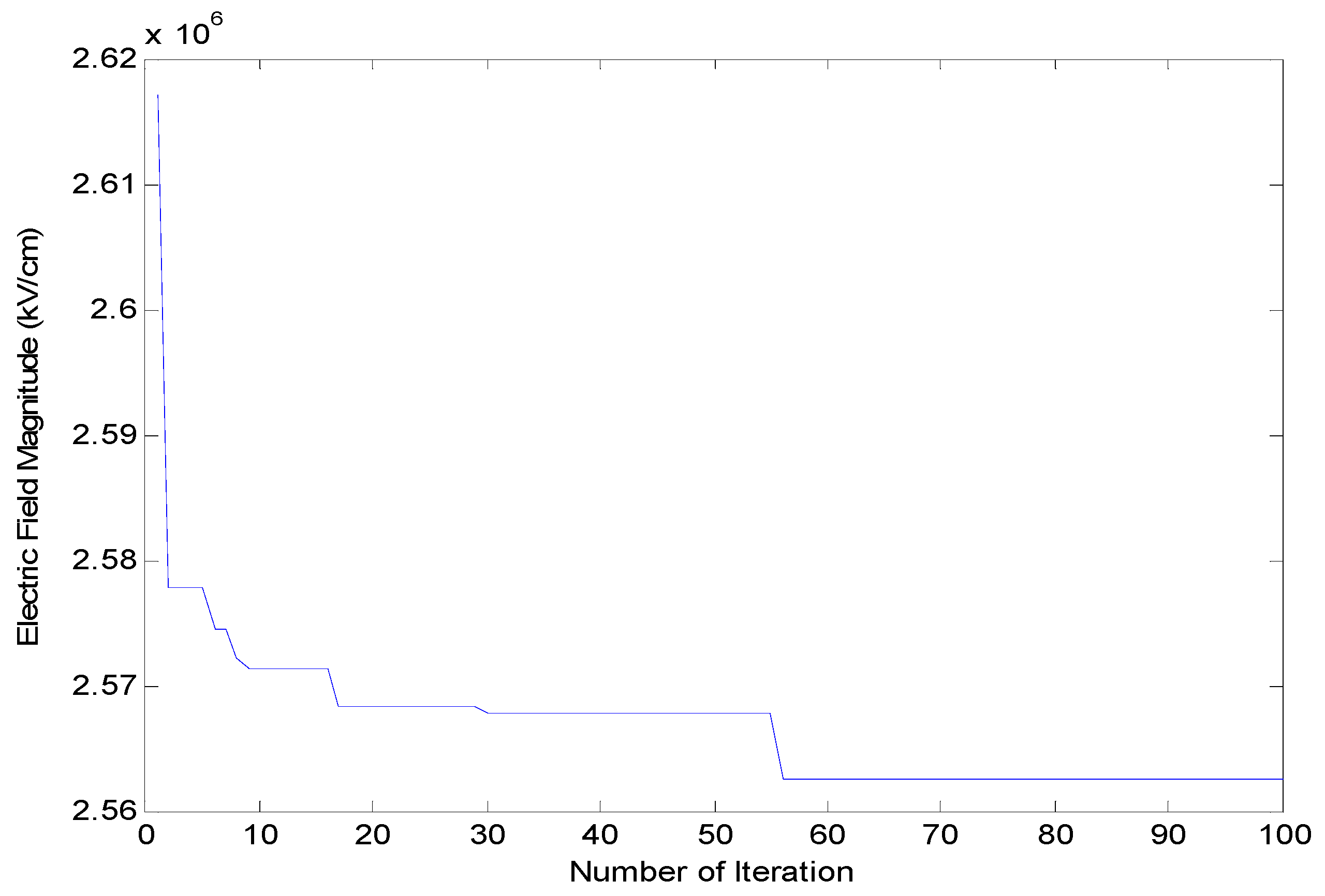
3.3. Optimisation Results Using ICA and GWO for 132 kV Insulator String

Two different non-linear optimisation techniques, the Imperialist Competitive Algorithm (ICA) and Grey Wolf Optimisation (GWO), were used to obtain the lowest electric field magnitude for a 132 kV insulator string. For this model, a GSA technique is not applied because its optimisation results are not suitable for a higher applied voltage. The results achieved from the model of the insulator string with the corona ring were combined with the MATLAB script to achieve the objective function. The results from the ICA and GWO are compared and explained. There are few dimensions used on the corona ring and insulator string. The main ring dimensions in the corona ring model are the ring diameter R, the vertical position of the ring along the insulator H and the diameter of the ring tube r. These parameters are optimised by the ICA and GWO in order to achieve the lowest electric field along the insulator string.
Three cases were evaluated in this optimisation work. For case 1, the dimension which needs to be optimised is the diameter of the ring tube, r. For case 2, the dimensions for both the diameter of the ring tube, r, and the ring diameter, R, of the corona ring are optimised. For case 3, it is the diameter of the ring tube, r, the ring diameter, R, and the height of the ring, H. Table 5 shows summarised descriptions of all the case studies while Figure 12 shows the materials and domains that were optimised.
The lower and upper limit of every variable are kept based on the limits relative to the ring dimension, as shown in Table 6. The number of the iterations used in the ICA and GWO is 100. Figure 13 and Figure 14 show the results after 100 iterations for both optimisation methods. GWO achieved the solution at iteration 56, while the ICA achieved the solution at iteration 72. Hence, GWO attains the best solutions quicker than the ICA for the optimal design of a corona ring on the insulator string model.
In order to explain the mechanism of each of the optimisation methods, Figure 13 and Figure 14 are referred to. The electric field magnitude is converging towards the minimum value against the iteration. For GWO, the process of searching begins with generating a random population of grey wolves, or the solutions of the candidates, which in this case are the diameter of the ring tube, ring diameter and vertical position of the ring along the insulator. The solution of every population, which is the electric field magnitude, is calculated. At every iteration, the alpha, beta and delta wolves are estimating the possible position of the prey. Every candidate updates its distance from their prey. The exploration and exploitation of the best solution are emphasised. The best solution is achieved when the distance between the wolves and their prey is converging.
For the ICA, the process of searching begins with generating a random population of initial empires, which in this case are the diameter of the ring tube, the ring diameter and the vertical position of the ring along the insulator. The colonies are assimilated. At every iteration, any colony in an empire that has a lower cost or a lower electric field magnitude than the imperialist will exchange the position of the imperialist with the colony. The weakest colony from the weakest empire is picked and it is given to the empire that has the highest probability to possess it. Any empire that has no colony will be eliminated. At the end, the best result, or the lowest electric field magnitude, is obtained when only one empire is left.
Table 7 shows the results for all three case studies. For case 1, which is the varying diameter of the ring tube, it shows that the electric fields achieved by the ICA and GWO are similar. In Case 1, the diameter of the ring tube value of both techniques is the same. Case 2 shows the result of the varying ring diameter of the corona ring. The electric field attained using GWO is lower than the ICA while for Case 3, it shows that the ring vertical position along the insulator in the ICA is higher than GWO.
A comparison is made between the ICA and GWO, which have been used to obtain the optimum dimensions and the lowest electric field on the insulator string. From the result, the GWO optimisation technique gives better results compared to the ICA optimisation technique. All three parameters, the r, R and H, have lower values in GWO compared to the ICA method. The minimum electric field obtained from case 3 is compared to cases 1 and 2. From the comparison using the GWO method, the electric field from the optimised results is about 10.3% lower than without the optimisation.
Finally, the optimum dimensions of the corona ring, which yield the lowest electric field, were identified, which are R = 82.181 mm, r = 24.897 mm and H = 20.978 mm. Figure 15 shows the simulation results with the optimum dimensions, where the minimum electric field simulated is 3.724 kV/cm.

4. Conclusions

In this work, the effect of different corona ring dimensions along the insulator string and distributions of the electric field has been successfully analysed using a simulation model. A two-dimensional 132 kV composite insulator geometry model has been successfully designed with a corona ring and without a corona ring in finite element analysis (FEA) software to obtain the distribution of the electric field magnitude. From these results, it was found that the implementation of a corona ring at the insulator string can reduce the electric field significantly at the energised end of the insulation string. This is due to more of the electric field being re-distributed towards the unenergised end of the insulator string with the presence of the corona ring. The distribution of the electric field on the insulator string depends on the vertical position of the ring along the insulator string, the corona ring diameter and the ring tube diameter. Thus, the proposed FEA model for corona ring modelling along the insulator string in this work can be considered reasonable.
Optimisation methods were successfully executed in this research work to achieve the optimum design of the corona ring along a 132 kV composite insulator string. Applying optimisation methods, a minimum electric field magnitude at the energised end of the insulator is achieved compared to without applying the optimisation method by between 3.724% and 3.827%. The comparison between the two optimisation methods shows that Grey Wolf Optimisation (GWO) yields the minimum electric field magnitude along a 132 kV insulator string and converges faster than the Imperialist Competitive Algorithm (ICA). This is due to GWO achieving the solutions faster than the ICA. Hence, GWO is recommended over the ICA for the design optimisation of a corona ring on insulator strings for a different level of voltage.
The electric field distribution results, simulation results and optimisation results of the insulator string model can be obtained and a comparison between the simulation and measurement results can be done in the future. The best optimisation design of the corona ring is focusing on reducing the distribution of the electric field along the insulator. However, the simulation model also can be improved by including the effect of the corona ring’s dimensions due to a different environment and a natural problem. By adding the layer of pollution along the insulator and installing the optimal dimension of the corona ring, the minimum electric field distribution can be obtained. Additionally, the simulation model can be improved by increasing the number of parameters to be optimised, such as the permittivity of the insulator.
In this work, it has been demonstrated that the heuristic algorithm is suitable to obtain the optimal dimensions of a corona ring for an insulator string model. However, in the future, the application of deterministic algorithms, apart from heuristic algorithms, for different parameters of the corona ring will be considered.

Author Contributions

Conceptualization, K.A., Y.C.C., M.S.A. and M.Z.H.M.; formal analysis, K.A. and H.A.I.; funding acquisition, K.A.; investigation, K.A.; methodology, K.A. and M.S.A.; resources, H.A.I.; supervision, H.A.I. and Y.C.C.; validation, H.A.I. and M.Z.H.M., writing—original draft, K.A.; writing—review and editing, H.A.I., Y.C.C., M.S.A. and M.Z.H.M. All authors have read and agreed to the published version of the manuscript.

Funding

This research was funded by the Ministry of Higher Education Malaysia through High Impact Research Grant H-16001-D00048 and Universiti Malaya through SATU Joint Research Grant ST071-2021 and Impact-Oriented Interdisciplinary Research Grant Program IIRG001B-2020IISS. The APC was funded by Universiti Malaysia Sabah (UMS).

Data Availability Statement

Not applicable.

Acknowledgments

The authors thank the Ministry of Higher Education Malaysia, Universiti Malaya and the Faculty of Science and Natural Resources, Universiti Malaysia Sabah (UMS) for supporting this work through research fund.

Conflicts of Interest

The authors declare no conflict of interest.

References

  1. Murawwi, E.A.; El-Hag, A. Corona ring design for a 400 kV non-ceramic insulator. In Proceedings of the 2nd International Conference on Electric Power and Energy Conversion Systems (EPECS), Sharjah, United Arab Emirates, 15–17 November 2011; pp. 1–4. [Google Scholar]
  2. Barros, R.M.R.; Costa, E.G.D.; Ferreira, T.V.; Araujo, J.F.; Andrade, F.L.M. A new approach for optimal design of corona ring. In Proceedings of the IEEE International Power Modulator and High Voltage Conference (IPMHVC), San Francisco, CA, USA, 6–9 July 2016; pp. 684–687. [Google Scholar]
  3. Arumugam, S.; Haba, Y.; Koerner, G.; Uhrlandt, D.; Paschen, M. Understanding partial discharges in low-power relay and silicone cable modified to suit high-voltage requirement of deep sea electrical system. Int. Trans. Electr. Energy Syst. 2018, 28, e2542. [Google Scholar] [CrossRef]
  4. Riba, J.R.; Capelli, F. Analysis of Capacitance to Ground Formulas for Different High-Voltage Electrodes. Energies 2018, 11, 1090. [Google Scholar] [CrossRef] [Green Version]
  5. Hu, H.; Zhang, X.; Liu, Y.; Guo, L. Optimization of the Electric Field Distribution at the End of the Stator in a Large Generator. Energies 2018, 11, 2510. [Google Scholar] [CrossRef] [Green Version]
  6. Mohammad, S.; Hoseini, H.F.; Mahdi, M.A.; Tavakoli, M. Electric Field Distributions around Silicon Rubber Insulators in Polluted and Cleaned Area. Int. J. Sci. Eng. Investig. 2013, 2, 137–140. [Google Scholar]
  7. Zhang, D.; Liu, J.; Fengbo, T.; Huang, X.; Yang, C.; Zhang, Z. Research on the Non-Contact Pollution Monitoring Method of Composite Insulator Based on Space Electric Field. Energies 2021, 14, 2116. [Google Scholar] [CrossRef]
  8. Phillips, A.J.; Kuffel, J.; Baker, A.; Burnham, J.; Carreira, A.; Cherney, E.; Chisholm, W.; Farzaneh, M.; Gemignani, R.; Gillespie, A.; et al. Electric Fields on AC Composite Transmission Line Insulators. IEEE Trans. Power Deliv. 2008, 23, 823–830. [Google Scholar] [CrossRef]
  9. Yang, W.; Zhu, T.; Tian, Y.; Zhu, S.; Yang, X. Computation and Analysis of Electric Field Distribution Under Lightning Impulse Voltage for 1000-kV Gas-Insulated-Switchgear Spacer. J. Electr. Eng. Technol. 2020, 15, 1745–1758. [Google Scholar] [CrossRef]
  10. Niedospial, E. Design and application of corona and grading rings for composite insulators. In Proceedings of the PES T&D, Orlando, FL, USA, 7–10 May 2012; pp. 1–3. [Google Scholar]
  11. Terrab, H.; Kara, A. Parameters design optimization of 230 kV corona ring based on electric field analysis and response surface methodology. Electr. Power Syst. Res. 2017, 163, 782–788. [Google Scholar] [CrossRef]
  12. Can, Y.; Aydogan, O.; Suat, I. Electric field distributions around composite insulators under AC and impulse voltages. In Proceedings of the Modern Electric Power Systems, Wroclaw, Poland, 20–22 September 2010; pp. 1–6. [Google Scholar]
  13. Sima, W.; Wu, K.; Yang, Q.; Sun, C. Corona Ring Design of ±800kV DC Composite Insulator Based on Computer Analysis. In Proceedings of the IEEE Conference on Electrical Insulation and Dielectric Phenomena, Denver, CO, USA, 15–18 October 2006; pp. 457–460. [Google Scholar]
  14. Lalitha, M.; Kumar, K.V.; Samala, V. Design and simulation of voltage and electric field distribution on disc insulators using finite element method in Opera software. In Proceedings of the International Conference on Smart Electric Grid (ISEG), Guntur, India, 19–20 September 2014; pp. 1–6. [Google Scholar]
  15. Rout, U.K.; Sahu, R.K.; Panda, S. Gravitational Search Algorithm based Automatic Generation Control for interconnected power system. In Proceedings of the International Conference on Circuits, Power and Computing Technologies (ICCPCT), Nagercoil, India, 20–21 March 2013; pp. 558–563. [Google Scholar]
  16. Gierczak, M.; Markowski, P.M.; Dziedzic, A. The Modeling of Magnetic Fields in Electromagnetic Microgenerators Using the Finite Element Method. Energies 2022, 15, 1014. [Google Scholar] [CrossRef]
  17. Stefanini, D.; Seifert, J.M.; Clemens, M.; Weida, D. Three dimensional FEM electrical field calculations for EHV composite insulator strings. In Proceedings of the IEEE International Power Modulator and High Voltage Conference, Atlanta, GA, USA, 23–27 May 2010. [Google Scholar]
  18. Bakar, A.; Abidin, A.; Illias, H.; Mokhlis, H.; Abd Halim, S.; Hassan, N.; Tan, C.K. Determination of the striking distance of a lightning rod using finite element analysis. Turk. J. Electr. Eng. Comput. Sci. 2016, 24, 4083–4097. [Google Scholar] [CrossRef]
  19. Marghny, M.; Zanaty, E.A.; Dukhan, W.H.; Reyad, O. A hybrid multi-objective optimization algorithm for software requirement problem. Alex. Eng. J. 2022, 61, 6991–7005. [Google Scholar] [CrossRef]
  20. Yan, C.; Chen, J.; Ma, Y. Grey Wolf Optimization Algorithm with Improved Convergence Factor and Position Update Strategy. In Proceedings of the 11th International Conference on Intelligent Human-Machine Systems and Cybernetics, Hangzhou, China, 24–25 August 2019; pp. 41–44. [Google Scholar]
  21. Sabo, A.; Abdul, W.N.I.; Othman, M.L.; Mohd, J.M.Z.A.; Beiranvand, H. Optimal design of power system stabilizer for multimachine power system using farmland fertility algorithm. Int. Trans. Electr. Energy Syst. 2020, 30, e12657. [Google Scholar] [CrossRef]
  22. Ibrahim, K.S.M.H.; Huang, Y.F.; Ahmed, A.N.; Koo, C.H.; El-Shafie, A. A review of the hybrid artificial intelligence and optimization modelling of hydrological streamflow forecasting. Alex. Eng. J. 2022, 61, 279–303. [Google Scholar] [CrossRef]
  23. Mirjalili, S.; Mirjalili, S.; Lewis, A. Grey Wolf Optimizer. Adv. Eng. Softw. 2014, 69, 46–61. [Google Scholar] [CrossRef] [Green Version]
  24. Djerioui, A.; Houari, A.; Machmoum, M.; Ghanes, M. Grey Wolf Optimizer-Based Predictive Torque Control for Electric Buses Applications. Energies 2020, 13, 5013. [Google Scholar] [CrossRef]
  25. Yu, H.; Yu, Y.; Liu, Y.; Wang, Y.; Gao, S. Chaotic grey wolf optimization. In Proceedings of the International Conference on Progress in Informatics and Computing, Shanghai, China, 23–25 December 2016; pp. 103–113. [Google Scholar]
  26. Du, M.; Zhao, Y.; Liu, C.; Zhu, Z. Lifecycle cost forecast of 110 kV power transformers based on support vector regression and gray wolf optimization. Alex. Eng. J. 2021, 60, 5393–5399. [Google Scholar] [CrossRef]
  27. Han, Y.; Tong, X. Multi-Step Short-Term Wind Power Prediction Based on Three-level Decomposition and Improved Grey Wolf Optimization. IEEE Access 2020, 8, 67124–67136. [Google Scholar] [CrossRef]
  28. Ansari, M.M.; Guo, C.; Shaikh, M.S.; Chopra, N.; Haq, I.; Shen, L. Planning for Distribution System with Grey Wolf Optimization Method. J. Electr. Eng. Technol. 2020, 15, 1485–1499. [Google Scholar] [CrossRef]
  29. Naserbegi, A.; Aghaie, M.; Zolfaghari, A. Implementation of Grey Wolf Optimization (GWO) algorithm to multi-objective loading pattern optimization of a PWR reactor. Ann. Nucl. Energy 2020, 148, 107703. [Google Scholar] [CrossRef]
  30. Eid, A. Allocation of distributed generations in radial distribution systems using adaptive PSO and modified GSA multi-objective optimizations. Alex. Eng. J. 2020, 59, 4771–4786. [Google Scholar] [CrossRef]
  31. Bashiri, M.; Bagheri, M. Using Imperialist competitive algorithm optimization in multi-response nonlinear programming. Int. J. Ind. Eng. Prod. Res. 2012, 24, 229–235. [Google Scholar]
Figure 1. 2D geometry model of non-ceramic insulator and corona ring.
Energies 16 00778 g001
Figure 2. Dimensions of corona ring.
Energies 16 00778 g002
Figure 3. Meshing elements in 2D model.
Energies 16 00778 g003
Figure 4. Flowchart of GWO.
Energies 16 00778 g004
Figure 5. Flowchart of ICA.
Energies 16 00778 g005
Figure 6. Electric potential distribution of an insulator after the simulation.
Energies 16 00778 g006
Figure 7. Electric field distribution of an insulator after the simulation.
Energies 16 00778 g007
Figure 8. Selected point along the insulator.
Energies 16 00778 g008
Figure 9. Overlapping corona ring along insulator string.
Energies 16 00778 g009
Figure 10. Electric field at point 116 for the variation in r and R.
Energies 16 00778 g010
Figure 11. Electric field distribution with variation in diameter of ring tube, r.
Energies 16 00778 g011
Figure 12. Optimised parameters of insulator and corona ring.
Energies 16 00778 g012
Figure 13. Simulation results for GWO after 100 iterations.
Energies 16 00778 g013
Figure 14. Simulation results for ICA after 100 iterations.
Energies 16 00778 g014
Figure 15. Optimal dimensions and minimum electric field.
Energies 16 00778 g015
Table 1. Dimensions of insulator string for 132 kV system voltage.
Typical System VoltageNo. of ShedsLength (mm)Cantilever Strength (kN)Creepage Distance (mm)
132 kV4016506.83914
Table 2. Material properties for each part in the model.
MaterialsRelative Permittivity, εrElectrical Conductivity, σ (S/m)Density, ρ
(kg/m3)
Heat Capacity at a Constant Pressure, Cp (J/kgK)Thermal Conductivity, k
(W/mK)
Aluminium13.774 × 1072700900160
Silicone rubber4.21 × 10−14220319251.38
Fiberglass4.21 × 10−14803900.47
Iron11.12 × 107787044076.2
Air1014500.024
Table 3. Boundary of the electric field.
BoundaryBoundary Setting
TerminalApplied voltage 132 kV
AirElectric insulation
Ground0 V
All interior boundaryContinuity
Table 4. Results of electric field distribution on 132 kV insulator string with the variation in R: H = 0 and r from 5 mm to 50 mm.
Ring Diameter, R (mm)60708090100110120130140150
Points (116) Electric field (kV/cm)4.3144.3254.3334.3384.3484.3544.3564.3564.3554.359r = 5 mm
4.2994.2194.2654.3034.3314.3464.3554.3564.3564.362r = 10 mm
13.9674.0864.1624.2524.2894.3274.3444.3634.3644.365r = 15 mm
17.75711.7004.0104.1614.2484.3134.3414.3614.3664.373r = 20 mm
24.60414.2963.8274.0214.1564.2834.3314.3544.3784.379r = 25 mm
37.63618.45111.9233.8664.0774.2314.3194.3614.3874.393r = 30 mm
67.28525.48114.7393.6583.9684.1254.3054.3594.3874.405r = 35 mm
N/A39.14118.65012.1103.8024.1044.2774.3464.3994.409r = 40 mm
N/A70.14325.97014.8663.6193.9544.2084.3244.3924.431r = 45 mm
N/AN/A41.38618.94412.1323.8084.0994.2604.3564.399r = 50 mm
Table 5. Description of the case studies using optimisation techniques.
CasesParameters: Description
Case 1Diameter of ring tube, r
Case 2Diameter of ring tube, r
Ring diameter, R
Case 3Diameter of ring tube, r
Vertical position of the ring along the insulator, H
Ring diameter, R
Table 6. Upper and lower limits of each parameter for the algorithm.
ParametersLower LimitUpper Limit
Ring diameterRmin = 60 mmRmax = 150 mm
Diameter of ring tube rmin = 5 mmrmax = 50 mm
Vertical position of the ring along the insulatorHmin = 0 mmHmax = 100 mm
Table 7. Optimised parameters using ICA and GWO.
CaseOptimised ParametersParameter Measurements (mm)Electric Fields at Point 116 (kV/cm)Without Optimisations
ICAGWOICAGWO
Case 1r24.11424.13.8713.8593.827
Case 2r23.99924.223.923.8993.827
R82.14581.37
Case 3r25.11224.93.7773.7243.827
R83.14782.18
H21.71820.98
Disclaimer/Publisher’s Note: The statements, opinions and data contained in all publications are solely those of the individual author(s) and contributor(s) and not of MDPI and/or the editor(s). MDPI and/or the editor(s) disclaim responsibility for any injury to people or property resulting from any ideas, methods, instructions or products referred to in the content.

