Review

Power Hardware-in-the-Loop (PHIL): A Review to Advance Smart Inverter-Based Grid-Edge Solutions

1
Department of Electrical and Computer Engineering, Baylor University, Waco, TX 76798, USA
2
Department of Mechanical Engineering, Baylor University, Waco, TX 76798, USA
*
Author to whom correspondence should be addressed.
Energies 2023, 16(2), 916; https://doi.org/10.3390/en16020916
Submission received: 3 December 2022 / Revised: 2 January 2023 / Accepted: 10 January 2023 / Published: 13 January 2023
(This article belongs to the Section A: Sustainable Energy)

Abstract

:
Over the past decade, the world’s electrical grid infrastructure has experienced rapid growth in the integration of grid-edge inverter-based distributed energy resources (DERs). This has led to operating concerns associated with reduced system inertia, stability and intermittent renewable power generation. However, advanced or “smart” inverters can provide grid services such as volt-VAR, frequency-Watt, and constant power factor capabilities to help sustain reliable grid and microgrid operations. To address the challenges and accelerate the benefits of smart inverter integration, new approaches are needed to test both the impacts of inverter-based resources (IBRs) on the grid as well as the impacts of changing grid conditions on the operation of IBRs. Power hardware-in-the-loop (PHIL) stands out as a strong testing solution, enabling a real-time simulated power system to be interfaced to hardware devices such as inverters which can be implemented to determine interactions between multiple inverters at multiple points of common coupling on the grid and microgrids. This paper presents a review of PHIL for grid and microgrid applications including recent advancements and requirements such as real-time simulators, hardware interfaces and communication and stability considerations. An illuminating case study is summarized followed by exemplary PHIL testbed developments around the world, concluding with a proposed research paradigm to advance the integration of smart grid-following and grid-forming inverters.

1. Introduction

The electric grid is going through a challenging transformation with the increased integration of distributed energy resources (DERs) including wind and solar renewables, energy storage systems and electric vehicles (EVs) [1]. This emphasizes the need for an ever advancing “smart grid”, defined by the U.S. Department of Energy as using “digital technology to improve reliability, flexibility, security and efficiency of the electric system” [2]. Smart grid advanced communication, controls and monitoring enables the grid to better respond to changes in the power system to provide more reliable and resilient power including fewer interruptions, faster restoration and increased deployment and integration of DERs [3]. As most DERs utilize power electronic inverters to connect to the grid, new challenges and opportunities arise in their integration to the grid and for microgrid applications [4]. Optimal performance and advancement of these inverter-based resources (IBRs) and their control systems are best guaranteed through holistic testing approaches that test not only the hardware devices and associated controllers but also their integration to the grid [5].
A strong testing approach that has been widely used in testing applications is Hardware-in-the-loop (HIL), allowing external devices to be interfaced to a real-time simulation running on a digital real-time simulator (RTS) to improve the fidelity of the results and enable safe, reliable, and cost-effective testing of devices and controller designs [6]. Complex behavior of controllers and devices can be difficult to accurately model, e.g., due to nonideal responses and vendor specific behavior [7]. HIL systems enable high fidelity experimental validation by modeling the electrical supply system on an RTS and then interfacing that simulation with the actual hardware. By interfacing physical devices to a simulation, users can characterize both the device behavior and the impact of the device on the system creating a closed loop [8]. Various contingency scenarios, under normal and adverse conditions, can be run in an isolated environment to assess the performance of the device under test (DUT), also referred to as hardware under test (HUT), e.g., before integrating new devices into the actual physical system.
HIL real-time simulations have historically been used in the automotive, aeronautics, space, defense, and utility industries [8]. The automotive industry has been applying the strengths of HIL simulations for decades in testing and validating complex software systems on specially designed test benches that receive data inputs from DUTs, e.g., for the development of electronic control units (ECUs) applied to antilock brake and traction control systems [6,9]. The aerospace industry has also implemented HIL simulations extensively, e.g., in the development of flight simulators to train pilots on cockpit hardware while avoiding the risks associated with flying [6,10]. In addition, factory acceptance tests are commonly run with a HIL RTS to ensure the user can replicate field behavior [8]. It is important to note that an RTS is often referred to as a digital real-time simulator (DRTS), similar to the name of a common RTS vendor (RTDS Technologies).
Two different HIL configurations include controller hardware-in-the-loop (CHIL) as well as power hardware-in-the-loop (PHIL) as shown in Figure 1, with testing programs commonly implementing a combination of both [6,11,12]. CHIL allows for the evaluation of many types of hardware controllers using simulated inputs such as protection relays as well as stand-alone controllers such as smart home thermostats [6,13,14]. Example CHIL testing and demonstration for grid integration includes advanced controls for wind, photovoltaics (PV), energy storage systems, microgrids and cybersecurity [15,16]. CHIL testing typically involves setups with low voltage/current signal connections whereas with the emergence of PHIL, hardware at full power can be interfaced with the real-time electrical system simulation [17,18,19,20,21,22], as we will discuss next.
PHIL allows actual power hardware, including their embedded controllers, to be tested at rated power using power amplifiers correlating to the conditions in the electrical system simulation running on an RTS [6,7,8,11,12,17,18,19,20,21,22]. PHIL offers strategic testing capabilities for a wide variety of applications including power system grid and microgrid applications, aerospace, automotive drive train, electrified transportation and charging station infrastructures [8]. Significant PHIL application benefits have been identified in the power systems area where the interaction of DUTs with the grid can be tested in a realistic and controlled environment including microgrid controllers along with actual power electronic converters used in PV, wind, battery energy storage and EV charging equipment [23,24]. The simulated system running on the RTS is a simulated power system, e.g., which could be a small or multi-thousand-node distribution feeder, and the simulation could include models of DERs and their inverters and loads interfacing with actual hardware DER inverters [7]. It is important to note that it is difficult for DER models to accurately replicate the complexities of real devices like nonidealities and vendor specific behaviors [7], further emphasizing the need and benefits of PHIL for high fidelity testing.
To provide a representative picture of the role of PHIL in power system applications, a continued literature review will be given next to illustrate the broad coverage of PHIL. Historically, power system PHIL platforms have been implemented to accelerate renewable energy integration [18], including testing smart inverters with advanced AC voltage control capabilities for PV integration [19,24], novel wind turbine controls [25], or the behavior of transmission systems that include high-voltage DC links [26,27]. Flexible AC Transmission Systems (FACTS), and smaller distributed FACTS (D-FACTS) devices [28,29]. PHIL simulations for smart grid impact studies are presented in [6] and systematic characterization of stability are presented in [30,31,32], with the latter including microinverter testing. Accuracy evaluations in PHIL smart grid studies can be found in [33,34]. Digital twin integrated PHIL for the assessment of distributed renewable energy resources is presented in [35]. PHIL tests of smart transformers are presented in [36,37] and testing of synthetic inertia controllers for battery energy storage systems is presented in [38]. In [39] a PHIL approach for autonomous power generation system analysis is presented, and EV charging and fast charging in distribution grids is presented in [40,41].
PHIL systems for microgrid applications are presented in [42,43,44]. Microgrids are smaller local grids consisting of interconnected loads and DERs that can operate in grid-connected or island mode and in [45] a PHIL multi-level islanding detection platform is presented demonstrating efficient testing of a large number of islanded configurations simply by changing the distribution circuit model in the RTS. In [16] a PHIL cyber-physical testbed for power electronics is presented and in [46] a real-time power system simulation with hardware devices in a cyber-physical testbed is presented.

Contribution and Organization of This Review

Review papers on PHIL systems have been published primarily focusing on technical advancements to improve PHIL system performance including [17,20,44,45,46,47,48,49,50,51]. To help laboratories efficiently choose PHIL system components, a PHIL test database was presented in 2020 [52], including a schematic diagram selection guideline depending on the type of DUT testing with an associated online database in [53]. A review of PHIL applications in power systems is presented in [54] including testing a hybrid energy storage system, in [35] including stability considerations and in [12] including approaches for testing of multiple DUTs. An overview of PHIL simulation toward testing and advancement of a resonant inverters is presented in [55].
This paper creates a comprehensive informative picture of the role of PHIL in power system applications through presenting the stepped processes involved in HIL, CHIL and PHIL systems, requirements and recent advancements. To strengthen understanding and appreciation of the discussed PHIL concepts, an illuminating case study is summarized as well as exemplary PHIL platforms around the world. To facilitate continued research innovations, a comprehensive representation of key areas in power system PHIL literature is presented leading to the proposal of a PHIL research paradigm to advance smart IBRs.
This review paper is needed considering the rapid increase in DERs integration and the associated growing research interest where PHIL can strategically emulate and thus facilitate power systems with high penetration of renewable energy and grid supporting energy storage systems. Thus, PHIL testbeds have a very important role in smart grid development and there is still much room for research as there is no clearly superior PHIL solution to cover the wide range of testing applications. In this context, this paper aims at reviewing the role and intricacies of PHIL in power system applications to facilitate advanced smart grid integration research.
The rest of this paper is organized as follows: Section 2 provides more detail on HIL and CHIL simulations leading to the development of PHIL systems. Section 3 presents requirements for key aspects of PHIL, recent advancements and an illuminating case study to tie all of the discussed system details together. Section 4 describes exemplary and unique PHIL testbed developments around the world. Section 5 presents a proposed PHIL research paradigm to accelerate the advancement of smart and autonomous inverter-based grid-edge solutions to stimulate new ideas which are of great importance to enabling a reliable, stable and resilient smart grid.

2. Hardware-in-the-Loop (HIL), CHIL and PHIL in Power System Applications

HIL testing in power system applications interfaces real-time power system simulations to actual hardware devices enabling high fidelity open-loop and closed-loop testing (Figure 2) in a lab environment prior to deployment on the grid [56,57]. In the open-loop configuration in Figure 2 the signals from the power system simulation are sent to the DUT, but there is no feedback from the DUT to influence the power system simulation. In closed-loop testing, feedback from the DUT influences the power system simulation which in turn impacts the DUT. Closed-loop operation is the most comprehensive testing of interoperability, control algorithm stability and handling of grid faults and transients which require direct feedback of the DUT to the grid [54,56,57]. As indicated in this paper’s introduction, two different and complementary HIL configurations exist including controller hardware-in-the-loop (CHIL) and power hardware-in-the-loop (PHIL) [6,11,12], which will be further detailed in the following sub-sections.

2.1. Control Hardware-in-the-Loop (CHIL)

Figure 3 shows an example diagram of CHIL where an RTS is running the simulation and is connected to the DUTs such as different types of controllers, protection relays, capacitor banks, voltage regulators, load tap changers (LTCs) and “smart” sensors, which are exchanging digital and/or analog signals with the RTS [11]. In CHIL applications, signals are typically exchanged at low voltages and currents (±10 V and mA levels) allowing straightforward interface with the RTS using digital-to-analog converters (DACs) and analog-to-digital converters (ADCs) internal or external to the RTS and the loop is closed by the measurement of the actual system back to the RTS [56,57]. When voltages and/or currents higher than those directly provided by the DACs are required, CHIL applications may require inclusion of amplifiers [57]. Recent advancements in CHIL enable the use of communication protocol-based interfaces through optical fiber which would eliminate the need for conventional I/O [56]. An alternative use of HIL is as a system level controller, demonstrated in [58,59].
An example CHIL simulation would be a power system running on an RTS as shown in Figure 3, using grid and weather observations as realistic inputs to the controller hardware. Timescales for the input data range from microseconds for electromagnetic transient (EMT) simulations, to milliseconds for dynamic phasor simulations [6,56,57]. In Figure 3, the signals output from the controller are transmitted to the power system real-time simulation as inputs (i.e., the simulation is updated based on the feedback from the controller hardware). Then, the simulation updates the signals which are sent to the control hardware [6,19]. A significant benefit of running the CHIL simulation in the lab is being able to run abnormal conditions, to evaluate the behavior of the controllers during extreme events that one wouldn’t want to replicate in the field [6].
An example that emphasizes the need for advancing from CHIL to PHIL platforms is the accurate testing of DERs where it is difficult for DER models to accurately model real device behavior complexities, like nonideal responses and vendor specific attributes [7]. In addition, with the critical testing of inverter controllers used in DER systems, the control system of the inverter would be connected to the virtual power system, which is often unsuitable for DER testing because the control system is nested within the power electronic inverter, and it can be difficult to procure only the replica of the inverter control system [56].

2.2. Power Hardware-in-the-Loop (PHIL)

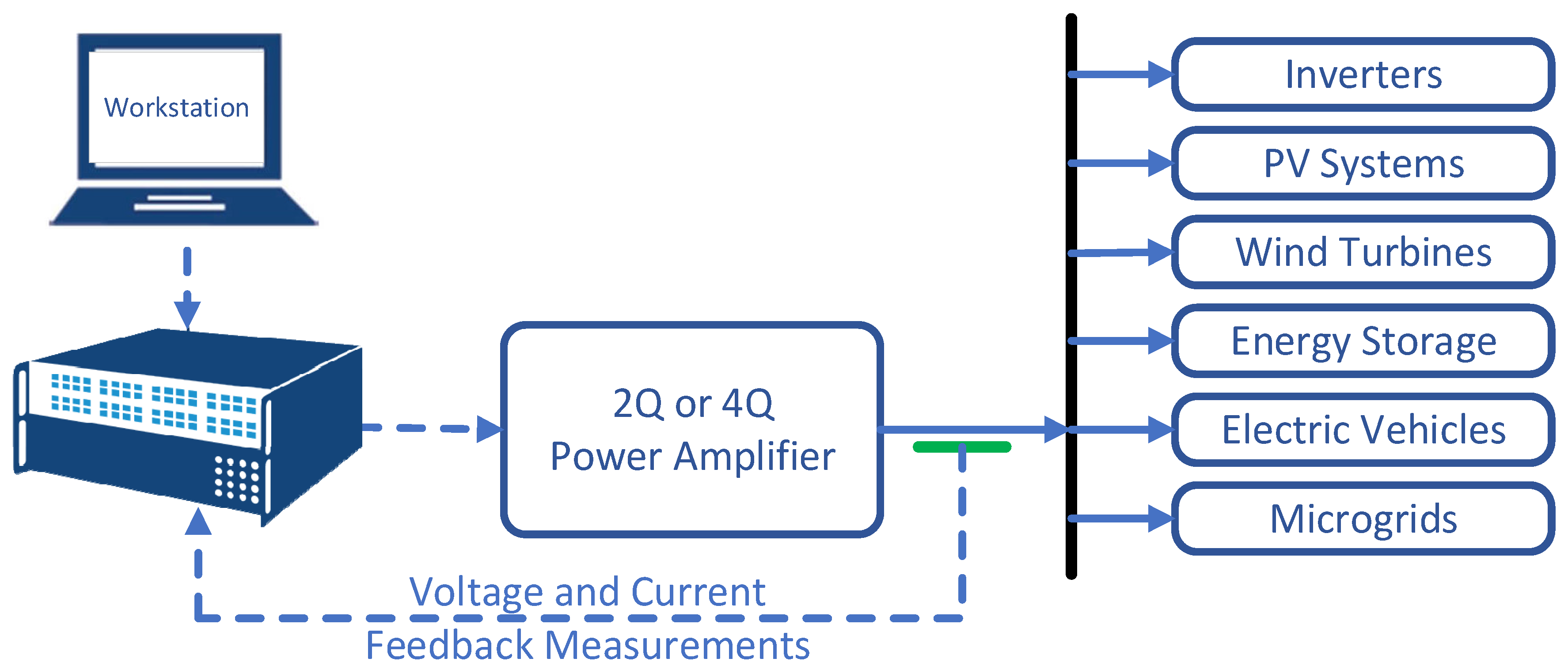
PHIL simulations are an extension of CHIL, where beyond low-voltage/low-current signals, the real-time simulation environment is capable of also transmitting the rated power required by the DUT [56,57]. To enable this bridge, power amplifiers are inserted between the RTS and the DUT as shown in Figure 4, which must be selected carefully depending on the application [56,57]. The power amplifier amplifies the low voltage signal from the RTS representing the simulated voltage at the node in the power system simulation where the power hardware is connected to the actual voltages and currents so the DUTs can be connected at rated power [6].
Power amplifiers, presented in more detail in Section 3.2, are selected based on several factors including the DUT testing application requirements, closed-loop performance and their ability to generate and absorb power. The PHIL setup is typically more complex and higher cost than CHIL primarily due to the cost of the power amplifier and sensing hardware needed to close the loop, but much less expensive than full system testing and testing in the field which both have reduced flexibility and increased risk, especially when new equipment is being tested [56,57].

3. PHIL Setup Requirements and a Detailed Case Study

A typical PHIL setup as shown in Figure 5 includes an RTS with inputs and outputs, power amplifier(s), sensors for feedback to the RTS, real-time models, interface algorithms, filtering, compensation, protection, etc. [31,56,57]. The key factors for successful PHIL simulation are presented in this section, where the interface of the DUT with the power system simulation inside the RTS must be as seamless as possible such that the DUT doesn’t recognize it is actually interfaced to a simulated power system software model [56,57].

3.1. Real-Time Simulation Requirements

It is important to understand the type of simulation behind real-time HIL testing. The type of simulation is chosen based on the phenomena of interest for a particular study. For example, for power system load flow a quasi-steady-state analysis is adequate and would provide phasors around the fundamental frequency as an output on a timescale of seconds to minutes [57]. However, quasi steady-state analysis lacks the ability to capture sub-cycle phenomena associated with transients and to represent low level controls of inverter-based systems. Electromagnetic transient (EMT) algorithms were first introduced by Dommel in the creation of the Electromagnetic Transients Program EMTP in 1969 [60], using nodal analysis and applying numerical techniques to convert the differential equations representing the power system network into algebraic equations. Application of the programmed simulation model requires a simulation time step, and a new system state is computed every simulation time step, which includes the solution of the network’s node voltages and component branch currents [57]. Historically, in the electric power industry, models were created using EMTP and “run in real time to simulate primary equipment such as generators, transformers, conductors, cables, and loads, where the models provide real-time responses to faults, disturbances, load changes, and controller or protection actions” [8].
While EMT simulation captures the underlying fast-transient (tens of microseconds) behavior of the system, the significant computational requirements limit the system size that can be modeled [7]. Real-time operation can be performed for simple systems by using high speed processors, however, as the system size increases, the simulation time step becomes too large for the simulation to converge to an accurate result [57]. To simulate large electric grids while keeping the simulation time step sufficiently small, the Manitoba HVDC Research Center developed the real-time digital simulator (RTDS) in 1993 [61].
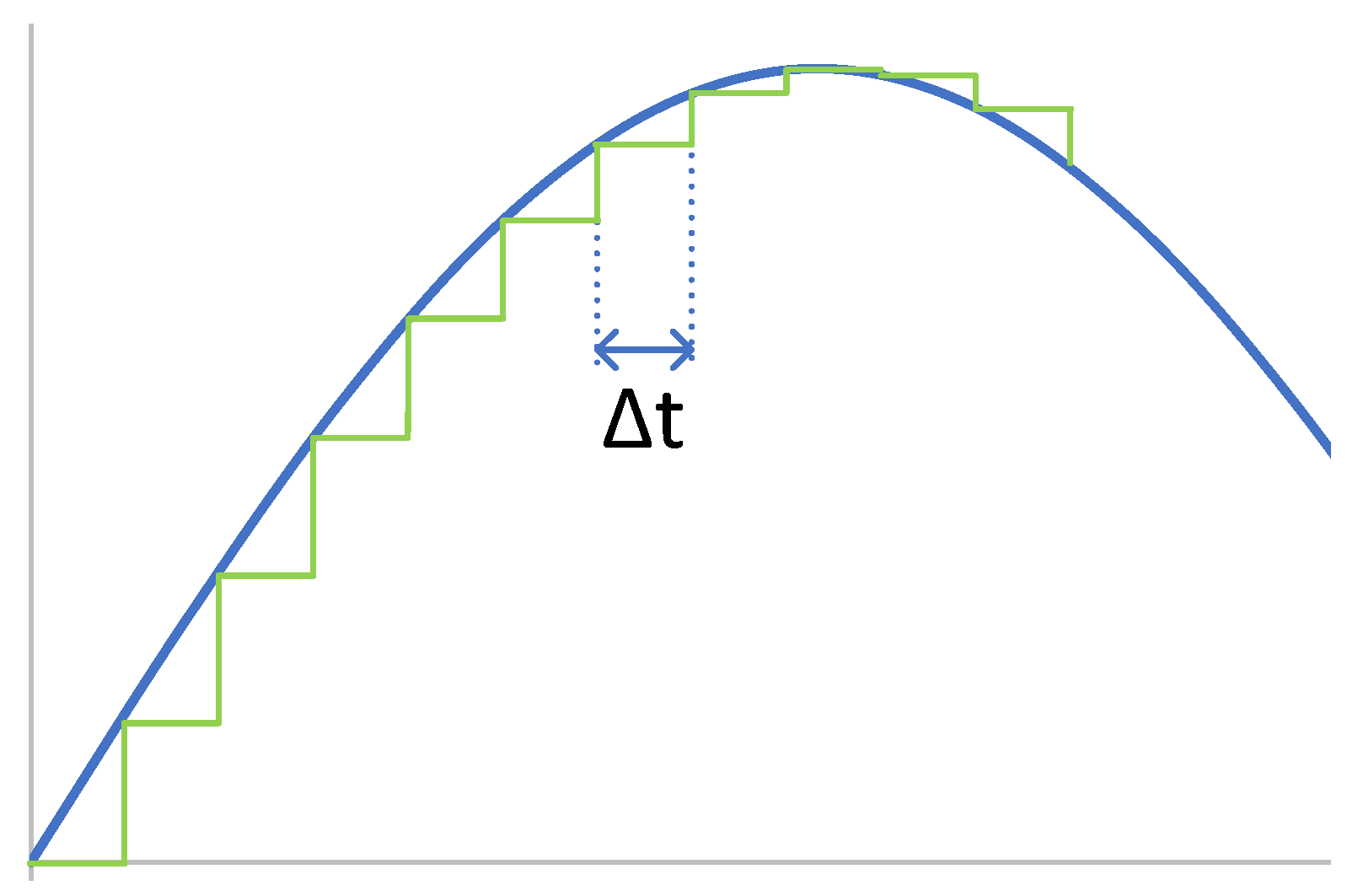
An RTS uses EMT algorithms to provide time varying instantaneous value outputs as shown in Figure 6 [57]. Thus, the outputs match the voltage and current waveforms as if they were measured from the actual system which allows a much greater depth of analysis over a wide frequency range, and the ability to reproduce fast transients on the power system [57]. The higher the sampling frequency of the simulation, the higher frequency results that can be accurately reproduced. The period of that sampling frequency, or the distance between two consecutive outputs, is in fact the simulation time step or Δt as shown in Figure 6. The size of the time step dictates the frequency range over which the simulation results are valid and how frequently data is transmitted and received in the RTS. Standard EMT timesteps are in the 25–50 µs range; however, if one is interested in representing the high frequency switching behavior of power electronics in the tens of kHz range, the timestep needs to be reduced to the 1–3 µs range [57]. At every timestep, the RTS running the simulated power system sends the output set-point to the power amplifier, which changes the set-point information received into actual voltage or current, and the DUT reacts to the new value [52]. This DUT reaction is measured by the power amplifier and by the RTS sensors, including it in the simulation model to calculate the next step [52].
For a real-time simulation to be valid, the simulation used must accurately produce the outputs within the same length of time as the physical counterpart of the real-world system [56]. The time necessary to compute the solution at a given time step must be less than the “wall clock” duration of the time step as shown in Figure 7 [56]. For example, a 3-cycle fault for a 60 Hz system is 0.05 s, thus an RTS simulates this fault in real-time, i.e., 0.05 s [57]. This permits the real-time simulation to perform all operations necessary including driving the I/Os needed for the HIL system. For offline EMT programs, e.g., running on PCs rather than on dedicated real-time parallel processing simulation hardware, the time to complete these simulations is much greater, and thus prevents the ability to connect external hardware to the simulation to test in real time in a closed-loop [56,57].
PHIL uses EMT simulations running on RTSs and adds actual hardware, e.g., IBRs, at rated power in combination with real-time simulation of the electric grid [7,56,57]. A real-time simulation running on an RTS dedicated parallel processing simulation hardware allows the connection of physical devices in a closed-loop with the simulated environments. Closing the loop means not only observing the response of the device to an imposed signal, but also interfacing that devices response back into the simulated network. This type of HIL testing is only possible when updating the inputs and outputs of the simulation continuously in real time and is not possible with an offline simulation or with open-loop testing tools [56,57].
The RTSs that have been commonly used in PHIL applications in recent years to simulate an electric grid with a high number of nodes in real-time are given below along with example published papers [52]:
-
OPAL-RT [56,62,63,64,65,66,67,68,69,70,71,72,73,74,75,76,77];
-
-
HYPERSIM [104,105,106].
Note, HYPERSIM was developed by Hydro-Québec and is now also available from OPAL-RT Technologies which spring-boarded out of Hydro-Quebec [56].

3.2. Power Amplifier Hardware Interface Requirements

As noted, in PHIL testing a power amplifier is required to amplify the low voltage and current signals from the real-time system simulation to the actual voltages and currents so the DUTs, e.g., DER inverters, can be interfaced at rated power. In closed-loop operation the DER output to the power amplifier is measured and fed back to the power system simulator model to close the loop and influence the simulation.
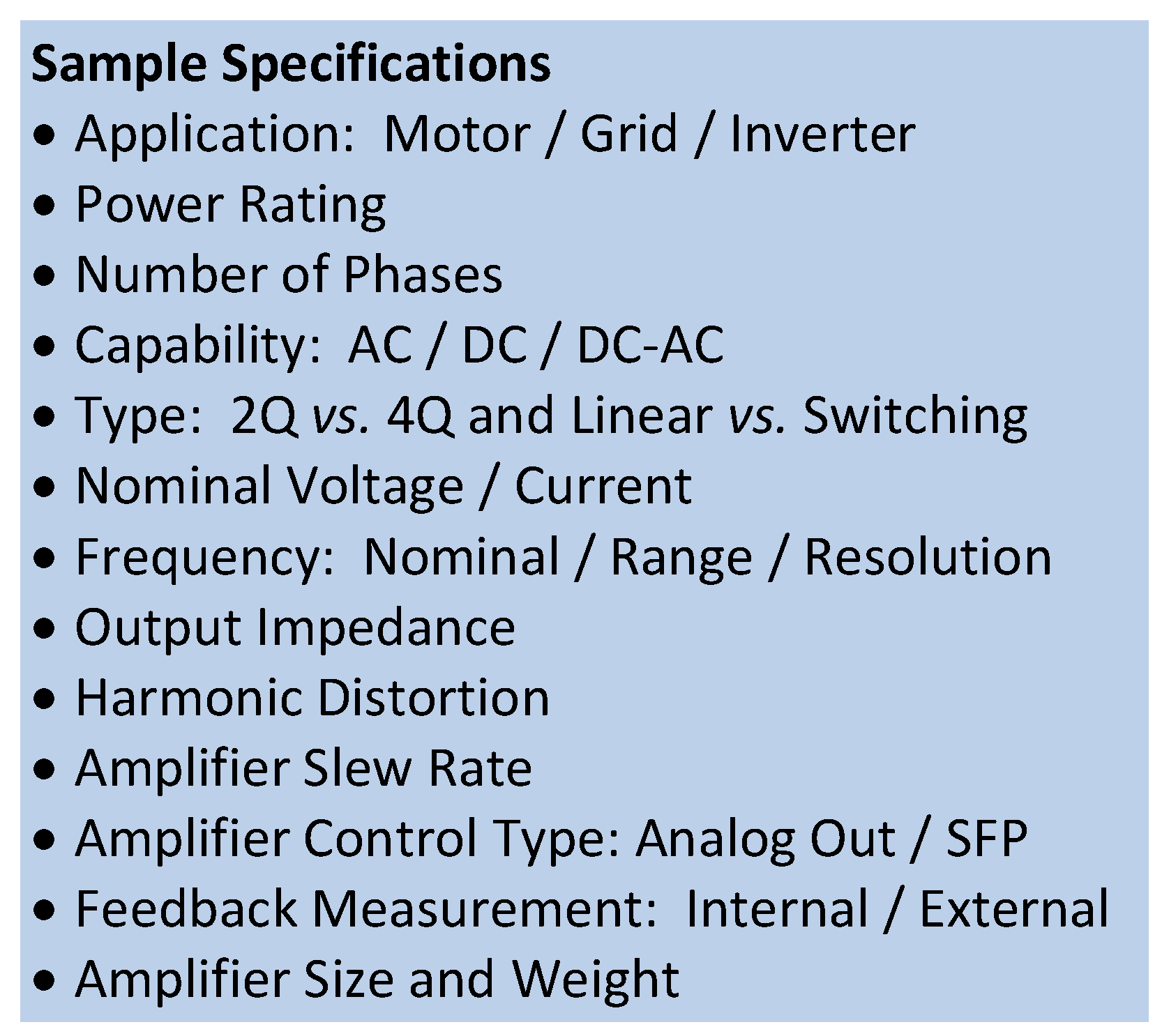
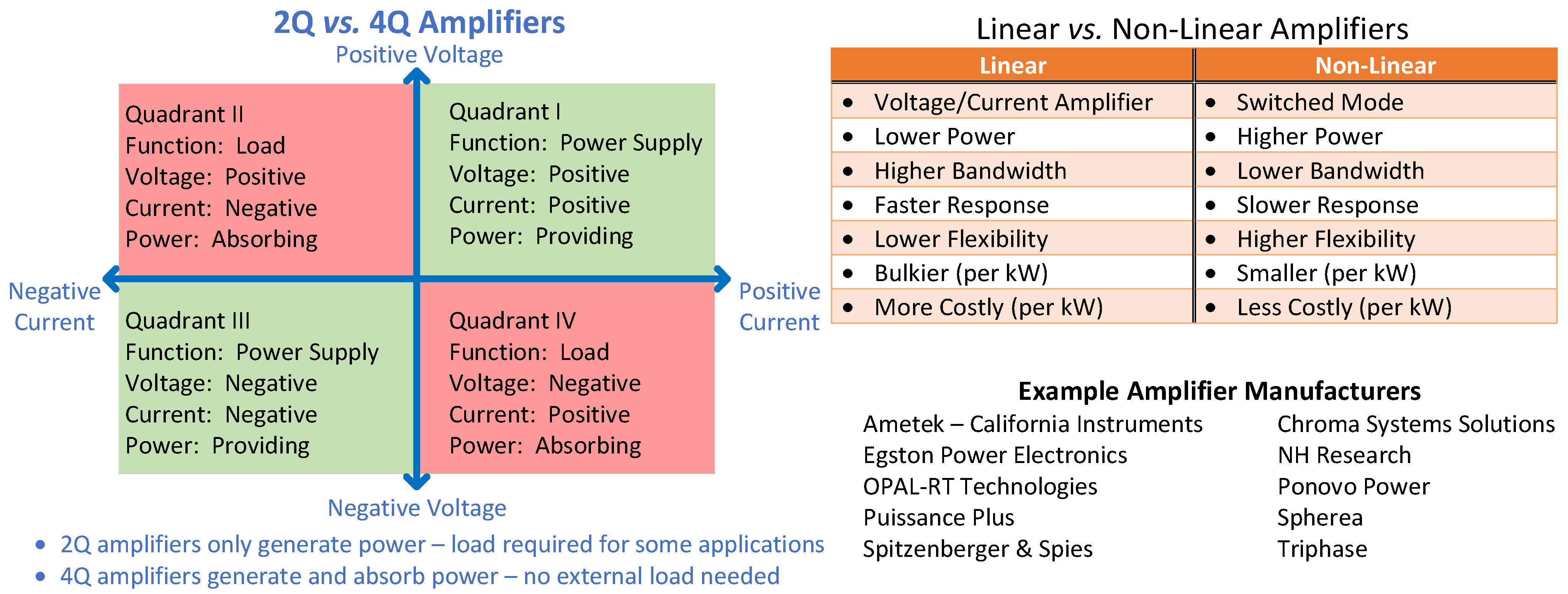
The power amplifier selection is technical, with sample specifications shown at the top of Figure 8, with the foundational specification being the overall application type [56]. Other important aspects of the specifications are the power rating, the number of phases, what type of capabilities are needed for the simulation, e.g., AC or DC, or DC to AC etc. Also important is whether a two quadrant (2Q) or four quadrant (4Q) amplifier is necessary as shown in the middle of Figure 8. 2Q amplifiers can only source (generate) power to the DUT whereas 4Q amplifiers can operate in all four quadrants of the power plane and thus can both source and sink active and reactive power. For closed-loop PHIL simulations, the amplifier is required to operate in all four quadrants of the power plane [56,57]. When 2Q amplifiers are employed, depending on the application, they may require additional sinks/loads between the amplifier and the inverter because the DUT (e.g., PV inverter) power would need to go somewhere and the amplifier cannot sink the power [56,57]. Overall, the 4Q power amplifier acts like a grid simulator and reproduces/amplifies the voltages on the real-time simulated network and interfaces/absorbs power from devices. Another critical detail is that some amplifiers are designed to absorb 100% of their rated power when operating in sink mode but some cannot, so one must be careful when specifying the amplifier, e.g., the amplifier must have the capability to feed the device under test and to absorb the full power generated by the device [56].
Other specifications included on the left side of Figure 8 are self-explanatory, though of importance to mention is that the power amplifier slew rate is how fast the amplifier responds when a set point is sent to the amplifier [56]. As shown in the upper right of Figure 8, amplifiers used in PHIL applications have been linear and non-linear (switched) types with the characteristics of each listed [56]. Currently, non-linear switched amplifiers are predominantly implemented due to the fact that they are more efficient with higher power densities and can be more easily connected in higher power applications [56]. Example amplifier manufactures are given in the lower right of Figure 8.
The bandwidth of the power amplifier represents the frequency range that the amplifier can amplify the input signal [57]. The selected amplifier should have adequate bandwidth to amplify the input signal over the frequencies of interest with minimum harmonic distortion [57]. The power amplifier bandwidth/frequency range determines the data rate, or amount of data transferred per second where (0–2 kHz) is considered a suitably high bandwidth for power systems PHIL [106] as further detailed below. In the testing design process, the highest frequency in the model that has to be closed-loop controlled must be determined, which will define what the simulated model bandwidth is [107]. To simulate an electric grid transient, a maximum frequency of 2 kHz is usually taken [108]. To ensure the PHIL setup can achieve the desired frequency, the procedure detailed in [107] can be followed which provides the model cycle time, the power analyzer bandwidth and the maximum open delay depending on the closed-loop controlled model frequency [52] as will be further described in Section 3.3.3 on stability and accuracy.
Currently, PHIL testing is primarily voltage-type, e.g., where the power amplifier operates as a voltage source. This is mainly because the majority of DUTs are current sources such as renewables-based DERs using grid-following inverters [52]. Grid-following inverter control regulates active and reactive power output and ties into the grid to match the local voltage and frequency and requires a voltage reference to synchronize their internal phase locked loop (PLL) [109,110,111]. This makes grid-following inverters well-suited for grid-tied operation, but not under islanded conditions as they do not provide grid-forming capabilities needed to sustain microgrids [109]. If the DUT is a grid-following inverter, the PLL of the inverter uses the power amplifier voltage as an angle reference to synchronize the phase angle of the inverter terminal voltage [109]. Once the grid-following inverter is synchronized with the power amplifier, the inverter can provide the commanded real and reactive powers [109]. Thus, if the PHIL test is voltage-type, e.g., a grid-following PV inverter, the amplifier operates as a voltage source and the RTS sends the voltage set-point to the amplifier and measures the current response of the DUT as in [7].
If the PHIL test is current-type, e.g., a grid-forming inverter, the amplifier acts as a current source, thus the RTS sends the current set-point to the amplifier and measures the voltage response of the DUT as in [109]. Note, in [109] an inductor is used between the grid-forming inverter and the amplifier to enable current-source amplifier operation. Some PHIL power hardware, such as PV and battery inverters, require a DC power input, e.g., provided by a controllable DC source [7]. In addition, a DUT such as a PV inverter may be interfaced on its AC side through a transformer to the power amplifier to match the voltage levels of the solar PV inverters and the grid voltages passed to the amplifier as in [6,7]
In most of the literature on PHIL testing for DER integration, the DUTs and their controls are tested in a PHIL environment, not amplifiers [112]. In [112] the authors focus on a power amplifier in current-controlled mode as the actual DUT which could enable the effective use of amplifiers as hardware emulators for DERs in future PHIL integration studies.

3.3. Interface Algorithms, Communications, Stability and Coordination Considerations for PHIL Testing

3.3.1. Interface Algorithms

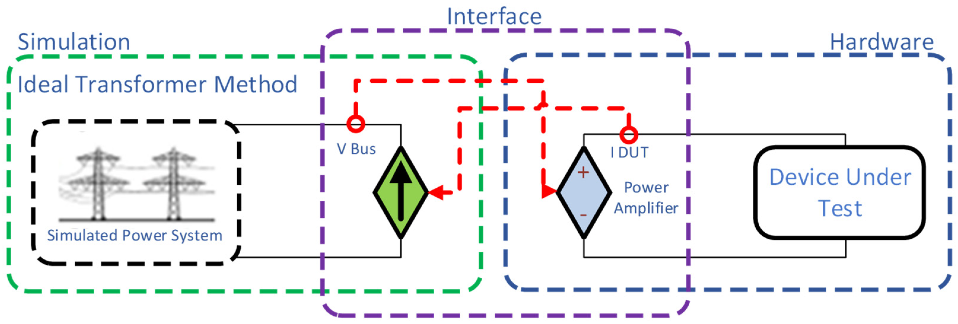
The methodology of the interface determines which signals are exchanged between the RTS and the external equipment, as well as the timing of those exchanges during the simulation timestep [57]. Different types of interface algorithms can be implemented on the RTS to interface between the power system simulation and the hardware including the ideal transformer model (ITM), the damping impedance method (DIM), the transmission line model (TLM), the partial circuit duplication (PCD), and the time-variant first-order approximation (TFA) [17,98,113]. The most commonly used model is (the ITM shown in Figure 9) popular because of its accuracy, low computation requirements, ease of implementation, and because closed-loop stability can be achieved easily by damping the system [52,53,54,98].
The ITM works on voltage (or current) amplification and current (or voltage) feedback [57]. In this methodology, the RTS sends the voltage/current to the amplifier immediately (or as soon as possible) after the voltage/current is computed and initiates the current/voltage read just before it is needed for the EMT algorithm used in the simulator’s network solution [57]. Therefore, the delay is not simply one simulation time step, but also must include any communication delays, power amplifier response characteristics and transducer characteristics, which also includes filters [57,112]. For example, as shown with the red dashed lines in Figure 9, the simulator will use the ITM to create the voltage signal for the amplifier which then presents as a voltage source for the DUT (e.g., a grid-following PV inverter) and then the inverter current measured by the amplifier is fed back to the simulated grid model to close the loop [57].

3.3.2. Communications and I/O

Interface I/O between the RTS and external equipment is either internal to the RTS or using network interface cards such as a DAC from the RTS to the amplifier and an ADC from the device under test to the RTS as shown in Figure 10 [57]. This I/O interface is created based on standard compliant communication network protocols which takes power systems simulation data and assembles it into standard compliant packets and sends those out via ethernet local area network and unpacks the inputs coming from devices under test [57]. The RTS can directly stream the following protocols: IEC 61850, PMU IEEE C37.118, DNP3, SCADA DNP3, Modbus, CAN, etc. [56,57]. More recently optical fiber, as mentioned with CHIL, is being implemented (Aurora Communication Protocol) for interfacing with selected power amplifier systems which would eliminate the need for conventional I/O and reduce loop delay and noise, promising improved stability and accuracy [57]. Note, PHIL testing enables the incorporation of real-world delays, latencies and cyber-events into the system-level validation [56,57]. The cyber-physical testbed for microgrids presented in [19] demonstrated through sample case studies how communication delays could impact microgrid controller performance and the operation of the electrical grid [56].

3.3.3. Stability and Accuracy

To ensure stable and accurate PHIL simulation, the interface must be designed with the proper compensation [31]. Stability analysis must be performed because closed-loop PHIL systems including simulations, amplifiers, and sensors can become unstable for certain operating conditions [30,31,32,33,34]. Instability may damage equipment or result in loss of simulation fidelity [32]. Thus, stability analysis of the entire closed-loop system must be performed including the power amplifier, the feedback sensors and the loads for each of the applications because the stability depends on the ratio of load power to short circuit power, type of load, damping of source impedance, bandwidth of the power amplifier, sampling frequency of the simulator, feedback filter bandwidth, etc. [56]. Various methods for stabilization can be found in [30,31,32,33,34,114]. It is important to note that determining the optimum interface and stabilization methods to ensure maximum system stability and accuracy must be performed on a case-by-case basis [30,31,32,33,34,114]. Each of the components that build up the interface described in this section will contribute imperfections to the interface which need to be taken into account to understand how they impact the simulation results. For example, DACs, amplifiers and transducers must be considered carefully as they introduce delay and noise and can impact the stability and accuracy of PHIL simulations [76,115]. In addition, noise due to sensors and electromagnetic interference (EMI) can create interface issues and introducing filters in the hardware or software can both mitigate the problems and create unwanted time delays and attenuation [76,115]. Thus, compensation algorithms are often required to mitigate filtering effects [30,31,32,33,34].
For designing and building a PHIL test bench to ensure the PHIL system can operate at the system performance requirements, e.g., stability, accuracy and desired frequency (as discussed in Section 3.2) the procedure described in [107] is proposed. This involves determining the model cycle time, the power amplifier bandwidth and the maximum open delay based on the desired closed-loop controlled model frequency. The authors in [107] state that the total open-loop phase shift at the desired frequency must be less than −75°. The open-loop phase shift is the sum of each subsystem maximum open delay ( D t X ) in the PHIL control chain and the power amplifier transfer function, which can be referenced in Figure 10 above. A phase margin at the desired frequency is necessary to guarantee stability, using a regulator with a pole located at the origin.
The equations provided in [107] to determine the open delay, the power amplifier bandwidth and the model cycle time are presented below.
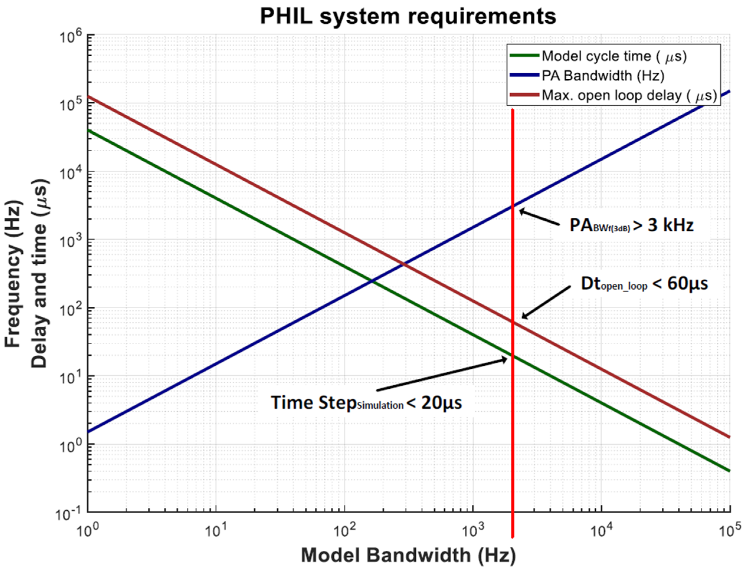
Maximum open delay:Figure 10 illustrates a PHIL setup where the setpoint and measurements are sent using an analog signal. The open-loop delay between the RTS output and input is the sum of each delay in the loop:
D t o p e n _ l o o p = D t D A C + D t P A + D t S e n s o r + D t A D C
The maximum delay between the output and the input to ensure an open-loop phase shift less than −45° must be:
D t o p e n _ l o o p < 45 ° 360 ° · f M o d e l B W = 1 8 · f M o d e l B W
Minimum power amplifier bandwidth: the open-loop phase shift at the power amplifier frequency bandwidth is −45°. To achieve an open-loop phase shift of −30°, the minimum bandwidth of the power amplifier must be at least 1.5 times wider than the highest frequency of the model to be simulated:
P A B W f ( 3 dB ) > 1.5 · f M o d e l B W
Model cycle time: The maximum time-step the simulator must achieve depends on the highest frequency bandwidth of the simulated model. In [107] it was determined that the minimum time step is required to be at least 25 times less than the inverse of the desired frequency:
T i m e _ S t e p S i m u l a t i o n < 1 25 · f M o d e l B W
Figure 11 below graphically depicts Equations (2)–(4) and illustrates an example of the characteristics needed to test a grid transient whose maximum frequency of interest is 2 kHz [52,107]. According to Equation (3), the minimum bandwidth of the power amplifier (“PA bandwidth” in Figure 11) is 3 kHz. Per Equation (4) the time step must be less than 20 µs, and according to Equations (1) and (2) the maximum open-loop delay must be less than 60 µs. These requirements are met for characteristics to the right of the red line in Figure 11.
For the PHIL test bench design and build, to make a more informed selection of PHIL elements, a deeper comparison of the solutions should be performed. This comparison should consider the main system characteristics such as the resolution of the ADC and DAC, types of communications, number of inputs/outputs and compatibility with other simulation systems [52]. When comparing different power amplifier systems, example factors that should be taken into consideration include the voltage and/or current bandwidth, slew rate, efficiency and current/voltage total harmonic distortion (THD). Fortunately, the decision between the different types of sensors is usually more straightforward considering the more mature technology. Overall, as emphasized throughout the Section 3 requirements, the RTS computational hardware must operate at a fast enough clock speed to accurately model the desired output time steps. The output sent to the DAC needs to have sufficient reliability. The power amplifier must accurately represent the desired signals and the sensor must accurately represent the quantities being measured, e.g., currents must be minimized and input impedances mut be high. In closing the loop, the ADC needs to be fast enough that the computations can be fed back at the specified rates.

3.3.4. Coordination, Data Management and Real-Time Visualization

Finally, test bed coordinator software can coordinate the interactions of the power system simulations as well as any devices and publish the data to a data management system and real-time visualization tool to capture and observe key parameters such as voltages, currents and powers around the PHIL system [11]. The test bed coordinator can employ the Hierarchical Engine for Large-scale Infrastructure Co-Simulation (HELICS), which is an open-source cyber-physical-energy co-simulation framework for electric power systems developed through the Grid Modernization Initiative of DOE [11,116].

3.4. PHIL Case Study

An example PHIL case study is given in [7], conducted by the National Renewable Energy Lab (NREL), where the objective was to test advanced distribution management system (ADMS) interactions with advanced PV inverters and particularly the impacts of reactive power control modes on the voltage profile of the feeder. As background, utilities use energy management systems (EMSs) for the transmission system and distribution management systems (DMSs) for the distribution system aiming to reduce outages and outage times (reliability) and maintain acceptable frequency and voltage levels (stability) [117]. These systems acquire grid information from SCADA systems providing real-time data every 2–4 s, now being enhanced by phasor measurement unit (PMU) monitoring devices measuring the instantaneous voltage, current, and frequency at much higher rates of 60 times per second [118]. ADMS includes advanced functions such as volt–volt ampere reactive (volt-VAR) optimization (VVO) where the ADMS controls inverters’ reactive power output as a function of voltage, fault location, isolation and system restoration (FLISR) and peak load management using dynamic voltage regulation (DVR) and demand-side management [11,119].
The NREL PHIL setup in [7], hardware shown in Figure 12, aimed to provide a combined hardware-software simulation of an electric distribution system grid with high DERs penetration that emulates a physical system sufficiently well that the performance of local advanced inverter controls vs. DMS coordination can be compared. To capture important DER operations across an entire distribution feeder, quasi-static time-series (QSTS) simulations were employed [7]. QSTS captures the slower (seconds to minutes) dynamics exhibited by variations in the DER output, load changes and standard distribution voltage control equipment [120]; however, the QSTS approach is inherently limited to slower phenomena and unable to capture potentially key fast interactions between the DERs and the grid [7].
The case study in [7] details a novel multi-rate, or multi-timescale, co-simulation architecture that integrates PHIL with a real-time QSTS simulation of a large distribution network by adding a reduced-equivalent EMT model of the distribution feeder to capture faster phenomena between the relatively slower time steps of the QSTS. This enables the Q-V interactions under volt-VAR control to settle before the QSTS time step advances. This co-simulation architecture overcomes the challenge of the slower time step (>1 s) of the QSTS simulation. The computation time of the QSTS may be as long as 30 s for some commercial DMS platforms, which is much slower than the inverter control bandwidth employed in PHIL, where the timesteps are typically set to the fastest rate at which the RTS can run without missing real-time steps (e.g., 50 µs) [7].
The multi-timescale simulation environment combined 4 cores of an OPAL-RT RTS running OPAL-RT’s EMT simulator eMEGASIM with a time step of 50 µs in co-simulation with a 4-core Windows virtual machine running the DMS and QSTS power system simulations at a larger time step (i.e., seconds). NREL used the phasor-based model capability of the DMS as the QSTS simulation to solve the full distribution feeder model, and the eMEGASIM tool to solve in real time a MATLAB Simulink-based reduced-equivalent EMT model of the distribution feeder. The EMT simulation of the reduced-equivalent feeder model and the PHIL interface to the hardware was run at a time step of 50 µs in the RTS. The QSTS simulation was performed on the DMS platform at a larger time step (i.e., seconds). Custom Python-based synchronization and pass-through code acted as a coordinator to inject the EMT data between the larger time step QSTS simulation.
The architecture comprises four main parts:
  • hardware, including an amplifier (540 kVA AC source) and the DUT (500 kVA PV inverter (AE500)), as shown in Figure 12;
  • QSTS simulation of the complete distribution feeder model in the DMS software on a 4-core Windows virtual machine;
  • OPAL-RT RTS (4 core) running a reduced-equivalent EMT model of the feeder in eMEGASIM and that also drives the hardware;
  • communications link between the DMS and the RTS that includes custom software to coordinate the QSTS and EMT simulations.
In addition to the PHIL simulation of the grid interacting with the DUT at the point of common coupling (PCC), a hardware PV simulator based on a DC amplifier that simulates the operation of the PV array at the DC side of the PV inverter is included. To do so, a PV model running in the RTS (based on the single diode model proposed in [121]) mimics the behavior of the PV array and sends a signal to the PV simulator amplifier. The PHIL interface was developed for evaluating grid-following PV inverters, and therefore an amplifier operating as a voltage source is used. The three-phase PV inverter is interfaced on the AC side through a transformer to the amplifier (to match the voltage levels of the solar PV inverter) and on the DC side to the PV simulator.
The amplifier is a controlled AC source whose output voltage waveform is controlled to represent the voltage at the PCC of the grid-tied PV system. The amplifier receives an analog voltage signal for the three phases through the RTS I/O interface at every EMT time step of 50 µs. The amplifier amplifies the aforementioned scaled-down PHIL voltage control signal to a 277 V nominal per-phase voltage signal. Then the AC current is measured at the amplifier and sent to the RTS through analog I/O to close the loop.
To conclude the case study, by employing a reduced-equivalent network model in the EMT simulation that replicated a subset of critical electrical connections, a PHIL simulation that could rapidly respond to volt-VAR control operations coupled to a larger QSTS simulation that maintained the full-system fidelity at slower time steps was developed. This enabled testing controls at different timescales, e.g., combining slower DMS and faster DERs with grid support functions. The architecture successfully captured PV local volt-VAR control interactions with the larger network under time-varying electrical and weather conditions.

4. Exemplary and Unique PHIL Testbed Developments around the World

Numerous PHIL power system testing platforms of various configurations and power ratings have been developed around the world. Six exemplary PHIL systems from four countries were selected, to provide representative coverage of unique system capabilities, and are briefly presented in alphabetical order based on published information to provide a more comprehensive picture of the role of PHIL in various power system applications.

4.1. Austrian Institute of Technology (AIT) PHIL Real-Time Simulation Activities

The Power Electronics Laboratory at AIT is set up allowing for maximum flexibility on low-inertia and microgrid research applications. This system includes back-to-back 4Q power converter devices featuring AC/DC in/output busses to study processes like the operation of battery systems and communication/power interfacing possibilities to real-time based PHIL simulation techniques [34,122].
Key equipment includes:
  • “Multiple sources/sinks ranging from high-bandwidth grid simulators/power amplifiers and AC/DC amplification units to an actual PV system
  • Specialized equipment for the development of Wide Band Gap (WBG) semiconductor applications
  • Multi-level single and three-phase power converter topologies for 4 quadrant converters (Ratings: 35 kVA AC, 35 kW DC/per device)
  • High-voltage programmable power supply (Rating: 10 kV)
  • Wide range of high-end, high-fidelity measurement equipment” [123]
  • The AIT SmartEST Lab Services include [124]:
  • “Testing of components and systems with simulated grids and primary energy sources
The technical specifications in the laboratory for the grid simulation/power amplifier include:
  • “3 independent laboratory grids with variable network impedances for up to 1000 kVA, flexible star point configuration and grounding systems
  • Voltage ratings from 300 V to 690 V
  • 2 independent high bandwidth grid simulators: 0 to 480 V 3-phase AC, 800 kVA
  • 3-phase balanced and unbalanced operation
  • Low Voltage Ride-Through (LVRT) capabilities” [125]

4.2. Florida State University (FSU) Center for Advanced Power Systems (CAPS)

The FSU-CAPS campus resources include a physical testbed that can test prototype motors and drives, power electronics converters, control systems and other power system components at ratings up to the 5 MW level. Real hardware is coupled with RTDS for real-time digital power system simulation and modeling [18,48,49,78,83,86,87,90,93,98,99,100,101,126].
Simulation and hardware testing are integrated, offering unique and strategic testing and demonstration opportunities. The large-scale RTDS computational capabilities enable the FSU-CAPS facility to provide accurate and detailed models of power system distribution architecture, components and control systems that may not be available or practical to assemble for component testing. The FSU-CAPS facility includes a 5 MW dynamometer and a 5 MW variable voltage converter designed for high-power waveform generation. In tandem with the RTDS, these devices allow users of FSU-CAPS to test their equipment in any environment that can be simulated.
The “advanced power systems testbed consists of a highly flexible, re-configurable 4.16 kV distribution system with a stiff connection through a dedicated 7.5 MVA service transformer to an adjacent utility substation 115:12.5 kV distribution transformer” [127]. This enables the ability to perform PHIL experiments with electrical equipment interacting with high-fidelity simulations, at power levels up to 5 MW.

4.3. Hydro-Quebec Development of a PHIL Infrastructure

Hydro-Quebec’s Research Institute (IREQ) developed their PHIL infrastructure capabilities due to the large-scale deployment of inverter-based DERs with sophisticated control systems integrated at the distribution level bringing new equipment onto the power system and new ways of operation and has an important impact on the transmission system and generation. This DER deployment is based on utilities like Hydro-Quebec validating their compliance with grid connection requirements, resilience, stability, compatibility with the grid and other systems.
IREQ has been developing a MW scale PHIL, utilizing real-time simulation using Hypersim [104], power amplifier and interface and the device under test [105]. A key part of the system is the interface between the real power voltage and current and the grid simulation, thus IREQ designed and built their own power amplifier and the interface to the real-time grid simulation [105]. They have sought to achieve very high-performance levels including high bandwidth (0–2 kHz), low latency, very stable and accurate operation for any grid conditions, where an ideal transformer cannot handle these operation requirements [128]. With this system the PHIL can produce any voltage dips and surges at frequencies ranging from DC to several kHz, study the interaction between equipment and various grid simulation models, connect HUTs to any virtual grid, develop and test future grid technologies and develop and validate detailed EMT simulation models.

4.4. Karlsruhe Institute of Technology (KIT) PHIL Testbed

The KIT Energy Lab 2.0 for large-scale research infrastructure for the investigation of future energy systems has two major laboratories with slightly different focus [54,129,130,131]. The high-power PHIL laboratory is used for multimodal development, testing and grid integration of new technologies. This involves mixed AC and DC grids and novel DC technologies within those grids, storage systems such as flywheels and hybrid equipment combining conventional technologies and supercapacitors and research on superconducting technologies. The lab is equipped with a 1 MVA power amplifier working at up to 1.5 kVDC as well as real time simulators from OPAL-RT and RTDS.
The second area is the Smart Energy System Control Laboratory which enables the real time simulation of future microgrids with a multitude of associated large-scale components. Those components include model households, charging infrastructure, different solar systems and a flexible switching for the interconnection of those systems and energy storage systems. Different grid scenarios can be designed including control and stability of autonomous grids and ancillary services.
Example PHIL experiments include real-time simulation of German low voltage (LV) grids with focus on detailed harmonic grid modeling. KIT also has an Energy Smart Home Lab which is a smart, automated residential building providing ancillary grid services, that contains typical household appliances as well as battery storage, PV, EV, a Combined Heat and Power (CHP) unit and a heat pump for grid integration studies and device testing.

4.5. National Renewable Energy Laboratory (NREL) PHIL Capabilities

NREL’s current PHIL capabilities include two megawatt-scale grid simulators: a configurable 2 MW grid simulator in the Energy Systems Integration Facility (ESIF) and a 7 MVA grid simulator at NREL’s Flatirons campus called the controllable grid interface. NREL is in the process of upgrading to a 20 MW controllable grid interface at the Flatirons campus. The NREL ADMS Test Bed was developed at the ESIF site in Golden, Colorado, to evaluate the capabilities and impacts of ADMS systems designed to monitor and control the distribution network efficiently and reliably [6,7,11,30,31]. The test bed, also highlighted in the Section 3.4 Case Study, provides utilities and vendors the opportunity to examine the performance of a specific distribution system under a wide range of conditions that can be simulated in a laboratory environment for specific applications. The platform can use actual grid-scale hardware up to 2 MW, large-scale distribution system models, and advanced visualization to simulate real-world scenarios for ADMS evaluation and experimentation under realistic conditions. The PHIL connects actual power system equipment such as PV and battery energy storage system (BESS) inverters, grid-edge devices, and legacy utility control and automation equipment to the lab’s simulated utility environment. With the PHIL setup, NREL researchers can test how actual equipment interacts with the ADMS at scale while also validating software models. NREL has also performed multiple PHIL experiments of microgrids at ESIF, evaluating microgrid controllers and/or advanced inverter controls [132,133].
NREL’s 7 MVA power electronic grid simulator (controllable grid interface) enables the testing of many active and reactive power control features including, “inertial response, primary and secondary frequency responses, and voltage regulation of wind and solar generators (as well as other renewable and conventional generation technologies, including energy storage) in a controlled medium-voltage grid environment” [134]. A strategic feature of the controllable grid interface is, “the ability to test the balanced and unbalanced fault ride-through characteristics of test articles under simulated grid conditions” [134]. In addition, this PHIL setup, “allows the real-time emulation of conditions that may exist in various types of power systems” [134]. Researchers can test using the controllable grid interface in controlled 13.2 kV medium-voltage conditions, the controls of any inverter-coupled or conventional generation technology that responds directly to grid conditions [134].

4.6. Sandia National Laboratories PHIL Research

Sandia’s Distributed Energy Technologies Laboratory (DETL) is a research facility designed for studying the integration of, “emerging energy technologies into new and existing electricity infrastructure to accommodate the increasing demand for clean, secure and reliable energy” [135]. Researchers at the DETL focus on generation, storage and load management technologies at levels ranging from single component through whole system. It is important to note that “DETL staff examine advanced materials, controls, and communications to enable safe and resilient distributed and renewable power systems infrastructure” [135]. The high flexibility of the lab grid enables researchers to evaluate energy resources and controllers under a wide range of conditions including, “solar irradiance variability, AC/DC protection schemes, high and low temperatures, power levels, and voltage and frequency regulation functionality in both grid-connected and microgrid configurations” [135].
The DETL provides power electronics testing capabilities including islanded and campus microgrids as well as scaled portions of utility feeders and the transmission infrastructure using PHIL implementation [109,136,137,138,139]. “DETL includes a 480 V, 3-phase microgrid, with interconnections to the utility grid and to various distributed energy resources including PV inverters, energy storage inverters with grid-forming capability, microturbines, fuel cells, reciprocating engine-generators, and electrical energy storage systems” [135].

5. PHIL Research Paradigm Considerations to Advance Smart Inverter-Based Grid-Edge Solutions

Considering the strengths of PHIL systems presented in this paper, including accuracy, versatility and flexibility, an increase in the demand for PHIL testing is foreseen in energy systems laboratories around the world to address the need for innovations in multiple areas of the smart grid. However, there are no clearly superior PHIL platform engineering solutions yet established to perform all the needed testing applications. For this reason, and considering the costs involved in PHIL, the greatest associated with the RTS and the power amplifier, laboratories need to develop clear objectives for their testing programs to determine the best solutions. This section is intended to help guide researchers with the objectives of developing versatile PHIL platforms for advancing smart inverters to enable more DERs and connected energy devices at the grid-edge while improving grid reliability, stability, resilience and security.
In view of the variety of PHIL component vendors and possible configurations, the authors suggest researchers develop specifications and requirements to share with prospective vendors including the scope of the planned and future testing, information about the testing and DUTs, description of the planned testing and the overall PHIL requirements. Section 3 included example RTS vendors and power amplifier vendors. Again, considering these are the primary cost and driving components, it would be prudent to share the specifications and requirements with the appropriate vendors. Based on the vendor responses regarding how they propose to contribute to the planned PHIL system, including component quotes, researchers can move forward to make the best engineering decisions regarding their PHIL system.
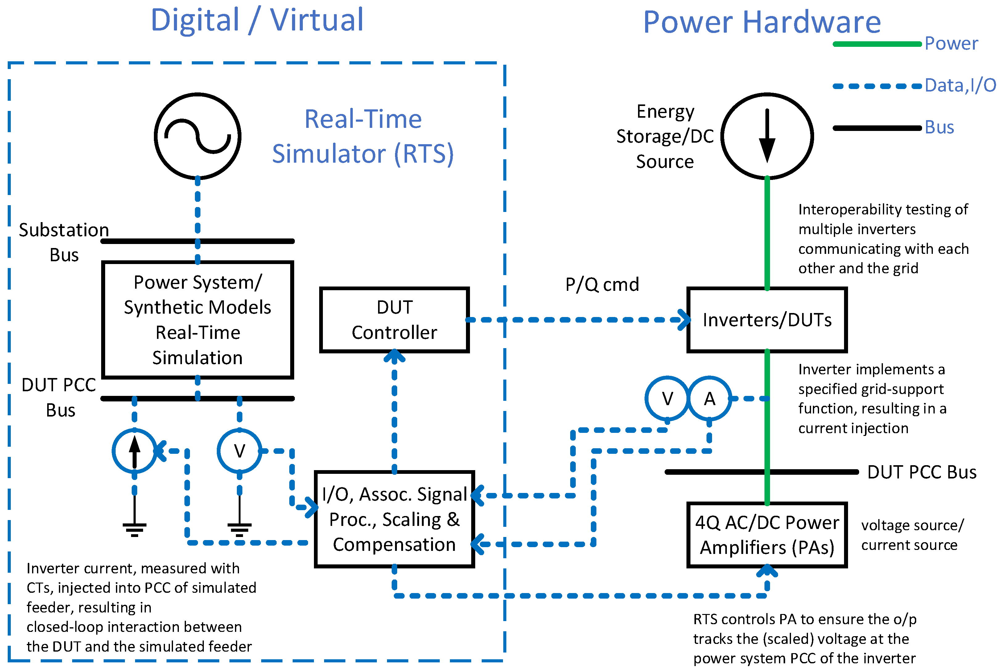
For the essential advancement of smart inverters for optimized integration of DERs the authors propose a specialized and versatile PHIL testbed design as shown in Figure 13 to enable the interoperability testing of multiple inverters (communicating with each other and the grid), emulating the integration and interaction of a combination of DERs, i.e., PV, battery energy storage and EVs, including both grid-following and grid-forming inverters. For grid-following inverters, an amplifier operating as a voltage source would be employed and smart functions could be optimized such as volt-VAR for voltage regulation, frequency-watt for frequency regulation, and constant power factor where the inverter is required to operate at a fixed PF or range of leading to lagging such that when the active power changes, the inverter will vary the reactive power output to ensure that the target PF is met [109]. Grid-forming inverters are a strong solution for microgrid islanded scenarios where power needs to be supplied while regulating voltage and frequency [109,110], and further PHIL testing is needing for advancement. For example, in a 100% inverter-based system, grid-forming inverters are needed to set the grid voltage and frequency [110]. For grid-forming inverters a current-source amplifier would be appropriate. Thus, amplifiers capable of operating as both a controlled voltage source and as a controlled current source as shown in Figure 13 would provide extended capability at an overall reduced cost, and thus would be included in the desired specifications.
The Universal Interoperability for Grid-forming Inverters (UNIFI) Consortium was launched in 2022, including multiple universities, national labs and industry members, to advance grid-forming inverters and identify challenges, where microgrids are seen as pilots for these new technologies [140]. PHIL testbeds would be strong solutions for these pilots where the interoperability of the inverters and the system can be fully researched according to grid codes and standards in addition to black-start capabilities. It is important to note that microinverters, typically dedicated to 1–4 solar modules, are also developing grid-forming capabilities and thus are important to consider in the proposed smart inverter research specifications. The PHIL testbed could include multiple lower power amplifiers with varying power capability, e.g., for microinverter and aggregation testing. Along these lines, a better understanding of how PV inverters and energy storage systems will behave in each electric grid is greatly needed [52], which is another strategic research thrust for PHIL platforms. EV fast charging impacts on grid and microgrids can also be researched including the use of local generation such as PV to support the grid. The proposed PHIL would also enable the ability to test the balanced and unbalanced fault ride-through characteristics of DUTs under simulated grid conditions.
As indicated in Section 3.2, application-specific power amplifiers can be configured to operate in either AC or DC mode. Amplifiers exhibiting AC or DC operation options provide extended capability for various PHIL applications and are thus recommended for the specification. Four quadrant amplifiers are also recommended due to the importance of closed-loop capabilities, enabling the DUT to also influence the simulation, and since the DUT may be absorbing or supplying power at different times during the test a 4Q amplifier is needed that can both source and sink power accordingly. Non-linear switched amplifiers are recommended due to their higher efficiencies and power densities and that they can be more easily connected in higher power applications. The recent innovation of fiber optic interfaces to eliminate the need for conventional I/O is another consideration for the specifications.
The inverter-based PHIL testbed will enable the evaluation of: microgrid control strategies, communication networks, interactions between loads and between grid-edge devices and the grid, behavior in adverse conditions, simulation models including synthetic models, all leading to advanced visualization techniques. A lab-scale microgrid could be considered or simulating a microgrid network on the RTS with a tie to a vendor microgrid controller. The testbed can further represent the present state of a specific distribution system using a digital twin, or the anticipated state when added DERs, such as rooftop PV systems, battery energy storage systems, EVs, loads with smart controls, etc., are included. Transmission energy management systems (EMS) may also be run on the RTS and interfaced with downstream distribution management systems such as a distributed energy resource management systems (DERMS) and interfaced with actual DERs.
This testbed would advance testing of high-performance autonomous inverter operation, where they will respond to local measurements with or without input from a remote operator and follow standard rules to fulfil their individual goals and collaborate (collaborative control) to sustain the grid. As stated in [141], most grid-tied inverters in the North American grid since 2003 have been listed under UL 1741, “Standard for Inverters, Converters, Controllers and Interconnection System Equipment for Use with Distributed Energy Resources” [141]. This UL 1741 standard was harmonized with IEEE 1547 for both grid-tied and non-grid-tied inverters, to yield a family of standards regarding performance, operation, testing, safety, and maintenance for DERs connected to the distribution grid [141]. The PHIL specification contributions could include supporting standards development for smart inverter functionalities and for analyzing the impacts of smart inverters on distribution systems.
A downside to these advanced inverter communications is increased cybersecurity risk, where with every DER communicating with the grid, this greatly increases the size of the “attack surface” [16,46,102]. PHIL testbeds can provide another level of cybersecurity risk emulation by enabling research on cyber intrusions in the communication network, such as event buffer flooding [142], man-in-the-middle [143], packet sniffing and modification [144] where the power system impacts can be observed with real-time simulation [46] on both the network and the hardware. Hardware devices such as smart inverters can detect the cyber security events with pre-defined alerts and control logic [46] to ensure the risk is minimized as inverters and the grid get smarter. Finally, the PHIL platform can enhance multiple cost-benefit analyses and case studies.

6. Conclusions

This paper review explored the role of PHIL for power system modernization, to enable the integration of more inverter-based DERs such as solar, wind, energy storage and EVs as well as emerging energy technologies. The stepped-process development of HIL, CHIL and PHIL systems for power systems applications was detailed through a comprehensive literature review, where CHIL was presented as a class of HIL simulation that allows the evaluation of hardware controllers through integration with software simulations.
PHIL systems were thoroughly described as a combination of both real-time simulation and hardware testing at rated power in a closed-loop configuration. Requirements and recent advancements for PHIL were presented including RTSs, power amplifiers, interfaces and communication and stability considerations to achieve good test fidelity. To strengthen understanding and appreciation of the presented PHIL concepts an illuminating case study was summarized to tie all the infrastructure details together. Numerous PHIL power system testing platforms of various configurations and power ratings have been developed around the world and six exemplary PHIL systems were presented from four countries to provide representative coverage of unique system capabilities.
The paper closes with a proposed PHIL research paradigm for accelerating the advancement of smart inverters for optimized integration of DERs to improve grid reliability, stability, resilience and security, and is summarized below:
  • Interoperability testing of multiple inverters and microinverters, communicating with each other and the grid according to standards (e.g., IEEE 1547), including both grid-following and grid-forming inverters;
  • Advance smart inverters providing grid services such as volt-VAR, frequency-Watt, constant PF, black-start capabilities, ride-through etc.
  • DERs testing with energy storage or headroom to rapidly increase/decrease output power to provide fast frequency response, address transients and controller interaction instabilities;
  • EV fast charging impacts on the grid and microgrids; use of local generation such as PV to support the grid;
  • Implement smart inverters optimized to respond based on grid conditions/measurements autonomously, follow standards with the priority to sustain the grid;
  • Evaluate control strategies, communication networks, interactions between loads and the grid and test behaviors in both normal adverse conditions;
  • Cybersecurity testing to emulate intrusions communications; observe behaviors of inverters detecting the cyber security events;
  • PHIL enables multiple cost-benefit analyses and case studies.

Author Contributions

Conceptualization, A.v.J.; methodology, A.v.J., E.A. and A.Y.; investigation, A.v.J., E.A. and A.Y.; resources, A.v.J., E.A. and A.Y.; writing—original draft preparation, A.v.J.; writing—review and editing, A.v.J., E.A. and A.Y.; visualization, A.v.J., E.A. and A.Y.; supervision, A.v.J., E.A. and A.Y. All authors have read and agreed to the published version of the manuscript.

Funding

This research received no external funding.

Data Availability Statement

Not applicable.

Conflicts of Interest

The authors declare no conflict of interest.

References

  1. IEEE Std. 1547.7-2013; IEEE Guide for Conducting Distribution Impact Studies for Distributed Resource Interconnection. IEEE Std.: New York, NY, USA, February 2014.
  2. U.S. Department of Energy. Smart Grid Systems Report; U.S. Department of Energy: Washington, DC, USA, January 2022.
  3. Siano, P. Demand response and smart grids—A survey. Renew. Sustain. Energy Rev. 2014, 30, 461–478. [Google Scholar] [CrossRef]
  4. Anttila, S.; Döhler, J.S.; Oliveira, J.G.; Boström, C. Grid Forming Inverters: A Review of the State of the Art of Key Elements for Microgrid Operation. Energies 2022, 15, 5517. [Google Scholar] [CrossRef]
  5. Strasser, T.; Pröstl Andrén, F.; Lauss, G.; Bründlinger, R.; Brunner, H.; Moyo, C.; Seitl, C.; Rohjans, S.; Lehnhoff, S.; Palensky, P.; et al. Towards holistic power distribution system validation and testing—An overview and discussion of different possibilities. E&I Elektrotechnik Inf. 2017, 134, 71–77. [Google Scholar]
  6. Bethany, S.; Dheepak, K.; Annabelle, P.; Mark, R.; Hongyu, W. Hardware-in-the-Loop (HIL) Simulations for Smart Grid Impact Studies. In Proceedings of the IEEE PES General Meeting, Portland, OR, USA, 5–9 August 2018. [Google Scholar]
  7. Prabakar, K.; Palmintier, B.; Pratt, A.; Hariri, A.; Mendoza, I.; Baggu, M. Improving the Performance of Integrated Power-Hardware-in-the-Loop and Quasi-Static Time-Series Simulations. IEEE Trans. Ind. Electron. 2021, 68, 10938–10948. [Google Scholar] [CrossRef]
  8. Scott, M.; Abdel Rahman, K.; Niannian, C.; Siddharth, S.R. Advantages of Real-Time Closed-Loop Simulation. In Proceedings of the IEEE Petroleum and Chemical Industry Technical Conference, San Antonio, TX, USA, 13–16 September 2021. [Google Scholar]
  9. Isermann, R.; Schaffnit, J.; Sinsel, S. Hardware-in-the-Loop Simulation for the Design and Testing of Engine-Control Systems. Control. Eng. Pract. 1999, 7, 643–653. [Google Scholar] [CrossRef]
  10. Bacic, M. On Hardware-in-the-Loop Simulation. In Proceedings of the 44th IEEE Conference on Decision and Control, Seville, Spain, 12–15 December 2005; pp. 3194–3198. [Google Scholar]
  11. Pratt, A.; Baggu, M.; Ding, F.; Veda, S.; Mendoza, I.; Lightner, E. A Test Bed to Evaluate Advanced Distribution Management Systems for Modern Power Systems. In Proceedings of the IEEE EUROCON 2019—18th International Conference on Smart Technologies, Novi Sad, Serbia, 1–4 July 2019; pp. 1–6. [Google Scholar] [CrossRef]
  12. Barragán-Villarejo, M.; García-López, F.D.P.; Marano-Marcolini, A.; Maza-Ortega, J.M. Power System Hardware in the Loop (PSHIL): A Holistic Testing Approach for Smart Grid Technologies. Energies 2020, 13, 3858. [Google Scholar] [CrossRef]
  13. Mariachet, J.E.; Matas, J.; Martín, H.; Li, M.; Guan, Y.; Guerrero, J.M. A power calculation algorithm for single-phase droop-operated-inverters considering linear and nonlinear loads HIL-assessed. Electronics 2019, 8, 1366. [Google Scholar] [CrossRef] [Green Version]
  14. Huo, Y.; Gruosso, G. Ancillary service with grid connected PV: A real-time hardware-in-the-loop approach for evaluation of performances. Electronics 2019, 8, 809. [Google Scholar] [CrossRef] [Green Version]
  15. Sun, C.; Paquin, J.; Al Jajeh, F.; Joos, G.; Bouffard, F. Implementation and CHIL Testing of a Microgrid Control System. In Proceedings of the 2018 IEEE Energy Conversion Congress and Exposition (ECCE), Portland, OR, USA, 23–27 September 2018; pp. 2073–2080. [Google Scholar] [CrossRef]
  16. Choi, J.; Narayanasamy, D.; Ahn, B.; Ahmad, S.; Zeng, J.; Kim, T. A Real-Time Hardware-in-the-Loop (HIL) Cybersecurity Testbed for Power Electronics Devices and Systems in Cyber-Physical Environments. In Proceedings of the 2021 IEEE 12th International Symposium on Power Electronics for Distributed Generation Systems (PEDG), Chicago, IL, USA, 28 June–1 July 2021; pp. 1–5. [Google Scholar] [CrossRef]
  17. Lauss, G.F.; Faruque, M.O.; Schoder, K.; Dufour, C.; Viehweider, A.; Langston, J. Characteristics and Design of Power Hardware-in-the-Loop Simulations for Electrical Power Systems. IEEE Trans. Ind. Electron. 2016, 63, 406–417. [Google Scholar] [CrossRef]
  18. Steurer, M.; Bogdan, F.; Ren, W.; Sloderbeck, M.; Woodruff, S. Controller and Power Hardware-in-the-Loop Methods for Accelerating Renewable Energy Integration. In Proceedings of the 2007 IEEE Power Engineering Society General Meeting, Tampa, FL, USA, 24–28 June 2007. [Google Scholar]
  19. Lundstrom, B.; Chakraborty, S.; Lauss, G.; Brundlinger, R.; Conklin, R. Evaluation of System-Integrated Smart Grid Devices using Software and Hardware-in-the-Loop. In Proceedings of the 2016 IEEE Innovative Smart Grid Technologies Conference (ISGT), Minneapolis, MN, USA, 6–9 September 2016. [Google Scholar]
  20. Guillaud, X.; Faruque, M.O.; Teninge, A.; Hariri, A.H.; Vanfretti, L.; Paolone, M.; Davoudi, A. Applications of real-time simulation technologies in power and energy systems. IEEE Power Energy Technol. Syst. J. 2015, 2, 103–115. [Google Scholar] [CrossRef] [Green Version]
  21. Alam, S.; Banerjee, A.; Mosier, T. Power Hardware-In-the-Loop Hydropower and Ultracapacitor Hybrid Testbed. In Proceedings of the 2022 IEEE Power & Energy Society General Meeting, Denver, CO, USA, 17–21 July 2022; pp. 1–5. [Google Scholar]
  22. Vogel, S.; Stevic, M.; Kadavil, R.; Mohanpurkar, M.; Koralewicz, P.; Gevorgian, V.; Monti, A. Distributed real-time simulation and its applications to wind energy research. In Proceedings of the 2018 IEEE International Conference on Probabilistic Methods Applied to Power Systems (PMAPS), Boise, ID, USA, 24–28 June 2018; pp. 1–6. [Google Scholar]
  23. Nelson, A.; Nagarajan, A.; Hoke, A.; Prabakar, K.; Gevorgian, V.; Lundstrom, B.; Nepal, S.; Asano, M.; Ueda, R.; Shindo, J.; et al. Hawaiian Electric Advanced Inverter Grid Support Function Laboratory Validation and Analysis; Technical Report NREL/TP-5D00-67485; NREL: Golden, CO, USA, 2016. [Google Scholar]
  24. Nelson, A.; Prabakar, K.; Nagarajan, A.; Nepal, S.; Hoke, A.; Asano, M.; Ueda, R.; Ifuku, E. Power hardware-in-the-loop evaluation of PV inverter grid support on Hawaiian Electric feeders. In Proceedings of the 2017 IEEE Power & Energy Society Innovative Smart Grid Technologies Conference (ISGT), Washington, DC, USA, 23–26 April 2017; pp. 1–5. [Google Scholar]
  25. Huerta, F.; Tello, R.L.; Prodanovic, M. Real-time power-hardwarein-the-loop implementation of variable-speed wind turbines. IEEE Trans. Ind. Electron. 2017, 64, 1893–1904. [Google Scholar] [CrossRef]
  26. Kelper, B.D.; Dessaint, L.A.; Al-Haddad, K.; Nakra, H. A comprehensive approach to fixed-step simulation of switched circuits. IEEE Trans. Power Electron. 2002, 17, 216–224. [Google Scholar] [CrossRef]
  27. Dufour, C.; Abourida, S.; Belanger, J.; Lapointe, V. InfiniBand based real-time simulation of HVDC, STATCOM, and SVC devices with commercial-off-the-shelf PCs and FPGAs. In Proceedings of the IECON 2006-32nd Annual Conference on IEEE Industrial Electronics, Paris, France, 7–10 November 2006; pp. 5325–5331. [Google Scholar]
  28. Majumder, R.; Pal, B.C.; Dufour, C.; Korba, P. Design and realtime implementation of robust FACTS controller for damping interarea oscillation. IEEE Trans. Power Syst. 2006, 21, 809–816. [Google Scholar] [CrossRef] [Green Version]
  29. Sybille, G.; Giroux, P. Simulation of FACTS controllers using the MATLAB power system blockset and hypersim real-time simulator. In Proceedings of the 2002 IEEE Power Engineering Society Winter Meeting, New York, NY, USA, 27–31 January 2002; Volume 1, pp. 488–491. [Google Scholar]
  30. Wang, J.; Lundstrom, B.; Mendoza, I.; Pratt, A. Systematic Characterization of Power Hardware-in-the-Loop Evaluation Platform Stability. In Proceedings of the 2019 IEEE Energy Conversion Congress and Exposition (ECCE), Baltimore, MD, USA, 29 September–3 October 2019; pp. 1068–1075. [Google Scholar] [CrossRef]
  31. Ainsworth, N.; Hariri, A.; Prabakar, K.; Pratt, A.; Baggu, M. Modeling and compensation design for a power hardware-in-the-loop simulation of an AC distribution system. In Proceedings of the 2016 North American Power Symposium (NAPS), Manhattan, KS, USA, 18–20 September 2016; pp. 1–6. [Google Scholar] [CrossRef]
  32. Kashani, M.G.; Pulakhandam, H.; Bhattacharya, S.; Katiraei, F.; Kaiser, D. Design considerations and test setup assessment for power hardware in the loop testing. In Proceedings of the 2017 IEEE Industry Applications Society Annual Meeting, Cincinnati, OH, USA, 1–5 October 2017; pp. 1–8. [Google Scholar] [CrossRef]
  33. Ebe, F.; Idlbi, B.; Stakic, D.E.; Chen, S.; Kondzialka, C.; Casel, M.; Heilscher, G.; Seitl, C.; Bründlinger, R.; Strasser, T.I. Comparison of power hardware-in-the-loop approaches for the testing of smart grid controls. Energies 2018, 11, 3381. [Google Scholar] [CrossRef] [Green Version]
  34. Lauss, G.; Strunz, K. Accurate and Stable Hardware-in-the-Loop (HIL) Real-Time Simulation of Integrated Power Electronics and Power Systems. IEEE Trans. Power Electron. 2021, 36, 10920–10932. [Google Scholar] [CrossRef]
  35. Xie, F.; McEntee, C.; Zhang, M.; Lu, N.; Ke, X.; Vallem, M.R.; Samaan, N. Networked HIL Simulation System for Modeling Large-scale Power Systems. In Proceedings of the 2020 52nd North American Power Symposium (NAPS), Tempe, Arizona, 11–13 April 2021; pp. 1–6. [Google Scholar] [CrossRef]
  36. De Carne, G.; Buticchi, G.; Liserre, M. Current-type Power Hardware in the Loop (PHIL) evaluation for smart transformer application. In Proceedings of the 2018 IEEE International Conference on Industrial Electronics for Sustainable Energy Systems (IESES), Madras, India, 31 January–2 February 2018; pp. 529–533. [Google Scholar] [CrossRef]
  37. De Carne, G.; Langwasser, M.; Gao, X.; Buticchi, G.; Liserre, M. Power-Hardware-In-Loop Setup for Power Electronics Tests. In Proceedings of the PCIM Europe 2017; International Exhibition and Conference for Power Electronics, Intelligent Motion, Renewable Energy and Energy Management, Nuremberg, Germany, 16–18 May 2017; pp. 1–7. [Google Scholar]
  38. Bruno, S.; Giannoccaro, G.; Iurlaro, C.; La Scala, M.; Rodio, C. Power Hardware-in-the-Loop Test of a Low-Cost Synthetic Inertia Controller for Battery Energy Storage System. Energies 2022, 15, 3016. [Google Scholar] [CrossRef]
  39. Racewicz, S.; Kutt, F.; Sienkiewicz, Ł. Power Hardware-In-the-Loop Approach for Autonomous Power Generation System Analysis. Energies 2022, 15, 1720. [Google Scholar] [CrossRef]
  40. De Herdt, L.; Shekhar, A.; Yu, Y.; Mouli, G.R.C.; Dong, J.; Bauer, P. Power Hardware-in-the-Loop Demonstrator for Electric Vehicle Charging in Distribution Grids. In Proceedings of the 2021 IEEE Transportation Electrification Conference & Expo (ITEC), Chicago, IL, USA, 23–25 June 2021; pp. 679–683. [Google Scholar] [CrossRef]
  41. Hosseinzadehtaher, M.; Tiwari, D.; Kouchakipour, N.; Momeni, A.; Lelic, M.; Wu, Z. Grid Resilience Assessment during Extreme Fast Charging of Electric Vehicles via Developed Power Hardware-in-the-Loop. In Proceedings of the 2022 IEEE Transportation Electrification Conference & Expo (ITEC), Anaheim, CA, USA, 15–17 June 2022; pp. 929–934. [Google Scholar] [CrossRef]
  42. Kothandaraman, S.R.; Malekpour, A.; Maigha, M.; Paaso, A.; Zamani, A.; Katiraei, F.; Lelic, M. Utility Scale Microgrid Controller Power Hardware-in-the-Loop Testing. In Proceedings of the 2018 IEEE Electronic Power Grid (eGrid), Auckland, New Zealand, 29 November–2 December 2018; pp. 1–6. [Google Scholar] [CrossRef]
  43. Kikusato, H.; Ustun, T.S.; Suzuki, M.; Sugahara, S.; Hashimoto, J.; Otani, K.; Shirakawa, K.; Yabuki, R.; Watanabe, K.; Shimizu, T. Microgrid Controller Testing Using Power Hardware-in-the-Loop. Energies 2020, 13, 2044. [Google Scholar] [CrossRef] [Green Version]
  44. Vijay, A.S.; Doolla, S.; Chandorkar, M.C. Real-Time Testing Approaches for Microgrids. IEEE J. Emerg. Sel. Top. Power Electron. 2017, 5, 1356–1376. [Google Scholar] [CrossRef]
  45. Hoke, A.F.; Nelson, A.; Chakraborty, S.; Bell, F.; McCarty, M. An Islanding Detection Test Platform for Multi-Inverter Islands Using Power HIL. IEEE Trans. Ind. Electron. 2018, 65, 7944–7953. [Google Scholar] [CrossRef]
  46. Hao Huang, C.M.D.; Davis, K.R. Real-time Power System Simulation with Hardware Devices through DNP3 in Cyber-Physical Testbed. In Proceedings of the 2021 IEEE Texas Power and Energy Conference (TPEC), College Station, TX, USA, 2–5 February 2021; pp. 1–6. [Google Scholar] [CrossRef]
  47. Faruque, M.D.O.; Strasser, T.; Lauss, G.; Jalili-Marandi, V.; Forsyth, P.; Dufour, C.; Dinavahi, V.; Monti, A.; Kotsampopoulos, P.; Martinez, J.A.; et al. Real-Time Simulation Technologies for Power Systems Design, Testing, and Analysis. IEEE Power Energy Technol. Syst. J. 2015, 2, 63–73. [Google Scholar] [CrossRef]
  48. Ren, W.; Sloderbeck, M.; Steurer, M.; Dinavahi, V.; Noda, T.; Filizadeh, S.; Chevrefils, A.R.; Matar, M.; Iravani, R.; Dufour, C.; et al. Interfacing Issues in Real-Time Digital Simulators. IEEE Trans. Power Deliv. 2011, 26, 1221–1230. [Google Scholar] [CrossRef]
  49. Edrington, C.S.; Steurer, M.; Langston, J.; El-Mezyani, T.; Schoder, K. Role of Power Hardware in the Loop in Modeling and Simulation for Experimentation in Power and Energy Systems. Proc. IEEE 2015, 103, 1–9. [Google Scholar] [CrossRef]
  50. Mikkili, S.; Panda, A.; Prattipati, J. Review of Real-Time Simulator and the Steps Involved for Implementation of a Model from MATLAB/SIMULINK to Real-Time. J. Inst. Eng. India Ser. B 2015, 96, 179–196. [Google Scholar] [CrossRef]
  51. Dargahi, M.; Ghosh, A.; Ledwich, G.; Zare, F. Studies in power hardware in the loop (PHIL) simulation using real-time digital simulator (RTDS). In Proceedings of the 2012 IEEE International Conference on Power Electronics, Drives and Energy Systems (PEDES), Bengaluru, India, 16–19 December 2012; pp. 1–6. [Google Scholar] [CrossRef]
  52. García-Martínez, E.; Sanz, J.F.; Muñoz-Cruzado, J.; Perié, J.M. A Review of PHIL Testing for Smart Grids—Selection Guide, Classification and Online Database Analysis. Electronics 2020, 9, 382. [Google Scholar] [CrossRef] [Green Version]
  53. García-Martínez, E.; Sanz, J.F.; Muñoz-Cruzado, J.; Perié, J.M. Online database of Power Hardware In-the-Loop tests. Data Brief 2020, 29, 105128. [Google Scholar] [CrossRef]
  54. Hubschneider, S.; Kochanneck, S.; Bohnet, B.; Suriyah, M.; Mauser, I.; Leibfried, T.; Schmeck, H.; Braun, M. Requirements for Power Hardware-in-the-Loop Emulation of Distribution Grid Challenges. In Proceedings of the 2018 53rd International Universities Power Engineering Conference (UPEC), Glasgow, UK, 4–7 September 2018; pp. 1–6. [Google Scholar] [CrossRef] [Green Version]
  55. Sankhe, D.; Sawant, R.; Rao, Y.S. Overview of Power Hardware-in-the-Loop Simulation Towards Implementation of Digital Controller for Resonant Inverters. In Proceedings of the 2018 2nd International Conference on Micro-Electronics and Telecommunication Engineering (ICMETE), Ghaziabad, India, 20–21 September 2018; pp. 6–11. [Google Scholar] [CrossRef]
  56. Opal-RT Technologies. Available online: https://www.opal-rt.com (accessed on 26 November 2022).
  57. RTDS Technologies. Available online: https://www.rtds.com (accessed on 26 November 2022).
  58. Collin, R.; Stephens, M.; Von Jouanne, A. Development of SiC-Based Motor Drive Using Typhoon HIL 402 as System-Level Controller. In Proceedings of the IEEE Energy Conversion Congress and Exposition, Detroit, Michigan, 11–15 October 2020. [Google Scholar]
  59. Li, C.; Von Jouanne, A.; Oriti, G.; Julian, A.; Agamloh, E.; Yokochi, A. GaN Four-leg Inverter Implementing Novel Common Mode Elimination using a Hardware-in-the-loop System-Level Controller. In Proceedings of the 2022 IEEE Energy Conversion Congress and Exposition (ECCE), Detroit, Michigan, 9–13 October 2022. [Google Scholar]
  60. Dommel, H. Digital Computer Solution of Electromagnetic Transients in Single and Multiphase Networks. IEEE Trans. Power Appar. Syst. 1969, 88, 4. [Google Scholar] [CrossRef]
  61. Kuffel, R.; Giesbrecht, J.; Maguire, T.; Wierckx, R.P.; Mclaren, P. RTDS-a fully digital power system simulator operating in real time. In Proceedings of the 1995 International Conference on Energy Management and Power Delivery (EMPD’95), Singapore, 21–23 November 1995. [Google Scholar]
  62. Torres-Olguin, R.E.; Endegnanew, A.G.; D’Arco, S. Power-hardware-in-the-loop approach for emulating an offshore wind farm connected with a VSC-based HVDC. In Proceedings of the 2017 IEEE Conference on Energy Internet and Energy System Integration (EI2), Beijing, China, 26–28 November 2017; pp. 1–6. [Google Scholar]
  63. Amitkumar, K.S.; Kaarthik, R.S.; Pillay, P. A versatile power-hardware-in-the-loop based emulator for rapid testing of electric drives. In Proceedings of the 2017 IEEE Energy Conversion Congress and Exposition (ECCE), Cincinnati, OH, USA, 1–5 October 2017; pp. 5468–5474. [Google Scholar]
  64. Seitl, C.; Kathan, J.; Lauss, G.; Lehfuss, F. Power hardware-in-the-loop implementation and verification of a real time capable battery model. In Proceedings of the 2014 IEEE 23rd International Symposium on Industrial Electronics (ISIE), Istanbul, Turkey, 1–4 June 2014; pp. 2285–2290. [Google Scholar]
  65. Craciun, O.; Florescu, A.; Munteanu, I.; Bratcu, A.I.; Bacha, S.; Radu, D. Hardware-in-the-loop simulation applied to protection devices testing. Int. J. Electr. Power Energy Syst. 2014, 54, 55–64. [Google Scholar] [CrossRef]
  66. Lehfuss, F.; Lauss, G.; Strasser, T. Implementation of a multi-rating interface for Power-Hardware-in-the-Loop simulations. In Proceedings of the IECON 2012—38th Annual Conference on IEEE Industrial Electronics Society, Montreal, QC, Canada, 25–28 October 2012; pp. 4777–4782. [Google Scholar]
  67. Greenwood, D.M.; Lim, K.Y.; Patsios, C.; Lyons, P.F.; Lim, Y.S.; Taylor, P.C. Frequency response services designed for energy storage. Appl. Energy 2017, 203, 115–127. [Google Scholar] [CrossRef]
  68. Ye, W.; Delille, G.; Guillaud, X.; Colas, F.; Francois, B. Real-time simulation: The missing link in the design process of advanced grid equipment. In Proceedings of the 2010 IEEE Power and Energy Society General Meeting, Providence, RI, USA, 25–29 July 2010; pp. 1–8. [Google Scholar]
  69. Lundstrom, B.; Palmintier, B.; Rowe, D.; Ward, J.; Moore, T. Trans-oceanic remote power hardware-in-the-loop: Multi-site hardware, integrated controller, and electric network co-simulation. IET Gener. Transm. Distrib. 2017, 11, 4688–4701. [Google Scholar] [CrossRef]
  70. Nagarajan, A.; Nelson, A.; Prabakar, K.; Hoke, A.; Asano, M.; Ueda, R.; Nepal, S. Network reduction algorithm for developing distribution feeders for real-time simulators. In Proceedings of the 2017 IEEE Power & Energy Society General Meeting, Chicago, IL, USA, 16–20 July 2017; pp. 1–5. [Google Scholar]
  71. Lemaire, M.; Sicard, P.; Belanger, J. Prototyping and Testing Power Electronics Systems using Controller Hardware-In-the-Loop (HIL) and Power Hardware-In-the-Loop (PHIL) Simulations. In Proceedings of the 2015 IEEE Vehicle Power and Propulsion Conference (VPPC), Montreal, QC, Canada, 19–22 October 2015; pp. 1–6. [Google Scholar]
  72. Feng, G.; Herrera, L.; Alsolami, M.; He, L.; Pu, X.; Xintong, L.; Andong, L.; Jin, W.; Zhijun, L. Design and development of a reconfigurable hybrid Microgrid testbed. In Proceedings of the 2013 IEEE Energy Conversion Congress and Exposition (ECCE), Denver, CO, USA, 15–19 September 2013; pp. 1350–1356. [Google Scholar]
  73. Craciun, O.; Florescu, A.; Munteanu, I.; Bacha, S.; Bratcu, A.I.; Radu, D. Protection devices testing based on power-hardware-in-the-loop simulation. In Proceedings of the IECON 2011—37th Annual Conference on IEEE Industrial Electronics Society, Melbourne, Australia, 7–10 November 2011; pp. 3736–3741. [Google Scholar]
  74. Seitl, C.; Kathan, J.; Lauss, G.; Lehfuss, F. Selection and implementation of a generic battery model for PHIL applications. In Proceedings of the Industrial Electronics Society, IECON 2013—39th Annual Conference of the IEEE, Vienna, Austria, 10–13 November 2013; pp. 5412–5417. [Google Scholar]
  75. Yamane, A.; Li, W.; Belanger, J.; Ise, T.; Iyoda, I.; Aizono, T.; Dufour, C. A Smart Distribution Grid Laboratory. In Proceedings of the IECON 2011—37th Annual Conference on IEEE Industrial Electronics Society, Melbourne, Australia, 7–10 November 2011; pp. 3708–3712. [Google Scholar]
  76. Ihrens, J.; Möws, S.; Wilkening, L.; Kern, T.A.; Becker, C. The Impact of Time Delays for Power Hardware-in-the-Loop Investigations. Energies 2021, 14, 3154. [Google Scholar] [CrossRef]
  77. Ruhe, S.; Fechner, M.; Nicolai, S.; Bretschneider, P. Simulation of Coupled Components within Power-Hardware-in-the-Loop (PHiL) Test Bench. In Proceedings of the 2020 55th International Universities Power Engineering Conference (UPEC), Torino, Italy, 1–4 September 2020; pp. 1–6. [Google Scholar] [CrossRef]
  78. Ren, W. Accuracy Evaluation of Power Hardware-in-the-Loop Simulation. Ph.D. Thesis, Florida State University, Tallahassee, FL, USA, 2007. [Google Scholar]
  79. Nzimako, O.; Wierckx, R. Stability and accuracy evaluation of a power hardware in the loop (PHIL) interface with a photovoltaic micro-inverter. In Proceedings of the IECON 2015—41st Annual Conference of the IEEE Industrial Electronics Society, Yokohama, Japan, 9–12 November 2015; pp. 5285–5291. [Google Scholar]
  80. Lauss, G.; Lehfuss, F.; Bletterie, B.; Strasser, T.; Brundlinger, R. Examination of LV grid phenomena by means of PHIL testing. In Proceedings of the IECON 2012—38th Annual Conference on IEEE Industrial Electronics Society, Monteral, QC, Canada, 25–28 October 2012; pp. 4771–4776. [Google Scholar]
  81. Kotsampopoulos, P.; Kleftakis, V.; Messinis, G.; Hatziargyriou, N. Design, development and operation of a PHIL environment for Distributed Energy Resources. In Proceedings of the IECON 2012—38th Annual Conference on IEEE Industrial Electronics Society, Monteral, QC, Canada, 25–28 October 2012; pp. 4765–4770. [Google Scholar]
  82. Pokharel, M.; Ho, C.N.M. Stability study of power hardware in the loop (PHIL)simulations with a real solar inverter. In Proceedings of the IECON 2017—43rd Annual Conference of the IEEE Industrial Electronics Society, Beijing, China, 5–8 November 2017; pp. 2701–2706. [Google Scholar]
  83. Langston, J.; Schoder, K.; Steurer, M.; Faruque, O.; Hauer, J.; Bogdan, F.; Bravo, R.; Mather, B.; Katiraei, F. Power hardware-in-the-loop testing of a 500 kWphotovoltaic array inverter. In Proceedings of the IECON 2012—38th Annual Conference on IEEE Industrial Electronics Society, Monteral, QC, Canada, 25–28 October 2012; pp. 4797–4802. [Google Scholar]
  84. Kotsampopoulos, P.; Kapetanaki., A.; Messinis., G.; Kleftakis., V.; Hatziargyriou, N. A Power-Hardware-in-the-loop facility for microgrids. Int. J. Renew. Energy Technol. 2012, 9, 89–104. [Google Scholar]
  85. Karapanos, V.; de Haan, S.; Zwetsloot, K. Real time simulation of a power system with VSG hardware in the loop. In Proceedings of the IECON 2011—37th Annual Conference on IEEE Industrial Electronics Society, Melbourne, Australia, 7–10 November 2011; pp. 3748–3754. [Google Scholar]
  86. Schacherer, C.; Langston, J.; Steurer, M.; Noe, M. Power Hardware-in-the-Loop Testing of a YBCO Coated Conductor Fault Current Limiting Module. IEEE Trans. Appl. Supercond. 2009, 19, 1801–1805. [Google Scholar] [CrossRef]
  87. Langston, J.; Bogdan, F.; Hauer, J.; Schoder, K.; Steurer, M.; Dalessandro, D.; Fikse, T.; Cherry, J.; Gonstead, S. Megawatt-scale power hardware-in-the-loop simulation testing of a power conversion module for naval applications. In Proceedings of the 2015 IEEE Electric Ship Technologies Symposium (ESTS), Old Town Alexandria, VA, USA, 21–24 June 2015; pp. 268–275. [Google Scholar]
  88. Kim, E.S.; Kim, D.W. Performance testing of Grid-connected photovoltaic inverter based on an integrated electronic protection device. In Proceedings of the 2009 Transmission and Distribution Conference and Exposition: Asia and Pacific, Seoul, Repulic of Korea, 26–30 October 2009; pp. 1–4. [Google Scholar]
  89. Mao, C.; Leng, F.; Li, J.; Zhang, S.; Zhang, L.; Mo, R.; Wang, D.; Zeng, J.; Chen, X.; An, R.; et al. A 400-V/50-kVA Digital-Physical Hybrid Real-Time Simulation Platform for Power Systems. IEEE Trans. Ind. Electron. 2018, 65, 3666–3676. [Google Scholar] [CrossRef]
  90. Vodyakho, O.; Edrington, C.S.; Steurer, M.; Azongha, S.; Fleming, F. Synchronization of three-phase converters and virtual microgrid implementation utilizing the Power-Hardware-in-the-Loop concept. In Proceedings of the 2010 Twenty-Fifth Annual IEEE Applied Power Electronics Conference and Exposition (APEC), Palm Springs, CA, USA, 21–25 February 2010; pp. 216–222. [Google Scholar]
  91. Kotsampopoulos, P.; Kleftakis, V.; Hatziargyriou, N. Laboratory Education of Modern Power Systems using PHIL Simulation. IEEE Trans. Power Syst. 2016, 32, 3992–4001. [Google Scholar] [CrossRef]
  92. Averous, N.R.; Stieneker, M.; Kock, S.; Andrei, C.; Helmedag, A.; Doncker, R.W.D.; Hameyer, K.; Jacobs, G.; Monti, A. Development of a 4MWFull-SizeWind-Turbine Test Bench. IEEE J. Emerg. Sel. Top. Power Electron. 2017, 5, 600–609. [Google Scholar] [CrossRef]
  93. Steurer, M.M.; Schoder, K.; Faruque, O.; Soto, D.; Bosworth, M.; Sloderbeck, M.; Bogdan, F.; Hauer, J.; Winkelnkemper, M.; Schwager, L.; et al. Multifunctional Megawatt-Scale Medium Voltage DC Test Bed Based on Modular Multilevel Converter Technology. IEEE Trans. Transp. Electrif. 2016, 2, 597–606. [Google Scholar] [CrossRef]
  94. Hong, Q.; Abdulhadi, I.; Roscoe, A.; Booth, C. Application of a MW-scale motor-generator set to establish power-hardware-in-the-loop capability. In Proceedings of the 2017 IEEE PES Innovative Smart Grid Technologies Conference Europe (ISGT-Europe), Torino, Italy, 26–29 September 2017; pp. 1–6. [Google Scholar]
  95. Maniatopoulos, M.; Lagos, D.; Kotsampopoulos, P.; Hatziargyriou, N. Combined control and power hardware in-the-loop simulation for testing smart grid control algorithms. IET Gener. Transm. Distrib. 2017, 11, 3009–3018. [Google Scholar] [CrossRef]
  96. Kashani, M.G.; Bhattacharya, S.; Matamoros, J.; Kaiser, D.; Cespedes, M. Voltage regulation with autonomous distributed smart inverters in a low voltage network. In Proceedings of the 2017 IEEE Power and Energy Society General Meeting, Chicago, IL, USA, 16–20 July 2017; pp. 1–5. [Google Scholar]
  97. Roscoe, A.J.; Mackay, A.; Burt, G.M.; McDonald, J.R. Architecture of a Network-in-the-Loop Environment for Characterizing AC Power-System Behavior. IEEE Trans. Ind. Electron. 2010, 57, 1245–1253. [Google Scholar] [CrossRef] [Green Version]
  98. Ren, W.; Steurer, M.; Baldwin, T.L. Improve the Stability and the Accuracy of Power Hardware-in-the-Loop Simulation by Selecting Appropriate Interface Algorithms. In Proceedings of the Industrial and Commercial Power Systems Technical Conference (ICPS 2007. IEEE/IAS), Edmonton, AB, Canada, 6–11 May 2007; pp. 1–7. [Google Scholar]
  99. Ren, W.; Steurer, M.; Woodruff, S. Applying Controller and Power Hardware-in-the-Loop Simulation in Designing and Prototyping Apparatuses for Future All Electric Ship. In Proceedings of the Electric Ship Technologies Symposium (ESTS ’07. IEEE), Arlington, VA, USA, 21–23 May 2007; pp. 443–448. [Google Scholar]
  100. Fleming, F.; Edrington, C.S.; Steurer, M.; Vodyakho, O. Development and implementation of a 25 kW virtual induction machine test bed utilizing the power-hardware-in-the-loop concept. In Proceedings of the IEEE International Electric Machines and Drives Conference (IEMDC ’09), Miami, FL, USA, 3–6 May 2009; pp. 1161–1166. [Google Scholar]
  101. Vodyakho, O.; Fleming, F.; Steurer, M.; Edrington, C. Implementation of a virtual induction machine test bed utilizing the power hardware-in-the-loop concept. In Proceedings of the 2011 IEEE Electric Ship Technologies Symposium (ESTS), Alexandria, VA, USA, 10–13 April 2011; pp. 52–55. [Google Scholar]
  102. Zhou, Z.; Yang, H.; Li, H.; Zhang, J.; Li, S.; Gao, X.; Gong, P. A Dynamic Cyber-attack Approach for Real-time Hardware-in-the-loop Simulation of Power Grid. In Proceedings of the 2022 24th International Conference on Advanced Communication Technology (ICACT), Pyeongchang, Repulic of Korea, 13–16 February 2022; pp. 212–217. [Google Scholar] [CrossRef]
  103. Pokharel, M.; Man Ho, C.N. Modelling and Experimental Evaluation of Ideal Transformer Algorithm Interface for Power Hardware in the Loop Architecture. In Proceedings of the 2020 IEEE Applied Power Electronics Conference and Exposition (APEC), New Orleans, LA, USA, 15–19 March 2020; pp. 1404–1410. [Google Scholar] [CrossRef]
  104. Hypersim—Hydro Québec. Available online: https://www.opal-rt.com/systems-hypersim/ (accessed on 26 November 2022).
  105. Tremblay, O. Contribution to the Design of the Closed-Loop Control of a Real-Time Power Simulator. Ph.D. Thesis, Ecole de Technologie Superieure, Montreal, QC, Canada, 2020. Available online: https://espace.etsmtl.ca/id/eprint/2693 (accessed on 26 November 2022).
  106. Dione, M.; Sirois, F.; Bonnard, C.H. Evaluation of the Impact of Superconducting Fault Current Limiters on Power System Network Protections Using a RTS-PHIL Methodology. IEEE Trans. Appl. Supercond. 2011, 21, 2193–2196. [Google Scholar] [CrossRef]
  107. Lemaire, M.; Pammer, G.; Black, B. Smarter drives need smarter development. In Proceedings of the 2016 IEEE Transportation Electrification Conference and Expo (ITEC), Dearborn, MI, USA, 27–29 June 2016; pp. 1–63. [Google Scholar]
  108. Bélanger, J.; Dufour, C.; Schoen, L. eMEGAsim: An Open High-Performance Architecture and Specification. In Proceedings of the International Conference on Power Systems (ICPS’07), Bangalore, India, 12–14 December 2007; pp. 1–6. [Google Scholar]
  109. Hernandez-Alvidrez, J.; Gurule, N.S.; Reno, M.J.; Flicker, J.D.; Summers, A.; Ellis, A. Method to Interface Grid-Forming Inverters into Power Hardware in the Loop Setups. In Proceedings of the 2020 47th IEEE Photovoltaic Specialists Conference (PVSC), Calgary, ON, Canada, 15 June–21 August 2020; pp. 1804–1810. [Google Scholar] [CrossRef]
  110. Quedan, A.; Wang, W.; Ramasubramanian, D.; Farantatos, E.; Asgarpoor, S. Behavior of a High Inverter-Based Resources Distribution Network with Different Participation Ratios of Grid-Forming and Grid-Following Inverters. In Proceedings of the 2021 North American Power Symposium (NAPS), College Station, TX, USA, 14–16 November 2021; pp. 1–6. [Google Scholar] [CrossRef]
  111. Vogel, S.; Nguyen, H.T.; Stevic, M.; Jensen, T.V.; Heussen, K.; Rajkumar, V.S.; Monti, A. Distributed Power Hardware-in-the-Loop Testing Using a Grid-Forming Converter as Power Interface. Energies 2020, 13, 3770. [Google Scholar] [CrossRef]
  112. Muhammad, M.; Behrends, H.; Geißendörfer, S.; Maydell, K.V.; Agert, C. Power Hardware-in-the-Loop: Response of Power Components in Real-Time Grid Simulation Environment. Energies 2021, 14, 593. [Google Scholar] [CrossRef]
  113. Brandl, R. Operational Range of Several Interface Algorithms for Different Power Hardware-In-The-Loop Setups. Energies 2017, 10, 1946. [Google Scholar] [CrossRef] [Green Version]
  114. Alexander, V.; Georg, L.; Lehfuss, F. Stabilization of Power Hardware-in-the-Loop simulations of electric energy systems. Simul. Model. Pract. Theory 2011, 19, 1699–1708. [Google Scholar]
  115. Guillo-Sansano, E.; Syed, M.H.; Roscoe, A.J.; Burt, G.M.; Coffele, F. Characterization of Time Delay in Power Hardware in the Loop Setups. IEEE Trans. Ind. Electron. 2021, 68, 2703–2713. [Google Scholar] [CrossRef] [Green Version]
  116. Wang, J.; Miller, B.; Pratt, A.; Fossum, J.; Bialek, T.; Mason, S. Diesel Generator Controller Evaluation via Controller-Hardware-in-the-Loop for Various Microgrid Operation Modes. In Proceedings of the IEEE Conference on Innovative Smart Grid Technologies (ISGT), New Orleans, LA, USA, 21–24 February 2019. [Google Scholar]
  117. Storey, H.L. Implementing an integrated centralized model-based distribution management system. In Proceedings of the 2011 IEEE Power and Energy Society General Meeting, Detroit, Michigan, 24–28 July 2011; pp. 1–2. [Google Scholar] [CrossRef]
  118. Bentarzi, H.; Tsebia, M.; Abdelmoumene, A. PMU based SCADA enhancement in smart power grid. In Proceedings of the 2018 IEEE 12th International Conference on Compatibility, Power Electronics and Power Engineering (CPE-POWERENG 2018), Doha, Qatar, 10–12 April 2018; pp. 1–6. [Google Scholar] [CrossRef]
  119. Peak Load Management in Distribution Systems Using Legacy Utility Equipment and Distributed Energy Resources. In Proceedings of the 2021 IEEE Green Technologies Conference (GreenTech), Denver, Colorado, 7–9 April 2021; pp. 435–441. [CrossRef]
  120. Reno, M.J.; Deboever, J.; Mather, B. Motivation and requirements for quasi-static time series (QSTS) for distribution system analysis. In Proceedings of the 2017 IEEE power & energy society general meeting, Chicago, IL, USA, 16–20 July 2017; pp. 1–5. [Google Scholar]
  121. Villalva, M.; Gazoli, J.; Filho, E. Comprehensive approach to modeling and simulation of photovoltaic arrays. IEEE Trans. Power Electron. 2009, 24, 1198–1208. [Google Scholar] [CrossRef]
  122. Jambrich, G.; Felix, L.; Johannes, S.; Johann, M.; Stephan, L.; Friederich, K. Development of P-HIL test methods and research infrastructure for medium and low voltage DC systems. Elektrotechnik Inf. 2020, 137, 406–414. [Google Scholar] [CrossRef]
  123. Austrian Institute of Technology (AIT). Available online: https://www.ait.ac.at/en/solutions/power-system-technologies-development-validation/power-electronics-lab (accessed on 6 January 2023).
  124. Johnson, J.; Ablinger, R.; Bründlinger, R.; Fox, B.; Flicker, J. Design and Evaluation of SunSpec-Compliant Smart Grid Controller with an Automated Hardware-in-the-Loop Testbed. Technol. Econ. Smart Grids Sustain. Energy 2017, 2, 1–10. [Google Scholar] [CrossRef] [Green Version]
  125. Austrian Institute of Technology (AIT). Available online: https://www.ait.ac.at/en/solutions/power-system-technologies-development-validation/smartest-lab (accessed on 6 January 2023).
  126. Langston, J.; Schoder, K.; Steurer, M.; Edrington, C.; Roberts, R.G. Analysis of Linear Interface Algorithms for Power Hardware-in-the-Loop Simulation. In Proceedings of the IECON 2018—44th Annual Conference of the IEEE Industrial Electronics Society, Washington, DC, USA, 21–23 October 2018; pp. 4005–4012. [Google Scholar] [CrossRef]
  127. Florida State University—Center for Advanced Power Systems (FSU-CAPS). Available online: https://www.caps.fsu.edu/about-caps/5-mw-advanced-prototype-test-facility/ (accessed on 6 January 2023).
  128. Ettore, B.; Sergio, B.; Andres, C.-P.; Cesar, D.-L.; Giovanni, G.; Massimo La, S.; Andrea, M.; Enrico, P. Latency and Simulation Stability in a Remote Power Hardware-in-the-Loop Cosimulation Testbed. IEEE Trans. Ind. Appl. 2021, 57, 3463–3473. [Google Scholar] [CrossRef]
  129. Gielnik, F.; Geis-Schroer, J.; Eser, D.; Eichhorn, S.; Steinle, S.; Hirsching, C.; Leibfried, T. Establishing a Power Hardware-in-the-Loop Environment with a Smart Energy Complex. In Proceedings of the 2022 57th International Universities Power Engineering Conference (UPEC), Istanbul, Turkey, 30 August–2 September 2022; pp. 1–5. [Google Scholar] [CrossRef]
  130. Kochanneck, S.; Mauser, I.; Bohnet, B.; Hubschneider, S.; Schmeck, H.; Braun, M.; Leibfried, T. Establishing a hardware-in-the-loop research environment with a hybrid energy storage system. In Proceedings of the 2016 IEEE Innovative Smart Grid Technologies—Asia (ISGT-Asia), Melbourne, Australia, 28 November–1 December 2016; pp. 497–503. [Google Scholar] [CrossRef] [Green Version]
  131. Ashrafidehkordi, F.; De Carne, G. Improved Accuracy of the Power Hardware-in-the-Loop Modeling using Multirate Discrete Domain. In Proceedings of the 2022 IEEE 13th International Symposium on Power Electronics for Distributed Generation Systems (PEDG), Kiel, Germany, 26–29 June 2022; pp. 1–5. [Google Scholar] [CrossRef]
  132. Wang, J.; Pratt, A.; Prabakar, K.; Miller, B.; Symko-Davies, M. Development of an Integrated Platform for Hard-ware-in-the-Loop Evaluation of Microgrids Prior to Site Commissioning. Appl. Energy 2021, 290, 116755. [Google Scholar] [CrossRef]
  133. Prabakar, K.; Pratt, A.; Fossum, J.; Wang, J.; Miller, B.; Symko-Davies, M.; Usman, M.U.; Bialek, T. Site-Specific Evaluation of Microgrid Controller Using Controller and Power-Hardware-in-the-Loop. In Proceedings of the 45th Annual Conference of the IEEE Industrial Electronics Society (IECON), Lisbon, Portugal, 14–17 October 2019. [Google Scholar]
  134. National Renewable Energy Lab (NREL). Available online: https://www.nrel.gov/grid/controllable-grid-interface.html (accessed on 6 January 2023).
  135. Sandia National Laboratories (SNL). Available online: https://energy.sandia.gov/programs/electric-grid/renewable-energy-integration/distributed-energy-technologies-lab-detl/ (accessed on 6 January 2023).
  136. Darbali-Zamora, R.; Johnson, J.; Gurule, N.S.; Reno, M.J.; Ninad, N.; Apablaza-Arancibia, E. Evaluation of Photovoltaic Inverters Under Balanced and Unbalanced Voltage Phase Angle Jump Conditions. In Proceedings of the 2020 47th IEEE Photovoltaic Specialists Conference (PVSC), Calgary, ON, Canada, 15 June–21 August 2020; pp. 1562–1569. [Google Scholar] [CrossRef]
  137. Darbali-Zamora, R.; Quiroz, J.E.; Hernández-Alvidrez, J.; Johnson, J.; Ortiz-Rivera, E.I. Validation of a Real-Time Power Hardware-in-the-Loop Distribution Circuit Simulation with Renewable Energy Sources. In Proceedings of the 2018 IEEE 7th World Conference on Photovoltaic Energy Conversion (WCPEC) (A Joint Conference of 45th IEEE PVSC, 28th PVSEC & 34th EU PVSEC), Waikele, HI, USA, 10–15 June 2018; pp. 1380–1385. [Google Scholar] [CrossRef]
  138. Summers, A.; Johnson, J.; Darbali-Zamora, R.; Hansen, C.; Anandan, J.; Showalter, C. A Comparison of DER Voltage Regulation Technologies Using Real-Time Simulations. Energies 2020, 13, 3562. [Google Scholar] [CrossRef]
  139. Darbali-Zamora, R.; Johnson, J.; Summers, A.; Jones, C.B.; Hansen, C.; Showalter, C. State Estimation-Based Distributed Energy Resource Optimization for Distribution Voltage Regulation in Telemetry-Sparse Environments Using a Real-Time Digital Twin. Energies 2021, 14, 774. [Google Scholar] [CrossRef]
  140. Lin, Y.; Eto, J.H.; Johnson, B.B.; Flicker, J.D.; Lasseter, R.H.; Pico, H.V.; Ellis, A. Research Roadmap on Grid-Forming Inverters. Golden, CO: National Renewable Energy Laboratory. NREL/TP-5D00-73476; 2020. Available online: https://www.nrel.gov/docs/fy21osti/73 (accessed on 26 November 2022).
  141. Horowitz, K.A.; Peterson, Z.; Coddington, M.H.; Ding, F.; Sigrin, B.O.; Saleem, D.; Baldwin, S.E.; Lydic, B.; Stanfield, S.C.; Enbar, N.; et al. An Overview of Distributed Energy Resource (DER) Interconnection: Current Practices and Emerging Solutions. Golden, CO: National Renewable Energy Laboratory. NREL/TP-6A20-72102; 2019. Available online: https://www.nrel.gov/docs/fy19osti/72102.pdf (accessed on 26 November 2022).
  142. Jin, D.; Nicol, D.M.; Yan, G. An event buffer flooding attack in dnp3 controlled scada systems. In Proceedings of the 2011 Winter Simulation Conference (WSC), Phoenix, AZ, USA, 11–14 December 2011; IEEE: New York, NY, USA, 2011; pp. 2614–2626. [Google Scholar]
  143. Yang, Y.; McLaughlin, K.; Littler, T.; Sezer, S.; Im, E.G.; Yao, Z.Q.; Wang, H.F. Man-in-the-middle attack test-bed investigating cyber-security vulnerabilities in Smart Grid SCADA systems. In Proceedings of the International Conference on Sustainable Power Generation and Supply (SUPERGEN 2012), Hangzhou, China, 8–9 September 2012; pp. 1–8. [Google Scholar] [CrossRef]
  144. Lee, D.; Kim, H.; Kim, K.; Yoo, P.D. Simulated attack on dnp3 protocol in scada system. In Proceedings of the 31th Symposium on Cryptography and Information Security, Kagoshima, Japan, 21–24 January 2014; pp. 21–24. [Google Scholar]
Figure 1. Two HIL configurations of CHIL and PHIL.
Energies 16 00916 g001
Figure 2. Open-loop vs. closed-loop testing diagrams for power system PHIL applications.
Energies 16 00916 g002
Figure 3. Controller hardware-in-the-loop (CHIL), adapted from [57].
Energies 16 00916 g003
Figure 4. PHIL configuration, adapted from [57].
Energies 16 00916 g004
Figure 5. Schematic of example PHIL setup, adapted from [56].
Energies 16 00916 g005
Figure 6. Real-time simulation time step Δt (shown in green) for signal (shown in blue), adapted from [57].
Energies 16 00916 g006
Figure 7. Real-time simulation, adapted from [56].
Energies 16 00916 g007
Figure 8. Power amplifier hardware interface example specifications and characteristics, adapted from [56].
Energies 16 00916 g008aEnergies 16 00916 g008b
Figure 9. Example of ideal transformer model (ITM) between the RTS and the hardware.
Energies 16 00916 g009
Figure 10. Interface (I/O) with external equipment can be internal or external, using a DAC from the RTS to the amplifier and an ADC from the device under test to the RTS.
Energies 16 00916 g010
Figure 11. PHIL system requirements depending on the bandwidth of the model being tested according to [107]. In this example, a grid transient is being tested where the maximum frequency of interest is 2 kHz. Copyright permission request from [52].
Energies 16 00916 g011
Figure 12. NREL PHIL laboratory hardware setup of the presented case study [Courtesy of NREL].
Energies 16 00916 g012
Figure 13. Diagram of an example PHIL testing platform to advance smart inverter-based grid-edge solutions illustrating three main parts: (1) RTS simulates the distribution feeders, (2) hardware setup with the power amplifier, inverter, and DC source, and (3) the interface I/O between the hardware setup and RTS.
Energies 16 00916 g013
Disclaimer/Publisher’s Note: The statements, opinions and data contained in all publications are solely those of the individual author(s) and contributor(s) and not of MDPI and/or the editor(s). MDPI and/or the editor(s) disclaim responsibility for any injury to people or property resulting from any ideas, methods, instructions or products referred to in the content.