Article

Life Cycle Assessment of Greenhouse Gas (GHG) and NOx Emissions of Power-to-H2-to-Power Technology Integrated with Hydrogen-Fueled Gas Turbine

1
School of Energy and Power Engineering, Nanjing Institute of Technology, Nanjing 211167, China
2
China State Grid Shanghai Municipal Electric Power Company, Shanghai 200122, China
3
GreEnerMan Oy, Paraatikuja 6, 90630 Oulu, Finland
4
College of Engineering, Peking University, Beijing 100871, China
5
Institute of Energy, Peking University, Beijing 100871, China
6
International Joint Laboratory of Green & Low Carbon Development, Nanjing 211167, China
*
Authors to whom correspondence should be addressed.
Energies 2023, 16(2), 977; https://doi.org/10.3390/en16020977
Submission received: 5 December 2022 / Revised: 5 January 2023 / Accepted: 11 January 2023 / Published: 15 January 2023
(This article belongs to the Special Issue Progress in Alternative Fuels for Future Electrical Power System)

Abstract

:
Hydrogen is expected to play an important role in renewable power storage and the decarbonization of the power sector. In order to clarify the environmental impacts of power regenerated through hydrogen-fueled gas turbines, this work details a life cycle model of the greenhouse gas (GHG) and NOx emissions of the power regenerated by power-to-H2-to-power (PHP) technology integrated with a combined cycle gas turbine (CCGT). This work evaluates the influences of several variables on the life cycle of GHG and NOx emissions, including renewable power sources, hydrogen production efficiency, net CCGT efficiency, equivalent operating hours (EOH), and plant scale. The results show that renewable power sources, net CCGT efficiency, and hydrogen production efficiency are the dominant variables, while EOH and plant scale are the minor factors. The results point out the direction for performance improvement in the future. This work also quantifies the life cycle of GHG and NOx emissions of power regenerated under current and future scenarios. For hydro, photovoltaic (PV) and wind power, the life cycle of the GHG emissions of regenerated power varies from 8.8 to 366.1 gCO2e/kWh and that of NOx emissions varies from 0.06 to 2.29 g/kWh. The power regenerated from hydro and wind power always has significant advantages over coal and gas power in terms of GHG and NOx emissions. The power regenerated from PV power has a small advantage over gas power in terms of GHG emissions, but does not have advantages regarding NOx emissions. Preference should be given to storing hydro and wind power, followed by PV power. For biomass power with or without CO2 capture and storage (CCS), the life cycle of the GHG emissions of regenerated power ranges from 555.2 to 653.5 and from −2385.0 to −1814.4, respectively, in gCO2e/kWh; meanwhile, the life cycle of NOx emissions ranges from 1.61 to 4.65 g/kWh, being greater than that of coal and gas power. Biomass power with CCS is the only power resource that can achieve a negative life cycle for GHG emissions. This work reveals that hydrogen-fueled gas turbines are an important, environmentally friendly technology. It also helps in decision making for grid operation and management.

1. Introduction

The world emits around 50 billion tons of GHG each year. Decarbonization is becoming a higher priority for energy utilization and environmental sustainability, and all sectors that emit GHG must play a part. The power industry accounts for 36.5% of the global CO2 emissions in 2020 [1], and most energy systems’ emissions are associated with the power sector [2]. Thus, decreasing GHG emissions from the power sector is crucial to tackling climate change. The most efficient engine to produce medium- and large-scale power from gaseous fuels is the gas turbine. A CCGT power plant is the most popular design for producing power on land, which can achieve high efficiencies by using a gas turbine and a steam turbine in combination. As of 2020, there were about 1600 GW of CCGT installed globally, and gas power accounted for approximately 22% of the global electricity supply. The vast majority of gas turbines burn natural gas to release energy, which ultimately produces electricity and intensively emits GHG. A simple and promising approach to tackle the decarbonization of gas turbines is to change the fuel, and green hydrogen has attracted the most attention in this regard.
The power sector is undergoing a swift transition to renewable power generation worldwide. One of the challenges of decarbonizing the power sector is sufficiently reducing GHG emissions while guaranteeing reliability, security, and affordability. The complexity of this decarbonization challenge is even further increased by the necessity of upholding a sufficient level of security in the supply of energy systems with high shares of variable renewable energy production [3]. Keeping the grid stable is becoming increasingly difficult due to the expansion of renewable energy in the electricity mix. In this context, hydrogen systems are part of the global discussion on this energy transition. The concept of power-to-H2 (PtH) in managing demand, providing seasonal energy storage, and linking elements between different sectors has attracted significant interest over the last decade [3]. PtH is accelerating the transition to a future with clean energy by improving access to affordable green hydrogen and energy storage. Subsequently, green hydrogen is regaining attention in power systems with high shares of variable renewable energy. Fuel cells, internal combustion engines, and gas turbines are feasible and practical technologies to regenerate power from green hydrogen. The modern CCGT power plant can reach a net energy efficiency of 63%. In the near future, advanced technologies for gas turbines can increase the combined cycle efficiency to 70% and the simple cycle efficiency to more than 50% [4]. Thus, based on the hydrogen-fueled gas turbine, power-to-H2-to-power technology is a closed loop with good readiness and high efficiency which can store renewable electricity, generate and use green hydrogen, and decarbonize the power sector.
Hydrogen firing technology enables us to decarbonize existing CCGT plants by converting them to be hydrogen co-firing or pure hydrogen firing in the future. Hydrogen-fueled gas turbines can create a decarbonization roadmap with minimal modifications for the power sector. Blending H2 into natural gas poses several challenges in premixed gas turbine combustion, leading to changes in chemical and thermophysical properties (e.g., heating value and interchangeability), subsequent changes in flame properties (e.g., adiabatic flame temperature and burning velocities), as well as changes in combustion performances in realistic turbulent combustion environments (e.g., flashback, blowout, and NOx emissions) [5]. Blending a small amount of H2 into natural gas for gas turbines is already a relatively mature technology in terms of both fundamental investigations and industry-scale projects. Hydrogen combustion has begun at the 485-MW Long Ridge Energy Terminal combined cycle power plant, a flagship GE HA-class project. A test to combust an initial blending of 5% hydrogen and 95% natural gas fuel was successfully completed on 30 March 2022 [6]. In 2021, the Guangdong Huizhou Combined Cycle Power Plant ordered two GE 9HA.01 gas turbines, and it will be the first in mainland China to burn hydrogen (up to 10 vol.%) blended with natural gas upon the start of its operation [7]. Walker et al. illustrated that the use of hydrogen-enriched natural gas at different concentrations can effectively reduce the life cycle of GHG emissions [8].
To achieve carbon-neutral growth or even reach a net-zero target, the 100% hydrogen gas turbine can play a more important role. Thus, the target for the future is 100% hydrogen. A very high laminar flame speed and very quick flashback have been reported and emphasized [9]. The higher speed of flame and significantly decreased auto-ignition delay time of hydrogen can increase the possibility of higher emissions of NOx in comparison with natural gas and could cause damage to the materials due to the flashback [10]. Tests of a dry low-NOx gas turbine combustor suggest premix combustion as a useful method to control NOx emissions, but in the case of 100% hydrogen combustion, this technology is not yet mature [9]. GE declared that it has combustion technologies that are capable of operating on a wide range of hydrogen concentrations up to ~100%. Siemens and Mitsubishi Power are currently developing dry low-NOx combustion technologies for 100% hydrogen firing as well. The 485-MW Long Ridge Energy Terminal combined cycle power plant was built to ultimately be capable of burning 100% hydrogen [5]. The HYFLEXPOWER project, which performed the world’s first industrial-scale power-to-X-to-power demonstration with an advanced Siemens hydrogen turbine, was launched in Europe and aims to perform a pilot demonstration in 2023 with up to 100% hydrogen for carbon-free energy production from stored excess renewable energy [11].
Although the burning of green hydrogen results in zero CO2 emissions, there are GHG emissions during the early stages of power regeneration by green hydrogen-fueled CCGT plants. The use of life cycle assessment (LCA) research has gained attention in recent years due to its capability to assess environmental impacts throughout a product’s life cycle. The findings of LCAs could provide an environmental profile of hydrogen-based electricity systems, identify hotspots, drive future research, define performance goals, and establish a baseline for their large-scale deployment. Several LCA studies of hydrogen-based power generation have been published in the last few decades. Rinawati et al. reviewed the technological and methodological choices made in hydrogen-based power generation; however, fuel cells were always used in power regeneration from hydrogen in previous studies [12]. To the best of our knowledge, the investigations on hydrogen-fueled gas turbines are very limited [12]. Moreover, there have been few studies on the life cycle of GHG emissions of the power regenerated by 100% green hydrogen using CCGT technology; therefore, its competitiveness is not currently clear.
In addition, the combustion of hydrogen using air as an oxidant inevitably generates NOx at high temperatures, partly from nitrogen compounds in the fuel, but mostly by the direct combination of atmospheric oxygen and nitrogen in the flames. Using hydrogen as a fuel for gas turbines can avoid GHG emissions at the combustion stage, but consequentially result in NOx emissions, which is a disadvantage of hydrogen-fueled CCGT. As NOx is the major pollutant of the combustion of pure hydrogen, it should be evaluated and compared with natural gas. Although several researchers have reported the NOx emissions of hydrogen production [13,14] or during the combustion of hydrogen in gas turbine burners [15], the life cycle of the NOx emissions of regenerated power should be evaluated based on LCA methodology.
Motivated by the above analysis, to clarify the environmental competitiveness of hydrogen as an energy vector for medium- and large-scale power generation, this study aims to assess the GHG and NOx emissions of the power regenerated through power-to-H2-to-power technology integrated with hydrogen-fueled CCGT (PHP + CCGT) technology in terms of life cycle. The effects of several variables on the emissions are investigated to find the key and sensitive factors that can favor further reductions in these emissions. The life cycle emissions are then compared with those of the power generated by power plants firing fossil fuels. This work is expected to be of interest to a wide range of scientific and energy actors, such as energy policy makers and decision makers.

2. Methodology

2.1. LCA Model

Life cycle assessment is a technique for assessing the potential environmental impacts of products or services during their entire life cycle, including the upstream and downstream processes associated with their production, use phase, and disposal. An LCA study consists of four stages: (i) goal and scope definition; (ii) inventory analysis; (3) impact assessment; and (4) interpretation. This study only focuses on GHG and NOx emissions.
In this work, only regenerated power is considered as the final product, rather than power and heat. Thus, condensing steam turbine is integrated in the CCGT plant to maximize the power output. The functional unit of this study is 1 kWh of power regenerated through PHP + CCGT technology. Figure 1 shows the LCA system’s boundaries and the major stages, including green hydrogen production (GHP), hydrogen storage and transportation (HST), plant construction and dismissal (PCD), and power regeneration (PRG), i.e., CCGT operation. CO2, CH4, and N2O are considered for evaluating GHG emission in this work.

2.2. Green Hydrogen Production

Green hydrogen is generally defined as hydrogen produced by the electrolysis of water using renewable electricity. The GHP stage includes renewable power generation and hydrogen production by water electrolysis. Three most common types of renewable power in China are hydro, photovoltaic (PV), and wind. In terms of life cycle, various kinds of pollutants are generated during the manufacture, installation, and decommission of renewable energy equipment. The relevant emission data are taken from the Chinese Life Cycle Database (CLCD) and listed in Table 1 [16]. The life cycle CO2 emissions of renewable power from hydro, wind, and PV ranges from 3.4 to 50 g/kWh of electricity produced. Although the global warming potential of CH4 and N2O is 25 and 298 times that of CO2, respectively, their emissions are relatively small, especially those of N2O.
Note that biomass is a unique renewable resource that can be used to generate power with or without application of CO2 capture and storage. In the case of biomass power (BP) without CCS (BP-CCS), the life cycle of GHG emissions ranges from 203 gCO2e/kWh to 239 gCO2e/kWh. By contrast, when CCS is applied to biomass power generation (BP + CCS), the life cycle of GHG emissions ranges from −874 gCO2e/kWh to −665 gCO2e/kWh [17]. The NOx emissions are approximately 0.56–1.67 g/kWh based on the acidification potential values in the literature [17].
Water electrolysis is the key step of the PHP process. At present, three mainstream technologies of water electrolysis are alkaline electrolysis cells (AECs), proton exchange membrane electrolysis cells (PEMECs), and solid oxide electrolysis cells (SOECs). The operating temperature of AECs and PEMECs varies from 50 to 80 °C, while that of SOECs varies from 650 to 1000 °C. The operating pressures of AECs and SOECs do not exceed 30 bar, while that of PEMECs can be up to 200 bar [18]. The efficiency of these water electrolysis systems (ηWE) varies from 62% to 90% based on higher heating value (HHV) [19], which is equivalent to 52.5 to 76.1% based on lower heating value (LHV) of H2. Currently, AECs and SOECs are commercially available; however, SOECs are not yet competitive on the market. It is assumed that the electrolyzers are operated at 20 bar. The ηWE in the range of 70–90% is studied as a key variable in this work. Then, the GHG and NOx emissions of green hydrogen can be calculated based on the water electrolysis process and emission data of renewable power. Table 2 lists the GHG and NOx emissions of green hydrogen reported in the literature [14,20,21,22]. Note that hydrogen can be produced by biomass gasification and syngas separation; however, it is quite different with biomass-fired power generation plus water electrolysis. Thus, the hydrogen production from biomass gasification is not considered in this study.

2.3. Hydrogen Storage and Transportation

Hydrogen storage and transportation is the intermediate link of hydrogen production and the point of end-use. Infrastructure of hydrogen storage and transportation generally includes tube trailers, pipelines, and storage facilities. Hydrogen storage can be distributed continuously in pipelines or batch-wise by ships, trucks, trains, or airplanes. Considering different scenarios of hydrogen storage and transportation, gaseous hydrogen is the most commonly transported. Therefore, only power consumption and the related emissions are taken into account in this study, while the emissions related with storage and transportation facilities are excluded due to the lack of relevant data. Assuming that hydrogen is generated at 20 bar in the GHP stage, the isothermal compression of hydrogen from 20 bar to 440 bar requires 1.15 kWh/kg H2 [23].

2.4. Plant Construction and Dismissing (PCD)

Few data of construction consumables of hydrogen-fueled CCGT plants are available at present; however, a hydrogen-fueled CCGT plant is very similar to a natural-gas-fueled CCGT plant, from which our study derives its data. Furthermore, only steel and cement are considered in the life cycle assessment since they are the main consumables in the construction stage of power plant, as well as the main factors in the budgeting. The amounts of steel and cement needed by different scales of CCGT plants are listed in Table 3, which are collected from the plants in Jangnsu Province, China. The emissions of CO2, CH4, N2O, and NOx of steel are 2120, 6.64, 0.018, and 3.21, respectively, in kg/t [16,24]; while the emissions of cement are 716, 0.921, 0.006, and 0.354, respectively, in kg/t [16,25].

2.5. Power Regeneration (PRG)

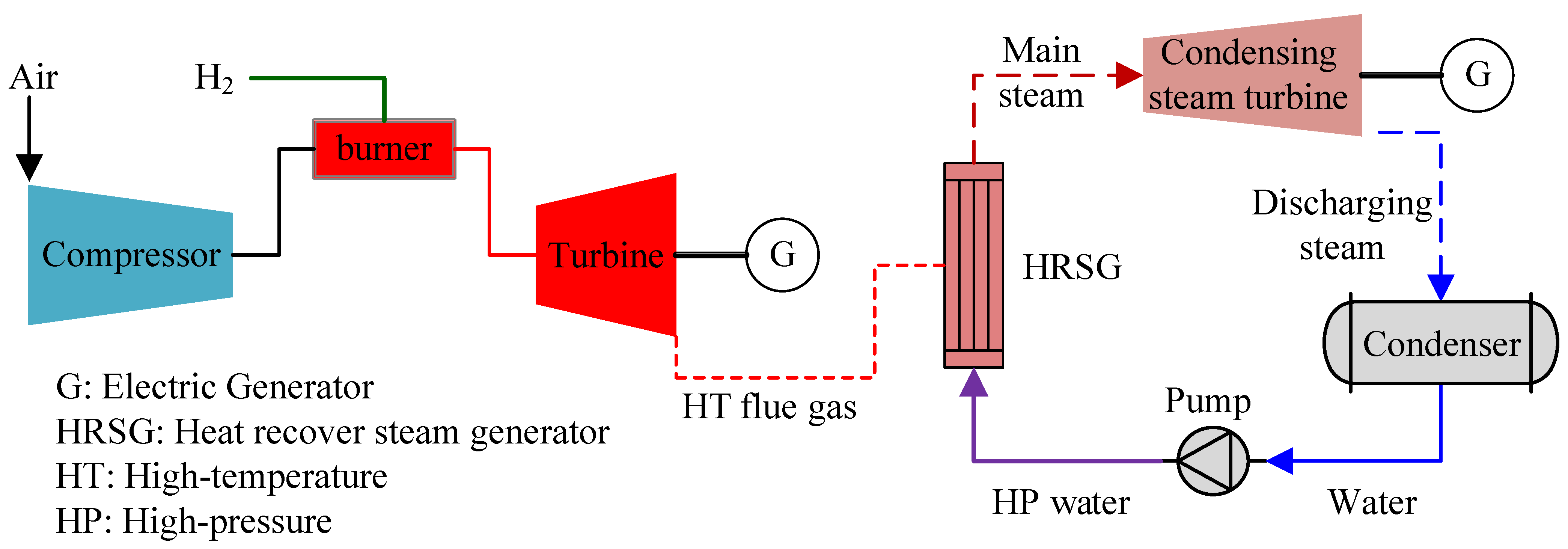
This study focuses on CCGT technology since it is ready and capable of generating medium- and large-scale power. The typical process flow diagram of hydrogen-fueled CCGT is shown in Figure 2. Note that only power, rather than power and heat, is considered as the final product in this study, so the condensing steam turbine is integrated. It is assumed that every plant consists of two sets of CCGTs and the efficiencies of these plants with pure hydrogen as fuel could be kept same as those with natural gas. The thermodynamic performances are listed in Table 3. They are the references of state-of-art F-class and H-class CCGTs supplied by GE and Siemens. The net CCGT efficiency (ηCCGT) refers to the amount of output power produced relative to the rate of energy consumption of the fuel used. The ηCCGT in Table 3 is based on lower heating value. At present, the ηCCGT of medium-scale plant (6F.03) is 55% or higher, while that of large scale has already achieved 63.7%, which is comparable to that of hydrogen fuel cell.
The use of hydrogen and hydrogen-rich gases as a fuel for industrial applications and power generation combined with the control of polluted emissions, especially NOx, is a major key driver in the design of future gas turbine combustors. With respect to current natural gas combined cycle plants, NOx emissions limit in California for 10 MW and higher stationary gas-fired gas turbines is 9 ppm at 15% O2 and 24 ppm in Europe [26]. In China, the national limit of NOx emissions is 50 ppm; however, the regional NOx emission limit has been set to 30 ppm for all CCGT plants in several provinces, and the limit of 9 ppm has been implemented for the most advanced H-class CCGT plants.
Regarding hydrogen-fueled gas turbines, a small increase in the higher range of temperature results in an exponential increase in NOx production. High NOx emissions were reported in 85–90% of hydrogen-fueled GE 6FA test combustors [26]. However, Funke et al. performed an experimental analysis of the momentum flux ratio’s impact on flame anchoring and on the resultant formation of NOx emissions, and results showed that the dry NOx emissions at 15% O2 did not exceed 25 ppm and could be as low as 1 ppm [27]. Cappelletti and Martelli designed a pure hydrogen-fueled gas turbine burner prototype and performed experimental and numerical studies on NOx emissions, flashback limit, and burner pressure drop. In all cases, the NOx emissions were quite low, from 5 up to 38 ppm at 15% O2 [9]. Thus, the NOx emission concentration of flue gas is studied as a key variable for the life cycle of NOx emissions. This study does not focus on the NOx formation mechanism and exact amount of NOx emissions at a specific condition of a hydrogen-fueled gas turbine. Instead, the concentrations of 5, 9, 30 (baseline value), and 50 ppm are assumed in the following assessment, referring to the values obtained from the previous tests or as set by different regional regulations.
Subsequently, the flow rate of air or flue gas is the key parameter for estimating the amount of NOx emissions. Generally, most of the air feed for a gas turbine is compressed and used for combustion, for which the temperature at the outlet of the compressor may vary from 270 to 400 °C [28,29]. In a modern gas turbine, a proportion of the inlet air of the compressor is bled off to perform cooling and sealing of hot-section components. Cooling air flows are necessary to function; however, too much cooling air has a negative impact on the performance and output of a gas turbine. It was reported that the proportion of air for cooling combustors and blades accounts for 2–12% [30]. The flow rate of air feed for combustion is closely linked to the excess air coefficient. Aiming to maintain the adiabatic flame temperature in the combustor between 1300 °C and 1550 °C, the excess air coefficient (ratio of the amount of combustion air to the amount of stoichiometric air) is estimated to be 2.25–2.75 for the compressor outlet temperature in the range of 300–400 °C based on the mass and energy balance equations of the adiabatic combustion of hydrogen. Assuming that 12% of the inlet air is used for cooling in order to maximize the flow rate of final flue gas as well as the amount of NOx emissions at a given concentration, the excess air coefficient (ratio of the amount of inlet air of compressor to the amount of stoichiometric air) for the final exhaust flue gas at the turbine outlet ranges from 2.557 to 3.125. Subsequently, the flue-gas-to-hydrogen mole ratio is calculated to be 5.602, 6.280, and 6.958 for the excess air coefficients of 2.557, 2.841, and 3.125, respectively, which are used in the following assessment.

2.6. Calculation of Life Cycle of GHG and NOx Emissions

Based on the above model, the life cycles of GHG and NOx emissions of 1 kWh regenerated power (RP) are calculated as follows:
GHG = k P P · N P P , G H P + k P P · N P P , H S T + k S T · N S T + k C M · N C M N R P
NO x = j P P · N P P , G H P + j P P · N P P , H S T + j S T · N S T + j C M · N C M + j F G · N F G N R P
where kPP, kST, and kCM are the GHG emission factors of primary power (gCO2/kWh), steel (g/kg) and cement (g/kg), respectively. jPP, jST, jCM, and jFG are the NOx emission factors of primary power (g/kWh), steel (g/kg), cement (g/kg), and flue gas (g/m3), respectively. NPP,GHP and NPP,HST are the total amounts of primary power (PP) consumed in GHP and HST stages through the life cycle of the project, respectively, in kWh. NST and NCM are the amounts of steel and cement used in the project, respectively, in kg. NFG and NRP are the total amounts of flue gas (m3) and regenerated power (kWh) over the entire life cycle, respectively.

2.7. Sensitivity Analysis

The sensitivity coefficient (SC) is calculated as shown below:
SC = Δ I / I Δ F / F
where I and F are the indicator and variable, respectively, and Δ denotes the change in I or F.

3. Results and Discussion

3.1. Renewable Power Sources

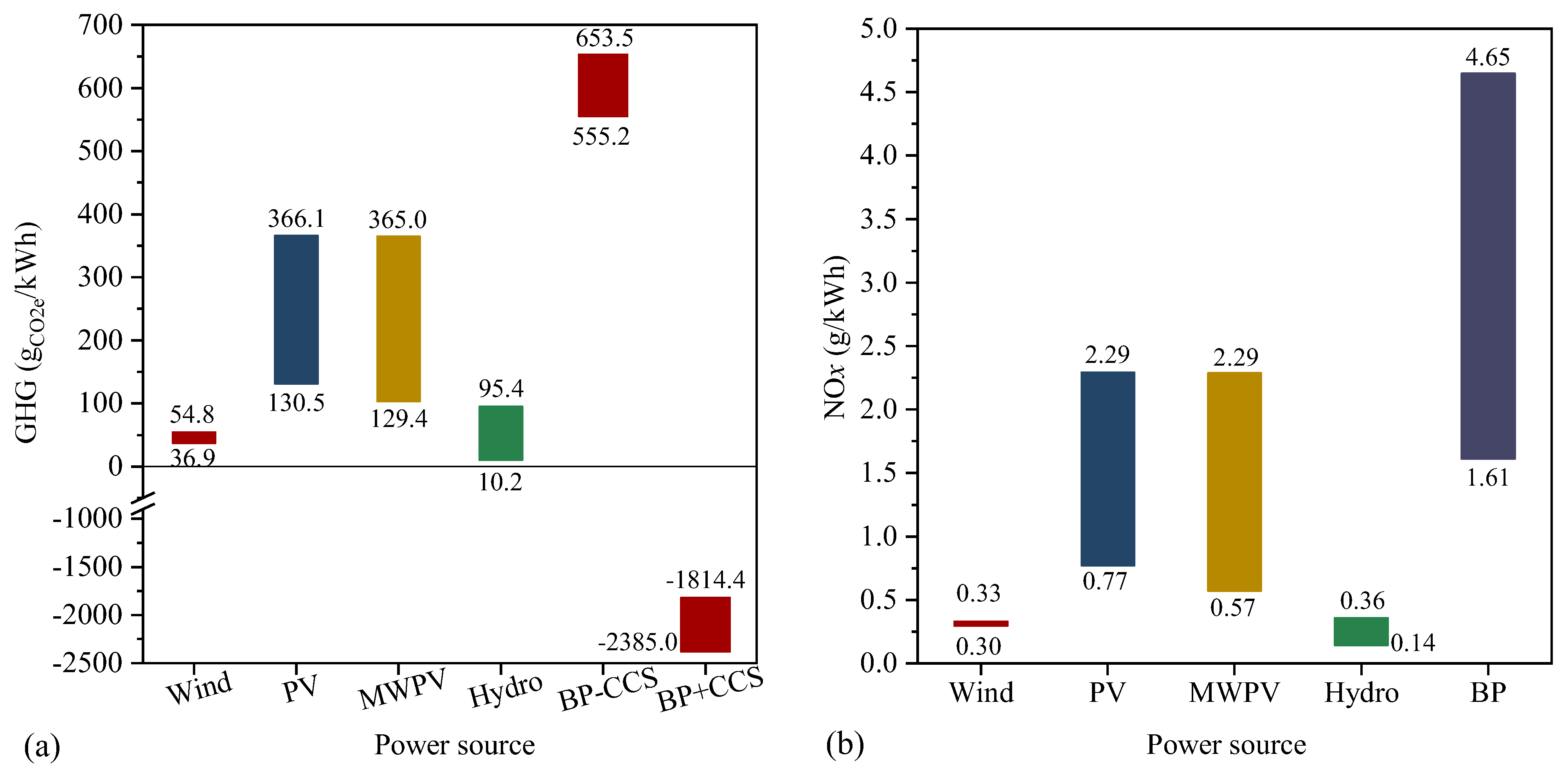
Figure 3 shows the GHG and NOx emissions with different hydrogen sources when the system is operated with the following conditions: ηWE of 80%, ηCCGT of 55.4%, NOx emission concentration of 30 mg/m3, and equivalent operating hours (EOH) of 4000 h. A 50/50 mix of wind and PV power (MWPV) is also considered in this section since the generating capacities of wind and PV power are similar in China at present.

3.1.1. GHG Emissions

As shown in Figure 3a, due to the cumulative effect, the life cycle of the GHG emissions ranges from −2385.0 gCO2e/kWh to 653.5 gCO2e/kWh. However, if biomass power is excluded and only hydro, PV, and wind power are considered, it varies from 10.2 to 366.1 gCO2e/kWh. In decreasing order of GHG emissions (mean values), the power sources are: BP-CCS > PV ≈ MWPV > hydro ≈ wind > BP + CCS.
The GHG emissions of coal power in China vary from 776 to 839 gCO2e/kWh [31,32,33,34] while those of gas power range from 373 to 561 gCO2e/kWh [32,35]. The power regenerated by PHP + CCGT technology, except for in the case of biomass power without CCS, always has significant advantages over coal and gas power in terms of GHG emissions. However, the results also indicate that PV power is not recommended to be stored by PHP technology, because its life cycle decarbonization potential is quite weak. Instead, wind and hydro power are preferable to be stored by PHP technology. Biomass power without CCS should not be used in PHP technology. Nevertheless, when CO2 capture is applied in biomass power generation, the GHG emissions are negative (from −2385.0 to –1814.4 gCO2e/kWh), and this seems to be the only way to achieve negative GHG emissions, which is in agreement with Withey et al.’s perspective [36]. Based on the difference between the life cycle of GHG emissions in Figure 3a, it can be inferred that biomass with CCS has a great potential to achieve negative GHG emissions for PHP technology, and should be paid attention to in the future. In other words, the reasonable integration of biomass utilization can radically negate the GHG emissions of non-carbonaceous renewable power, i.e., hydro, wind, and PV power, etc.

3.1.2. NOx Emissions

Figure 3b shows that the life cycle of NOx emissions generally ranges from 0.14 g/kWh to 2.73 g/kWh. In decreasing order of the NOx emissions, the hydrogen sources are: biomass > PV ≈ MPVW > wind > hydro. The NOx emissions of coal and gas power in China approximately range from 0.32 to 2.94 g/kWh (50 mg/m3 @ 6% O2) [31,33,34] and 0.33 to 0.60 g/kWh (50 mg/m3 @ 15% O2) [33,35]. The results indicate again that biomass power should not be stored by PHP technology, followed by PV and MWPV power. The NOx emissions of power regenerated by wind and hydro-based hydrogen are comparable to or less than those of fossil fuel power. Additionally, biomass has a disadvantage in terms of the life cycle of NOx emissions, although it has a significant advantage in GHG emissions when CCS is applied. Future efforts should be made to strictly restrain NOx generation during biomass power generation. Song et al. proposed the biomass and power-to-X pathway and the electricity-driven biomass conversion technologies [37], which may be applied to store renewable power and simultaneously achieve negative GHG emissions and lower NOx emissions [38].
The share of biomass power in many regions is very small and the demand for biomass power storage is weak. More importantly, the storage of biomass is often necessary due to its seasonal production versus the need to produce energy all year round. Compared with solar and wind, it is relatively easy to store biomass at the production site, intermediate site, or plant, which is one of the unique advantages of biomass. Taken together, it is necessary to apply CCS to biomass power generation if it is stored by PHP technology; otherwise, biomass power should not be included in the scope of PHP+CCGT technology.

3.1.3. Contributions of Different Stages

Table 4 illustrates the shares of GHG emissions in different stages. For all renewable power sources except biomass power with CCS, the GHP stage has the largest GHG emissions, which contribute 83.7–99.1% of the total emissions; meanwhile, the HST and PCD stages contribution little, indicating that the GHP stage is the key to further reducing the life cycle of GHG emissions with PHP + CCGT technology.
Table 5 illustrates the shares of NOx emissions in different stages. For all renewable power sources, the GHP stage generally has the largest NOx emissions, which contributes 37.1–96.4% of the total emissions. The PRG stage contributes the second largest (1.8–61.3%), indicating that the GHP stage is also the key to further reducing the life cycle of NOx emissions with PHP technology. Based on the above analyses and considering the distributions of renewable resources, the following analyses are conducted with a focus on wind power.

3.2. Water Electrolysis Efficiency

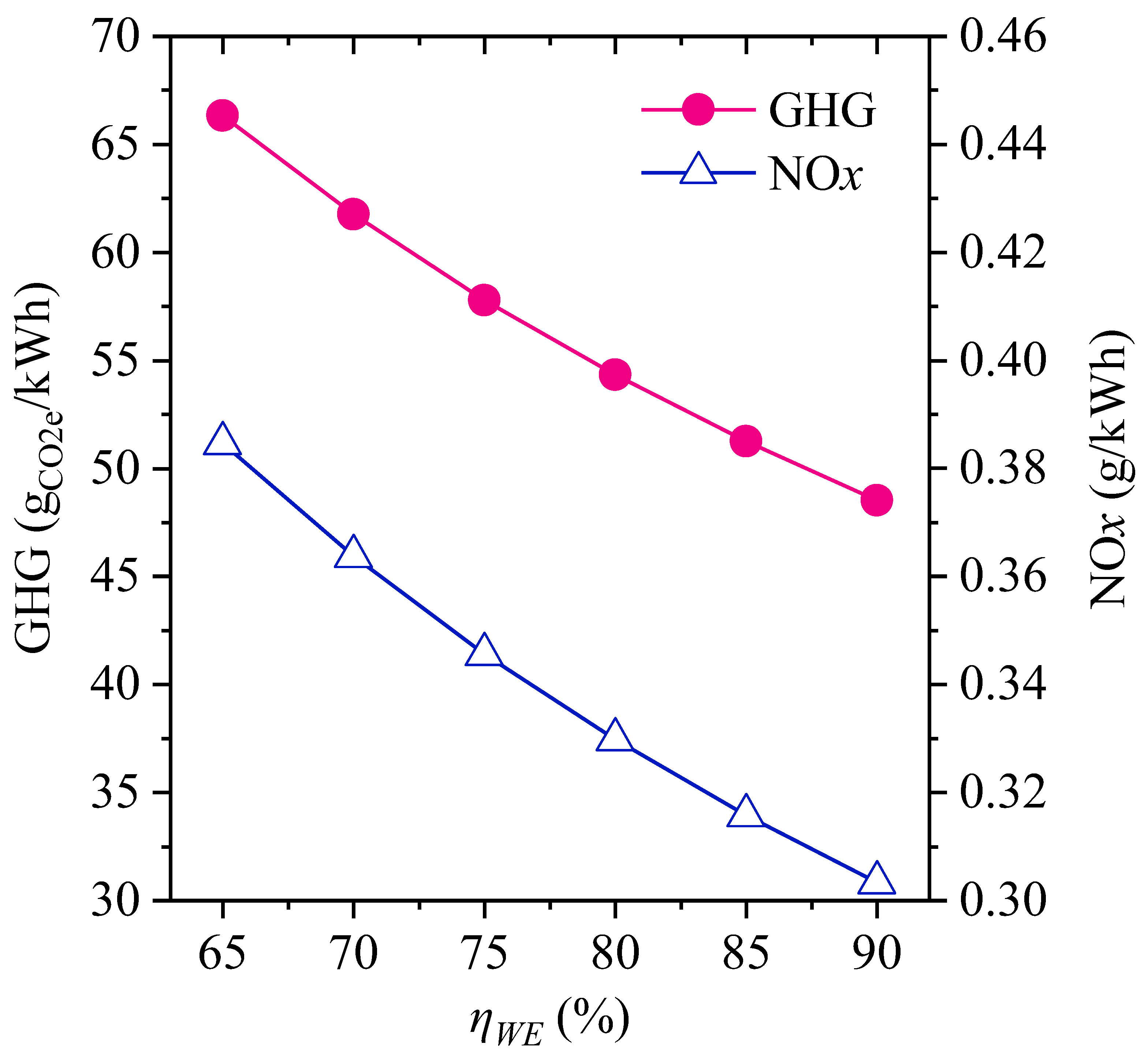
Figure 4 shows the influences of water electrolysis efficiency in the range of 65–90% for hydrogen production when the system is operated with the following conditions: a wind power ηCCGT of 55.4%, NOx emission concentration of 30 mg/m3, and EOH of 4000 h. The GHG and NOx emissions gradually decrease with the increase in ηWE, because the power consumption falls and then leads to the decreases in all emissions. The sensitivity coefficients of the life cycle of the GHG and NOx emissions to ηWE are 0.91 and 0.79, respectively, indicating ηWE is a key variable of the PHP+CCGT technology.

3.3. Influences of CCGT Operation

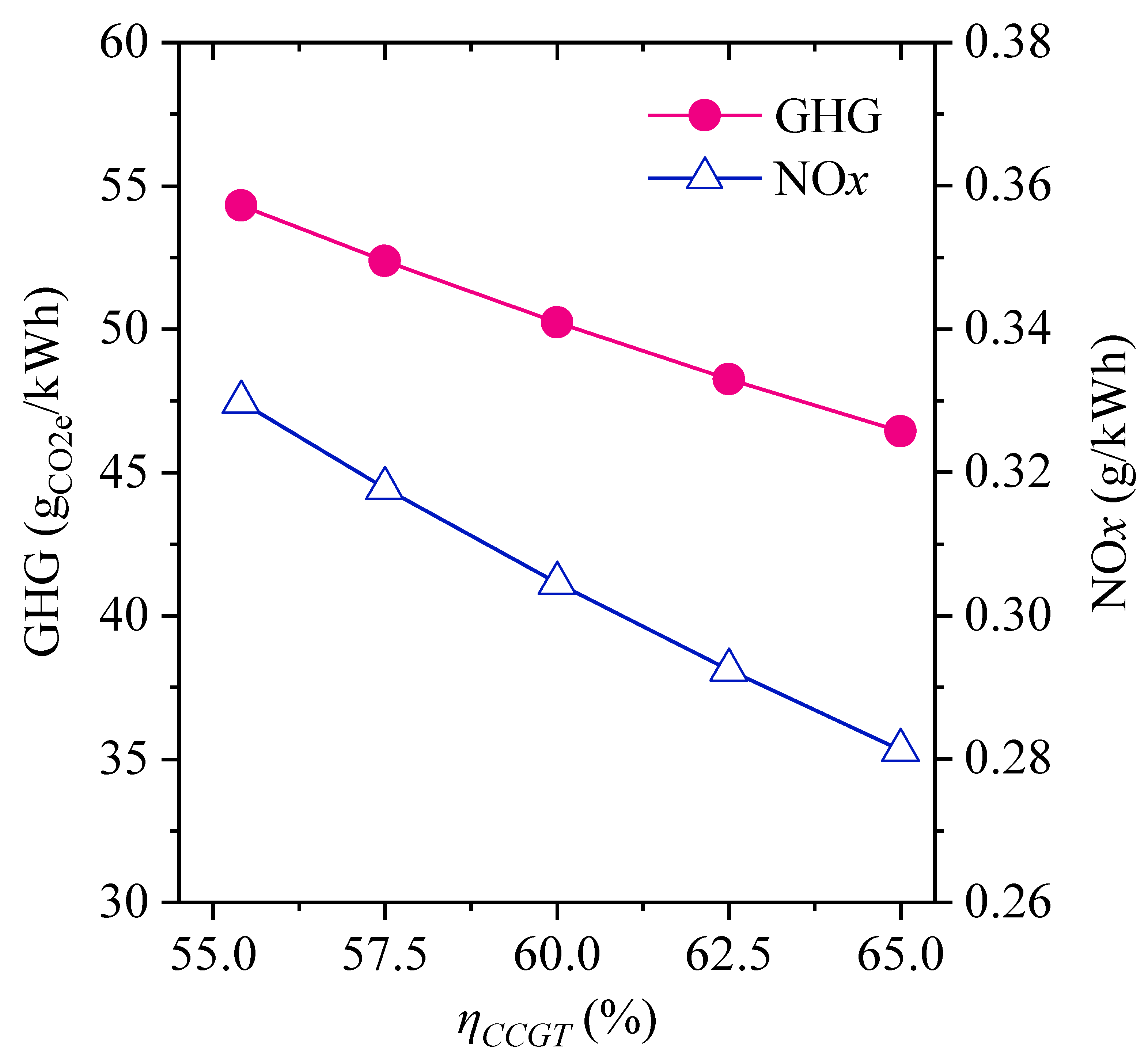
Figure 5 shows the influences of net CCGT efficiency in the range of 55.4–65% when the system is operated with the following conditions: a wind power ηWE of 80%, NOx emission concentration of 30 mg/m3, and EOH of 4000 h. With the increase in ηCCGT, the amount of regenerated power increases, then the life cycle of the GHG and NOx emissions are reduced accordingly. The sensitivity coefficients of the life cycle of GHG and NOx emissions to ηCCGT are 0.95 and 0.96, respectively, which are greater than those of ηWE. The comparison indicates that ηCCGT is a significant variable for the PHP+CCGT technology. Therefore, close attention should be paid to improving ηCCGT in the future. Efficient gas turbines should be vigorously developed, especially small- and medium-scale gas turbines, considering the decentralized model for the future of energy structures. Moreover, combined heat and power, also known as cogeneration, is a measure to substantially increase the overall efficiency of energy systems that should be investigated in the future.

3.4. EOH and NOx Concentration

When the EOH increases from 3000 h to 6000 h, the life cycle of the GHG emissions gradually decreases from 54.65 to 53.99 in gCO2e/kWh, and the life cycle of NOx emissions slightly decreases from 0.330 to 0.329 in g/kWh. The sensitivity coefficients of the life cycle of GHG and NOx emissions to EOH are on average −0.002. These indicate that EOH is not an important parameter for PHP technology. The reason is that, based on this life cycle model, only the allocation of the emissions in the PCD stage varies with EOH; however, the contributions of this stage are very small, as indicated in Table 4 and Table 5.
Under the same operating conditions, the result indicates that the life cycle of NOx emissions linearly decreases from 0.39 g/kWh to 0.26 g/kWh when the NOx emission concentration of flue gas declines from 50 mg/m3 to 5 mg/m3. The sensitivity coefficient of the life cycle of NOx emissions to the emission concentration is on average 0.14, which is between those of EOH and ηWE. The reason is that the contribution of the PRG stage does not exceed 29% (Table 5), and the GHP stage is still the major contributor.

3.5. Plant Scale

Table 6 shows the life cycle of GHG and NOx emissions at different scales. The PHP system is operated with the following conditions: a wind power ηWE of 80%, NOx emission concentration of 30 mg/m3, and EOH of 4000 h. Note that ηCCGT at different scales are not the same. With the increase in the plant scale, the life cycle of GHG and NOx emissions decreases by approximately 13%. The contribution of the PCD stage drops slightly, which is not the key reason for these reductions in emissions. The decreases in the life cycle of GHG and NOx emissions are mainly caused by the increase in ηCCGT. If the ηCCGT values are the same, the decreases are less than 0.9%. In general, the plant scale is a minor factor for PHP technology in terms of the life cycle of GHG and NOx emissions in the premise of similar ηCCGT at different plant scales.

3.6. Potential of Reduction in the Future

Based on the above results, the ranges of lthe ife cycle of GHG and NOx emissions are calculated for current and future scenarios and then compared with those of coal and gas power. In this section, only hydro, PV, and wind power are considered as the power sources for storage. The emissions of renewable power generation are kept unchanged. In the case of the current scenario, the emissions are calculated based on a ηWE of 80%, ηCCGT of 55.4%, and NOx emission concentration of 30 mg/m3. By contrast, in the case of the future scenario, the emissions are calculated based on a ηWE of 90%, ηCCGT of 65%, and NOx emission concentration of 5 mg/m3. The maximum and minimum values of the life cycles of GHG and NOx emissions are listed in Table 7. The results indicate that both the life cycles of GHG and NOx emissions will fall by at least 13%.
The power regenerated by the PHP+CCGT technology always has significant advantages over coal and gas power in terms of the life cycle of GHG emissions. Moreover, the life cycle of NOx emissions is comparable to or less than that of coal power. However, it may be greater than that of gas power when PV power is stored and used in the system. Thus, it is very urgent to reduce the GHG and NOx emissions of PV power. Although recent studies have reported lower GHG emissions for PV power, progress in NOx emissions still needs to be made [39,40].

4. Conclusions

The life cycle of the GHG and NOx emissions of regenerated power were assessed for PHP+CCGT technology. The influences of several factors were analyzed, including renewable power sources, water electrolysis efficiency, net CCGT efficiency, equivalent operating hours, NOx emission concentration, and plant scale.
When hydro and wind power are stored, PHP+CCGT technology has a significant decarbonization effect, and it is comparable to or has a small advantage in regards to the life cycle of NOx emissions. However, at present, the power regenerated by this technology wholly or partially from PV power has a small advantage over gas power in terms of GHG emissions, but does not have an advantage over coal and gas power regarding the life cycle of NOx emissions. Preference should be given to storing hydro and wind power, followed by PV power.
Storing and converting biomass power by PHP+CCGT technology shows two contradictory sides with respect to the life cycle of GHG emissions. In the case of biomass power without CCS, the regenerated power has no advantage over gas power; while in the case of biomass power with CCS, it is the only power source that can achieve a negative life cycle of GHG emissions and reveals the significance of reusing biomass. In any case, the NOx emissions of biomass power should be strictly reduced. The combination of biomass and power-to-X is a promising direction for future investigations.
Water electrolysis efficiency and net CCGT efficiency are the most important parameters that crucially affect life cycle emissions. Moreover, efforts should be made to improve these efficiencies. As cogeneration plants already have a higher conversion efficiency and are more profitable, the integration of PHP into the cogeneration model should studied in the future. This work predicts that hydrogen-fueled gas turbine has a promising and competitive prospect, and we should intensify our efforts to develop this technology.

Author Contributions

Conceptualization, G.S. and Q.Z.; Methodology, G.S. and H.Z.; Data curation, G.S.; Investigation, G.S., Q.Z. and B.S.; Formal analysis, Q.Z. and B.S.; Funding acquisition, G.S.; Resources, G.S. and Q.Z.; Software, G.S.; Validation, H.Z.; Visualization, H.Z.; Writing—original draft, G.S.; Writing—review and editing, B.S., H.Z., and H.W.; Supervision, H.W. and W.T.; Project administration, W.T. All authors have read and agreed to the published version of the manuscript.

Funding

This research was funded by the Scientific Foundation of Nanjing Institute of Technology, China (YKJ201818).

Data Availability Statement

The data presented in this study are available within this article.

Acknowledgments

The authors thank Xi Wang for his experience and collection of the construction data of the power plants.

Conflicts of Interest

The authors declare no conflict of interest.

References

  1. Statista Global Carbon Dioxide Emissions in 2020, by Sector. Available online: https://www.statista.com/statistics/276480/world-carbon-dioxide-emissions-by-sSector/ (accessed on 25 August 2022).
  2. Lamb, W.F.; Wiedmann, T.; Pongratz, J.; Andrew, R.; Crippa, M.; Olivier, J.G.J.; Wiedenhofer, D.; Mattioli, G.; Al Khourdajie, A.; House, J.; et al. A Review of Trends and Drivers of Greenhouse Gas Emissions by Sector from 1990 to 2018. Environ. Res. Lett. 2021, 16, 073005. [Google Scholar] [CrossRef]
  3. Dolci, F.; Thomas, D.; Hilliard, S.; Hancke, R.; Ito, H.; Jegoux, M.; Fu, C.; Kreeft, G.; Leaver, J.; Newborough, M.; et al. Incentives and Legal Barriers for Power-to-Hydrogen Pathways: An International Snapshot. Int. J. Hydrog. Energy 2019, 44, 11394–11401. [Google Scholar] [CrossRef]
  4. National Academies of Sciences Engineering and Medicine. Advanced Technologies for Gas Turbines; National Academies Press: Washington, DC, USA, 2020; ISBN 9780309664226. [Google Scholar]
  5. Taamallah, S.; Vogiatzaki, K.; Alzahrani, F.M.; Mokheimer, E.M.A.; Habib, M.A.; Ghoniem, A.F. Fuel Flexibility, Stability and Emissions in Premixed Hydrogen-Rich Gas Turbine Combustion: Technology, Fundamentals, and Numerical Simulations. Appl. Energy 2015, 154, 1020–1047. [Google Scholar] [CrossRef]
  6. Patel, S. First Hydrogen Burn at Long Ridge HA-Class Gas Turbine Marks Triumph for GE. Available online: https://www.powermag.com/first-hydrogen-burn-at-long-ridge-ha-class-gas-turbine-marks-triumph-for-ge/ (accessed on 20 September 2022).
  7. General Electric First GE 9HA Gas Turbines Ordered for Hydrogen-Blended Natural Gas Fueled Power Plant in China, Supporting China’s Decarbonization Roadmap. Available online: https://www.ge.com/news/press-releases/first-ge-9ha-gas-turbines-ordered-for-hydrogen-blended-natural-gas-fueled-power (accessed on 20 September 2022).
  8. Walker, S.B.; Van Lanen, D.; Mukherjee, U.; Fowler, M. Greenhouse Gas Emissions Reductions from Applications of Power-to-Gas in Power Generation. Sustain. Energy Technol. Assess. 2017, 20, 25–32. [Google Scholar] [CrossRef]
  9. Cappelletti, A.; Martelli, F. Investigation of a Pure Hydrogen Fueled Gas Turbine Burner. Int. J. Hydrog. Energy 2017, 42, 10513–10523. [Google Scholar] [CrossRef] [Green Version]
  10. Alhuyi Nazari, M.; Fahim Alavi, M.; Salem, M.; Assad, M.E.H. Utilization of Hydrogen in Gas Turbines: A Comprehensive Review. Int. J. Low-Carbon Technol. 2022, 17, 513–519. [Google Scholar] [CrossRef]
  11. Siemens Gas and Power HYFLEXPOWER: The World’s First Integrated Power-to-X-to-Power Hydrogen Gas Turbine Demonstrator. Available online: https://press.siemens.com/global/en/pressrelease/ (accessed on 20 September 2022).
  12. Rinawati, D.I.; Keeley, A.R.; Takeda, S.; Managi, S. Life-Cycle Assessment of Hydrogen Utilization in Power Generation: A Systematic Review of Technological and Methodological Choices. Front. Sustain. 2022, 3, 1–19. [Google Scholar] [CrossRef]
  13. Mehmeti, A.; Angelis-Dimakis, A.; Arampatzis, G.; McPhail, S.J.; Ulgiati, S. Life Cycle Assessment and Water Footprint of Hydrogen Production Methods: From Conventional to Emerging Technologies. Environments 2018, 5, 24. [Google Scholar] [CrossRef] [Green Version]
  14. Salkuyeh, Y.K.; Saville, B.A.; MacLean, H.L. Techno-Economic Analysis and Life Cycle Assessment of Hydrogen Production from Different Biomass Gasification Processes. Int. J. Hydrog. Energy 2018, 43, 9514–9528. [Google Scholar] [CrossRef]
  15. Therkelsen, P.; Werts, T.; McDonell, V.; Samuelsen, S. Analysis of NOx Formation in a Hydrogen-Fueled Gas Turbine Engine. J. Eng. Gas Turbines Power 2009, 131, 1–10. [Google Scholar] [CrossRef]
  16. IKE Chinese Core Life Cycle Database (CLCD). Available online: https://www.ike-global.com/#/products-2/chinese-lca-database-clcd (accessed on 16 March 2022).
  17. Zang, G.; Zhang, J.; Jia, J.; Lora, E.S.; Ratner, A. Life Cycle Assessment of Power-Generation Systems Based on Biomass Integrated Gasification Combined Cycles. Renew. Energy 2020, 149, 336–346. [Google Scholar] [CrossRef]
  18. Schmidt, O.; Gambhir, A.; Staffell, I.; Hawkes, A.; Nelson, J.; Few, S. Future Cost and Performance of Water Electrolysis: An Expert Elicitation Study. Int. J. Hydrog. Energy 2017, 42, 30470–30492. [Google Scholar] [CrossRef]
  19. Dawood, F.; Anda, M.; Shafiullah, G.M. Hydrogen Production for Energy: An Overview. Int. J. Hydrog. Energy 2020, 45, 3847–3869. [Google Scholar] [CrossRef]
  20. Bhandari, R.; Trudewind, C.A.; Zapp, P. Life Cycle Assessment of Hydrogen Production via Electrolysis—A Review. J. Clean. Prod. 2014, 85, 151–163. [Google Scholar] [CrossRef]
  21. Susmozas, A.; Iribarren, D.; Zapp, P.; Linβen, J.; Dufour, J. Life-Cycle Performance of Hydrogen Production via Indirect Biomass Gasification with CO2 Capture. Int. J. Hydrog. Energy 2016, 41, 19484–19491. [Google Scholar] [CrossRef]
  22. Wang, M.; Wang, G.; Sun, Z.; Zhang, Y.; Xu, D. Review of Renewable Energy-Based Hydrogen Production Processes for Sustainable Energy Innovation. Glob. Energy Interconnect. 2019, 2, 436–443. [Google Scholar] [CrossRef]
  23. Gardiner, M. Energy Requirements for Hydrogen Gas Compression and Liquefaction as Related to Vehicle Storage Needs. Available online: https://www.hydrogen.energy.gov/pdfs/9013_energy_requirements_for_hydrogen_gas_compression.pdf/ (accessed on 24 March 2022).
  24. Gao, C.; Chen, S.; Chen, S.; Wang, S. Life Cycle Assessment of Integrated Iron and Steel Works in China. J. Harbin Inst. Technol. 2016, 48, 177–181. (In Chinese) [Google Scholar] [CrossRef]
  25. Cui, S.; Li, Y.; Li, C.; Wang, Y. Research and Application of Life Cycle Assessment in Cement Industry. Mater. China 2016, 35, 761–768. (In Chinese) [Google Scholar] [CrossRef]
  26. Ditaranto, M.; Heggset, T.; Berstad, D. Concept of Hydrogen Fired Gas Turbine Cycle with Exhaust Gas Recirculation: Assessment of Process Performance. Energy 2020, 192, 116646. [Google Scholar] [CrossRef]
  27. Funke, H.H.W.; Boerner, S.; Keinz, J.; Kusterer, K.; Kroniger, D.; Kitajima, J.; Kazari, M.; Horikawa, A. Numerical and Experimental Characterization of Low NOX Micromix Combustion Principle for Industrial Hydrogen Gas Turbine Applications. Proc. ASME Turbo Expo 2012, 2, 1069–1079. [Google Scholar] [CrossRef]
  28. Farzaneh-Gord, M.; Deymi-Dashtebayaz, M. A New Approach for Enhancing Performance of a Gas Turbine (Case Study: Khangiran Refinery). Appl. Energy 2009, 86, 2750–2759. [Google Scholar] [CrossRef]
  29. Park, Y.; Choi, M.; Kim, K.; Li, X.; Jung, C.; Na, S.; Choi, G. Prediction of Operating Characteristics for Industrial Gas Turbine Combustor Using an Optimized Artificial Neural Network. Energy 2020, 213, 118769. [Google Scholar] [CrossRef]
  30. Yao, X. Gas Turbine and Combined Cycle, 2nd ed.; China Electric Power Press: Beijing, China, 2017. [Google Scholar]
  31. Wang, Y.; Zhou, S.; Yao, Z.; Ou, X. Life Cycle Modeling Analysis of the Interaction Between Carbon Dioxide and Air Pollutant Emissions of Coal Power in China. Electr. Power 2021, 54, 128–135. (In Chinese) [Google Scholar]
  32. Liu, G. Analysis and Suggestion of Carbon Emission in Thermal Power Plants under the Background of Carbon Peak and Carbon Neutrality. Available online: https://kns.cnki.net/kcms/detail/11.3676.TD.20211209.0713.012.html/ (accessed on 14 October 2022).
  33. Wang, Y.; Zhou, S.; Wang, Y.; Qin, X.; Chen, F.; Ou, X. Comprehensive Assessment of the Environmental Impact of China’s Unclear and Other Power Generation Technologies. J. Tsinghua Univ. (Science Technol.) 2021, 61, 377–384. (In Chinese) [Google Scholar]
  34. Li, H.; Jiang, H.-D.; Dong, K.-Y.; Wei, Y.-M.; Liao, H. A Comparative Analysis of the Life Cycle Environmental Emissions from Wind and Coal Power: Evidence from China. J. Clean. Prod. 2020, 248, 119192. [Google Scholar] [CrossRef]
  35. Song, G.; Tang, L.; Jiang, W.; Xiao, J. Life-Cycle Environmental Impact Assessment of a Typical 2 × 200 MW Natural Gas Combined Cycle-Combined Heat and Power Plant. Electr. Power 2014, 47, 149–155. (In Chinese) [Google Scholar]
  36. Withey, P.; Johnston, C.; Guo, J. Quantifying the Global Warming Potential of Carbon Dioxide Emissions from Bioenergy with Carbon Capture and Storage. Renew. Sustain. Energy Rev. 2019, 115, 109408. [Google Scholar] [CrossRef]
  37. Song, G.; Xiao, J.; Yan, C.; Gu, H.; Zhao, H. Quality of Gaseous Biofuels: Statistical Assessment and Guidance on Production Technologies. Renew. Sustain. Energy Rev. 2022, 169, 112959. [Google Scholar] [CrossRef]
  38. Song, G.; Zhao, S.; Wang, X.; Cui, X.; Wang, H.; Xiao, J. An Efficient Biomass and Renewable Power-to-Gas Process Integrating Electrical Heating Gasification. Case Stud. Therm. Eng. 2022, 30, 101735. [Google Scholar] [CrossRef]
  39. Zhao, R.; Dong, L.; Bai, L.; Zhang, Y.; Li, X.; Qiao, Q.; Xie, M.; Wang, W. Inventoryanalysis on Carbon Emissions of Photovoltaicindustry. China Environ. Sci. 2020, 40, 2751–2757. (In Chinese) [Google Scholar] [CrossRef]
  40. Zheng, L.; Zhao, D.; Qi, X.; Chen, Y. Research on Energy Efficiency, Carbon Emission and Economy of Hydrogen Production Routes in China Based on Life Cycle Assessment Method. J. Eng. Thermophys. 2022, 43, 2306–2317. (In Chinese) [Google Scholar]
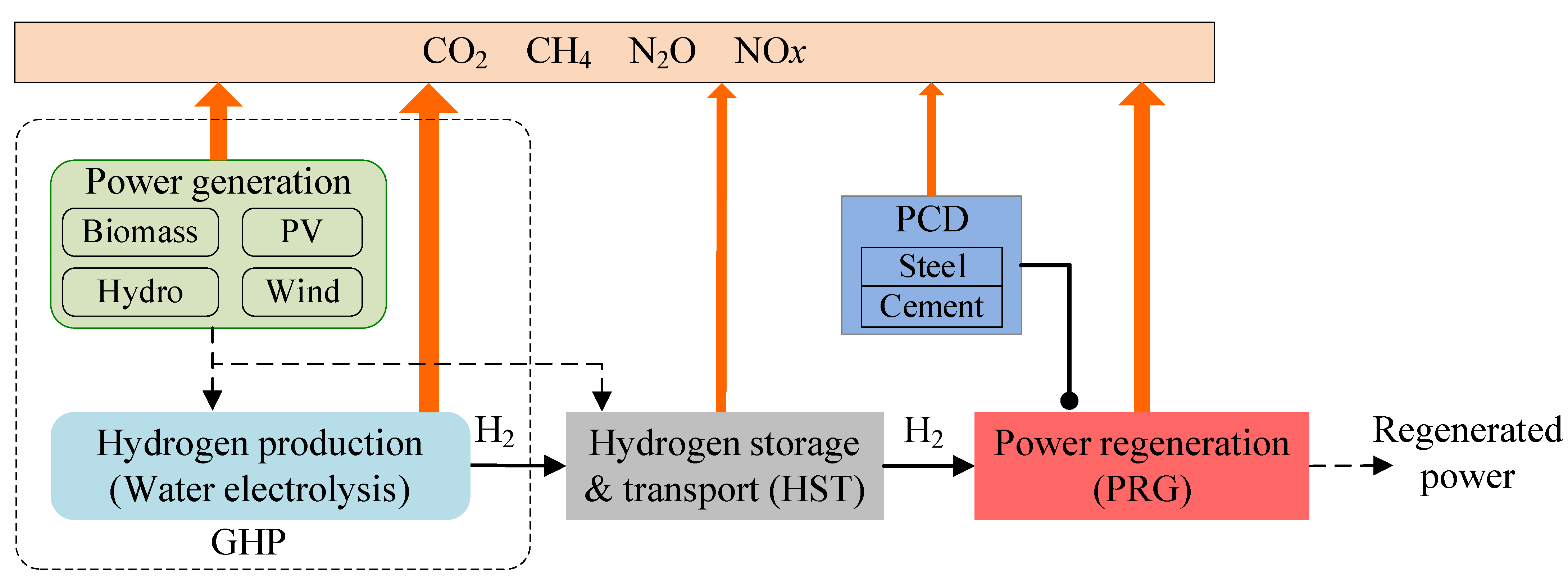
Figure 1. System boundaries and stages of the life cycle assessment of power regenerated by PHP + CCGT.
Energies 16 00977 g001
Figure 2. Process flow diagram of hydrogen-fueled CCGT.
Energies 16 00977 g002
Figure 3. Life cycle of GHG and NOx emissions with different power sources. (a) GHG; (b) NOx.
Energies 16 00977 g003
Figure 4. Variations in life cycle of GHG and NOx emissions with ηWE.
Energies 16 00977 g004
Figure 5. Variations in life cycle of GHG and NOx emissions with ηCCGT.
Energies 16 00977 g005
Table 1. GHG and NOx emissions of renewable power from different sources.
EmissionHydro PVWindBP-CCSBP+CCS
CO2 (g/kWh)3.4 50.0 17.8 203–239 −874–−665
CH4 (g/kWh)0.291 0.175 0.058
N2O (g/kWh)0.00004 0.004 0.001
NOx (g/kWh)0.021 0.265 0.089 0.56–1.670.56–1.67
Table 2. GHG and NOx emissions of green hydrogen.
TypeHydroPVWind
MaxMinMaxMinMaxMin
GHG (kgCO2e/kg H2)1.730.166.672.320.970.6
NOx (kg/kg H2)0.0050.0010.040.0120.0040.004
Table 3. Key performances of typical gas turbines and CCGT plants.
ManufacturerGESIEMENSGE
Prototype Model 6F.03SCC5-4000F9HA.01
GT power output (MW)80329448
Net plant output
CC 1 × 1 (MW)
124485680
Net plant output
CC 2 × 1 (MW)
2489701360
ηCCGT (%)55.4061.063.7
Steel (t/plant)5283672914,994
Cement (t/plant)10,29919,13739,272
Table 4. Contributions of three stages to life cycle of GHG emissions.
ShareWindPVMWPVHydroBP-CCS
GHP (%)88.0–96.095.0–98.895.8–99.183.7–94.597.5–97.6
HST (%)2.2–3.30.9–2.60.6–2.30.7–6.5~2.28
PCD (%)1.8–8.70.7–2.40.3–2.41.0–9.80.15–0.18
Table 5. Contributions of four stages to life cycle of NOx emissions.
ShareWindPVMWPVHydroBP
GHP (%)68.1–72.186.4–95.582.9–95.737.1–75.592.5–95.9
HST (%)1.7–1.90.7–2.10.5–1.90.4–0.92.16–2.24
PCD (%)0.3–1.10.05–0.40.05–0.40.3–0.70.04–1.1
PRG (%)25.9–28.93.7–11.13.7–15.023.8–61.31.8–5.3
Table 6. Life cycle of GHG and NOx emissions of CCGT plants at three scales.
Prototype ModelGE 6F.03SIEMENS
SCC5-4000F
GE 9HA.01
Net plant output (MW)2 × 1202 × 4502 × 680
ηCCGT (%)55.4061.063.7
GHG (gCO2e/kWh)54.348.847.0
NOx (g/kWh)0.330.300.29
Table 7. Life cycle of GHG and NOx emissions of PHP+CCGT technology under current and future scenarios.
ScenarioCurrentFutureCoal PowerGas Power
GHGNOxGHGNOxGHGNOxGHGNOx
Upper value366.12.29312.21.898392.945610.60
Lower value10.20.148.80.067760.323730.33
Disclaimer/Publisher’s Note: The statements, opinions and data contained in all publications are solely those of the individual author(s) and contributor(s) and not of MDPI and/or the editor(s). MDPI and/or the editor(s) disclaim responsibility for any injury to people or property resulting from any ideas, methods, instructions or products referred to in the content.