Article

A Study of Passenger Car Cabin Pre-Ventilation under the Sun

1
State Key Laboratory of Automotive Simulation and Control, Jilin University, Changchun 130025, China
2
SAIC Volkswagen Automotive Co., Ltd., Shanghai 201805, China
*
Author to whom correspondence should be addressed.
Energies 2023, 16(20), 7154; https://doi.org/10.3390/en16207154
Submission received: 24 July 2023 / Revised: 2 October 2023 / Accepted: 10 October 2023 / Published: 19 October 2023
(This article belongs to the Special Issue Recent Studies on Fluid Dynamics Applied in Energy Systems)

Abstract

:
With the increasing intelligence of automobiles, vehicle pre-ventilation can be better controlled. In summer, cars parked in the open air are directly exposed to sunlight; thus, a high-temperature environment is formed in the occupant cabin, which seriously affects the passengers and driver’s riding and driving experience. Meanwhile, lowering the temperature of the passenger compartment from a very high temperature to a comfortable temperature consumes a lot of energy. Therefore, it is increasingly important to study the pre-ventilation of the cabin in order to improve the thermal comfort of the occupant cabin and reduce energy consumption. In this paper, a new theoretical model of a cabin temperature control system is proposed. To support the theoretical model, an outdoor parking temperature rise test was carried out. Environmental parameters were obtained and used as the boundary conditions of the subsequent simulation. Based on the mechanism of the cabin temperature rise, the convective heat transfer coefficient on the body surface, the equivalent heat transfer model of the cabin, the solar radiation model and the physical properties of the air, a computational simulation of the temperature rise in the occupant cabin was carried out, and a simulation of the temperature rise in the occupant cabin exposure was studied. The simulation results were compared with the experimental findings to verify the accuracy of the simulation, which provided a reference for the design of the pre-cooling function of the occupant cabin. This study revealed that the pre-ventilation model developed reduces the vehicle cabin temperature through optimal control of air supply volumes and air supply angles. Furthermore, the developed pre-ventilation model is capable of reducing energy consumption, thereby reducing greenhouse gas emissions.

1. Introduction

The demand for automobile comfort is progressively increasing. A comfortable driving environment can not only bring good physical and mental enjoyment to people but also enable drivers to keep their attention to driving and ensure the safety of the vehicle occupants. With the development of automotive intelligence, an optimal level of thermal comfort in the vehicle cabin can be achieved prior to entering the vehicle. Thermal comfort is one of the vital factors that significantly affects the occupants’ ride comfort. Due to poor thermal comfort of the cabin, the passengers experience tiredness and even suffer from motion sickness and vomiting, which creates a profound impact on the driving and riding experience of the vehicle occupants [1,2,3]. Therefore, it is increasingly important to study the temperature rise characteristics of the occupant cabin, which is of great significance to improve the thermal comfort of the occupant cabin.
The cabin separates people from the outside environment, providing a shelter from wind and rain and a relatively closed environment. The temperature in the vehicle cabin directly affects the passengers’ feeling of riding. If the temperature is too high or too low, the thermal comfort of passengers is greatly reduced [4]. At present, the development of vehicle parking infrastructure is relatively backward, and most parking lots are open-air parking lots. During the hot summer months, the cars parked in the open air are directly exposed to intense sunlight, resulting in high temperatures in the cabin. Components in the vehicle cabin will not only undergo accelerated aging at high temperature but also release harmful substances [5,6]. Immediately after getting in the car, in order to cool it down quickly, vehicle occupants often turn on the air conditioner to high air volume and low temperature, but this will seriously affect the thermal comfort of the passengers [7]. On the one hand, due to the large heat storage capacity of the car, it is difficult to adjust the temperature in the car to the appropriate range in a short time. From the time the occupants get in the car to the time when the temperature of the vehicle cabin drops to the appropriate range, the whole human body is always in a hot state. On the other hand, due to the low air supply temperature and high flow rate, the parts of the human body blown by the cold air are significantly cooled [8]. Therefore, the human body forms a state where the whole body is hot while part of the body is cold, which seriously affects the thermal comfort of the occupants.
Through four groups of controlled experiments, Lahimer et al. found that under the condition of little difference in vehicle types, there was a large difference in the air temperature inside and outside the vehicle cabin after sun exposure, roughly within the range of 20–30 °C higher in the cabin compared to the ambient temperature [9]. In the same environment, the temperature inside a black car was about 5 °C higher than that inside a white car, which seriously threatens the lives of children or pets in the car [10]. Zhou et al. studied the temperature of the occupant cabin in outdoor parking and driving conditions in summer by means of statistical experiment and found that under driving conditions, the solar radiation of the car changes rapidly, and the surface temperature of the seat and other parts exposed to sunlight increases [11]. Suifan Chen analyzed the effects of four ventilation conditions on the driver and rear occupant. The results showed that when the vehicle is parked outdoors facing east at 14:00, the heat load of the driver and rear occupant is the lowest, and the temperature around the driver is about 52 °C. Meanwhile, roof ventilation is an effective and energy-saving cooling method for both the driver and the passenger [12]. Garrett J. Marshall et al. summarized some recent progress in electric vehicle thermal management techniques and modeling, particularly of the cabin, which includes heat load reduction, zoned and individualized cooling and automatic climate control. For heat load reduction, glass shading, surface modifications and ventilation are also mentioned with respect to the progress [13]. Libin Tan et al. used computational fluid dynamics (CFD) to investigate the internal flow field characteristics of an electric vehicle air conditioning system. The air volume distribution of the vehicle cabin was more uniform after optimization, which is more conducive to the thermal comfort in the occupant cabin [14]. C. Hariharan et al. analyzed an HVAC system in a hatchback car model using the CFD. The base heat load and temperature rise in a certain type of automobile cabin were analyzed. By implementing energy-saving measures such as different types of thermal insulation materials and blinds, their cooling effect in the cabin was studied. Various simulation results showed that the CFD simulation has advantages in studying various parameters which affect automotive HVAC energy consumption [15].
The air supply volume, air supply angle and air supply temperature have a significant effect on the temperature in the occupant cabin. Gu Zhengqi and Lu Kelong et al. adopted the method of computational fluid dynamics to improve the air volume distribution ratio of air conditioning by optimizing the guide plate in the air duct of the air conditioning system and found that the air volume distribution ratio of the supply port on the front blowing surface has a great influence on the thermal comfort of the occupant cabin [16,17]. Wang Jingyu et al. took AEQT as an evaluation index to study the influence of three factors, including air supply temperature, air supply angle and air supply speed, on the thermal comfort of the driver and co-pilot [18]. Saboora Khatoon and Man-Hoe Kim studied the human thermal comfort in the vehicle cabin by using a three-dimensional numerical analysis and an advanced thermal comfort model of vehicle cabin. The general thermal comfort index takes into account all the investigated parameters which affect the thermal comfort of a vehicle to evaluate the whole cabin environment [19]. Tobias Dehne et al. studied the thermal comfort and ventilation efficiency by comparing three vertical ventilation working conditions and ventilation mode of the instrument panel of the cabin; however, the influence of solar radiation was not taken into account [20]. Lyu Hongbin et al. studied the relationship between the temperature of the air supply port and the air at the breathing point of the occupant and found that increasing the temperature of the air supply port could improve the freshness of the air but would reduce the cooling effect of the occupant [21]. By adjusting the transverse angle of the air supply port, Somnath et al. accelerated the cooling speed in the occupant cabin on the premise of ensuring passenger comfort [22]. Tang Jiangming et al. from Hunan University optimized the horizontal and vertical angles of the air supply grille of automobile air conditioning and improved the air distribution and the thermal comfort of the occupant cabin [23]. Prakash et al. found that air supply at a fixed angle would lead to uneven temperature distribution in the occupant cabin and proposed an air supply scheme with regular changes in the air supply port angle [24].
With the development of automobile Internet technology, some models became equipped with the function of remote ventilation, which enabled people to turn on the air conditioner before getting in the car to lower the temperature in the vehicle cabin [25]. While previous research on the thermal comfort of the occupant cabin mainly focused on the manned condition and studied the influence of the air supply parameters of air conditioning on the thermal comfort of human body based on the thermal comfort evaluation index, there were relatively few or no research studies on pre-ventilation cooling under the unmanned condition. In terms of cooling purpose and flow field distribution, there is a big difference between pre-ventilation cooling and cooling for occupants’ thermal comfort. Therefore, previous research on cooling for occupants’ thermal comfort has limited reference significance in pre-ventilation cooling, and it is necessary to carry out targeted research on pre-cooling of the occupant cabin under the unmanned condition. At present, the pre-ventilation of the passenger cabin only considers rapid cooling but neglects the reduction in energy consumption. If the air supply of the air conditioner is simply turned on without adjusting and optimizing the air supply parameters of the air conditioner, the desired cooling effect will not be achieved, and the energy loss will be higher.
Therefore, a new theoretical model of cabin temperature control system is proposed in this paper to reduce the cabin temperature before using the vehicle and improve the thermal comfort of the passengers immediately after they get in the vehicle. Figure 1 shows the proposed theoretical model framework. Under the framework, in advance of several hours, the time of using the car can be entered into the control unit. The control unit automatically obtains the current time, latitude and longitude, external temperature, cabin temperature and other parameters and automatically determines the lowest energy consumption, comfortable cabin temperature, the fastest cooling curve and other parameters after the calculation. The parameter output by the control unit is inputted to the air conditioning system, which executes the corresponding instructions. At the same time, the air conditioning system feeds back the real-time monitoring cabin temperature to the control unit and realizes a synchronous adjustment of the output cooling curve to ensure that the temperature in the cabin is comfortable temperature when the car is in use.
To establish the framework illustrated in Figure 1, firstly, an outdoor parking temperature rise test was carried out, as described in Section 2. Then, the analysis of the temperature rise process in the occupant cabin was conducted. Finally, the environmental parameters obtained from the experiment were set as the boundary conditions of the computational fluid dynamics (CFD) simulation. The accuracy of the simulation results was verified by comparing the simulation results with the experimental findings of the occupant cabin temperature rise. Section 3 includes the measurement of the environmental conditions and the surface temperature of the components in the occupant cabin, combined with the knowledge of the heat transfer mechanism of the occupant cabin temperature rise stage, the introduction of the theoretical knowledge of the greenhouse effect and the provision of a theoretical basis for the subsequent simulation. The influence of the greenhouse effect at different times on the cabin temperature was studied by the CFD simulation, and the temperature field distribution of the occupant cabin during outdoor parking in the summer was determined. The influence of different air supply volumes and air supply angles on the main driving seat and air-cooling effect studies are included in Section 4. The summary of the major findings is furnished in Section 5.

2. Methodology

2.1. Occupant Cabin Temperature Rise Test Experiment Methods

The selected test vehicle was a sports utility vehicle (SUV). The test vehicle was parked in a dark room to avoid exposure to sunlight and to ensure that all parts of the car were at room temperature before the test. The outer surface of the vehicle body was cleaned to prevent dust interference with the test results. Doors and windows were closed, and the car air conditioner was switched off to internal circulation to prevent the air in the car from passing through the door and window gaps or the air-conditioning pipes during the test to produce heat exchange. Temperature sensors were placed in advance at the monitoring points requiring temperature measurement.
The equipment used in the experiment is shown in Figure 2. The voltage output range of the pyranometer (Figure 2a) varies from 0 to 1.0 V, and its current output range varies from 4 mA to 20 mA. It has a measurement range of 0 to 1800 W/m2 with a resolution of 1 W/m2 and is capable of measuring solar radiation in the wavelength range of 0.3 to 3 mm. Since 99% of the energy of solar radiation is concentrated in the short-wave region with a wavelength of 0.3 to 3 mm, the sensor can effectively monitor the intensity of solar radiation. Assuming that the test weather is clear and the solar radiation changes little in a short period of time, the collection frequency was set to 0.1 Hz in the experiment. Figure 2b shows the K-type thermocouple, which was used to measure the temperature of the parts in the occupant cabin and of the environment. Its current output range also varies from 4 mA to 20 mA. Its measurement range is −50 to 300 °C, and the measurement accuracy is ±1 °C. Figure 2c shows the GM data acquisition system, which can collect temperature data from −200 to 500 °C with an accuracy of ±0.2 °C. As the temperature of the test vehicle changes slowly, its acquisition frequency was set at 1 Hz in the test.
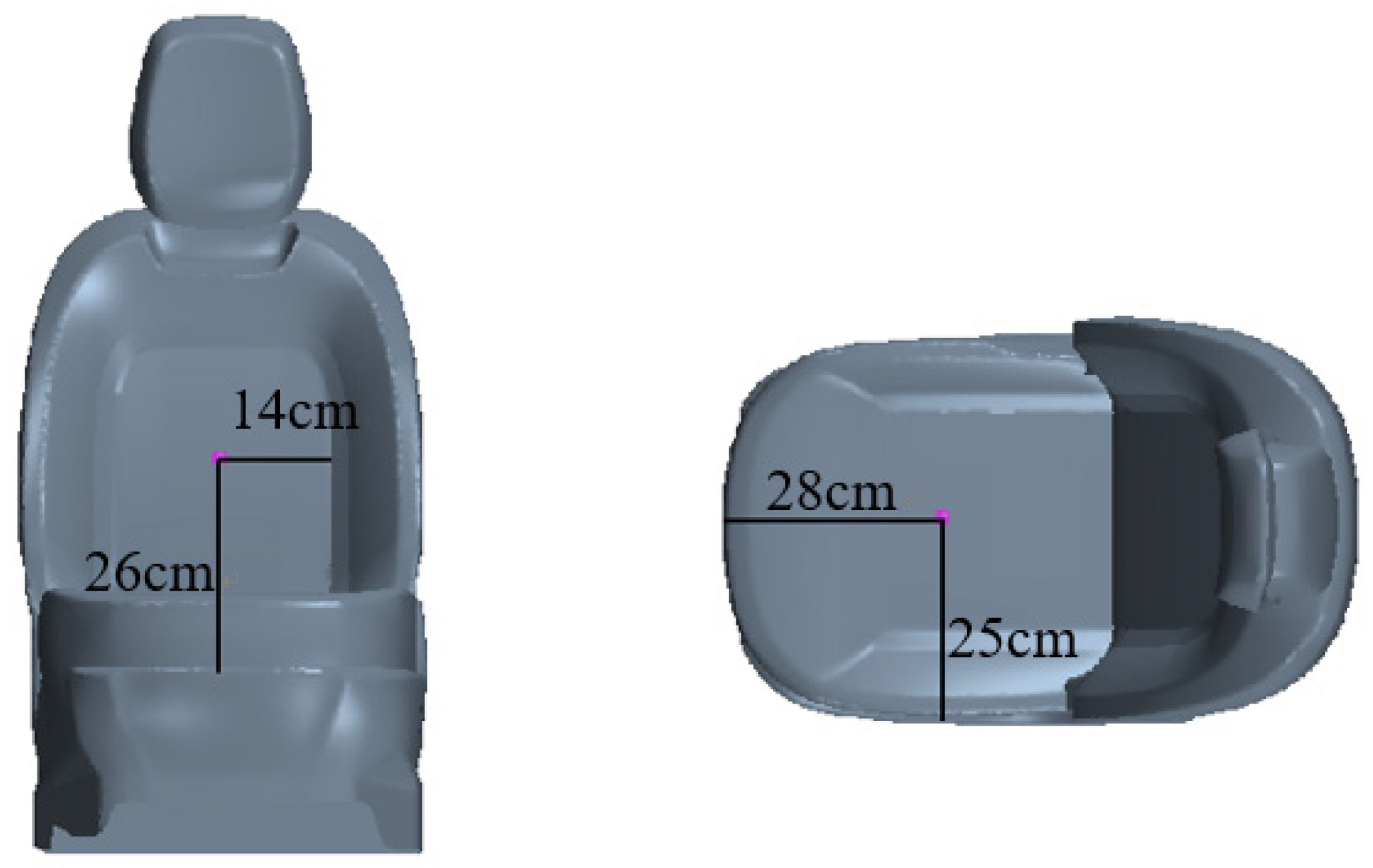
A total of 4 monitoring points were arranged in this experiment. Since the seat has the closest contact with the human body, and the temperature of the seat without cooling is very high after exposure to the sun in summer, two monitoring points are arranged on the seat, which are located in the main driver’s seat, in order to study the temperature rise on the seat. The specific positions of the driver’s seat cushion and backrest are shown in Figure 3.
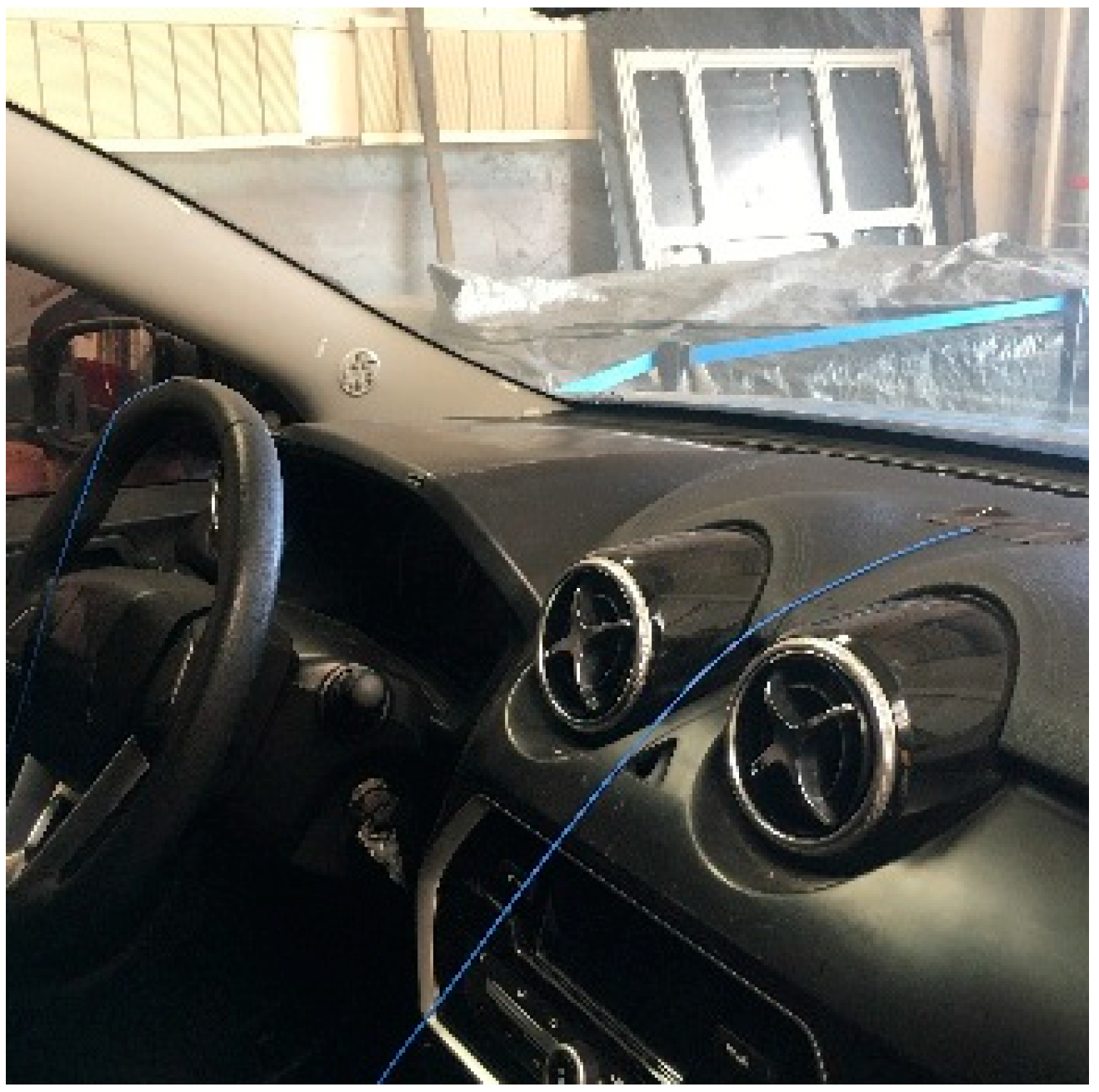
In summer, the dashboard is exposed to a wide area of the sun and its temperature is high. Therefore, a monitoring point is also arranged on the dashboard. The specific location is shown in Figure 4.
One monitoring point is arranged at the center of the rear license plate. Since sunlight can be avoided here, the ambient temperature can be accurately monitored.
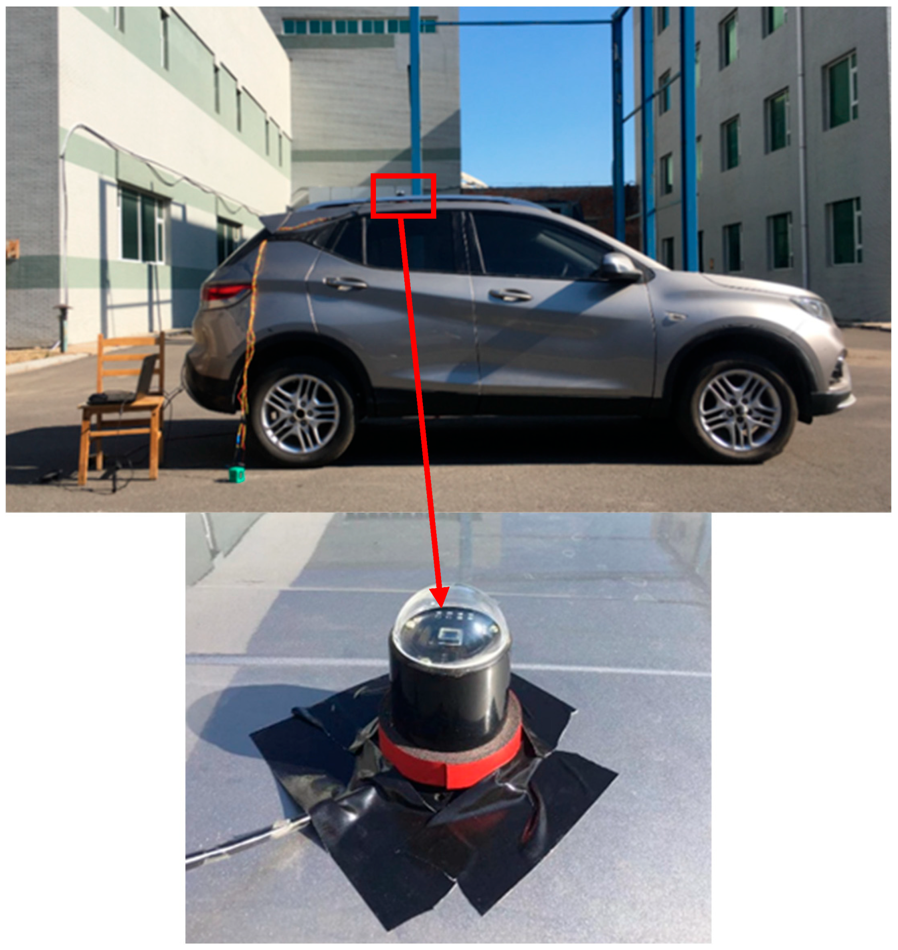
The test site is an open space outside the automobile wind tunnel of Jilin University, which can ensure that the car is not blocked by the shadow of buildings or trees and is completely exposed to the sun. The test weather is fine to ensure that the car is exposed to sufficient sunlight. The latitude and longitude of the site are latitude 43.82 degrees north and longitude 125.26 degrees east. During the test, the car was parked in the test site and the front of the car was kept facing the south, exposed to the sun. The relative position of the instrument and the test car is shown in Figure 5. The solar radiation sensor is mounted on the roof of the car and connected to the computer through a USB data cable to record the solar radiation intensity received by the car. The K-type thermocouple is attached at each monitoring point with a tape. The temperature acquisition system is placed in the trunk and connected with the K-type thermocouple to record the temperature of the parts.
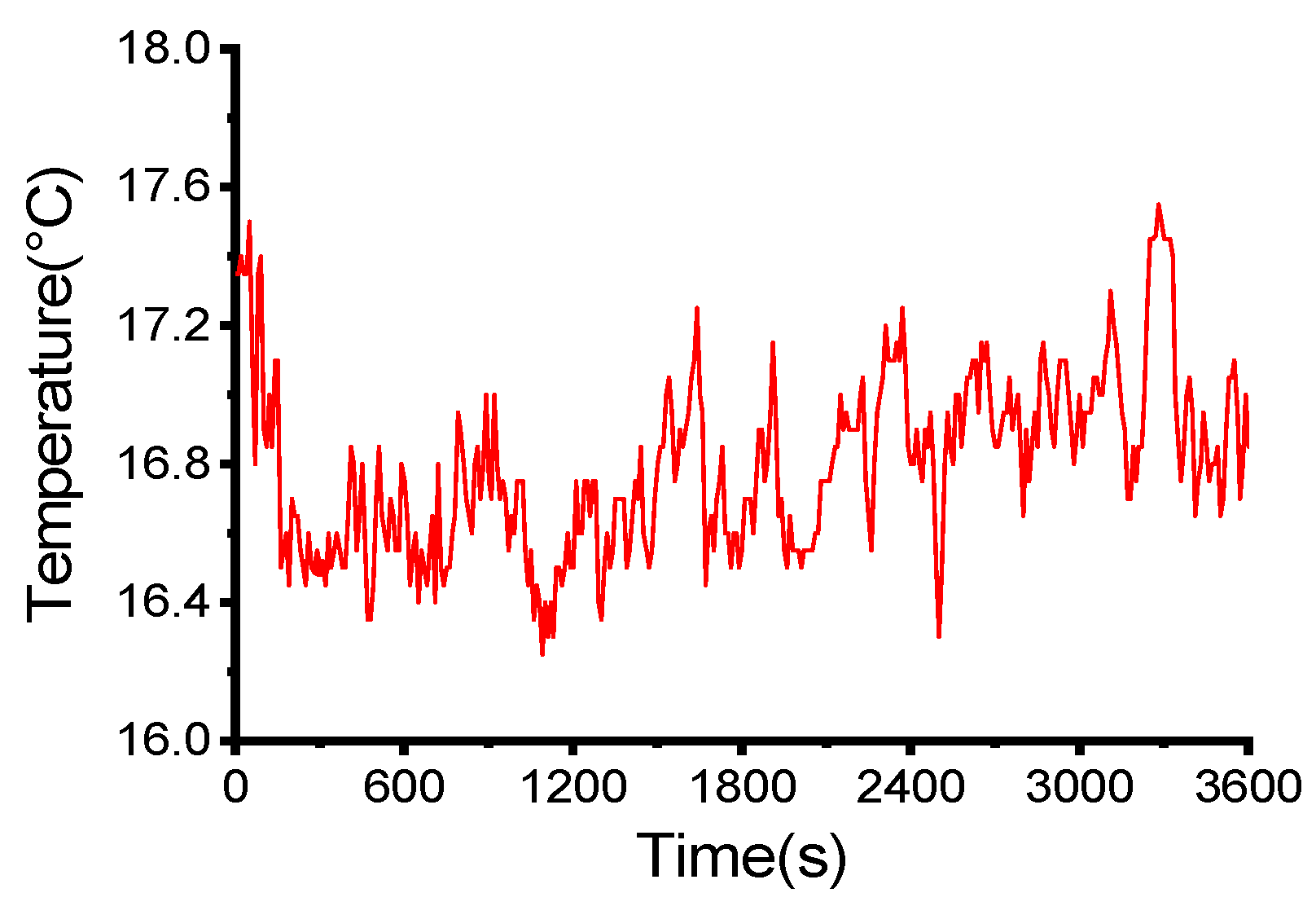
The experiment investigation was undertaken from 11:50 to 12:50 on 9 October 2020, with a total duration of 60 min. During the test, the ambient wind speed changed ranged from 1 to 3 m/s. The solar radiation intensity and ambient temperature recorded by the sensor are shown in Figure 6 and Figure 7, respectively. The solar radiation intensity fluctuates within the range of 380 to 390 W/m2, while the ambient temperature fluctuates roughly within 16.4–17.4 °C.

2.2. Analysis of Temperature Rise Process of Occupant Cabin

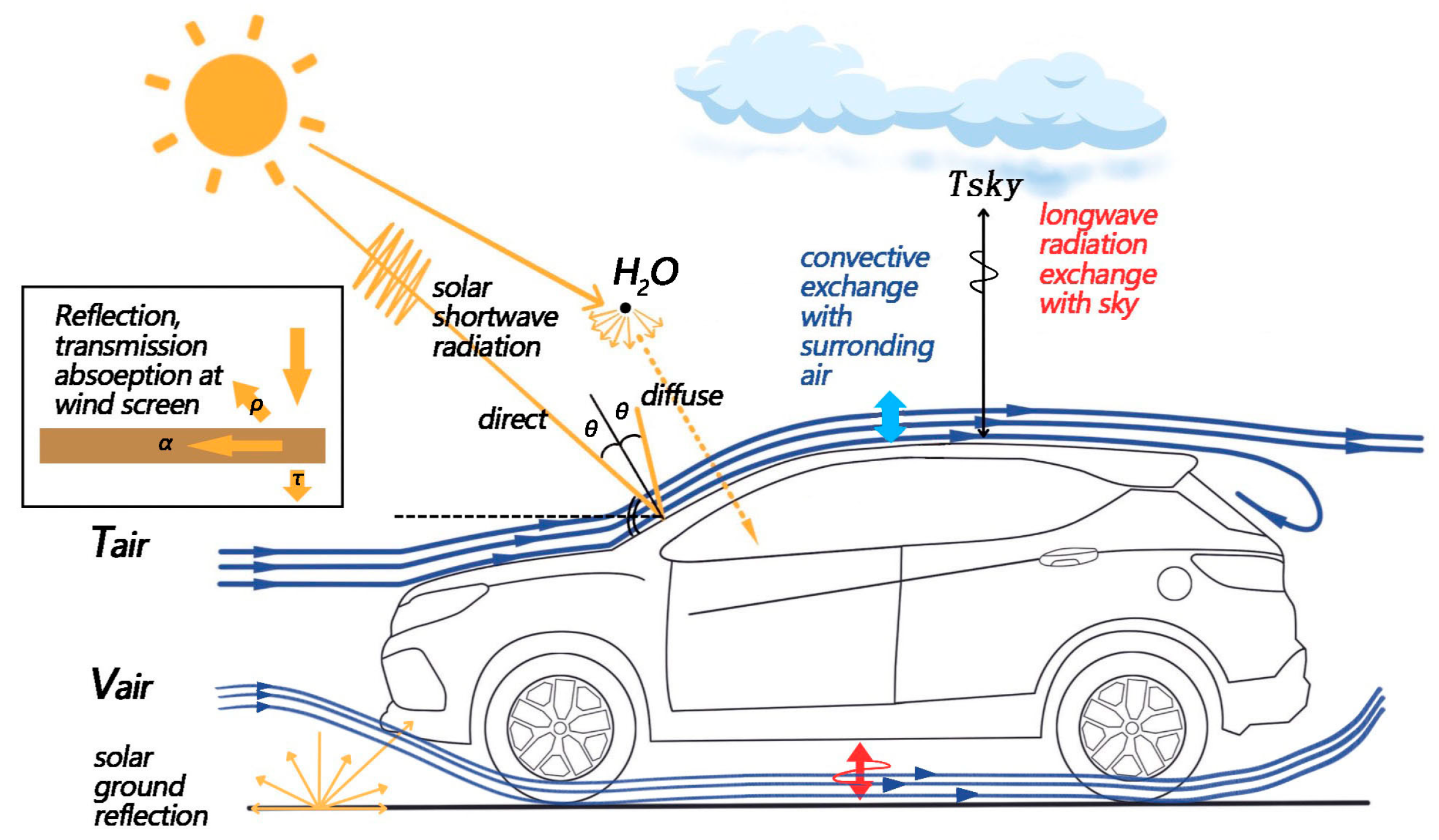
The heat exchange mode between the occupant cabin and the external environment is shown in Figure 8. Solar radiation directly irradiates the surface of the car to raise its temperature, and part of the heat on the body’ surface is transferred to the occupant cabin by the way of heat conduction. Solar radiation is transmitted through the window into the interior of the occupant cabin and absorbed by the vehicle’s interior parts, so the temperature of the occupant cabin rises. Due to the temperature difference, heat is transferred from high-temperature parts to low-temperature parts through heat conduction. Uneven temperature distribution in the occupant cabin results in a change in air density. The density of the air near the high-temperature parts decreases as it expands. The density of the air near the low-temperature parts changes very little. Under the influence of gravity, the air with high temperature and low density rises, while the air with low temperature and high density drops, forming natural convection in the cabin and generating heat exchange.
When the temperature in the occupant cabin rises to a certain value, the heat is transferred from the occupant cabin to the exterior surface of the car body through the wall, and the heat is transferred to the external environment by convection. The temperature in the occupant cabin tends to stabilize when the amount of heat absorbed by the occupant cabin equals the amount of heat emitted.
By conducting the temperature rise process of the occupant cabin, it is noted that the heat transfer modes between the vehicle and the external environment mainly include thermal convection, thermal conduction, thermal radiation and solar radiation, resulting in the temperature rise in the occupant cabin.

2.3. Simulation of the Temperature Rise of the Vehicle Cabin

2.3.1. The Setting of the Temperature Rise Model of the Occupant Cabin

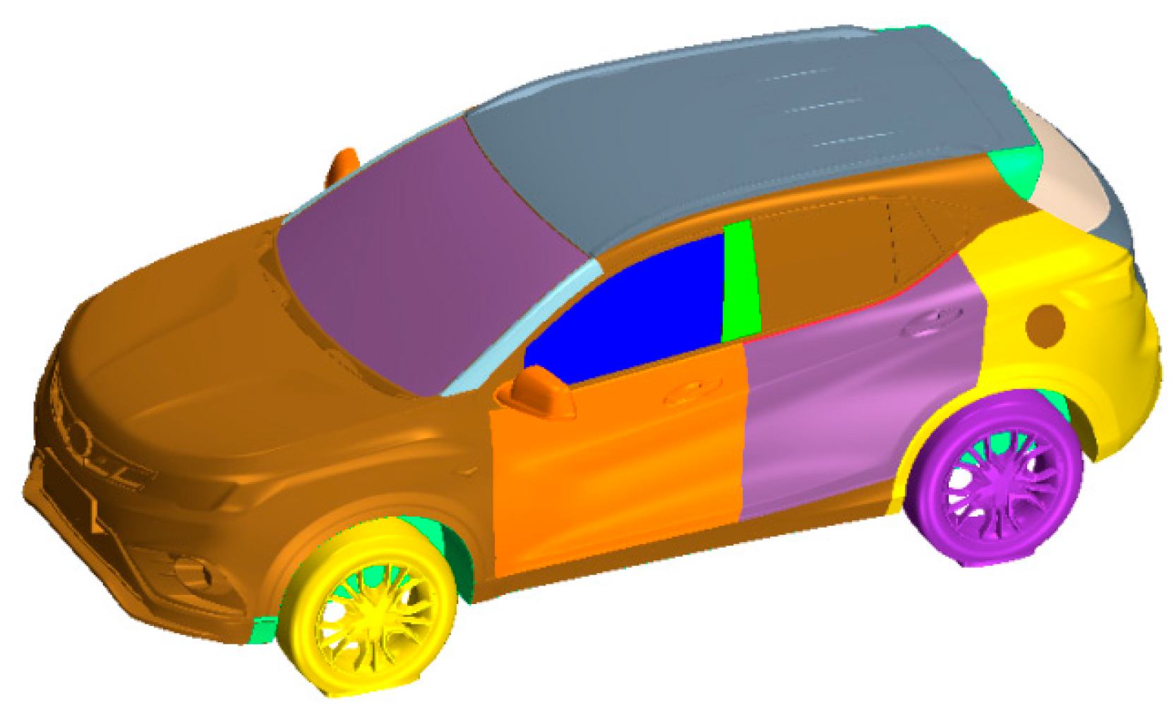
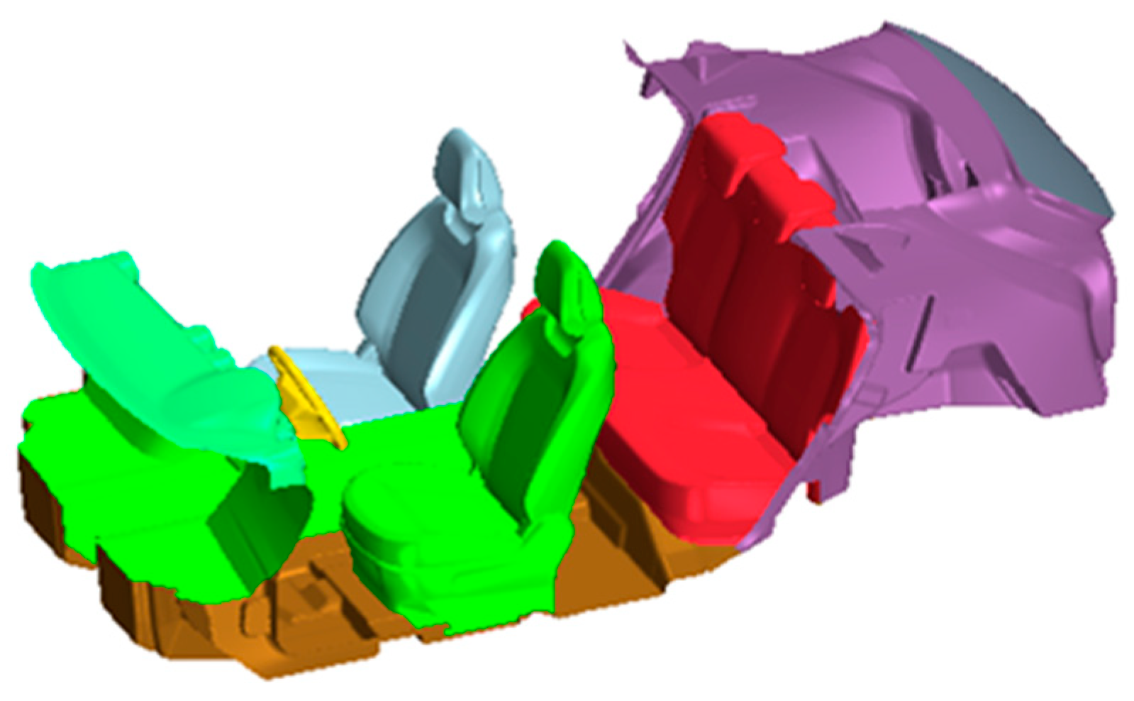
In order to analyze the effects of solar radiation, external air convection and heat transfer of the vehicle body on the temperature of the occupant cabin, the CAS (class A surface) model outside the vehicle body and the occupant cabin model are divided into areas as shown in Figure 9 and Figure 10. The outer CAS is divided into 11 areas: windscreen, rear windscreen, front window, rear window, A pillar, B pillar, front door, rear door, trunk, roof and floor. The division of car body structure corresponds to 11 regions of CAS. The interior part is divided into 6 parts: instrument panel, steering wheel, cowl panel, driver’s seat, front passenger seat and rear seat. For the exterior surface of vehicle body, a triangular surface mesh is used to divide it.
The simulation boundary conditions have a significant impact on the computational modeling results. During the temperature rise, the four air supply outlets of the air conditioner are closed, so they are treated as wall. The simulation duration is consistent with the test, the time step is set to 1 s, and the internal iteration is set to 10 steps. During the experiment, the ambient temperature fluctuates in the range of 16.4–17.2 °C, and 17 °C is taken for the simulation calculations.
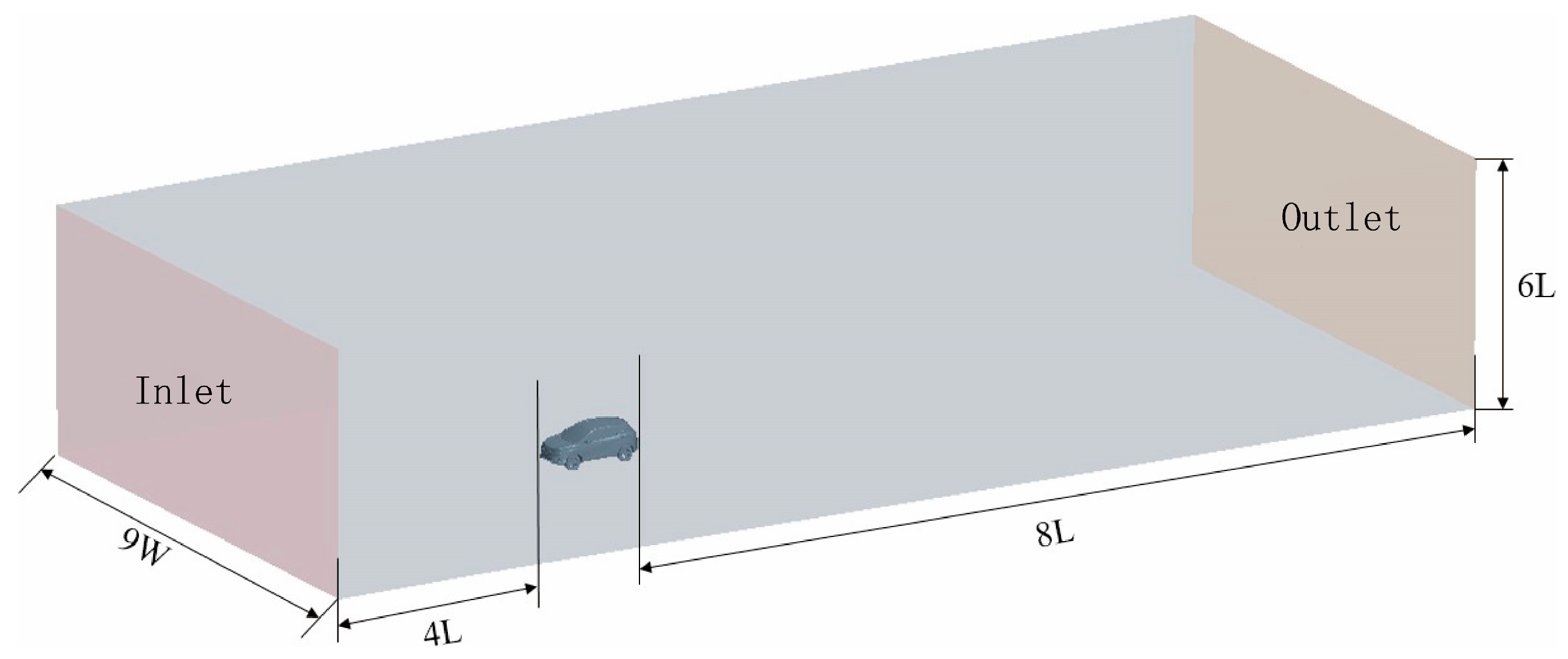
The front section of the wind tunnel calculation area established in this paper is 4 times the vehicle length, the rear section is 8 times the vehicle length, the entrance width of the calculation area is 9 times the vehicle width, and the height is 6 times the vehicle height, as shown in Figure 11. After calculation, the blockage ratio is 1%, which meets the requirements of the wind tunnel test theory. The inlet of the calculation domain is set as the speed inlet. According to the ambient wind speed tested in Section 2, the wind speed is set as 2 m/s here. Pressure outlet with outlet is set as 0 Pa. The wall boundary is set as slip boundary. The air temperature at the inlet of the calculation domain is set as 27 °C. The body wall is set as a constant temperature wall of 30 °C, and there is a temperature difference of 3 °C with the air. The walls of the calculation domain are set as adiabatic walls.
Since the fluid flow state depends on the force it receives, according to the principle of similar flow, the fluid flow state can be judged based on the dimensionless quantity. Reynolds number represents the ratio of inertial force and viscous force and is used to measure the effect of viscous force in fluid motion. When the Reynolds number is small, the viscous force is dominant. The expression of the Reynolds number is shown in Equation (1):
R e = ρ V L μ ,
According to Equation (1), the Reynolds number of the simulation model is 4.3 × 10⁵, indicating that the flow state has entered turbulence. Therefore, the physical model is selected as the turbulence model. Realizable K-epsilon turbulence model can accurately predict the velocity and temperature distribution of air flow under non-isothermal free jet and can accurately simulate the maximum velocity and temperature gradient under jet flow [26]. Therefore, the realizable K-epsilon turbulence model is selected for the simulation.
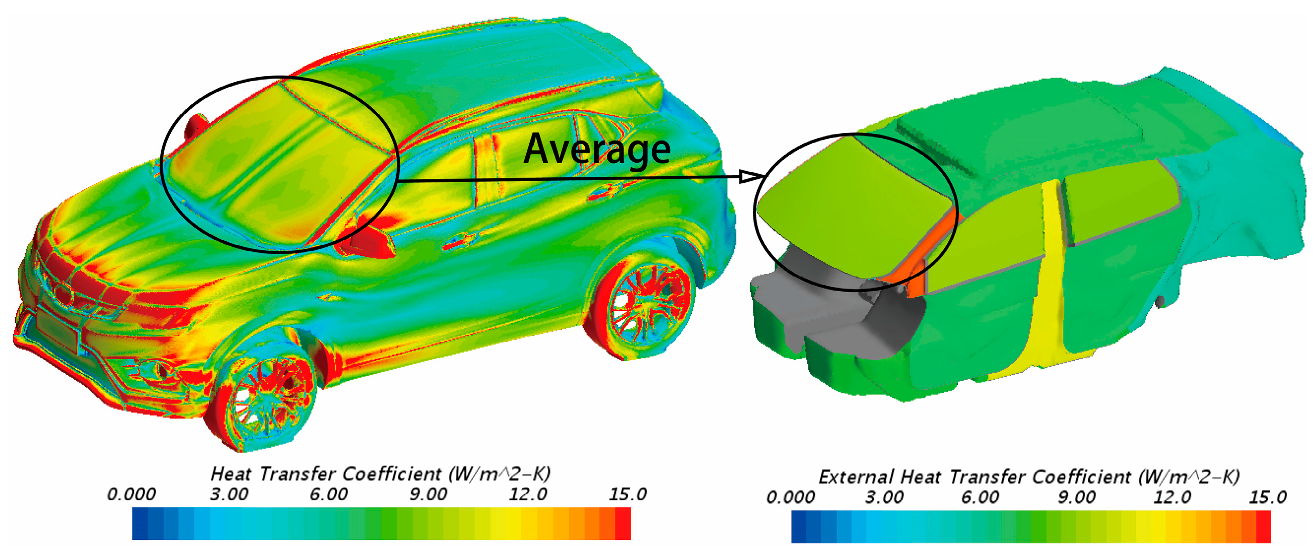
The left image in Figure 12 reflects the calculation result of the surface heat transfer coefficient. It can be seen that there is a large difference in the heat transfer coefficient between various surfaces of the body; therefore, it is unreasonable to set the body surface as a uniform h. In this paper, the heat transfer coefficient of each part of the body surface is averaged and assigned to the corresponding area of the passenger cabin. Taking the front windshield as an example, the surface heat transfer coefficient h of the front windshield was obtained by using the exterior surface of the car body. The surface mean convective heat transfer coefficient was obtained by averaging h of the front windshield using Equation (2), and then h ¯ was assigned to the front windshield area of the occupant cabin, and the rest of the occupant cabin was treated in the same way. The surface heat transfer coefficient of each part after treatment is shown on the right of Figure 12.
h ¯ = h d a A ,
The automobile body structure is complex, and its materials are numerous. Modeling every component and material accurately not only requires cleaning up complex geometry and increasing the complexity of the model but also greatly increases the computational costs. Therefore, this paper adopts the method of equivalent thermal resistance to simplify the model [27,28]. Each area of the car body is equivalent to a single material with uniform thickness, and its density, thermal conductivity and specific heat capacity are constant which do not change with temperature.

2.3.2. Establishment of Radiation Model

The radiation reaches the surface of the object and is absorbed within a very short distance. Therefore, it is believed that the radiation only occurs on the surface of the object. In STAR-CCM+, according to the effect of the medium in the solution space on radiation, it can be divided into two radiation transfer models: participating medium radiation and surface-to-surface radiation (S2S). The former needs to consider the absorption, emission and scattering of radiation by the medium in the space, while the latter regards the medium in the space as a permeable body. The air in the occupant cabin has limited absorption and scattering of solar radiation and can be regarded as a permeable body. Therefore, in this paper, surface-to-surface radiation is selected for the radiation transfer model.
The spectral absorption ratio of an object is related to the wavelength. There are two spectral models in STAR-CCM+, namely gray body thermal radiation and multi-band thermal radiation. Due to the extremely high surface temperature of the sun, it can reach 5800 K. The solar radiation emitted by it covers a wide spectrum and is distributed in the range of 0.3–100 μm. If the wavelength of solar radiation is regarded as a single band, it will not be able to simulate the greenhouse effect in the occupant cabin, making the thermal load of the occupant cabin lower than actual value. In order to make the thermal load of the occupant cabin similar to the actual situation, this paper uses a multi-band radiation model to simulate solar radiation.
The transmittance of the window glass and the optical characteristic parameter distribution of each area of the vehicle body are shown in Table 1 and Table 2. In the simulation, the radiation property of the vehicle body wall surface will be set according to them.
Since the position and intensity of solar radiation will change over time, it is necessary to simulate solar radiation under unstable conditions. Changes in parameters such as altitude, azimuth and solar radiation intensity are simulated using the SOLPOS algorithm in NREL, which can calculate the above parameters based on latitude, longitude and time. In the simulation process, set the latitude, longitude and time in the simulation according to the test location and time in Section 2.
In the natural temperature rise stage, the difference in the temperature inside the car causes the air density in different areas to change. Under the action of gravity, the air of different densities exchanges positions, forming natural convection. The Rayleigh number is the product of the Prandtl number and the Graschev number. The Rayleigh number can be used to determine whether the flow state of natural convection is laminar or turbulent. When the Rayleigh number is greater than 108, the flow state is turbulent [29].
R a = G r P r ,
where Pr is the Prandtl number (for the air temperature at 0–80 °C, the Prandtl number can be set to 0.7 [30]); Gr is the Graschev number.
According to Equation (3), the Rayleigh number Ra is roughly in the range of 3 × 10⁷ to 6 × 10⁷ in the temperature rise state of the occupant cabin, which did not reach the turbulent state and is still in the laminar flow. Table 3 shows the thermophysical properties of dry air under 1 standard atmospheric pressure [30]. The temperature difference between the air and the solid wall in the occupant cabin is within 200 °C; therefore, the Boussinesq model can be used to simulate the natural convection in the occupant cabin. In the Boussinesq model, the air density is constant. The buoyancy F received by air at different temperatures is calculated by Equation (4):
F = ρ g V β ( T r e f T ) ,
It can be seen that the higher the air temperature, the greater the buoyancy received. In the equation, ρ is the density of air, which is taken as 1.165 kg/m3 in this paper; g is the gravitational acceleration, taken as −9.81 N/kg; V is the volume of air; β is the thermal expansion coefficient of air, which is taken as 0.0036/K in this paper; Tref is the reference temperature, which is taken as 30 °C in this paper. T is the temperature of the air.
The thermal conductivity λ and dynamic viscosity μ can be calculated using the Sutherland formula:
λ = λ 0 ( T 0 + S λ T + S λ ) ( T T 0 ) 1.5 ,
μ = μ 0 ( T 0 + S μ T + S μ ) ( T T 0 ) 1.5 ,
where T0 is the reference temperature equal to 273.15 K; λ0 is the thermal conductivity of air at 1 standard atmosphere and reference temperature equal to 0.0244 W/(m·K); Sλ is the Sutherland constant of air thermal conductivity equal to 194 K; μ0 is the aerodynamic viscosity at 1 standard atmosphere and reference temperature equal to 1.72 × 10⁻⁵ kg/(m·s); and Sμ is the Sutherland constant of aerodynamic viscosity equal to 115 K. It can be seen from Table 3 that the specific heat capacity has a small change. In the simulation, the specific heat capacity is taken as a fixed value of 1.006 kJ/(kg·K).
At present, the most widely used method in engineering is the Reynolds Averaged N-S (RANS) method. The RANS method does not directly solve the instantaneous Navier–Stokes equation but solves the time-averaged momentum equation. The RANS method can not only avoid the problem of a large amount of calculation but also has achieved good results in practical engineering applications. Therefore, in the simulation process of this study, the RANS method was selected to simulate the turbulence.

2.3.3. Simulation of Outdoor Parking Temperature Rise in Autumn

Since the occupant cabin temperature rise test was carried out in autumn, this section uses the environmental parameters obtained from the test as boundary conditions to perform the numerical simulation calculations of the temperature rise process in the occupant cabin under outdoor parking conditions in autumn and uses the test data to verify the results of the simulation.
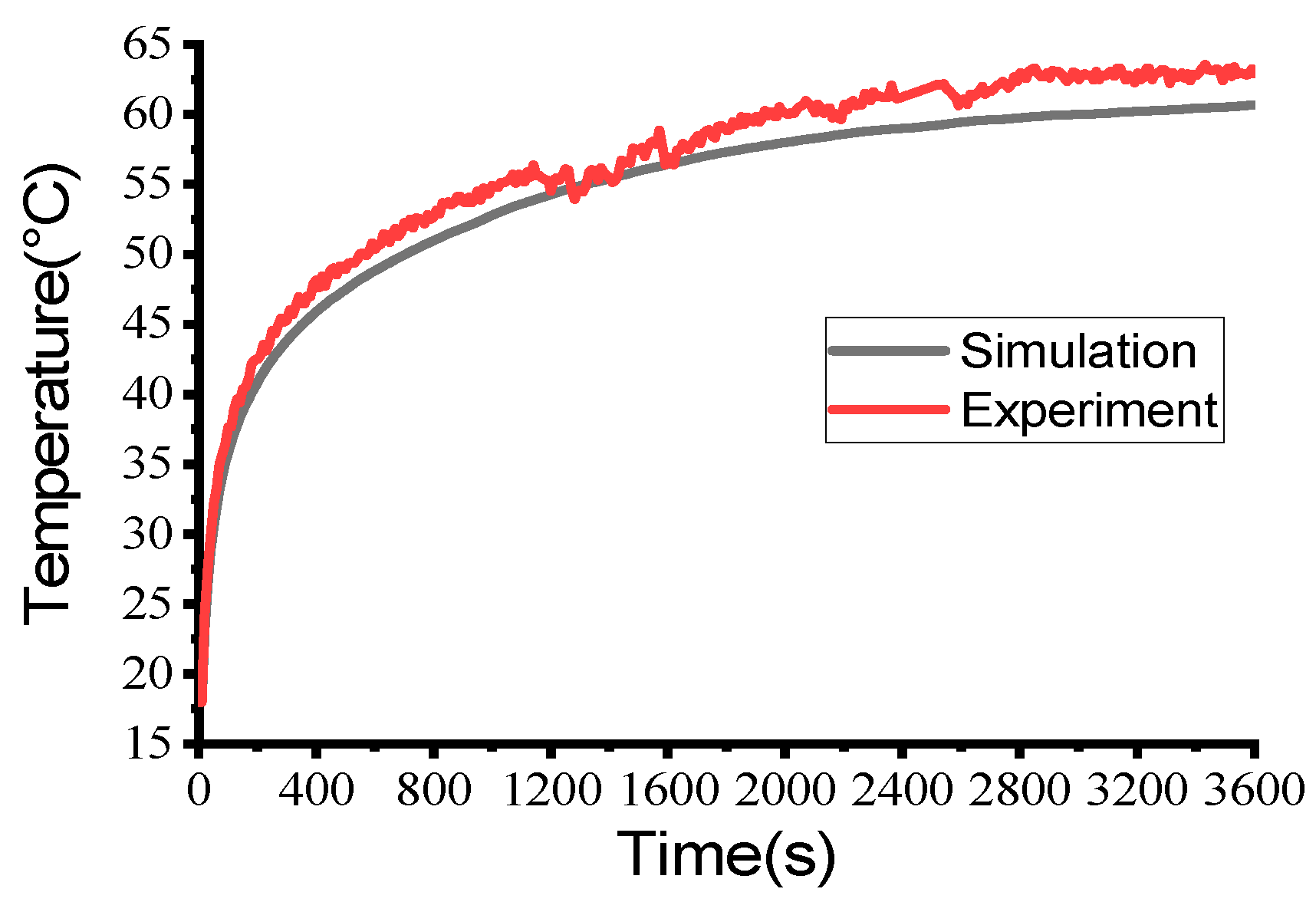
The comparison between the test and simulation results of each monitoring point is shown in Figure 13 and Figure 14, respectively. It can be seen that the test and simulation trends of each monitoring point are consistent. The test result of the main driver’s seat monitoring point is 62.9 °C, and the simulation result is 60.7 °C. The test result of the main driving seat cushion monitoring point is 33.3 °C, and the simulation result is 33 °C. The test result of the instrument panel monitoring point is 48.6 °C, and the simulation result is 45.5 °C. The simulation revealed that the temperature error of each monitoring point was within 4 °C, and the average error rate was less than 5%, which meets the needs of engineering calculations after correction.

3. Simulation of the Temperature Distribution of the Occupant Cabin

3.1. Analysis of the Influence of the Greenhouse Effect on the Temperature of the Occupant Cabin

The energy within the unit wavelength including the wavelength λ that is radiated from the unit surface area to all directions of the hemispherical space per unit time is called the spectral radiant force, denoted as E, and its unit of measurement is W/(m2·K4) [30]. Planck’s law states that the spectral radiant force of a black body changes with the wavelength λ:
E b λ = c 1 λ 5 e c 2 / ( λ T ) 1 ,
where e is the natural logarithm; T is the black body thermodynamic temperature of the object, and its unit of measurement is K; c1 is the first radiation constant, which is 3.741 × 10⁻¹⁶ W·m2; c2 is the second radiation constant, which is 1.438 × 10⁻² W·m2.
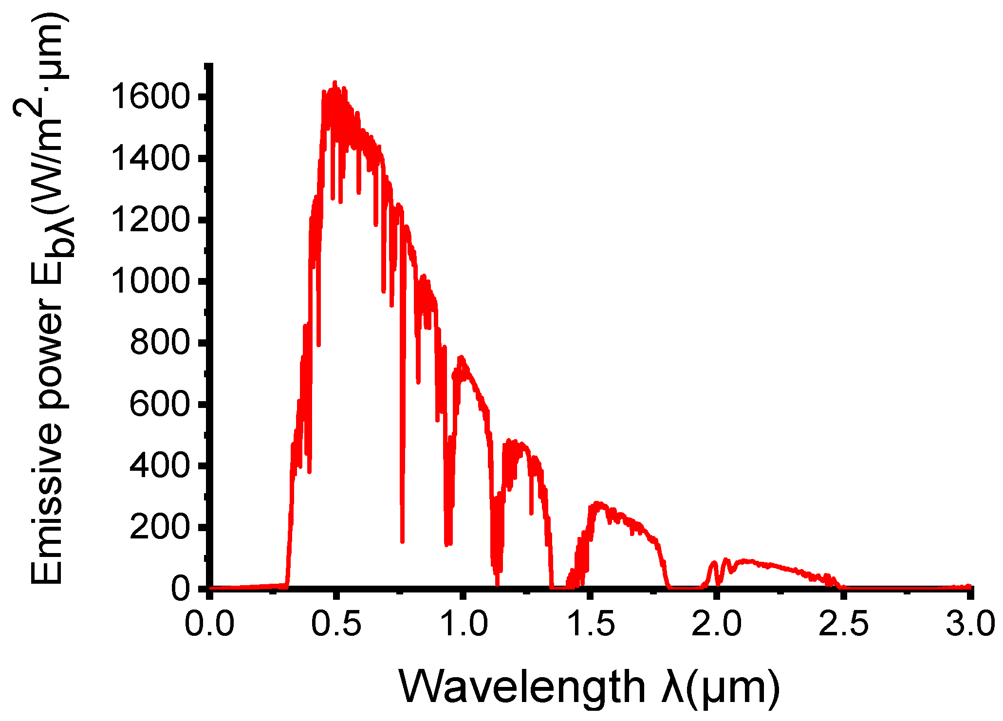
Wien’s displacement law states that the wavelength of the maximum spectral radiant force emitted by a black body is related to the temperature of the object. The higher the black body temperature, the shorter the wavelength of the maximum spectral radiant force. The surface temperature of the sun is extremely high, which can be approximately regarded as a black body of 5800 K. According to Equation (8), it can be calculated that the wavelength of the maximum spectral radiant force emitted by the sun is approximately 0.5 μm.
λ m T = 2.8976 × 10 3 μ m K ,
Figure 15 shows the spectral distribution of solar radiation according to the ASTM G177 standard [31]. It can be seen from the figure that the wavelength of the maximum spectral radiant force emitted by the sun is about 0.5 μm, which is consistent with the calculation result of Wien’s displacement law. When the radiation wavelength exceeds 2.5 μm, the solar radiation force is basically equal to 0.
According to Planck’s law and Stefan–Boltzmann’s law, the integral of spectral radiant power over wavelength is the radiant power of a black body at that temperature. Therefore, the radiant energy of a black body in a certain range can be solved by the Equation (9):
E b ( 0 λ ) = 0 λ E b λ d λ = 0 λ c 1 λ 5 e c 2 / ( λ T ) 1 d λ ,
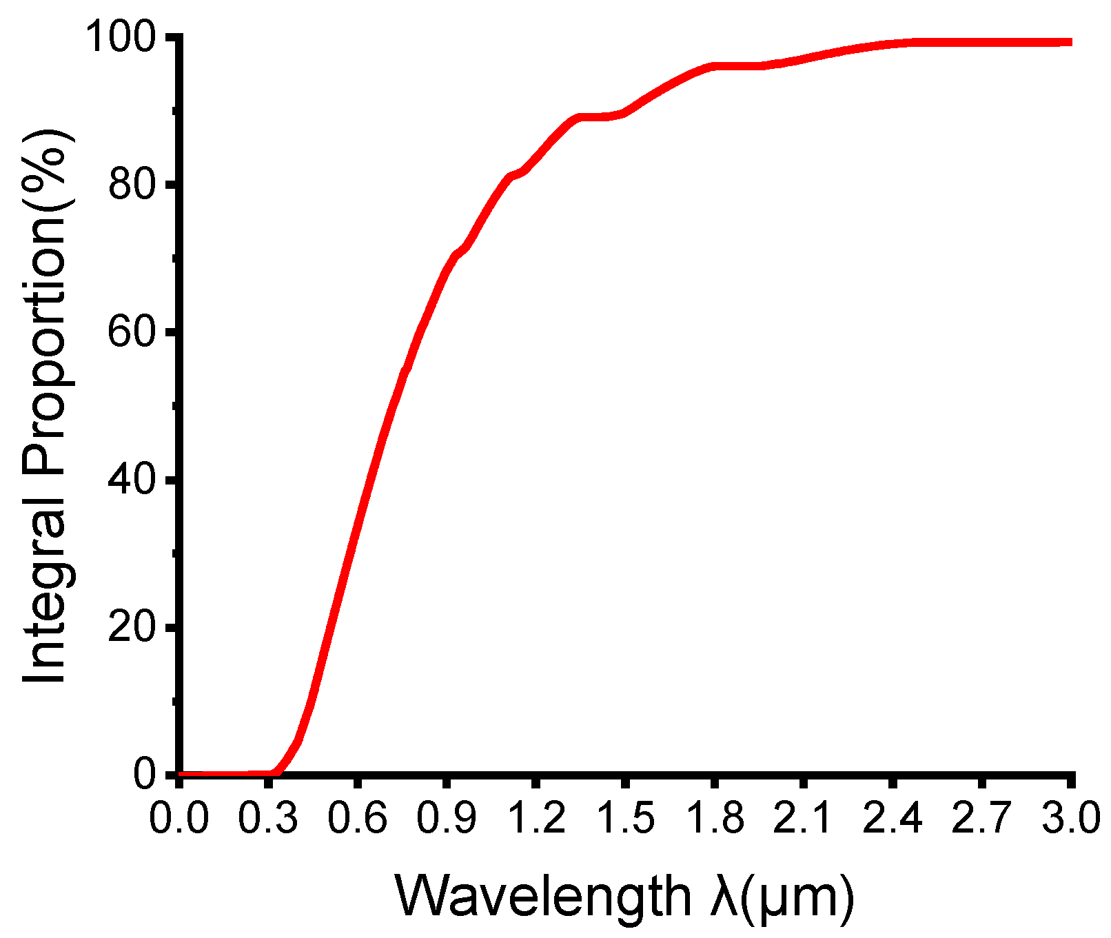
Integrating the solar spectral radiant power with the wavelength, it can be seen from Figure 16 that the solar radiation energy in the 0.2–3 μm section exceeds 99% of the total solar radiation. The temperature of the internal parts of the car is roughly in the range of 50–100 °C. According to the Equations (8) and (9), the wavelength of the maximum spectral radiation emitted by the car parts is around 7–9 μm, and it radiates in the 0–3 μm section. It can account for less than 0.1%, and the proportion in the 3–400 μm section reaches 99%.
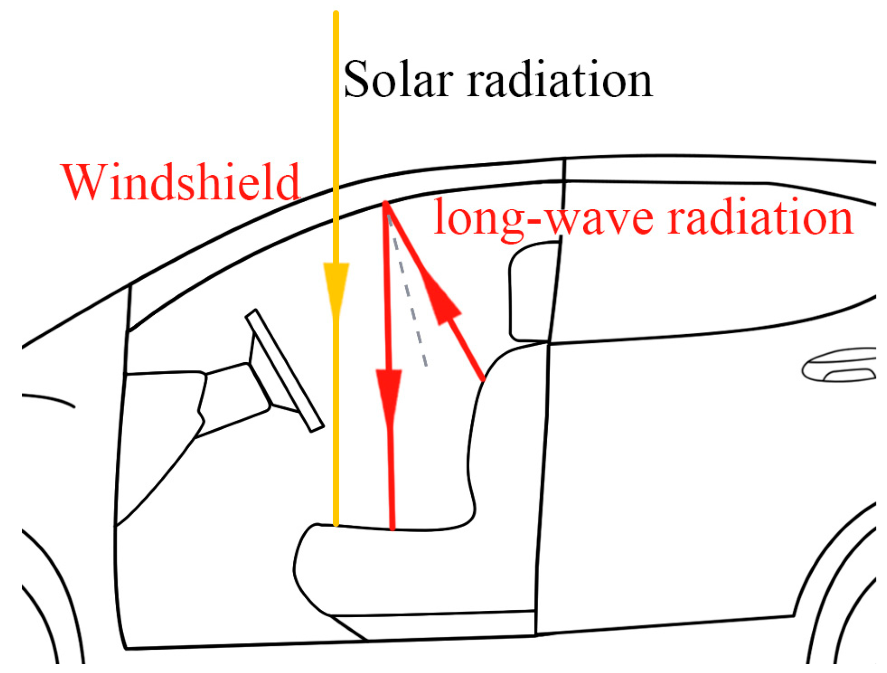
The mechanism of the formation of the greenhouse effect in the occupant cabin is shown in Figure 17. The energy of solar radiation is concentrated in the short-wave area with a wavelength of less than 3 μm, and most of the solar radiation can easily enter the occupant cabin through the window glass. The radiation wavelengths emitted by the components in the occupant cabin are concentrated in the long-wave region near 7–9 μm. The heat radiation penetration ratio of the glass to this section is very low. Absorption, which leads to the continuous accumulation of heat in the occupant cabin, forming a greenhouse effect.

3.2. Simulation of the Greenhouse Effect in the Occupant Cabin

The existence of the greenhouse effect affects the temperature of the cabin components and the air. However, in the previous thermal comfort studies of the passenger cabin, the window glass was treated as a gray body, and the greenhouse effect is not well reported in the published literature. In order to study the influence of the greenhouse effect on the cabin components and air temperature, this section selects summer conditions, treats solar radiation according to multi-section thermal radiation and divides the solar spectrum into different sections based on the transmittance of glass in different sections Two sections of 0–3 μm and 3–400 μm were used to simulate the outdoor parking temperature rise in summer.
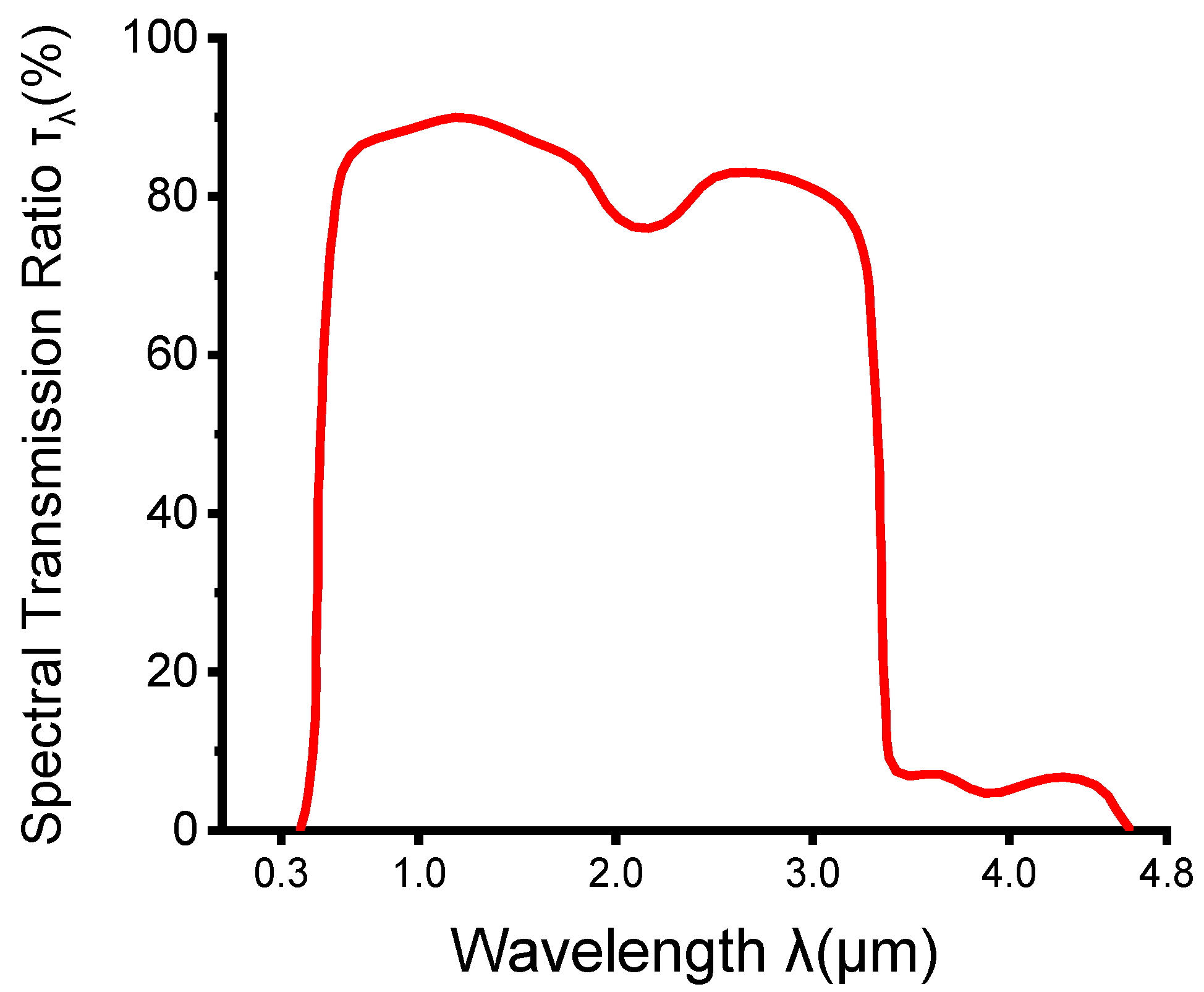
The transmittance of the car window glass is a function of the wavelength, and the transmittance is always changing with the wavelength. If a corresponding transmittance is set for each wavelength, the calculation amount will increase exponentially, which is not realistic. The relationship between the spectral penetration ratio of the car window glass and the wavelength is shown in Figure 18. The transmittance is higher in the 0–3 μm section, while the spectral transmittance ratio changes greatly at 3 μm, rapidly decreasing to about 0.1, and the transmittance changes greatly. In this paper, based on the transmittance ratio of the glass in different sections, the spectrum is divided into two sections, 0–3 μm and 3–400 μm, and the window glass is treated as gray in each section.
To investigate the influence of the greenhouse effect on temperature, the summer operating conditions in this study are taken into consideration as an example to compare the difference between the presence or absence of the greenhouse effect. Based on the multi-band heat radiation model, working condition 1 without considering the greenhouse effect and the base working condition considering the greenhouse effect are set. The wavelength-selective transmittance of the window glass is the direct cause of the greenhouse effect. Transmittance has the greatest influence on the temperature in the occupant cabin, while the absorption and reflectance have little influence, so only the transmittance of the windshield is changed. The parameters such as the absorptivity and reflectivity of the windshield glass and interior parts remain unchanged. In working condition 1, the glass is regarded as a gray body, and the glass transmittance is set to be the same in the two wavebands. In the base working condition, the glass transmittance is set to be different in the two wavebands. The optical parameters of the vehicle’s glass and the components in the occupant cabin under different working conditions are shown in Table 2 and Table 4, respectively.
For the base working condition, the transmittance of the glass at the wavelength band of 3–400 μm is low, so the solar radiation entering the occupant cabin in the base working condition is lower than that of working condition 1. However, 99% of the solar radiation energy is concentrated in the shortwave area with a wavelength varied from 0 to 3 μm. Therefore, the solar radiation energy transmitted into the occupant cabin through the window glass of the two working conditions has little difference and can be considered equal.
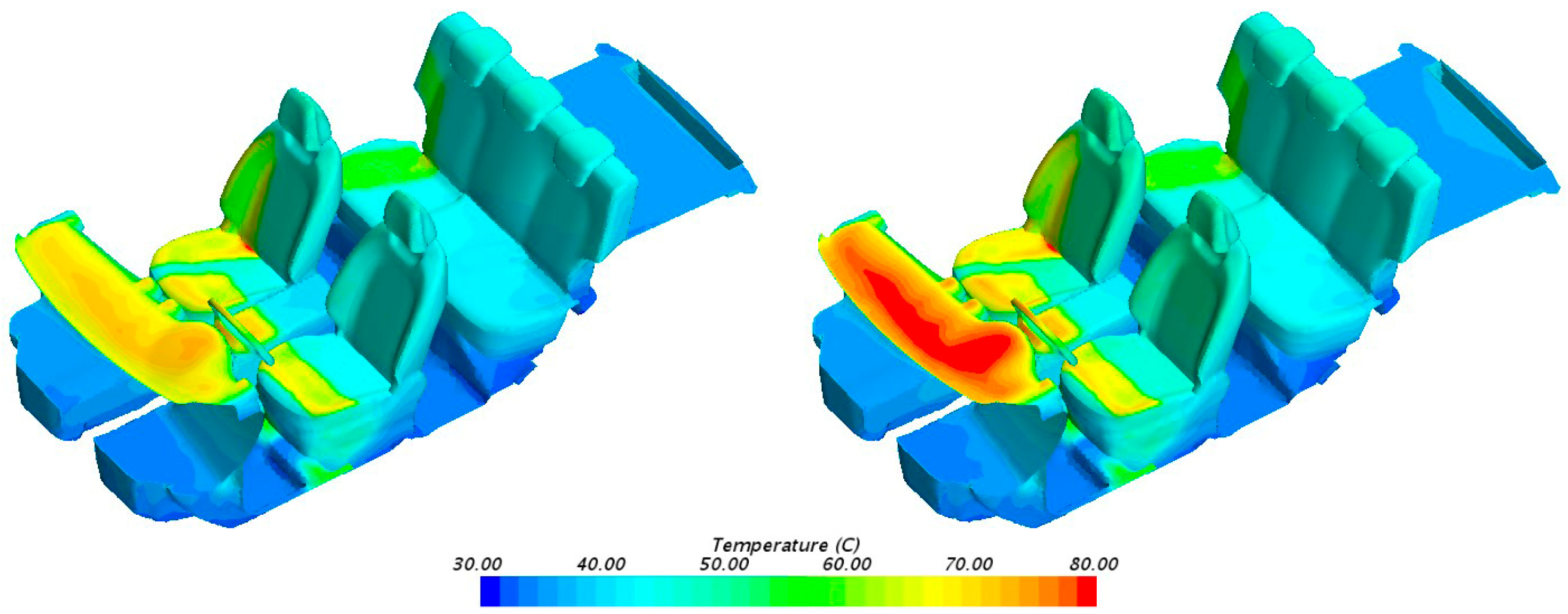
Figure 19 shows the thermal radiation in the 3–400 μm range of the occupant cabin interior parts. It can be seen that the parts near the front wind window in the base condition, such as the dashboard and seats, are subject to strong long-wave radiation, which is significantly higher than working condition 1. The reason is that the windshield glass has a low transmittance to long-wave radiation, and the long-wave radiation emitted by the interior trim parts close to the windshield is reflected back by the glass to form an accumulation effect.
Figure 20 shows the temperature distribution contour of the interior parts. By comparing the temperature difference between the interior parts, it can be seen that the temperature difference between the dashboard in the front of the occupant cabin is large under the two working conditions. The temperature of dashboard in working condition 1 is 75.3 °C, while that in base working condition is 88.1 °C, with a temperature difference of nearly 13 °C. The temperature difference between the rear seats away from the windshield is small. Therefore, the greenhouse effect mainly affects the temperature of the components near the front window glass.
The air temperature distribution contour of the Y = 0 section is shown in Figure 21. It can be seen from the figure that the air temperature of the base working condition is generally higher than that of working condition 1, and the air temperature difference in the front of the occupant cabin is even more obvious.
In most cases, there is only one driver in the car, and the thermal comfort of the car driver directly affects the driving safety, so this study also investigated the surface temperature of the driver’s seat. The seat cushion and backrest are the main parts of the seat surface, which are in close contact with the human body. Thus, this paper focuses on the temperature of the cushion and backrest of the main driver’s seat. As shown in Figure 22, the temperature of the main driver’s seat is significantly affected by the greenhouse effect. Compared with working condition 1, the average temperature of the seat backrest in the base working condition increased by 3.1 °C, and the average temperature of the seat cushion increased by 2.3 °C.
Under the same solar radiation condition, the heat load of the base working condition considering greenhouse effect is higher than that of condition 1 without greenhouse effect. The influence of the greenhouse effect is more obvious in the area near the windshield. Therefore, the use of materials with lower absorption of long-wave radiation in the passenger cabin can be considered to reduce the influence of the greenhouse effect and thus reduce the heat load of the occupant cabin.

4. Characteristics of Pre-Cooling Ventilation in Occupant Cabin

4.1. Working Condition Setting

Data related to low temperature scald show that skin damage can occur in the presence of a heat source at 49 °C for more than 3 min, and necrosis can occur after 9 min [32]. The temperature in the high-temperature area of the car seat can reach 60 °C in summer. Direct contact with the seat will not only make passengers feel too hot but even cause skin damage. The thermal comfort of the cabin can be greatly improved if the air supply function of the cabin is used to cool the cabin temperature in advance. Here, the influence of different air supply parameters on the cooling effect were considered based on the simulation conditions described in Section 3. The environmental conditions of the simulation are the same as the conditions mentioned in Section 2.
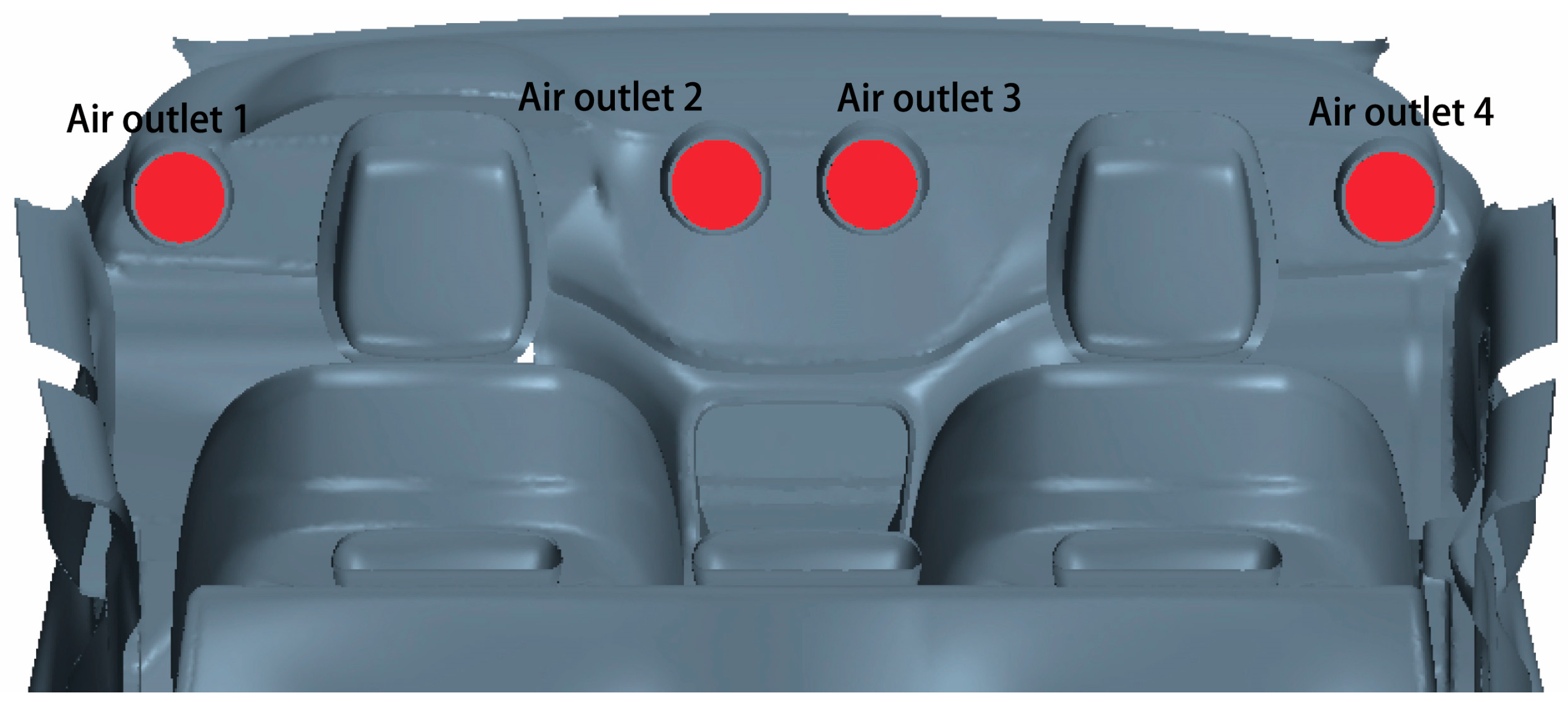
The car air conditioner used for pre-cooling includes 4 air conditioning outlets, the specific positions of which are shown in Figure 23. The air conditioning system is turned off. The supply air temperature of each working condition is always maintained at an ambient temperature of 30 °C. The controlled variable method is used to study the influence of each variable on the cooling effect. When the influence of a certain supply air parameter is studied, other supply air parameters remain unchanged. Air temperature and seat temperature are the main factors that affect the thermal comfort of passengers. Therefore, the ventilation cooling time is set to 5 min to investigate the influence of air supply parameters on the cooling effect of air and seat.
When studying the influence of air supply volume on cooling, other parameters should be kept unchanged except for air supply volume. The air supply temperature is the ambient temperature of 30 °C. The longitudinal air supply angle is the original angle of 14.5°. The horizontal air supply angle is maintained at 0°. The air supply time is 5 min. Since no occupants are in the car during the pre-cooling, it is not necessary to consider whether the wind speed will affect the thermal comfort of the occupants when analyzing the cooling effect. In this paper, nine working conditions with the total air supply Q from 100 to 900 m3/h are set, and the air supply of each air outlet remains the same, which is 1/4 of the total air supply. The working condition without ventilation and cooling is named working condition 0, and the air supply rate of each working condition is shown in Table 5.

4.2. Simulation Analysis of the Average Air Temperature in the Occupant Cabin

Prior studies (reported in the open-source literature) on the thermal comfort of the occupant cabin mainly focused on the manned condition, and the thermal comfort of the occupant cabin was optimized based on the evaluation indexes of human thermal comfort such as PMV, Teq and TSV [33]. When the occupant cabin is manned, the air supply parameters such as wind speed and temperature should meet the cooling effect, and the wind speed and temperature should not be too high, so as not to reduce the thermal comfort of the cabin. However, there is no occupant in the car during pre-cooling, so the prior thermal comfort evaluation index is not applicable. In order to measure the cooling effect of different air supply parameters on the air in the occupant cabin, the cooling rate η defined in the equation is used as an evaluation index in this paper.
η = T base T T base
In the equation, Tbase is the temperature of a component in the occupant cabin at a certain moment in the base condition without pre-cooling, and T is the temperature of the same component in the pre-cooling condition at the same time. For the occupant cabin after a hot soak, its internal temperature greatly exceeds the comfort zone. Therefore, within a certain range, the greater the cooling rate, the closer the cabin temperature to the comfort zone.
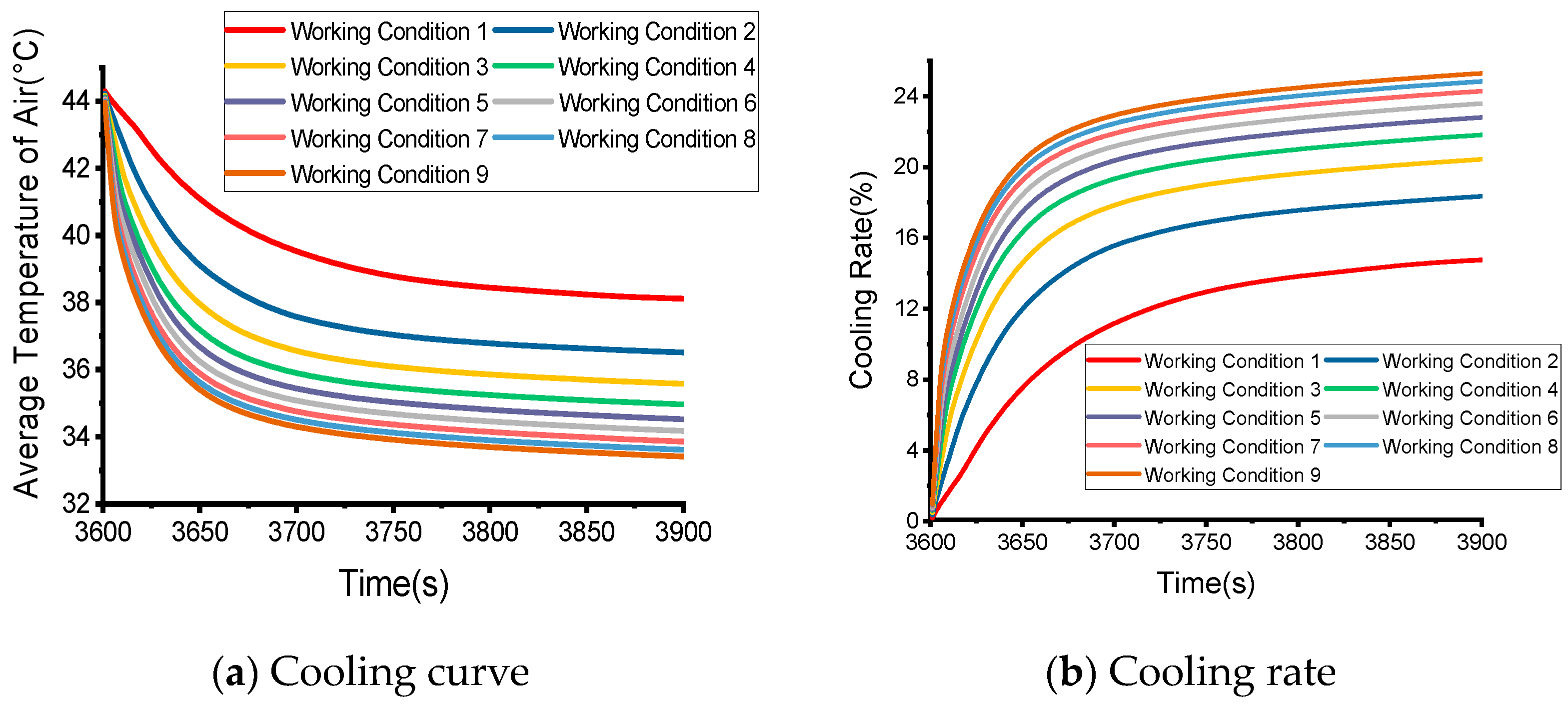
The cooling curve and cooling rate of the average air temperature under different working conditions are shown in Figure 24. During the 5 min from 3600 s to 3900 s, the average air temperature in base condition without cooling increases from 44.3 °C to 44.7 °C. The average air temperature in the car far exceeded the upper limit of the human body’s comfortable temperature. The average air temperature reduction rate of various cooling conditions shows a trend of fast first and then slow. The temperature reduction in the first minute of each cooling condition accounts for more than 80% of the total temperature reduction, and the temperature reduction in the last 4 min increases slowly and gradually becomes stable. Different air supply volumes have great influence on the cooling rate, showing a trend that the greater the total air supply volume, the better the cooling effect. However, the cooling rate does not increase proportionately with the increase in the air supply volume. When the total air supply volume increases, the increase in the cooling rate declines gradually. When the air supply volume reaches a higher value, the cooling rate tends to be stable. When the air supply volume increases from 700 m3/h to 900 m3/h, the average air temperature only decreases by 0.45 °C. It can be considered that the cooling effect tends to be stable when the air supply volume reaches 700 m3/h.
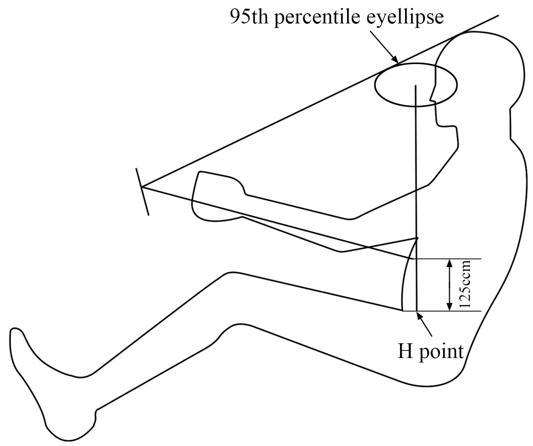
When the air supply volume reaches 700 m3/h, the cooling effect of the air is stabilized, and increasing the air supply volume has little impact on the cooling effect. Therefore, when studying the influence of different longitudinal air supply angles on the cooling effect of air in this section, the total air supply is 700 m3/h. As shown in Figure 21, it is evident that the air in the occupant cabin is obviously stratified in the Z-direction after exposure to the sun. Hot air is suspended in the upper space of the occupant cabin, and the lower temperature air settles in the lower space. Thus, adjusting the longitudinal angle of the air outlet of the air conditioner may affect the cooling rate. Figure 25 shows the adjustable range of the longitudinal air supply angle of the automobile air conditioner. The adjustable range of the longitudinal air supply angle of a general automobile air conditioner is shown in Figure 25. The top is tangent to the 95th percentile eyellipse, and the bottom reaches 125 cm above the H point.
According to the adjustable angle of the car air conditioner, this study considered five working conditions to explore the influence of different longitudinal air supply angles on the air cooling effect. The angle is positive when the horizontal line x is upward, and negative when it is downward. The air supply temperature is always the ambient temperature of 30 °C, the horizontal air supply degree is maintained at 0°, and the air supply time is 5 min. The longitudinal air supply angle of each working condition is shown in Table 6.
The cooling effect of different longitudinal air supply angles on the air temperature is shown in Figure 26. The experimental data show that different air supply angles have little effect on air cooling, whether it is a cooling rate or final temperature. Working condition 2 has the best cooling effect with a final temperature of 33.86 °C. Working condition 5 has the worst cooling effect with a temperature of 34.05 °C and only a 0.19 °C difference. The cooling trend of each condition is similar, and the temperature decrease mainly occurs in the early stage. The cooling amount in the first minute accounts for more than 80% of the total temperature reduction. In the later stage, the cooling rate is low, and the temperature gradually tends to remain stable, basically in the state of thermal equilibrium. Therefore, the longitudinal air supply angle has little influence on the average air temperature.
For the average air temperature, the cooling effect is mainly determined by the air supply volume. The greater the total air supply volume, the better the cooling effect. However, as the air supply volume increases, the effect of increasing the cooling rate gradually weakens, and the cooling effect gradually stabilizes. For the air supply angle, when changing the vertical or horizontal air supply angle, the impact on the cooling effect is very limited.

4.3. Simulation Analysis of the Average Temperature of the Seat

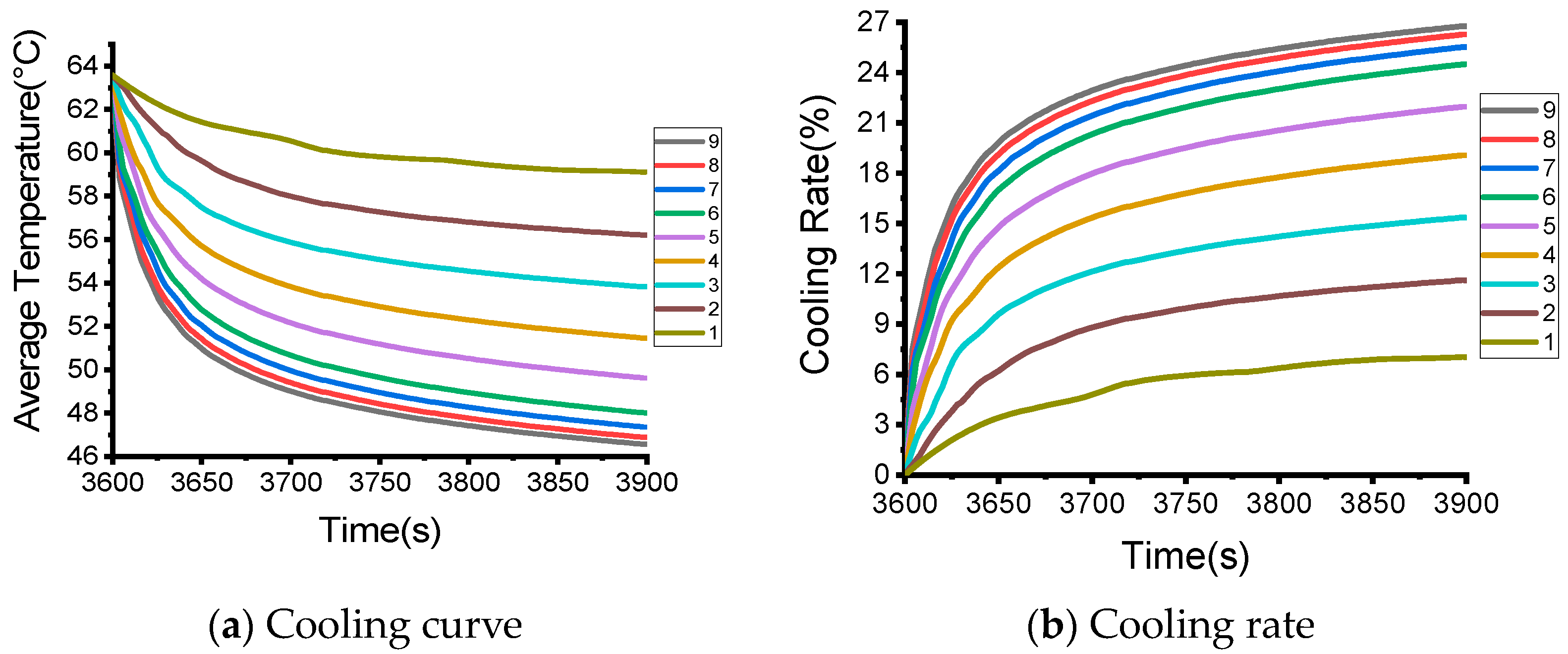
The cooling curve and cooling rate of the driver’s backrest temperature under various working conditions are illustrated in Figure 27. Different air supply volumes have different impacts on the backrest cooling rate, which is similar to the average air temperature. The larger the total air supply volume, the better the cooling effect. The cooling effect is the worst in the working condition when the air supply is 100 m3/h. The backrest temperature is 59.1 °C, which is 5.48 °C lower than the base working condition, and the cooling rate is 8.48%. The air supply effect of 900 m3/h is the best with a backrest temperature of 46.6 °C, which is 18 °C lower than that for the base working condition, and a cooling rate of 27.9%. When the total air supply is low, increasing the air supply can significantly increase the cooling rate. However, as the total air supply increases, the increase in the cooling rate gradually declines. From working condition 7 to working condition 9, the cooling rate increased from 26.7% to 27.9%. It can be considered that when the air supply reaches 700 m3/h, the cooling effect is stable.
Figure 28 shows the cooling curve and cooling rate of the driver’s seat cushion temperature under various working conditions. In 5 min, the average temperature of the driver’s seat cushion in the base condition increased by 0.7 °C, reaching a high temperature of 67.6 °C. Regardless of the cooling trend or the cooling rate, the seat cushion is similar to the backrest. The cooling rate of each working condition in the first 3 min of air supply reaches 80% of the total cooling rate. In terms of the cooling rate, it also shows that the larger the total air supply, the better the cooling effect. However, as the air supply volume increases, the effect of the air supply volume on the cooling rate is continuously weakened. The seat cushion temperature difference between working condition 7 and working condition 9 is only 0.76 °C. It can also be considered that when the air supply reaches 700 m3/h, the cooling effect becomes stable.
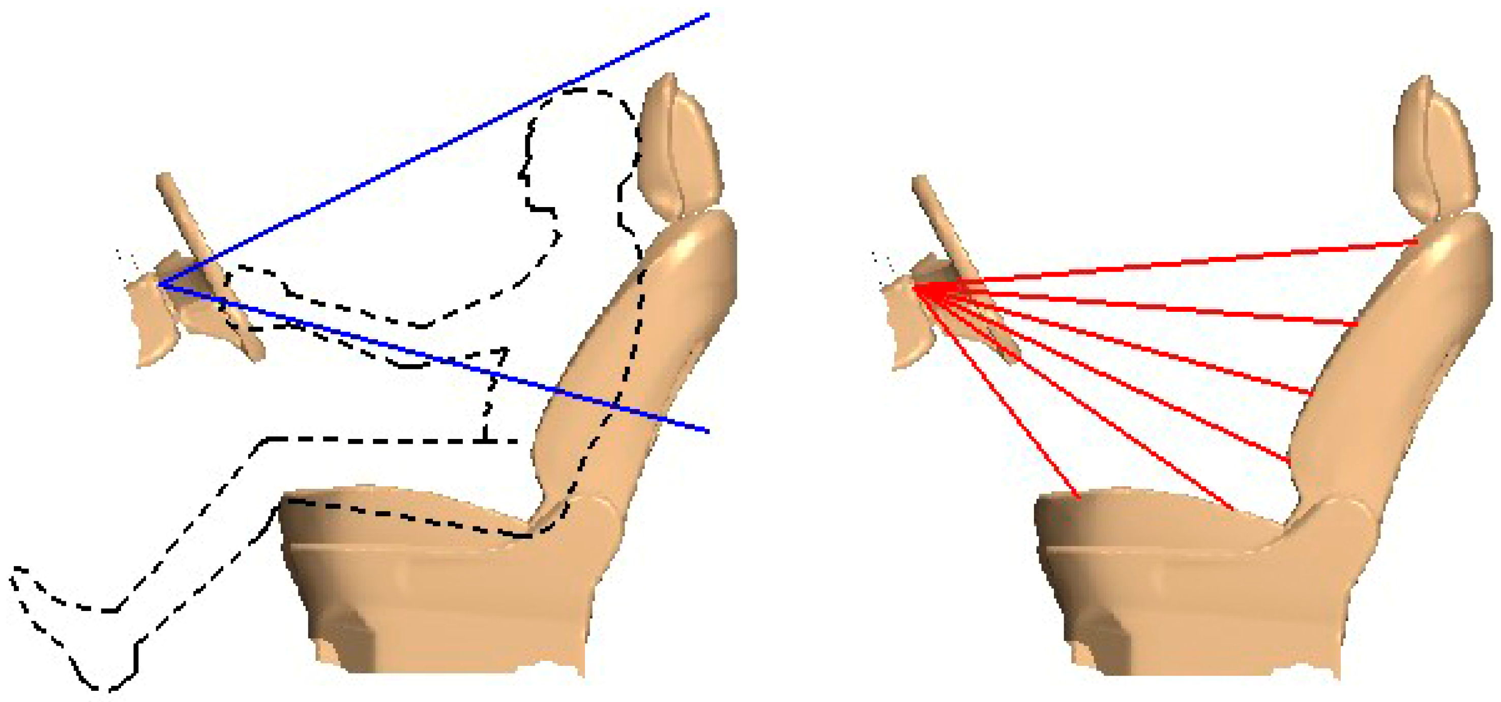
The traditional air supply range of automobile air conditioning is designed with human body as reference, and the range that can be covered is shown on the left in Figure 29. Air supply range is limited to seat coverage, seat cushion and other positions which cannot be directly blown by the air. Here, the influence of the longitudinal air supply angle on the cooling effect under unmanned condition was explored. Because the traditional air supply angle of automobile air conditioning cannot meet the research needs, the longitudinal air supply angle is adjusted in this investigation. The adjusted range is the area covered by the red lines on the right in Figure 29. By changing the longitudinal air supply angle of the air conditioner, the optimal air supply angle for the cooling of the main driver seat in different directions is investigated.
Different models of air conditioning have different air outlet locations and different seat shapes. In order to make the study of longitudinal air supply angle more universal, regional fuzzy modeling for each precise angle is required. The coverage of the seat by each angle of the air supply port is shown on the right in Figure 29. When the air supply angle is 5°, the flow from the air supply port connects with the seat at the top of the backrest. Similarly, when the air supply angles are −5°, −15°, −25°, −35° and −45°, the air flow from the air supply port connects with the seat at the upper part of the backrest, the middle part of the backrest, the lower part of the backrest, the back of the seat cushion and the front of the seat cushion.
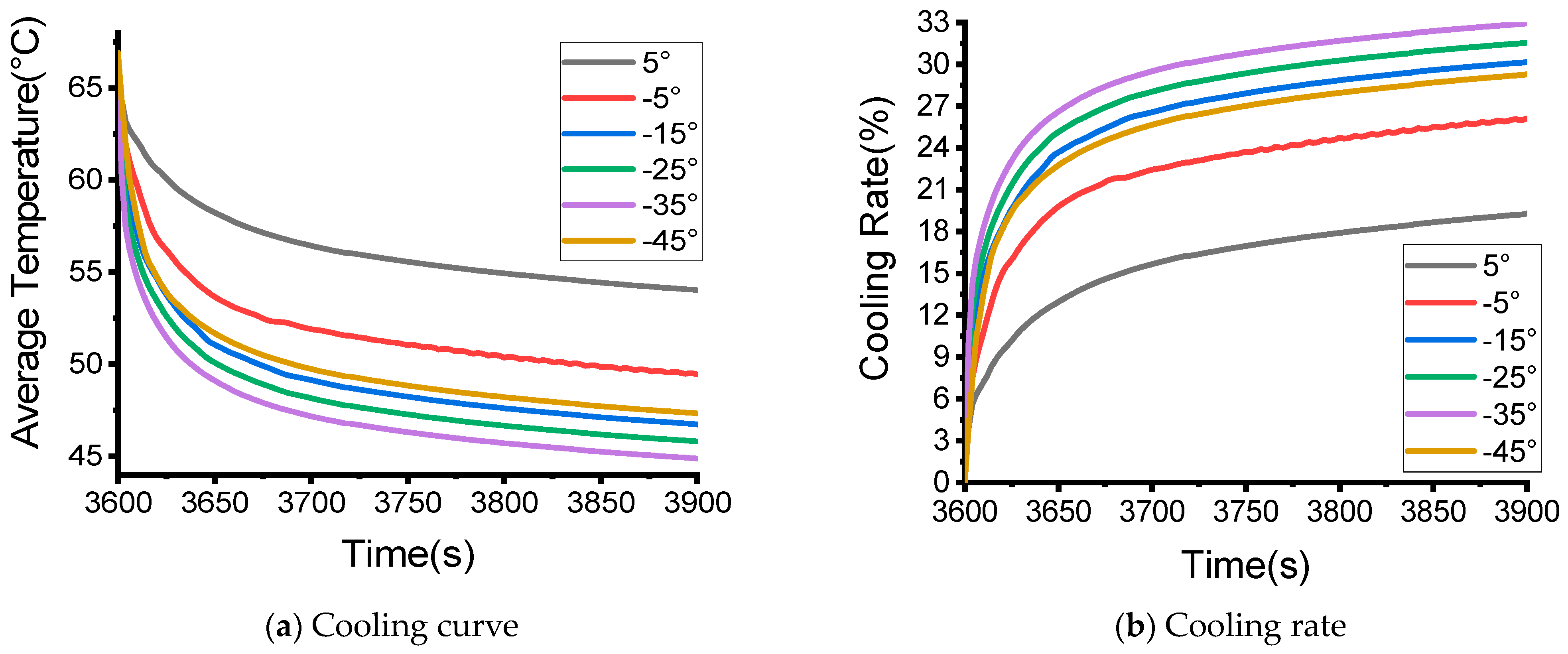
Figure 30 and Figure 31 show the cooling curves and cooling rates of the backrest and seat cushion, respectively. The data indicate that within 5 min, the temperature of the driver’s backrest increased from 63.59 °C to 64.59 °C. Different longitudinal air supply angles have a large difference in the cooling effect on the backrest. The driver’s backrest has the best cooling effect when the longitudinal air supply angle is −15° with a corresponding temperature of 39.79 °C and a cooling rate of 38.4%. At the same time, the temperature of the driver’s seat cushion increased from 66.92 °C to 67.92 °C. Different longitudinal air supply angles have a great difference in the cooling effect on the seat cushion. The driver’s seat cushion has the best cooling effect when the longitudinal air supply angle is −35° with a corresponding final temperature of 44.87 °C and a cooling rate of 33.64%.
For the air in the passenger cabin, the cooling effect is mainly determined by the air supply volume, and the air supply angle has a limited impact on the cooling effect. Similarly, for the driver’s seat, the air supply volume and air supply angle have important influence on the cooling effect. The greater the total air supply, the better the cooling effect, but as the air supply increases, the effect of increasing the cooling rate gradually weakens. The change in the air supply angle of the air outlet changes the flow field distribution near the seat surface, and the average cooling rate can be improved by adjusting the air supply angle reasonably.

5. Conclusions

In the work presented here, a sports utility vehicle (SUV) was used as the research object. Firstly, a test of temperature rise in the occupant cabin of the vehicle due to outdoor exposure was conducted. The environmental parameters and test results during the test were statistically analyzed to provide the boundary conditions and validation data for the subsequent numerical simulations. The temperature distribution of the occupant cabin was obtained by the numerical simulation and compared with the experimental results, which proved the accuracy of the simulation. The greenhouse effect of the occupant cabin under the sun exposure was explored, and the law of the temperature distribution of the occupant cabin was obtained, which provided a reference for reducing the temperature. Based on the thermal environment of the occupant cabin after the exposure to a temperature rise, an evaluation index for the average cooling rate was proposed, and the influence of different air supply volumes and angles on the cooling effect of the occupant cabin during the ventilation and cooling process was explored.
In other recent research mentioned in this paper with respect to the thermal comfort of the vehicle cabin, the authors generally studied the performance of the air conditioner, such as the structure of the air conditioning duct and air supply conditions. Furthermore, in recent research, most of the working conditions studied were manned. However, there is always a sharp increase in the temperature of the vehicle cabin after undergoing the hot soak conditions. Due to the limitations of the cooling capacity and energy consumption of the existing automobile air-conditioning system, it takes a long time from the moment the occupant gets in the vehicle till the moment when the temperature drops to the comfort level, and this period was often overlooked in previous studies. Different from the thermal comfort of the passenger compartment under manned conditions, this paper studies the pre-ventilation condition of an unattended occupant cabin. In contrast to recent research progress, this study found that the pre-ventilation of unmanned occupant cabin can improve the comfort of the occupants when they first get in the vehicle under the hot soak conditions. In this paper, the temperature distribution in the unmanned occupant cabin of a parked automobile and the influence of the air supply parameters on the cooling effect were studied, and the law of temperature distribution in the occupant cabin was obtained for accurate computational modeling of pre-ventilation, thus providing a reference for the design of the pre-cooling function for the vehicle cabin as described in Section 1. The major findings of this study are as follows:
(a)
There are large differences in the surface convective heat transfer coefficients of different parts of the vehicle body, and there are large errors in their solution using empirical formulas. The solution accuracy can be improved by establishing a virtual wind tunnel and using the CAS model outside the vehicle body.
(b)
At the same solar radiation intensity, compared to gray body heat radiation, a multi-band heat radiation model that takes into account the greenhouse effect shows an increase in the overall temperature of the passenger cabin. For areas close to the front windshield, such as front seats and dashboards, etc., the impact of the greenhouse effect is more significant.
(c)
In the process of ventilation and cooling, the cooling effect of the air in the passenger cabin is mainly determined by the air supply volume, and the air supply angle has a limited impact on the cooling effect. For the driver’s seat, adjusting the air supply volume and air supply angle has a great impact on the cooling effect. The larger the total air supply, the better the cooling effect. However, as the air supply increases, the effect of increasing the cooling rate gradually weakens. Adjusting the air supply angle of the air outlet can change the flow field distribution near the seat surface, and the average cooling rate can be improved by adjusting the air supply angle reasonably, which can reduce energy consumption.

Author Contributions

Conceptualization, Z.L. and S.L.; methodology, Y.Z., Z.L. and S.L.; software, Z.L. and S.L.; validation, Y.Z., G.W. and H.C.; formal analysis, Z.L. and S.L.; investigation, Z.L. and S.L.; resources, Y.Z.; data curation, Z.L. and S.L.; writing—original draft preparation, Z.L.; writing—review and editing, Y.Z.; visualization, S.L.; supervision, G.W. and H.C.; project administration, Y.Z.; funding acquisition, Y.Z. All authors have read and agreed to the published version of the manuscript.

Funding

This research was funded by the project of National Key R&D Program of China (grant NO.2018YFA0703300), Changsha Automobile Innovation Research Institute Innovation Project, Jilin University (NO. CAIRIZT20220306), The National Natural Science Foundation of China (NO.11702109 and NO.11772140) and Open Foundation of State Key Laboratory of Automotive Simulation and Control, Jilin University (NO.20191104).

Data Availability Statement

The data presented in this paper are available on request from the first author.

Acknowledgments

The authors would like to thank their laboratory team member for assistance. The authors would also like to thank Firoz Alam for suggestions for the revision of the manuscript and generous help in English improvement.

Conflicts of Interest

The authors declare no conflict of interest.

References

  1. Al-Kayiem, H.H.; Sidik, M.F.B.M.; Munusammy, Y.R. Study on the Thermal Accumulation and Distribution Inside a Parked Car Cabin. Am. J. Appl. Sci. 2010, 7, 784–789. [Google Scholar] [CrossRef]
  2. Wyon, D.P.; Wyon, I.; Norin, F.J.E. Effects of moderate heat stress on driver vigilance in a moving vehicle. Ergonomics 1996, 39, 61–75. [Google Scholar] [CrossRef] [PubMed]
  3. Lenzuni, P.; Capone, P.; Freda, D.; Del Gaudio, M. Is driving in a hot vehicle safe? Int. J. Hyperth. 2014, 30, 250–257. [Google Scholar] [CrossRef] [PubMed]
  4. Grundstein, A.; Dowd, J.; Meentemeyer, V. Quantifying the Heat-Related Hazard for Children in Motor Vehicles. Bull. Am. Meteorol. Soc. 2010, 91, 1183–1191. [Google Scholar] [CrossRef]
  5. Li, L. Simulation and Experimental of Vehicle Cabin and Components Thermal Load under Natural Exposure. Master’s Thesis, South China University of Technology, Guangzhou, China, 2015. [Google Scholar]
  6. Hu, C. A Study of the Characteristics of Sunning and Ventilation Cooling in Parked Vehicle. Master’s Thesis, Huazhong University of Science and Technology, Wuhan, China, 2016. [Google Scholar]
  7. Ravindra, K.; Agarwal, N.; Mor, S. Assessment of thermal comfort parameters in various car models and mitigation strategies for extreme heat-health risks in the tropical climate. J. Environ. Manag. 2020, 267, 110655. [Google Scholar] [CrossRef] [PubMed]
  8. Mezrhab, A.; Bouzidi, M. Computation of thermal comfort inside a passenger car cabin. Appl. Therm. Eng. 2006, 26, 1697–1704. [Google Scholar] [CrossRef]
  9. Lahimer, A.A.; Alghoul, M.A.; Sopian, K. Potential of Solar Reflective Cover on Regulating the Car Cabin Conditions and Fuel Consumption. Appl. Therm. Eng. 2018, 143, 59–71. [Google Scholar] [CrossRef]
  10. Dadour, I.R.; Almanjahie, I.; Fowkes, N.D.; Keady, G.; Vijayan, K. Temperature variations in a parked vehicle. Forensic Sci. Int. 2011, 207, 205–211. [Google Scholar] [CrossRef] [PubMed]
  11. Zhou, X.; Lai, D.; Chen, Q. Experimental investigation of thermal comfort in a passenger car under driving conditions. Build. Environ. 2018, 149, 109–119. [Google Scholar] [CrossRef]
  12. Chen, S.; Du, B.; Li, Q.; Xue, D. The influence of different orientations and ventilation cases on temperature distribution of the car cabin in the hot soak. Case Stud. Therm. Eng. 2022, 39, 102401. [Google Scholar] [CrossRef]
  13. Marshall, G.J.; Mahony, C.P.; Rhodes, M.J.; Daniewicz, S.R.; Tsolas, N.; Thompson, S.M. Thermal Management of Vehicle Cabins, External Surfaces, and Onboard Electronics: An Overview. Engineering 2019, 5, 954–969. [Google Scholar] [CrossRef]
  14. Tan, L.; Yuan, Y. Computational fluid dynamics simulation and performance optimization of an electrical vehicle Air conditioning system. Alex. Eng. J. 2022, 61, 315–328. [Google Scholar] [CrossRef]
  15. Hariharan, C.; Sanjana, S.; Saravanan, S.; Sundar, S.S.; Prakash, A.S.; Raj, A.A. CFD studies for energy conservation in the HVAC system of a hatchback model passenger car. Energy Sources Part A Recovery Util. Environ. Eff. 2019, 45, 4724–4741. [Google Scholar]
  16. Lu, K.; Gu, Z.; Jia, X.; Yin, Y. Analysis and Improvement of the Effects of Air-conditioning System on the Thermal Comfort of Passenger Cabin in a Heavy Truck. Automot. Eng. 2011, 33, 162–166. [Google Scholar]
  17. Gu, Z.; Shen, H.; Yang, Z.; Yin, Y. Improvement of vehicle air-conditioning duct and analysis of its impact on occupant thermal comfort. J. Chongqing Univ. 2013, 36, 91–96. [Google Scholar]
  18. Wang, J.; Xue, C.; Hu, X.; Cao, J.; Yue, L.; Shi, R. Simulation of airflow in passenger cabin based on air-conditioning supply parameters. J. Jilin Univ. (Eng. Technol. Ed.) 2017, 47, 50–57. [Google Scholar]
  19. Khatoon, S.; Kim, M.-H. Thermal Comfort in the Passenger Compartment Using a 3-D Numerical Analysis and Comparison with Fanger’s Comfort Models. Energies 2020, 13, 690. [Google Scholar] [CrossRef]
  20. Tobias, D.; Pascal, L.; Andre, V.; Daniel, S.; Mikhail, K.; Johannes, B. Vertical ventilation concepts for future passenger cars. Build. Environ. 2018, 129, 142–153. [Google Scholar]
  21. Lyu, H.; Chen, B.; Gao, T.; Li, Y.; Shi, J.; Chen, J. Analysis on Thermal Comfort in Car Passenger Cabin Based on Flow Field and Temperature Field. Automot. Eng. 2020, 42, 234–239. [Google Scholar]
  22. Sen, S.; Selokar, M. Numerical Simulation and Validation of Cabin Aiming and Cool-Down of a Passenger Car. Sae Int. J. Passeng. Cars-Mech. Syst. 2016, 9, 52–61. [Google Scholar] [CrossRef]
  23. Tang, J.; Gu, Z.; Mo, Z.; Wen, Q.; Zhang, S. Optimization of vehicle air-conditioning grilles and the improvement of passenger thermal comfort. J. Hefei Univ. Technol. (Nat. Sci.) 2016, 39, 309–313, 394. [Google Scholar]
  24. Singh, O.P.; Raut, R.; Biswas, M.; Singh, R. Effect of Dynamic Vents on the Thermal Comfort of a Passenger Car. Stroj. Vestn.-J. Mech. Eng. 2015, 61, 561–570. [Google Scholar] [CrossRef]
  25. Zhao, J. Design and Implementation of Communication Module for Car Air-Conditioning Remote Control System Based on FPGA. Master’s Thesis, Jilin University, Changchun, China, 2012. [Google Scholar]
  26. Guo, P.; Hu, X.; Gao, H.; Wang, M.; Sang, T.; Wang, J.; Cao, J. Influence of Parked Car Ventilation Parameters on Driver Cabin Cooling after Hot Soak. J. South China Univ. Technol. (Nat. Sci. Ed.) 2020, 48, 76–83. [Google Scholar]
  27. Chen, Z.; Qian, J.; Ye, Y. Predicting Theory of Effective Thermal Conductivity of Complex Material. J. Univ. Sci. Technol. China 1992, 22, 416–424. [Google Scholar]
  28. Zhen, J.; Guo, Q.; Zhou, J. Simulation of Heat Transfer in Multi-Layered Medium. Appl. Phys. 2019, 9, 7–12. [Google Scholar] [CrossRef]
  29. Li, G.; Ma, H. Numerical Simulations for the Laminar Natural Convection of High Rayleigh Numbers in an Enclosure. J. Huazhong Univ. Sci. Technol. 2004, 3, 14–17. [Google Scholar]
  30. Tao, W. Thermal, 5th ed.; Higher Education Press: Beijing, China, 2019; pp. 154–196. [Google Scholar]
  31. Standard Tables for Reference Solar Spectral Irradiance: Direct Normal and Hemispherical on 37° Tilted Surface. Available online: https://www.astm.org/standards/g173 (accessed on 5 May 2023).
  32. Shi, J.; Qi, W.; Xu, Q.; Zhou, S.; Wang, G. Etiological Analysis of Subambient Temperature Burn in 351 Cases of Hefei Area. Chin. J. Reparative Reconstr. Surg. 2010, 24, 665–667. [Google Scholar]
  33. Danca, P.; Vartires, A.; Dogeanu, A. An Overview of Current Methods for Thermal Comfort Assessment in Vehicle Cabin. Energy Procedia 2016, 85, 162–169. [Google Scholar] [CrossRef]
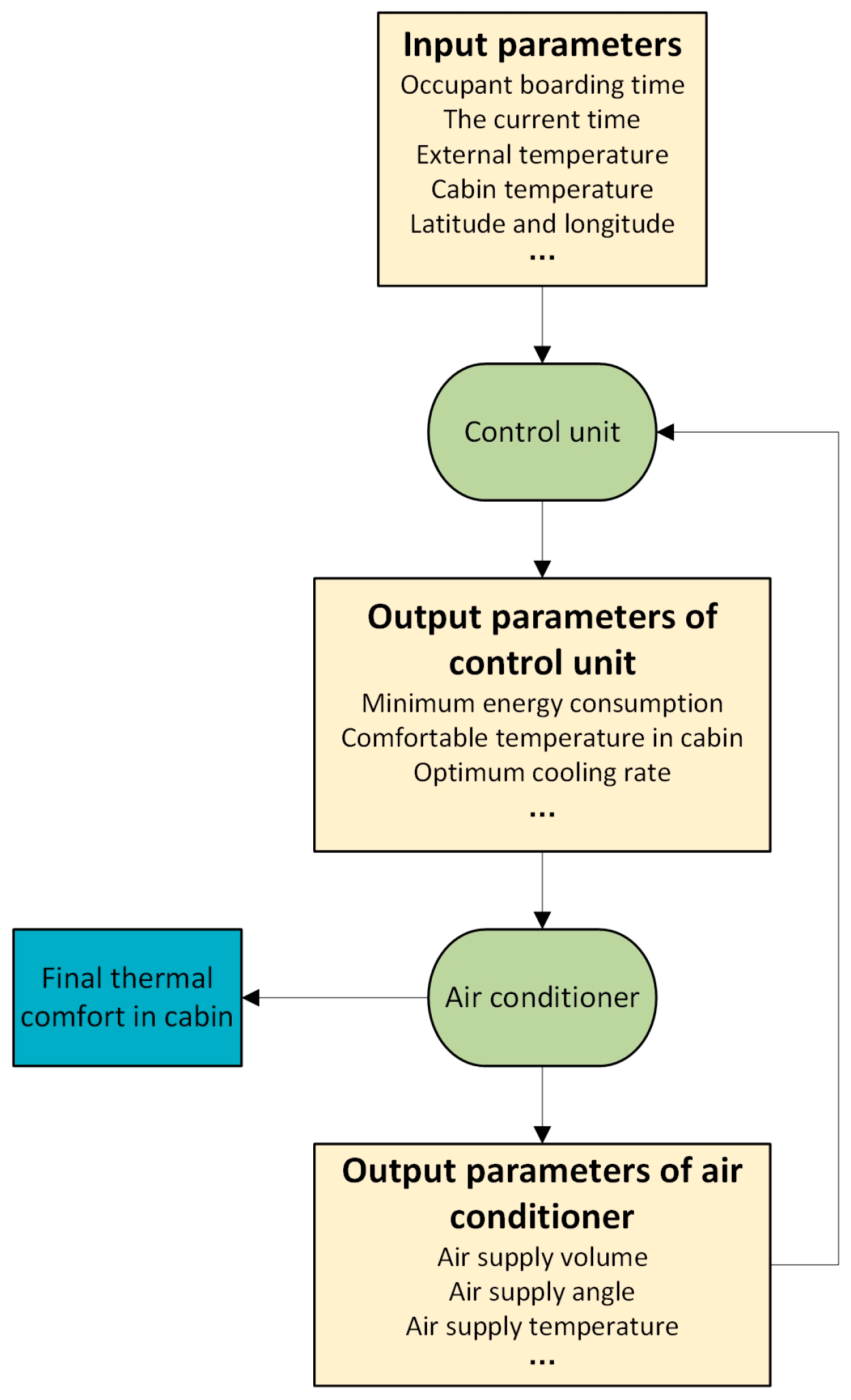
Figure 1. Theoretical model framework of cabin temperature control system.
Energies 16 07154 g001
Figure 2. The equipment in this experiment: (a) pyranometer; (b) K-type thermocouple; (c) GM data acquisition system.
Energies 16 07154 g002
Figure 3. Schematic diagram of the positions of the seat monitoring points.
Energies 16 07154 g003
Figure 4. Schematic diagram of the monitoring position on the dashboard.
Energies 16 07154 g004
Figure 5. Position of the test vehicle and the instrument.
Energies 16 07154 g005
Figure 6. Solar radiation intensity.
Energies 16 07154 g006
Figure 7. Temperature of the environment.
Energies 16 07154 g007
Figure 8. Heat transfer model of occupant cabin in outdoor parking condition.
Energies 16 07154 g008
Figure 9. Schematic diagram of external CAS division.
Energies 16 07154 g009
Figure 10. Schematic diagram of interior division.
Energies 16 07154 g010
Figure 11. Size of wind tunnel in virtual domain.
Energies 16 07154 g011
Figure 12. Equalization of heat transfer coefficient on car body surface.
Energies 16 07154 g012
Figure 13. Comparison of experiment results and simulation results of the main driver’s seat monitoring points.
Energies 16 07154 g013
Figure 14. Comparison of test results and simulation results of the main driver’s seat cushion monitoring points.
Energies 16 07154 g014
Figure 15. Spectral distribution of solar radiation according to ASTM G177 standard.
Energies 16 07154 g015
Figure 16. The integral proportion of solar radiation energy.
Energies 16 07154 g016
Figure 17. Schematic diagram of the greenhouse effect in the occupant cabin.
Energies 16 07154 g017
Figure 18. Relationship between the spectral transmission ratio of glass and the wavelength.
Energies 16 07154 g018
Figure 19. Thermal radiation in the wavelength range of 3–400 μm received by the interior parts of the occupant cabin. The left image reflects working condition 1, and the right image reflects the base working condition.
Energies 16 07154 g019
Figure 20. Comparison of interior parts’ temperature under working condition 1 and base working condition. The left image reflects working condition 1, and the right image reflects the base working condition.
Energies 16 07154 g020
Figure 21. Air temperature contour of Y = 0 section. The left image reflects working condition 1, and the right image reflects the base working condition.
Energies 16 07154 g021
Figure 22. Comparison of driver’s seat temperature between working condition 1 and the base working condition. The left image reflects working condition 1, and the right image reflects the base working condition.
Energies 16 07154 g022
Figure 23. Locations of air conditioning outlets.
Energies 16 07154 g023
Figure 24. The cooling curve and cooling rate of the average air temperature of the occupant cabin under different working conditions.
Energies 16 07154 g024
Figure 25. Adjustable range of longitudinal air supply angle of automobile air conditioner.
Energies 16 07154 g025
Figure 26. The cooling effect of different longitudinal air supply angles on the air temperature.
Energies 16 07154 g026
Figure 27. The cooling curve and cooling rate of the driver’s backrest temperature in various working conditions.
Energies 16 07154 g027
Figure 28. The cooling curve and cooling rate of the driver’s seat cushion temperature in various working conditions.
Energies 16 07154 g028
Figure 29. Longitudinal air supply angle before and after adjustment.
Energies 16 07154 g029
Figure 30. The cooling effect of different longitudinal air supply angles on the driver’s seat backrest.
Energies 16 07154 g030
Figure 31. The cooling effect of different longitudinal air supply angles on the driver’s seat cushion.
Energies 16 07154 g031
Table 1. Glass transmittance.
RegionMulti-Section Radiation Conditions
0–3 μm3–400 μm
Front windshield0.70.1
Side window 10.70.1
Side window 20.40.1
Rear windshield0.40.1
Table 2. Surface optical characteristic parameters of occupant cabin parts (τ = 0).
Occupant Cabin PartsAbsorption Rate αReflectivity ρ
Seats0.60.4
Dashboard0.90.1
Steering wheel0.850.15
Doors0.60.4
Roof0.60.4
Floor0.50.5
A pillar0.60.4
B pillar0.60.4
Table 3. Thermophysical properties of dry air at standard atmospheric pressure.
Temperature/°CDensity/kg·m−3Thermal Conductivity × 102/W·(m·K)−1Dynamic Viscosity × 106/kg·(m·s)−1Specific Heat Capacity/kJ·(kg·K)−1
301.1652.6718.61.005
401.1282.7619.11.005
501.0932.8319.61.005
601.0602.9020.11.005
701.0292.9620.61.009
801.0003.0521.11.009
900.9723.1321.51.009
Table 4. Glass penetration rate under different working conditions.
RegionWorking Condition 1Base Working Condition
/0–3 μm3–400 μm
Front windshield0.70.70.1
Side window 10.70.70.1
Side window 20.40.40.1
Rear windshield0.40.40.1
Table 5. Air supply rate for each working condition.
Working ConditionTotal Air Supply/m3·h−1Air Supply of Each Air Outlet/m3·h−1
000
110025
220050
330075
4400100
5500125
6600150
7700175
8800200
9900225
Table 6. Longitudinal air supply angle of each working condition.
Working ConditionLongitudinal Air Supply Angle (Deg.)
125
215
35
4−5
5−15
Disclaimer/Publisher’s Note: The statements, opinions and data contained in all publications are solely those of the individual author(s) and contributor(s) and not of MDPI and/or the editor(s). MDPI and/or the editor(s) disclaim responsibility for any injury to people or property resulting from any ideas, methods, instructions or products referred to in the content.