Abstract
Along with the advancement of modern control technology, electric vehicles have gradually become the leading force in the development of the automobile industry. Interior permanent magnet synchronous motors (IPMSMs) have gradually become a mainstream electric vehicle drive component due to their high power density and excellent controllability. This type of motor can form a high-precision closed-loop control system with position sensors, which improves the overall performance. However, the operating conditions are complicated, and position sensor failure can easily occur, which reduces the stability of the motor system. For the fault-tolerant control problem of position sensor failure, pulse high-frequency voltage injection and an improved sliding mode observer (SMO) are employed to achieve the sensorless control of both the low-speed and medium-high-speed sections of the electric motor. Combining the advantages of high-frequency voltage injection in the low-speed section with a high accuracy of position estimation and the advantages of improved SMO in the high-speed section with low computational volume, the composite sensorless control strategy is proposed for IPMSM in the full-speed section. Secondly, an improved SMO using a segmented composite function as the control function is proposed to improve the robustness of the system. It is proposed to address the issue of the smooth transition between the low-speed section and the medium- and high-speed section by using linear weighting. Finally, in order to validate the accuracy of the sensorless control technology, a rapid control prototype of IPMSMs based on Speedgoat is constructed by using a semi-physical simulation system. The efficacy of the control algorithms in the low-speed section, high-speed section and transition interval is verified.
1. Introduction
IPMSM possesses advantages such as high power density and strong overload capacity [1,2], which is widely used in the field of new energy vehicles [3,4,5,6]. Sensorless control technology has emerged as a prominent research area [7,8,9,10,11,12]. The fault-tolerant control algorithm without a position sensor does not use the position signal provided by the position sensor in the PMSM drive control system. It relies on the software algorithm to provide position information, which reduces hardware costs and improves system efficiency [13,14]. In order to accurately acquire the rotor leading position according to different speed stages, the position sensor fault-tolerant control technology is divided into a low-speed section using the rotor information detection of the motor’s convex pole characteristics and the medium to high-speed section using the rotor information estimation technology of the motor’s mathematical model, as well as the composite control technology between the low-speed and the medium- and high-speed sections [15,16,17,18].
Low-speed rotor position detection technology usually uses closed-loop control algorithms, i.e., high-frequency signal injection, which works by applying a certain frequency of voltage or current signals to a certain phase of the motor windings, relying on the motor’s convex characteristics of the associated high-frequency current or voltage signals that contain position information and then digitally processing the signals to acquire position information. From the different types and forms of injected signals, high-frequency signal injection can be categorized into rotating high-frequency voltage injection [19,20,21] and pulse high-frequency voltage injection [22,23,24,25]. Although this method is simple, efficient and stable, the signal processing process is complicated. The dynamic performance decreases because of the introduction of a variety of filters and various non-ideal factors leading to a decrease in the position detection accuracy. Pulse high-frequency voltage injection detects the current signal by introducing a high-frequency voltage into the two-phase rotating coordinate system, which is a relatively simple structure and has a high position detection accuracy. It is suitable for both convex-pole and hidden-pole motors.
When the PMSM is operating in the middle and high-speed section, the high-frequency signal injection method will cause interference between signals, with a low signal-to-noise ratio, and it cannot extract useful signals, so it is no longer applicable. As the speed increases, the reverse potential and magnetic chain information in the motor are easily extracted, so the rotor position estimation technique is often based on the relevant physical quantities in the mathematical model [26]. At this stage, the main rotor position estimation techniques include the direct estimation method [27,28], extended Kalman filter method [29,30,31] and sliding film observer method [32,33,34]. The extended Kalman filter is an efficient and flexible nonlinear system state observer. This filter possesses the capability of adaptive adjustments and can provide real-time estimation of the system’s state, making it suitable for a wide range of operating speeds. Furthermore, its performance may be significantly affected by the empirical selection of parameters, and it may exhibit control oscillations. Sliding mode observers, on the other hand, represent a class of nonlinear observers whose structure adapts with changing system states. In theory, these observers share similarities with hysteresis control and fall under the category of non-continuous control strategies. Sliding mode observers are robust to external disturbances and exhibit strong adaptive capabilities, while their implementation is relatively straightforward, making them widely adopted in sensorless control applications. These observers offer good robustness against system model uncertainties and disturbances. However, traditional sliding mode observers are known for severe system chattering, which is an undesirable characteristic.
To guarantee minimal speed and position fluctuations during the transition phase, the combination of the two methods is usually realized using hysteresis loop switching or weighted switching [35]. A composite control strategy was proposed through a phase-locked loop by normalizing the rotor position error estimated through the two position sensorless control techniques.
In this study, the combination of pulse high-frequency voltage injection and an improved sliding mode observer (SMO) is employed to achieve the position sensorless control of the motor in the full-speed section to solve the issue of fault-tolerant control in the event of position sensor failure. Firstly, because of the problems of vibration shaking and inaccurate observations of the traditional SMO, an improved SMO using the segmented composite function as the control function is proposed to enhance the robustness of the system. Then, linear weighting is used to address the issue of achieving a smooth transition between the low-speed section and the medium- to high-speed section. Finally, a Speedgoat-based rapid control prototyping platform of PMSMs is built to validate the effectiveness of the proposed method in the full-speed section and the transition interval.
The following are this paper’s primary contributions: (1) Addressing the issue of sensorless control in electric vehicle drive motors under the complex operating conditions of new energy vehicles. This is achieved by implementing sensorless control for both low-speed and medium-to-high-speed ranges using high-frequency pulse injection and a sliding mode observer. These approaches offer a novel perspective on fault-tolerant control strategies for electric vehicle drive motors. (2) Proposing an improved sliding mode observer that employs a segmented composite function as a control function to enhance system stability. (3) Introducing a linear weighting method to ensure a smooth transition between the low-speed and medium-to-high-speed operating ranges, effectively resolving the issues in this transitional region. (4) Validating the accuracy of the sensorless control technology through a semi-physical simulation system that includes a Speedgoat-based rapid control prototyping platform for IPMSMs. The effectiveness of the algorithm in low-speed, medium-to-high-speed, and transition regions is confirmed through experimentation.
2. IPMSM Rotor Position Detection Methods
2.1. IPMSM Rotor Position Detection Based on High-Frequency Signal Injection
When an IPMSM is operating in the low-speed section, the motor mathematical model of the reverse electromotive force is small, and the useful signal accounts for a relatively low proportion. The rotor position detection method does not apply to the low-speed section. By utilizing pulsating high-frequency voltage signal injection and injecting signals into the estimated straight shaft, the estimation is achieved through the detection of the q-axis current.
2.1.1. Pulse High-Frequency Voltage Signal Injection Strategy
In order to analyze the dynamic characteristics of IPMSM under pulse high-frequency voltage signal injection, a mathematical model in a two-phase rotating coordinate system is established:
Due to the high frequency of the signal, the inductive impedance is much higher than the resistive impedance at high frequencies, and the rotor frequency is low. Then, the resistor and rotor frequency-related terms are omitted from the above equation, which can be refined as:
where is the high-frequency voltage in the d and q axes, and is the high-frequency current.
Assuming that the high-frequency injection signal is in the estimated axial coordinate system, the relationship between these coordinate systems is shown in Figure 1. The rotor angles in the figure are all electrical angle information, where is the actual angle of the motor rotor, .
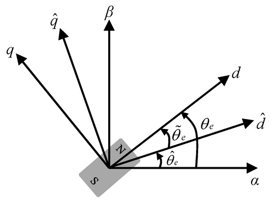
Figure 1.
Relationship between coordinate systems.
Then, the relationship is estimated in the axial coordinate system:
where is the estimated rotor position, is the angular error, and are the high-frequency voltage and current under the axial coordinate system.
After the coordinate transformation in the coefficient matrix, the high-frequency current information is obtained. The simplification of the coordinate transformation matrix with the inductance matrix is:
where is the average inductance and is the differential mode inductance. It can be obtained from Equations (3) and (4):
The voltage injection signal is
where is the amplitude of the signal and is the frequency of the signal.
The value of should not be too large or too small. Too large a value will impact the normal operation of the system. If it is too small, extracting rotor position information during the process of obtaining useful information becomes challenging. should be a comprehensive consideration of the current acquisition. From the sampling theorem, the value of should not exceed half of the maximum frequency. The minimum frequency should be higher than the rotor frequency and the fundamental frequency. This is obtained by substituting (6) into (5) and integrating:
From Equation (7), for IPMSM, due to , are related to in estimated two-phase rotating coordinate systems. When tends to zero, is not zero since it is related to the voltage term. While tends to zero, no torque pulsation occurs. Therefore, the rotor position can be determined by extracting the high-frequency current information under and adjusting this current information to zero. Similarly, if a voltage signal is introduced into the q-axis, the injected signal is:
The corresponding high-frequency current in the axis is
From Equation (9), is not zero when tends to zero. At this time, it will cause torque pulsation and impact the performance. If the high-frequency impedance under the q-axis is smaller than that of the d-axis, injecting a high-frequency voltage signal into the q-axis generates a larger high-frequency current than that injected into the d-axis.
2.1.2. Rotor Position Estimation Method
After obtaining the -axis high-frequency current information under pulse high-frequency voltage injection, the high-frequency current information needs to undergo processing to acquire the rotor information. Firstly, the current information is processed using a bandpass filter (BPF) with a selector frequency of to filter out signals larger than the switching frequency and signals smaller than the fundamental frequency to obtain the high-frequency current component, and then it is sent through a low-pass filter (LPF) and signal processing to acquire the position estimation error information , which is processed as follows:
From (10), when tends to zero, also tends to zero, i.e., tends to the true electrical angle . Therefore, the rotor information can be acquired by designing the phase-locked loop as well as the signal processing process. The position tracking observer uses a second-order phase-locked loop structure in which the loop filter and the voltage-controlled oscillator use a PI controller to obtain the estimated rotational speed and an integrator to acquire the estimated position, respectively, and the framework is shown in Figure 2.
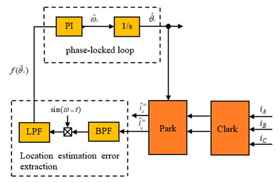
Figure 2.
Rotor position estimation method.
2.2. IPMSM Rotor Position Detection Based on Improved SMO
In this paper, for the rotor information acquisition of motors operating in the middle and high-speed section, the SMO method is used to predict the reverse electromotive force. Specifically, a composite control function is used to acquire the rotor information and to improve the estimation precision.
2.2.1. Design of the Improved SMO
The sliding mode variable framework control system is reconfigured by state reconstruction, using the direct measurements of the original system as inputs to the reconfigured system. The estimated values are obtained after conversion so that the evaluated values converge infinitely to the real output values of the original system [1]. The mathematical model can be represented as:
where are the back electromotive force and the information to be observed by the SMO, which can be stated as:
From Equation (12), the structure of IPMSM salient polarity, magnetic linkage, speed and current determine the back electromotive force. It contains the rotor signal, so the rotor position and speed can be evaluated by obtaining it. Equation (11) is rewritten into the current state equation:
The SMO can be constructed as:
where is the evaluated value of the SMO, and the control function can be indicated as:
where h is the value of the sliding gain and sat is the saturation function. The control function in the traditional SMO in the digital field can achieve a smooth connection of the system and will not lead to vibration problems because of the transformation of the control function. In practice, there is an undesirable state that impacts the system due to the transformation of the control function and the existence of vibration problems. And the control function’s ability to take the saturation function, in the vicinity of the zero point, will be due to the unstable state of the system and will produce high-frequency switching. The larger the value of the slip film gain, the more obvious the jitter problem, which interferes with the robustness of the control system. The saturation function is replaced by a segmented composite function to improve the system vibration problem. The segmented composite function expression is:
where x is the system state error, i.e., the difference between the current observation and the true value, and a is the boundary layer thickness. From Equation (16), the segmented composite function consists of a symbolic function and a power function, which effectively ensures the smooth connection of its internal function, as shown in Figure 3. In the boundary layer near the zero point, i.e., and , the control function is a power function change and is smooth and continuous near the zero point. The saturation characteristics of the symbolic function are used outside the boundary layer to ensure the robustness of the system.

Figure 3.
Segmented composite function properties.
As can be observed from Figure 3, the value of a affects the thickness of the boundary layer, which influences the control effect and the jitter. Near the zero point, compared with the high-frequency oscillations of the conventional SMO, the segmented composite function with the increase of system switching is smoother, and the degree of jitter is weakened, but the control effect is reduced. On the contrary, as the number of system switches decreases, jitter will increase. Therefore, the value of a in the segmented composite function is the key. It is set as a variable with a certain relationship with the rotational speed, which not only guarantees the convergence speed of the system, but also suppresses the vibration to a certain extent [32]. From Equations (13), (14) and (16), the enhanced SMO can be stated as:
The current error state equation for the improved SMO is shown as follows:
Equation (16) is employed to substitute the saturation function in the traditional SMO, which is filtered to obtain the estimation of the back electromotive force, and thus get the rotor information. In this case, the framework of the improved SMO is presented in Figure 4.
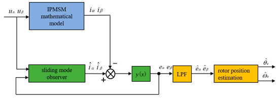
Figure 4.
The structure of the improved SMO.
The Lyapunov function is introduced for system stability determination to determine whether the system can get into the sliding mode surface and stabilize at the equilibrium point:
The conditions for the system to achieve stability are:
From Equations (19) and (20), the stabilization condition is:
Since , and , then Equation (20) holds when .
h should be larger than the component of the back electromotive force on the axis. To ensure that the system attains a stable state, h should be slightly larger. Since h is too large to cause the system to experience jitter vibration, the value of h should not be too large. Otherwise, it will cause the high-frequency signal switching to aggravate the system jitter vibration phenomenon.
2.2.2. Rotor Position Estimation Method
The low-pass filter is employed to remove the high-frequency components of the signal quantity obtained after applying the segmented composite function for the purpose of deriving an estimate of the back electromotive force. When the back electromotive force passes through the low-pass filter, it can introduce a phase delay. It affects the accuracy of the rotor position obtained by the drive control system. Therefore, the obtained rotor position needs to be compensated for:
where is the electrical angular velocity estimated by the SMO, and is the filter cut-off frequency. The compensated rotor position angle obtained with the inverse tangent function is
The rotor speed information is as follows:
2.3. Composite Control Based on Weighted Switching
The sensorless control algorithm of IPMSMs, as mentioned before, usually contains a low-speed control algorithm and a medium-high-speed control algorithm. The low-speed uses high-frequency signal injection, and the medium-high-speed uses the SMO. A transition algorithm is usually needed between these two algorithms to guarantee the smooth operation of the system during the transition. If the transition algorithm is not used to switch directly because the two algorithms’ estimated rotor position information has a deviation, when the offset value is small, the switching process will cause the motor speed and torque fluctuations; when the offset value is large, it will result in the disappearance of torque, which causes the system to shut down seriously. Either one will affect the control system and reduce the performance, so it is necessary to design a switching algorithm to achieve a smooth transition.
The switching is realized through a linear weighting method, where the high-frequency signal injection method is used when the rotational speed is lower than and the SMO method is used when the rotational speed is higher than . When the speed is in between these values, the two methods jointly determine the weights and then jointly determine the output speed and position information in the transition zone. The weight change curve is shown in Figure 5, where, represents the lower speed limitation of the transition interval, and indicates the upper speed limitation of the transition interval.
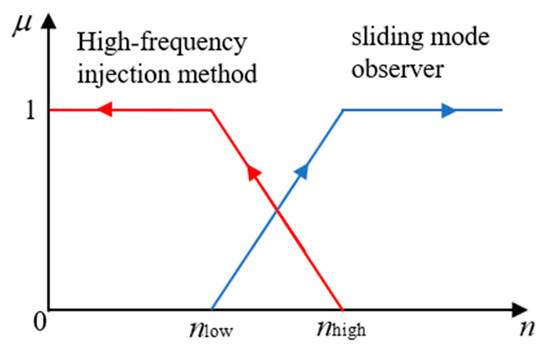
Figure 5.
Weighted switching curve.
The weighting coefficients vary with rotational speed as follows:
Then, the output signal from the switching method is:
where, are the rotor speed and position information evaluated by the high-frequency signal injection, and are the rotor speed and position information estimated by the SMO.
The flow of the switching control algorithm proceeds as follows: when the motor speed is , the information is provided by the high-frequency signal injection method; when the speed is , the information is determined by the high-frequency signal and the SMO. When the motor speed is , the rotor speed and position information are provided by the SMO. Among these conditions, the determination of and is different according to different drive control systems, motor parameters and error requirements. and are based on a simulation to satisfy the requirements of stable operation. As shown in Figure 6, the position errors of the two algorithms are compared under different speed conditions.
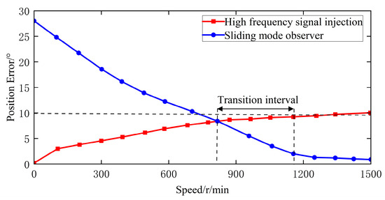
Figure 6.
Comparison of the position error of the two algorithms.
As shown in Figure 6, the two algorithms have a position error threshold of about 10°, within which the IPMSM drive control system is less affected. The selection of needs to be larger than the minimum stable speed that can be obtained by the SMO. The selection of needs to be smaller than the maximum stable speed that can be achieved by the high-frequency signal injection.
3. Sensorless Control Algorithm Simulation
To confirm that the control strategy is effective, simulation models were constructed in Simulink, as described below.
3.1. Sensorless Control Based on High-Frequency Injected Rotor Position Estimation
The sensorless control model is constructed as shown in Figure 7. The current signal in the current sensor is obtained by injecting a high-frequency cosine voltage signal into the d-axis. The current obtained by coordinate transformation is employed to filter out the high-frequency component using a low-pass filter.
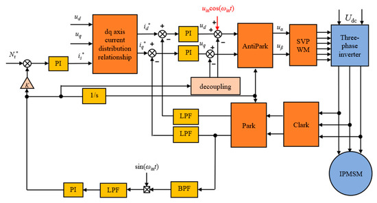
Figure 7.
Sensorless control model diagram.
To study the effect of sensorless control at low speeds, low-speed conditions are set to verify the dynamic performance as well as the robustness of the control system. The specific details of the IPMSM are shown in Table 1, the amplitude of the injected cosine signal is 20 V, and the frequency is 1 kHz. The simulation time is 0.4 s. The reference speed is 100 r/min, and the initial load is 30 Nm. The rotational speed becomes 150 r/min in 0.2 s, and the load becomes 40 Nm in 0.4 s. Figure 8 displays the performance of sensorless control method.

Table 1.
Simulation motor specific details.
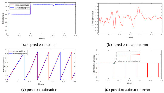
Figure 8.
Performance of control algorithms using high-frequency pulse voltage injection.
From Figure 8a,b, the estimated speed of the sensorless control can follow the response rotational speed. The errors are larger in the startup phase, speed step and load change stage. The estimated speed converges to the response speed after the system is stabilized. The maximum errors in the transient process are about 0.6 r/min and 0.8 r/min, but the speed error is stable at 0.2 r/min after the system is stabilized. From the speed tracking waveform, the dynamic behavior and robustness of the method are good.
Figure 8c,d show the outcomes of electrical angle estimation. From them, the difference between the estimated rotor position and the actual value is relatively small. The rotor position can be evaluated effectively in the speed step and load change stages. However, the position estimation error is larger, and the error is reduced after the system is stabilized. The estimation error is about 0.07 rad. Since the method injects high-frequency signals into the coordinate axis system, the speed and position outputs will inevitably contain a certain degree of jitter. This rotor position detection method remains effective in efficiently estimating the rotor speed and position. It provides a good method for the PMSM drive control system. The rotor position detection method can still effectively estimate the rotor speed, providing rotor information for the IPMSM drive control system.
3.2. Sensorless Control Method Based on an Improved SMO
Figure 9 illustrates the sensorless control model based on the improved SMO. Corresponding simulations and analyses are conducted to confirm the effectiveness of the proposed improved SMO.
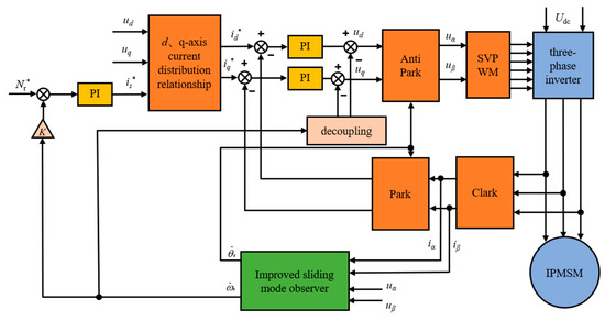
Figure 9.
Sensorless control method diagram.
The performance comparison between the improved SMO and the traditional SMO with the control function as a saturation function verifies that the improved SMO reduces the system jitter to a certain extent. It improves the accuracy of estimation and increases the dynamic property. The simulation time is set at 0.2 s. The speed of the IPMSM is set at 1200 r/min when it is started. The speed is increased at 0.1 s, and it changes to 1800 r/min. The load torque is constant at 20 N·m. The system’s dynamic performance is depicted in Figure 10, Figure 11 and Figure 12.
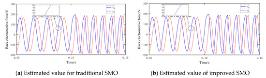
Figure 10.
Estimated value of the back electromotive force by a SMO.
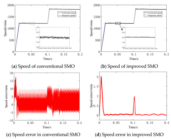
Figure 11.
Speed performance comparison.
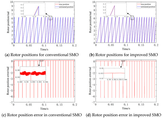
Figure 12.
Rotor position comparison.
Figure 11 provides a comparison of the speed performance between the conventional SMO and the improved SMO. It can be concluded from the local enlarged drawing in Figure 11a that the speed estimated by the conventional SMO contains a large high-frequency jitter error, which results in lower efficiency when the system is running. From the partial zoomed-in plot of Figure 11b, it can be deduced that the high-frequency component of the improved SMO is considerably reduced, resulting in enhanced estimation accuracy. From Figure 11c, it can be obtained that the maximum error reaches 18 r/min in the initial state and 13 r/min in the abrupt shift of the rotational speed. After the speed reaches 1200 r/min, the speed error is about −5~9 r/min. After the speed rises to 1800 r/min, the rotational speed error is about −5~12 r/min. The rotational speed estimation error is large. It contains high-frequency components, causing the system to jitter. From Figure 11d, compared to the traditional SMO speed error, the rotational speed error of the improved method is greatly decreased, and there are fewer high-frequency components. In the initial state of the system and the sudden speed change state, the maximum error is about 2 r/min and 1 r/min. The initial state has a larger error due to the smaller magnitude of the back electromotive force. After smooth operation, the speed error will be about 0.1 r/min. The improved SMO system tracks better.
Figure 12 illustrates the distinction of the electrical angle. From the partial enlargement of Figure 12a, it can be concluded that the rotor position estimated by the traditional SMO exhibits significant high-frequency jitter. The jitter is more obvious in the start-up phase. From Figure 12b, the rotor position estimated by the improved SMO is smoother and the estimation error is significantly reduced. From Figure 12c, the error of the traditional SMO is about 0.05 rad, which contains more high-frequency components, resulting in lower motor efficiency. From Figure 12d, the error of the improved SMO is reduced to 0.015 rad. The observation accuracy is significantly improved. The high-frequency component is smaller. So the improved SMO can realize the position tracking control at medium and high speeds.
3.3. Weighted Switching Algorithm-Based Sensorless Control in the Full Speed Range
The simulation model of the weighted switching algorithm-based sensorless control is shown in Figure 13. Simulations and analyses are conducted to validate the effectiveness of the switching algorithm between low speed and medium speed.
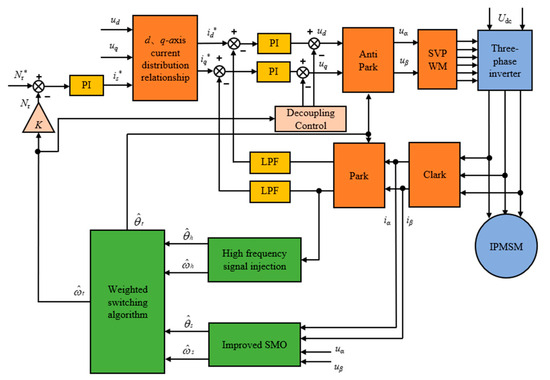
Figure 13.
Weighted switching algorithm.
Based on the rotor speed estimated by the high-frequency signal injection and the SMO, the rotor signal is output according to the switching control method. The stability of the weighted switching algorithm is verified. The control performance results of combining the two control algorithms are depicted in Figure 14. The starting speed is 1200 r/min. The constant load is 20 N-m. The simulation time is 0.1 s.
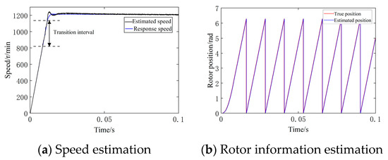
Figure 14.
Rotor information estimation based on weighted switching algorithm.
From Figure 14, although there are some fluctuations in the transition interval, the speed estimation error is minimal. The transition interval is relatively smooth. The tracking drive control system can be realized to respond to the speed. Therefore, the proposed algorithm achieves sensorless control through high-frequency signal injection and a SMO with the switching algorithm in the full-speed range.
4. Experimental Verification
To verify the universality of the fault-tolerant control method under position sensor failure faults, a Speedgoat-based Rapid Control Prototype hardware platform was built, as shown in Figure 15. Experiments were conducted in the low-speed section, high-speed section, and transition interval. The IPMSM model 80AST-M01330LBX (Hangzhou Nazhi Motor Co., Ltd., Hangzhou, China) was selected for testing, which has an interior incremental encoder at the bottom, and the relevant parameters are shown in Table 2.
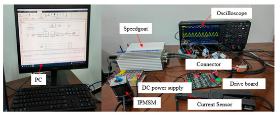
Figure 15.
Speedgoat-based Rapid Control Prototype hardware platform.
Table 2.
Experimental motor basic parameters.
The Rapid Control Prototype platform consists of an IPMSM, a motor driver board, a current clamp, an oscilloscope, a DC power supply, a Speedgoat hardware system and connectors. Different algorithms and working conditions are set by the control software in the PC, which makes it easy to carry out multiple experiments to verify the control algorithms. The Speedgoat hardware system acts as the motor controller in the hardware platform, and the software level between Speedgoat and the PC communicates through the TCP/IPv4 protocol. Their IP addresses are within the same channel, and the hardware connection is achieved through a network cable.
The control objective of this study is to achieve stable operation of the control strategy across the entire speed range through semi-physical simulation experiments, providing support for its application in complex operating conditions. The goal is to attain accurate position and speed estimation for IPMSM throughout the entire speed range. It is anticipated that the steady-state error of speed estimation relative to the target speed will be below 5% at low speeds and below 3% at medium to high speeds.
The above experimental platform was used to complete the experimental verification under steady-state working conditions. The speed conditions were set to 600 r/min and 2000 r/min to validate the performance of the control technology under low-speed and medium-high-speed conditions. As shown in Figure 16 and Figure 17, the experimental waveforms are shown under different speed conditions. The sensor-less control technique can estimate the actual speed and rotor position at low and medium-high speeds, although the estimated value fluctuates greatly compared with the actual value. The estimated speed fluctuates between the actual speed and the target speed, and the estimated rotor position effectively tracks the actual rotor position. The steady-state error of the estimated motor speed relative to the target speed is about 3% at low speeds and about 1% at medium and high speeds. The results of the speed tracking error at this speed condition are shown in Table 3. From the table, the average error of speed estimation is 8.23 r/min and 7.21 r/min at low and medium-high speeds, respectively. The above results confirm the estimation effect of the control technique at low and medium-high speeds.
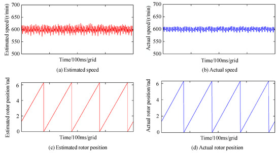
Figure 16.
Control results at a speed of 600 r/min.
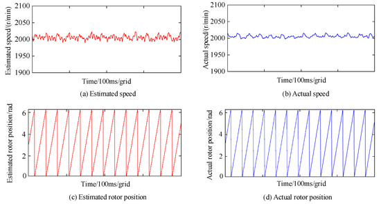
Figure 17.
Control results at a speed of 2000 r/min.
Table 3.
Sensorless control technology speed tracking error.
To verify the smoothness of the switching strategy between low-speed and medium-high speed, the experiment with the algorithms of the sensorless control technology was carried out in the transition interval of speed. The set speed was slowly increased from 600 r/min to 1800 r/min and maintained for 2 s, and then slowly decelerated from 1800 r/min to 600 r/min. As depicted in Figure 18, the experimental waveforms of the estimated speed, the actual speed, the estimated position of the rotor and the actual position of the rotor are shown. The speed increase and speed decrease both took about 3 s, and the speed was stable at 1800 r/min for 2 s. The estimated speed in the speed change curve can effectively track the actual speed and ensure smooth operation. There was no obvious fluctuation, and the overall waveform was relatively smooth, which verifies the effectiveness of the weighted switching algorithm.
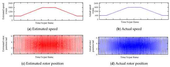
Figure 18.
Dynamic speed with sensorless control technology.
5. Conclusions
In this paper, fault-tolerant control strategies for IPMSM position sensors under the occurrence of faults are investigated as follows:
- (1)
- The IPMSM rotor position detection technology based on high-frequency signal injection is analyzed, and its signal injection strategy and position estimation method are studied. The rotor position detection results in the low-speed section are verified through simulation. The results show that the steady state speed error is about 0.2 r/min, and the steady state position error is about 0.07 rad at low speed.
- (2)
- For rotor position detection in the middle and high-speed sections, an SMO method is used. An improved SMO based on a segmented composite function is proposed, and it has smooth signal estimation and a small error compared with the traditional SMO. The steady-state speed error is improved to 0.1 r/min, and the position error is improved from 0.05 rad to 0.015 rad.
- (3)
- For the problem of smooth switching between the rotor position detection algorithms in the low-speed section and the medium-high-speed section, a linear weighting method is used. The interval is determined through simulation to ensure that the errors of the two algorithms are small in the switching interval. Relatively smooth switching between the two algorithms is achieved.
- (4)
- A rapid control prototype hardware platform based on the Speedgoat controller was built. The experimental platform was used to verify the position sensorless control strategy under different speed conditions. The results show that the position sensorless control strategy can track the speed and rotor position well in the full-speed section.
- (5)
- The simulation models and experiments conducted in this study were carried out under the assumption of constant loads. However, it is well recognized that load variations can significantly impact rotor position estimation in IPMSMs. In future research, we plan to analyze the effects of load changes on rotor position estimation. This will involve conducting experiments with varying load gradients to investigate the influence of different loads on the sensorless control strategy. The aim is to enhance the adaptability of this control algorithm to the complex operating conditions of drive motors. Furthermore, we intend to refine the weighted switching strategy to further improve the smoothness of control strategy transitions. These future steps will contribute to a more comprehensive and robust sensorless control approach for IPMSMs.
Author Contributions
Conceptualization, K.X., J.M. and X.Z.; methodology, J.W. and D.G.; validation, D.M.; formal analysis, J.W. and K.X.; data curation, X.Z.; writing—original draft preparation, J.W. and K.X.; writing—review and editing, J.M.; visualization, D.M.; funding acquisition, X.Z. All authors have read and agreed to the published version of the manuscript.
Funding
This work was funded by the National Key Research and Development Program of China (Grant No. 2020YFB1600604), the Major Science and Technology Project of Shaanxi Province (Grant No. 2020zdzx06-01-01) and the Fundamental Research Funds for the Central Universities (Grant No. 300102223206).
Data Availability Statement
Data are contained within the article.
Conflicts of Interest
The authors declare no conflict of interest.
References
- Zhang, Y.; Qi, R. Flux-Weakening Drive for IPMSM Based on Model Predictive Control. Energies 2022, 15, 2543. [Google Scholar] [CrossRef]
- Li, C.; Zhang, W.; Gao, J.; Huang, S. Permanent Magnet Flux Linkage Analysis and Maximum Torque per Ampere (MTPA) Control of High Saturation IPMSM. Energies 2023, 16, 4717. [Google Scholar] [CrossRef]
- Wang, L.; Ma, J.; Zhao, X.; Li, X. Development of a Typical Urban Driving Cycle for Battery Electric Vehicles Based on Kernel Principal Component Analysis and Random Forest. IEEE Access 2021, 9, 15053–15065. [Google Scholar] [CrossRef]
- Zhang, Y.; Ma, J.; Zhao, X.; Liu, X.; Zhang, K. A Modified Unscented Kalman Filter Combined with Ant Lion Optimization for Vehicle State Estimation. Math. Probl. Eng. 2021, 2021, 8847075. [Google Scholar] [CrossRef]
- Li, X.; Ma, J.; Zhao, X.; Wang, L. Study on Braking Energy Recovery Control Strategy for Four-Axle Battery Electric Heavy-Duty Trucks. Int. J. Energy Res. 2023, 2023, 1868528. [Google Scholar] [CrossRef]
- Li, X.; Ma, J.; Zhao, X.; Wang, L. Research on characteristic parameter selection and attention-GRU-based model for braking intention identification. Proc. Inst. Mech. Eng. Part D-J. Automob. Eng. 2023. [Google Scholar] [CrossRef]
- Wang, M.-S.; Tsai, T.-M. Sliding Mode and Neural Network Control of Sensorless PMSM Controlled System for Power Consumption and Performance Improvement. Energies 2017, 10, 1780. [Google Scholar] [CrossRef]
- Kyslan, K.; Petro, V.; Bober, P.; Slapak, V.; Durovsky, F.; Dybkowski, M.; Hric, M. A Comparative Study and Optimization of Switching Functions for Sliding-Mode Observer in Sensorless Control of PMSM. Energies 2022, 15, 2689. [Google Scholar] [CrossRef]
- Yoo, J.; Lee, J.; Sul, S.-K. Analysis of Instability in Torque Control of Sensorless PMSM Drives in Flux Weakening Region. IEEE Trans. Power Electron. 2021, 36, 10815–10826. [Google Scholar] [CrossRef]
- Liu, S.; Wang, Q.; Zhang, G.; Wang, G.; Xu, D. Online Temperature Identification Strategy for Position Sensorless PMSM Drives with Position Error Adaptive Compensation. IEEE Trans. Power Electron. 2022, 37, 8502–8512. [Google Scholar] [CrossRef]
- Zhu, X.; Zhang, L.; Xiao, X.; Lee, C.H.T.; Que, H. Adjustable-Flux Permanent Magnet Synchronous Motor Sensorless Drive System Based on Parameter-Sensitive Adaptive Online Decoupling Control Strategy. IEEE Trans. Transp. Electrif. 2023, 9, 501–511. [Google Scholar] [CrossRef]
- Shao, Y.; Yu, Y.; Chai, F.; Chen, T. A Two-Degree-of-Freedom Structure-Based Backstepping Observer for DC Error Suppression in Sensorless PMSM Drives. IEEE Trans. Ind. Electron. 2022, 69, 10846–10858. [Google Scholar] [CrossRef]
- Zhu, Q. Complete model-free sliding mode control (CMFSMC). Sci. Rep. 2021, 11, 22565. [Google Scholar] [CrossRef] [PubMed]
- Ebrahimi, N.; Ozgoli, S.; Ramezani, A. Model-free sliding mode control, theory and application. Proc. Inst. Mech. Eng. Part. I J. Syst. Control. Eng. 2018, 232, 1292–1301. [Google Scholar] [CrossRef]
- Wang, G.; Valla, M.; Solsona, J. Position Sensorless Permanent Magnet Synchronous Machine Drives-A Review. IEEE Trans. Ind. Electron. 2020, 67, 5830–5842. [Google Scholar] [CrossRef]
- Wang, Q.; Wang, S.; Chen, C. Review of sensorless control techniques for PMSM drives. IEEJ Trans. Electr. Electron. Eng. 2019, 14, 1543–1552. [Google Scholar] [CrossRef]
- Varatharajan, A.; Pellegrino, G.; Armando, E.; Hinkkanen, M. Sensorless Synchronous Motor Drives: A Review of Flux Observer-Based Position Estimation Schemes Using the Projection Vector Framework. IEEE Trans. Power Electron. 2021, 36, 8171–8180. [Google Scholar] [CrossRef]
- Xu, Y.; Wang, L.; Yuan, W.; Yin, Z. Disturbance rejection speed sensorless control of PMSMs based on full order adaptive observer. J. Power Electron. 2021, 21, 804–814. [Google Scholar] [CrossRef]
- Liu, J.M.; Zhu, Z.Q. Novel Sensorless Control Strategy with Injection of High-Frequency Pulsating Carrier Signal Into Stationary Reference Frame. IEEE Trans. Ind. Appl. 2014, 50, 2574–2583. [Google Scholar] [CrossRef]
- Fu, X.; Xu, Y.; He, H.; Fu, X. Initial Rotor Position Estimation by Detecting Vibration of Permanent Magnet Synchronous Machine. IEEE Trans. Ind. Electron. 2021, 68, 6595–6606. [Google Scholar] [CrossRef]
- Hirakawa, D.; Yamamoto, K.; Shinohara, A. Estimated Position Error Compensation Method Considering Impact of Speed and Load in Permanent Magnet Synchronous Motor Position Sensorless Control Based on High-Frequency Voltage Injection. IEEJ J. Ind. Appl. 2021, 10, 624–631. [Google Scholar] [CrossRef]
- Luo, X.; Tang, Q.; Shen, A.; Zhang, Q. PMSM Sensorless Control by Injecting HF Pulsating Carrier Signal Into Estimated Fixed-Frequency Rotating Reference Frame. IEEE Trans. Ind. Electron. 2016, 63, 2294–2303. [Google Scholar] [CrossRef]
- Sun, X.; Cai, F.; Yang, Z.; Tian, X. Finite Position Control of Interior Permanent Magnet Synchronous Motors at Low Speed. IEEE Trans. Power Electron. 2022, 37, 7729–7738. [Google Scholar] [CrossRef]
- Repecho, V.; Bin Waqar, J.; Biel, D.; Doria-Cerezo, A. Zero Speed Sensorless Scheme for Permanent Magnet Synchronous Machine Under Decoupled Sliding-Mode Control. IEEE Trans. Ind. Electron. 2022, 69, 1288–1297. [Google Scholar] [CrossRef]
- Malekipour, A.; Corne, A.; Garbuio, L.; Granjon, P.; Gerbaud, L. A Closed-Loop PMSM Sensorless Control Based on the Machine Acoustic Noise. IEEE Trans. Ind. Electron. 2023, 70, 9859–9869. [Google Scholar] [CrossRef]
- Narzary, D.; Asthana, P.; Sarkar, M.K.; Choudhary, P. Sensorless Speed Control of Permanent Magnet Synchronous Machine using Higher Order Sliding Mode Functional Observer. In Proceedings of the 2017 2nd IEEE International Conference on Recent Trends in Electronics, Information & Communication Technology (RTEICT), Bangalore, India, 19–20 May 2017; IEEE: New York, NY, USA, 2017; pp. 1390–1395. [Google Scholar]
- Jung, T.-U.; Jang, J.-H.; Park, C.-S. A Back-EMF Estimation Error Compensation Method for Accurate Rotor Position Estimation of Surface Mounted Permanent Magnet Synchronous Motors. Energies 2017, 10, 1160. [Google Scholar] [CrossRef]
- Gayen, P.K. Magnetizing current based improved rotor position and speed estimation of doubly-fed induction generator using model reference adaptive scheme. Measurement 2021, 173, 108602. [Google Scholar] [CrossRef]
- Zhang, Y.; Cheng, X.-F. Sensorless Control of Permanent Magnet Synchronous Motors and EKF Parameter Tuning Research. Math. Probl. Eng. 2016, 2016, 3916231. [Google Scholar] [CrossRef]
- Luo, X.; Zhao, J.; Xiong, Y.; Xu, H.; Chen, H.; Zhang, S. Parameter Identification of Five-Phase Squirrel Cage Induction Motor Based on Extended Kalman Filter. Processes 2022, 10, 1440. [Google Scholar] [CrossRef]
- Rigatos, G.G.; Siano, P. Sensorless Control of Electric Motors with Kalman Filters: Applications to Robotic and Industrial Systems. Int. J. Adv. Robot. Syst. 2011, 8, 62–80. [Google Scholar] [CrossRef]
- Gong, C.; Hu, Y.; Gao, J.; Wang, Y.; Yan, L. An Improved Delay-Suppressed Sliding-Mode Observer for Sensorless Vector-Controlled PMSM. IEEE Trans. Ind. Electron. 2020, 67, 5913–5923. [Google Scholar] [CrossRef]
- Saadaoui, O.; Khlaief, A.; Abassi, M.; Tlili, I.; Chaari, A.; Boussak, M. A New Full-Order Sliding Mode Observer Based Rotor Speed and Stator Resistance Estimation for Sensorless Vector Controlled Pmsm Drives. Asian J. Control 2019, 21, 1318–1327. [Google Scholar] [CrossRef]
- Wang, Y.; Wu, J.; Guo, Z.; Xie, C.; Liu, J.; Jin, X.; Wang, Z. Fuzzy adaptive super-twisting algorithm based sliding-mode observer for sensorless control of permanent magnet synchronous motor. J. Eng.-JOE 2021, 2021, 788–799. [Google Scholar] [CrossRef]
- Tsujii, Y.; Morimoto, S.; Inoue, Y.; Sanada, M. Effect of Inductance Model on Sensorless Control Performance of SynRM with Magnetic Saturation. IEEJ J. Ind. Appl. 2023, 12, 596–602. [Google Scholar] [CrossRef]
Disclaimer/Publisher’s Note: The statements, opinions and data contained in all publications are solely those of the individual author(s) and contributor(s) and not of MDPI and/or the editor(s). MDPI and/or the editor(s) disclaim responsibility for any injury to people or property resulting from any ideas, methods, instructions or products referred to in the content. |
© 2023 by the authors. Licensee MDPI, Basel, Switzerland. This article is an open access article distributed under the terms and conditions of the Creative Commons Attribution (CC BY) license (https://creativecommons.org/licenses/by/4.0/).