Article

Effect of Ripple Control on Induction Motors

1
Department of Ship Electrical Power Engineering, Faculty of Marine Electrical Engineering, Gdynia Maritime University, Morska St. 83, 81-225 Gdynia, Poland
2
Department of Ship Automation, Faculty of Marine Electrical Engineering, Gdynia Maritime University, Morska St. 83, 81-225 Gdynia, Poland
*
Author to whom correspondence should be addressed.
Energies 2023, 16(23), 7831; https://doi.org/10.3390/en16237831
Submission received: 5 September 2023 / Revised: 21 November 2023 / Accepted: 24 November 2023 / Published: 28 November 2023
(This article belongs to the Special Issue Modeling, Control and Diagnosis of Electrical Machines and Devices)

Abstract

:
One method for the remote management of electrical equipment is ripple control (RC), based on the injection of voltage interharmonics into the power network to transmit information. The disadvantage of this method is its negative impact on energy consumers, such as light sources, speakers, and devices counting zero crossings. This study investigates the effect of RC on low-voltage induction motors through the use of experimental and finite element methods. The results show that the provisions concerning RC included in the European Standard EN 50160 Voltage Characteristics of Electricity Supplied by Public Distribution Network are imprecise, failing to protect induction motors against excessive vibration.

1. Introduction

In many countries [1], operators of distribution systems (DSs) use power lines to transmit communication signals. One possible remote management method of DS operation [2] is based on the superimposition of interharmonics on the voltage waveform [1,2,3,4,5,6,7,8,9,10,11]—components of frequency not being an integer multiple of the fundamental frequency. The novelized version of the standard [12] (2019) calls the injected signals “mains communication voltage” (MCV) and specifies the frequency range as 0.1–100 kHz. In the case of interharmonics with a frequency less than 3 kHz, the method is commonly dubbed “ripple control” (RC) [1,2,3,4,5,6,7,8,9,10,11].
The RC signal was originally produced by motor–generator sets, which were later replaced by static frequency converters [9]. The signal is in the form of telegram code [4,9], for example, of duration ~100 s [5] and value 1–5% of the nominal grid voltage [1]. Of note, this percentage can increase because of resonance phenomena in the power system [4,7,8]. The signal is typically injected into a medium-voltage network and transmitted to a low-voltage grid via power transformers [6,9,11]. In the low-voltage network, it is used to manage customers’ electric meters and various energy receivers [1,2,3,4,5,6,7,8,9,10,11]. Furthermore, it can be applied for load peak reduction in the network [6,10]. If the power demand reaches a programmable threshold, some loads, for example, hot water boilers, heat pumps, or swimming pool pumps, can be switched off [6]. In practice, individual receivers can be configured to recognize specific codes [6].
A new challenge for RC is the effective governing of residential photovoltaic systems (PVs) and electric vehicle chargers and batteries [4,5,7,10]. For example, RC allows the use of sun-tracking systems for PVs to adjust the generated power to the actual grid demand [10]. Controlling PVs with RC is much more cost effective than with the Internet [5]. In summary, RC is considered an efficient, remunerative, and inherently cyber-secure method of managing various electrical equipment [4,5].
One drawback of RC is the negative impact on some energy receivers. It is reported to cause light flickers, audible noise from speakers and ceiling fans, and incorrect working of devices counting zero crossings [2,7,9]. Moreover, voltage interharmonics, applied in this method, are considered harmful power quality disturbances (PQDs). Their occurrence results in the poor operation of rotating machines, light sources, transformers, power electronic appliances, and control systems [13,14,15]. Among the various equipment, rotating machines are particularly sensitive to interharmonics (based on [14,15,16,17,18,19,20,21,22,23,24,25]). They cause speed fluctuations, increases in power losses, torque pulsations, and lateral and torsional vibrations, posing a risk of drivetrain damage [14,15,16,17,18,19,20,21,22,23,24]. The most exposed to failure are some medium-voltage equipment, such as large synchronous generators, multi-megawatt drivetrains with synchronous motors, and turbomachinery (based on [15,24]), which is likely the reason the possible interharmonic limit values in the standard [26] are dedicated to non-generation installations.
Interharmonic contamination usually originates from the working of wind power stations and other renewable sources of energy, cycloconverters, various power electronic equipment, and time-varying loads, including those from AC motors driving a pulsating anti-torque [3,24,27,28,29,30]. Especially significant sources of interharmonics are double-frequency conversion systems, like high-voltage DC links and inverters [29,30]. That is, voltage fluctuations across the capacitor in a DC link (or fluctuations of current flowing through the inductance in a DC link) are transmitted to both the AC input and the AC output of the double-conversion system [29,30,31], which may result in high interharmonic contamination [29]. For example, [29] reported various co-occurring voltage interharmonics, with values as high as 1.17%. These interharmonics were caused by the working of high-power inverters.
To achieve appropriate voltage quality, power quality standards specify limited permissible levels of various PQDs. However, the limits generally do not contain interharmonics. In IEEE-519: Standard for Harmonic Control in Electric Power Systems [26], proposals for two alternative limit curves for non-generation installations are discussed. One curve generally limits interharmonic subgroups of frequencies less than 1 kHz to 0.3% and those having frequencies within 1–2.5 kHz to 0.5%. According to the other limit curve, the permissible value of interharmonics of frequencies less than 2.5 kHz is 0.5%. The exceptions are interharmonics of frequencies close to harmonic frequencies, especially the fundamental one. The limit of voltage interharmonics of frequencies of ~50–70 Hz (in a 60 Hz system) should be based on the IEC flickermeter indication. The standard [26] warns that, in some cases, no intentional emission of voltage interharmonics can interfere with RC signals and underlines that “compatibility of voltage interharmonics with ripple control is necessary (…) and requires country-based limits”.
Further, the European Standard EN 50160 Voltage Characteristics of Electricity Supplied by Public Distribution Network [12] contains the following comment: “The level of interharmonics is increasing due to the development of the application of frequency converters and similar control equipment. Levels are under consideration, pending more experience.” Nevertheless, the standard [12] provides permissible values of voltage interharmonics used for the MCV. The highest limit is for the frequency of 0.1–0.4 kHz—according to [12], “for 99% of a day the 3 s mean value of signal voltages shall be less or equal to” 9%. For the higher frequencies of the MCV, the limits are much lower—at 100 kHz, the permissible value is about 1%.
Previous research works [14,15,16,17,18,19,20,21,22,23,25] do not cover induction motors (IMs) under the interharmonic values and frequencies admitted in [12] for the MCV. Many works [17,18,19,20,21,22,25] deal with IMs in cyclic voltage fluctuations, which are considered the superposition of interharmonics and subharmonics (i.e., components of frequency less than the fundamental values) [3,13,22]. Notably, the results of these investigations [17,18,19,20,21,22,25] cannot be directly applied to assessing the effect of RC on IMs. The impact of a single interharmonic tone on IMs was analyzed in [14,15,22,23,25]. For instance, the authors of [25] presented currents and rotational speed fluctuations for interharmonics of frequencies not exceeding 100 Hz. Other works [14,15,22,23] focused on currents, power losses, torque pulsations, vibrations for interharmonic values of 1%, and frequencies below 200 Hz. However, for these interharmonic and frequency values (the lowest frequencies used in RC), a rather moderate vibration was observed [14]. In summary, based on the current state of knowledge, assessing the effect of RC on IMs is not possible.
Therefore, the objectives of this paper were formulated. This work aims to point out that the limits of MCVs included in EN 50160 [12] are too tolerant and do not prevent IMs from malfunctioning. The second aim is to extend the authors’ previous works [14,15,22] and present the investigation results for interharmonic frequencies and values up to 400 Hz and 9%, respectively. The considerations included in this study are limited to low-voltage equipment and non-generation installations.

2. Methodology

The effect of RC on IMs was investigated using numerical and empirical methods. The computations were performed with the two-dimensional finite element method (FEM) for a cage induction motor TSg100L-4B (rated power of 3 kW), referred to as motor1. Its chosen parameters are provided in Table 1. The model of the investigated motor was identified based on measurement results [32,33] and design data. Firstly, an electromagnetic circuit model was worked out using the RMxprt module and motor data, including ratings, the magnetization characteristic of iron, and geometric dimensions. Furthermore, based on the circuit model, a preliminary FEM model was elaborated. The original mesh proposed by the RMxprt module consisted of about 5000 elements, and the air gap was divided into two regions. Finally, some modifications were made to the field model. To improve the solution convergence, the number of finite elements was increased, and the air gap was divided into three regions. The tau-type mesh used for this study consisted of ~22,000 triangle elements—the stator core was divided into ~6200 elements, while the rotor core comprised ~3700 elements. The maximal length of the stator core elements was about 0.68 mm and that of the rotor core elements was ~0.27 mm. For comparison, the inner stator diameter was 94 mm. For the numerical analysis, the MAXWELL-ANSYS environment (ANSYS Electronics Desktop version 2022R2.4, Canonsburg, USA) and a transient-type solver were employed. Of note, some calculation parameters were found on the grounds of the analysis of solution convergence. The impact of vibrations and deformations was omitted during computations. The experimental validation of the field model is included in [14,32,33].
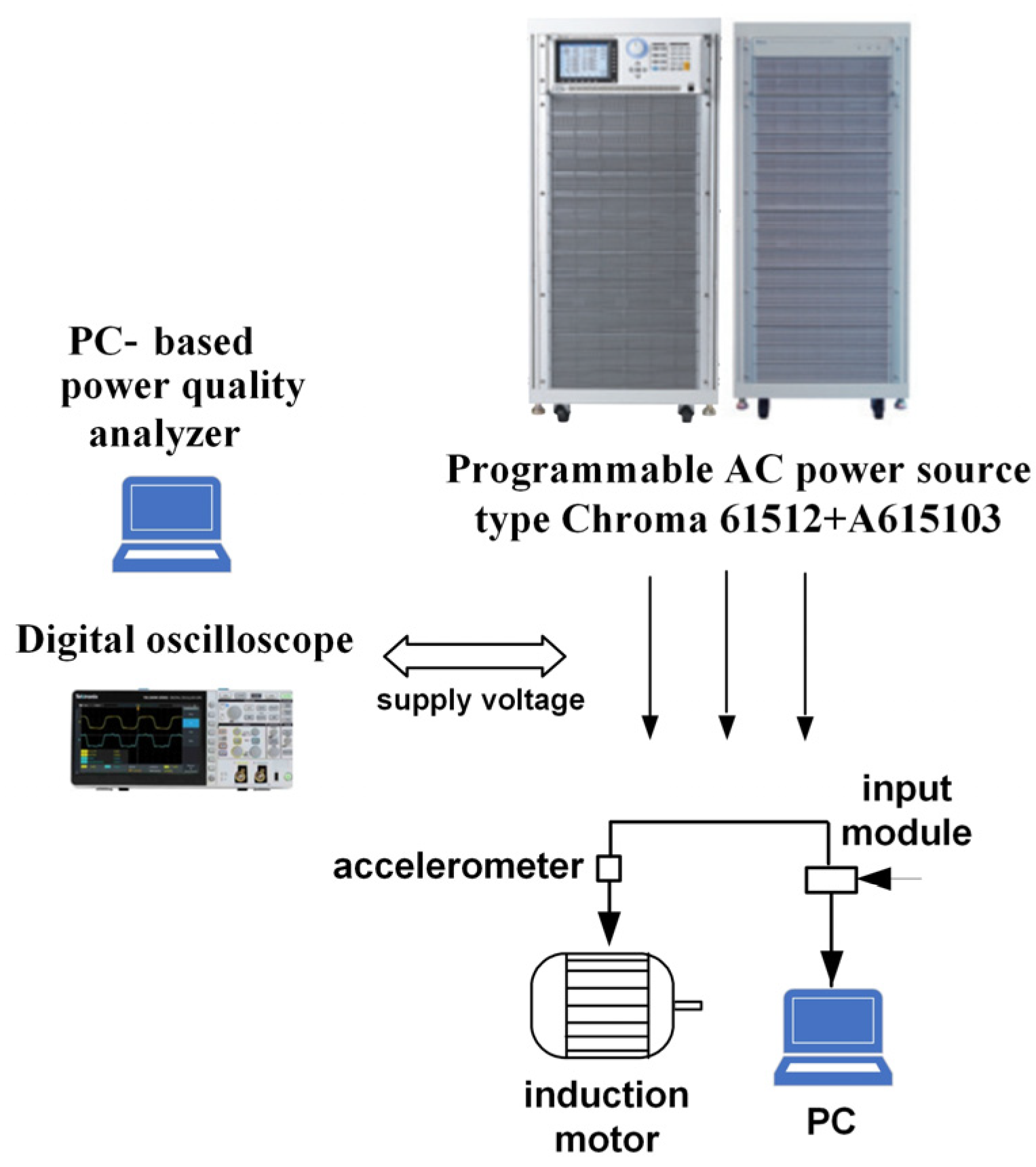
The measurement setup comprised an AC programmable power source, a cage induction motor, a system for vibration measurements, and a computer-based power quality analyzer. The applied power source comprised two units—a Chroma 61512 (master) and a Chroma A615103 (slave) connected in parallel—totaling a rated power of 36 kVA. Additionally, it was equipped with some protection appliances, such as a reverse current protective unit, Chroma A615106. The power source could produce a voltage with programmable PQDs, such as subharmonics and interharmonics (SaIs) of frequencies from 0.01 to 2400 Hz, harmonics, voltage and frequency fluctuations, and phase or amplitude voltage unbalance.
The investigated motor 1LE1003-1BB22-2AA4 (rated power of 4 kW, referred to as motor2) was coupled with an unloaded DC machine (PZMb 54a, working as a generator). The motor2 nameplate parameters are provided in Table 1. Of note, the presence of the DC generator resulted in a small anti-torque (caused by mechanical losses of the generator) and an increase in the moment of inertia of the powertrain (which significantly affects torque pulsations under SaIs [22,33,34]). Additionally, the presence of the coupling may also exert an impact on vibration. According to the authors’ experience (e.g., [15,22]), the vibrations may differ considerably in the cases of an uncoupled motor and a motor coupled with any machine (for instance, with an unloaded DC generator).
For vibration measurement, a Bruel & Kjaer (B&K) system was employed, which included a four-channel data acquisition module (B&K model 3676-B-040), a three-axis magnetically mounted accelerometer (B&K model 4529-B, with a frequency range of 0.3–12,800 Hz, sensitivity of 10 mV/ms−2, maximum shock level peak of 5100 g, and weight of 14.5 g), a calibrator (B&K model 4294), and a computer with installed B&K Connect 2022, version 26.1.0.251 installed. Since the motor casing was made of die-cast aluminum, the accelerometer was attached to dedicated steel stands screwed into the motor (Figure 1). Before each measurement session, the accelerometer was calibrated. After the measurements were taken, the recorded accelerometer indications were filtered through a low-pass filter and recalculated into the broad-band vibration velocity [35,36] using the B&K Connect software. The vibration velocity was determined as per the main provisions of ISO Standard 20816-1 Mechanical vibration—measurement and evaluation of machine vibration—part 1: General guidelines [36].
The voltage and current waveforms were recorded using a digital oscilloscope Tektronix TBS 2000 B equipped with additional measurement transducers. The interharmonic content in the supply voltage and motor current was computed offline, employing fast Fourier transform and software customized by the authors.
A simplified diagram of the measurement setup is presented in Figure 2 (based on [14]).

3. Results

3.1. Preliminary Remarks

During this study, the supply voltage was assumed to contain a single positive-sequence interharmonic of constant value. Numerical computations were performed for the omitted load inertia of the driven appliance (the justification is included in [14,34]). As the highest vibration of IMs caused by SaIs was observed for no load [15], all research results concern this state. Of note, some motors temporarily work with much less output power than rated [37,38] or even no-load conditions, for example, under the standard duty type S6 15% [39]. The torques, currents, and their frequency components are presented in relation to their rated values.

3.2. Currents

The primary source of the excessive vibration of IMs supplied with voltage with SaIs is torque pulsations caused by the flow of current SaIs (based on [15,40]).
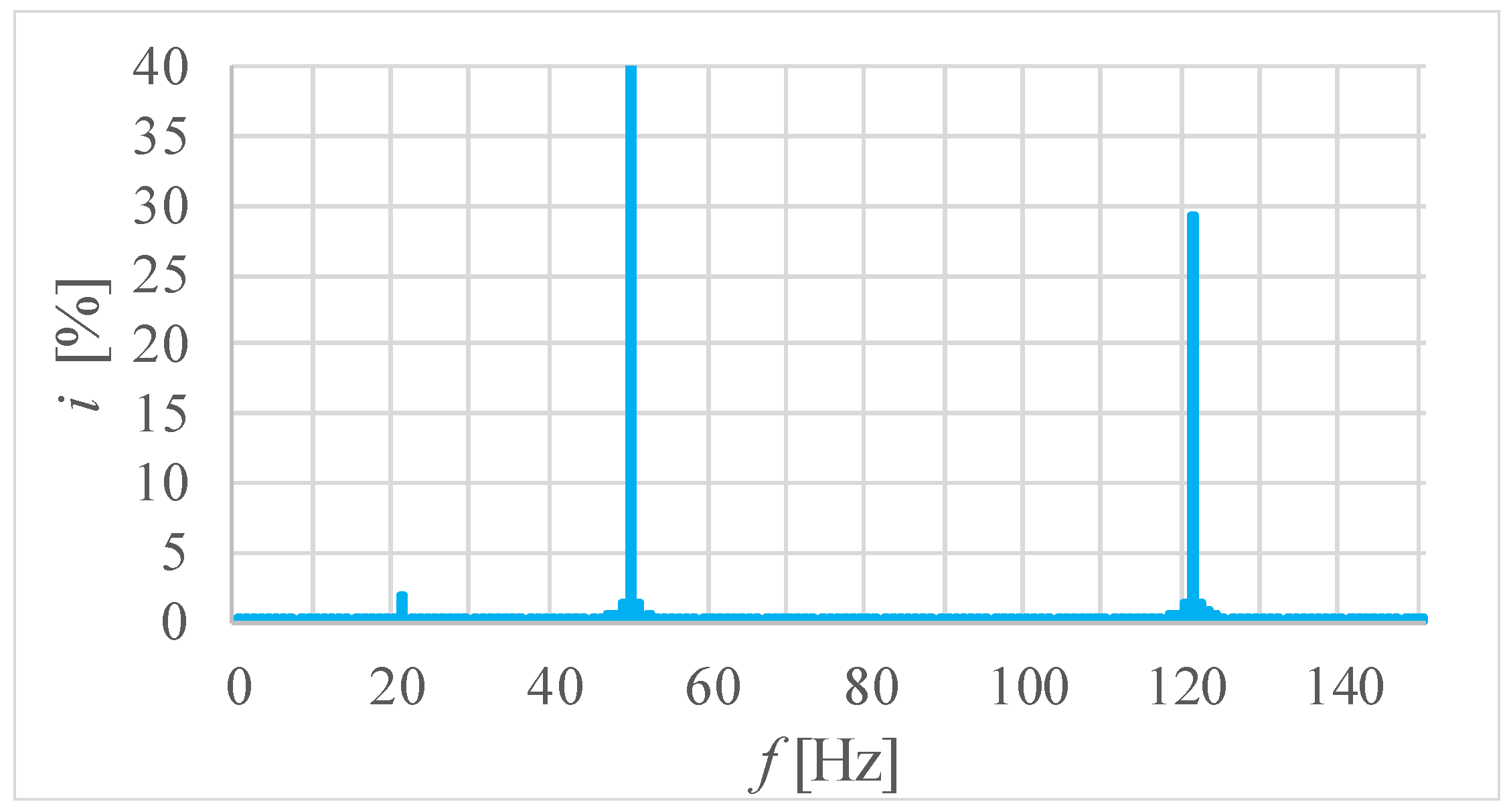
A sample current waveform and its spectrum are shown in Figure 3 and Figure 4, respectively, for motor1, in which the interharmonic frequency fih is 121 Hz and the value uih is 9%. Aside from the fundamental harmonic, the most significant frequency component is the interharmonic frequency fih = 121 Hz and value of 29.3% of the rated current Irat. Additionally, the spectrum contains subharmonic components, which may produce voltage subharmonics in a power system. Notably, subharmonics of apparently inconsiderable values may harm the rotating machinery and transformers [13,15].
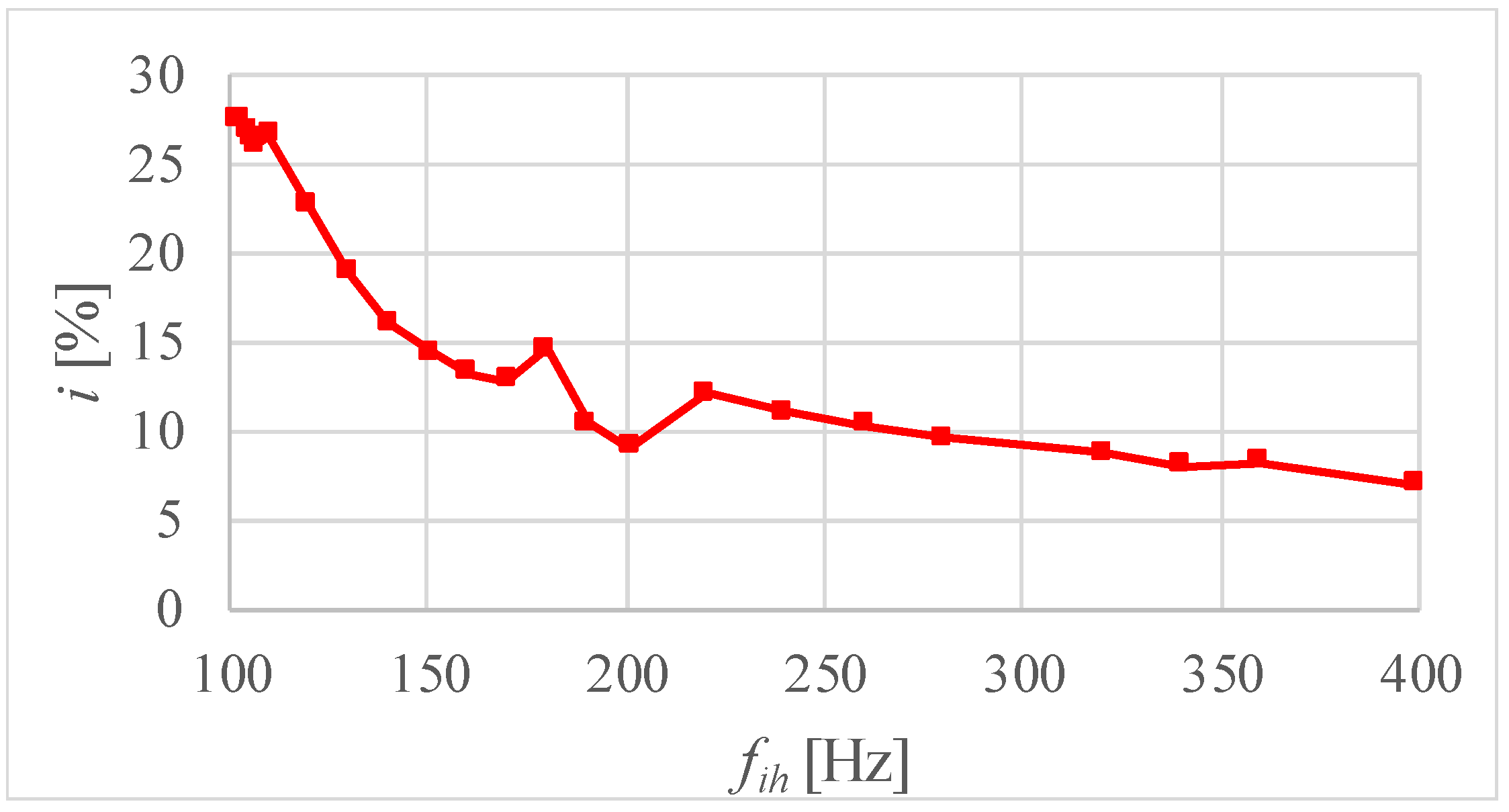
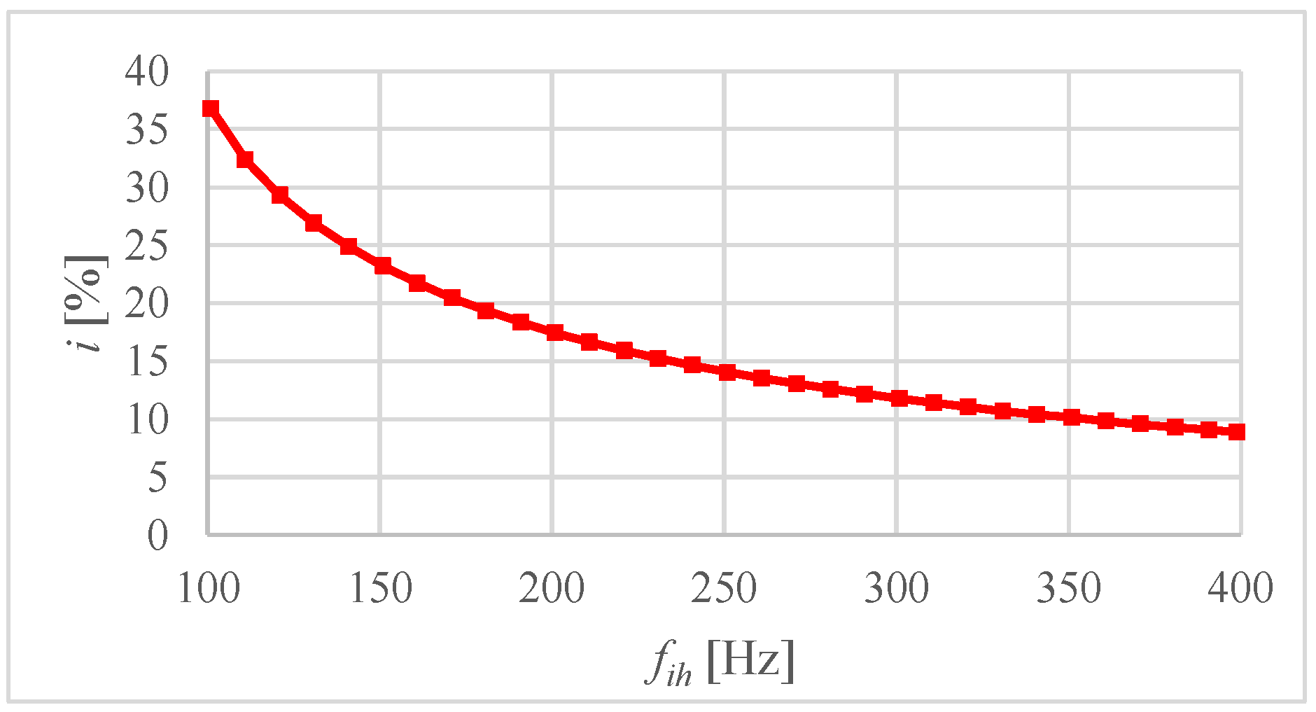
The measured characteristic of the current interharmonics versus their frequency is provided in Figure 5 for motor2. The characteristic generally decreased but with small local extrema around the frequency fih ≈ 200 Hz, which may be due to resonance phenomena. The authors also carried out numerical investigations for motor1. Likewise, the computed characteristic of current subharmonics (Figure 6) decreased as the frequency fih increased. The general shape of the characteristics is due to the leakage inductance suppressing current interharmonics more significantly for the higher frequency fih.
The analogical characteristics for the same motors at uih = 1% and frequencies of 50 to 100 Hz (motor1) or 200 Hz (motor2) are given in [14]. The main difference between these characteristics and those in Figure 5 and Figure 6 is the global maxima below 100 Hz caused by the rigid-body resonance of the rotating mass.
In summary, for the investigated motors, the characteristics of current interharmonics generally decreased as the frequency fih increased and did not show global maxima in the considered frequency range.

3.3. Electromagnetic Torque Pulsations

Positive-sequence interharmonics cause a pulsating torque component (PTC) of the frequency fp based on [25] the following:
f p = f i h f 1
where f1 is the fundamental frequency.
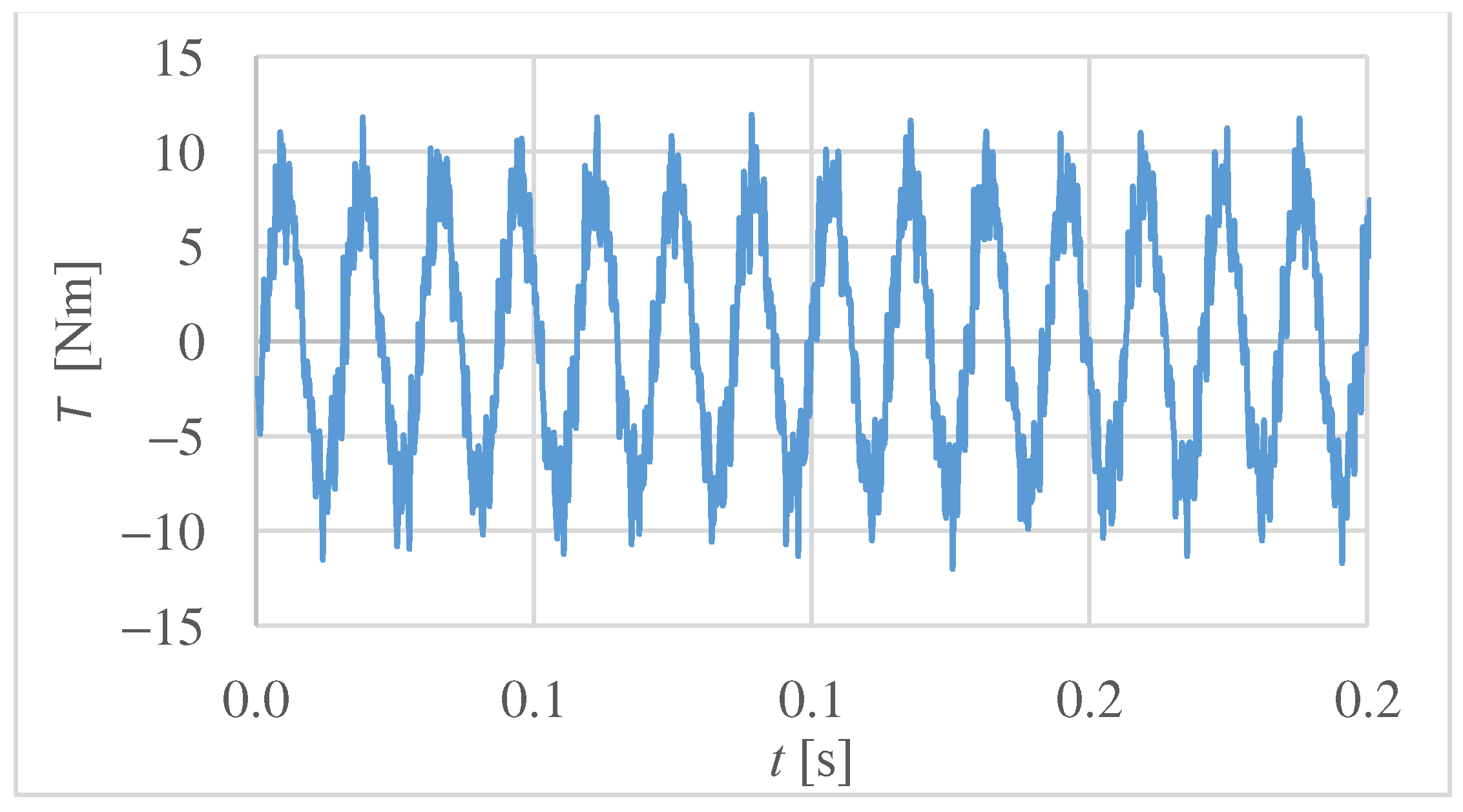
Figure 7 and Figure 8 show the computed waveform and its spectrum of the electromagnetic torque for motor1, respectively, supplied with a voltage having an interharmonic frequency fih of 121 Hz and a value uih of 9%. The PTC frequency fp = 71 Hz reached 39.7% of rated torque (Trat). In contrast, the constant component (resulting from the first current harmonic) was approximately 1% of Trat, typical for low-power, four-pole IMs under no load.
Figure 9 presents the PTCs of the frequency fp versus the interharmonic frequency fih. For fih = 101 Hz, the PTC value was approximately four times that for fih = 399 Hz and reached ~50% of Trat. Of note, this value is close to the maximal PTC observed for IMs supplied with voltage containing a single subharmonic value ush = 1% [21], resulting in extraordinarily high vibration [15,22].
In some cases, the interharmonic value of 9% disturbed the starting process of motor2 (starting with the reduced supply voltage). This issue will be deeply analyzed in a separate paper.
In summary, RC caused a significant PTC, leading to excessive IM vibrations.

3.4. Vibration

For the assessment of vibration severity, the recommendations included in the standards [35,36] were employed. They specify four evaluation zones, denoted as Zone A, Zone B, Zone C, and Zone D. Zone C corresponds to vibrations admitted for a limited time, while the vibrations within Zone D “are normally considered to be of sufficient severity to cause damage to the machine”. As the threshold values of each evaluation zone are not univocally specified in the current standard [36], they were assumed based on its former version [35]. Per [35], for low-power electric motors, a broad-band vibration velocity [35,36] between 1.8 and 4.5 mm/s corresponds to Zone C, and a vibration velocity greater than 4.5 mm/s corresponds to Zone D.
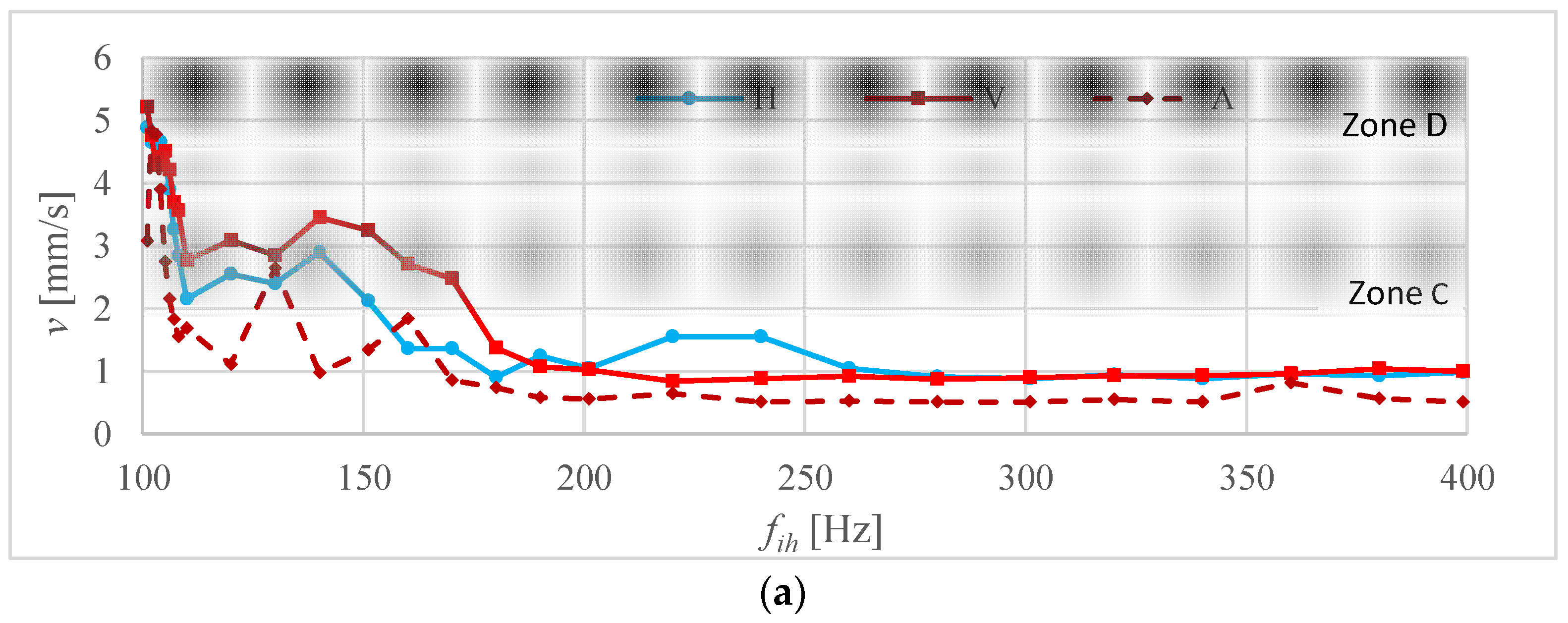
Figure 10 presents the characteristics of the broad-band vibration velocity versus the frequency of the voltage interharmonics for uih = 9% and motor2. The measured vibration velocity reached 5.025 mm/s, exceeding the boundaries of Zone D for the frequency fih ≤ 105 Hz. Furthermore, for a frequency fih of 106 to 170 Hz, the vibration velocity fell into Zone C. Of note, the most severe vibration occurred for frequencies fih corresponding to the highest PTCs (see the previous subsection). Nevertheless, “the magnitude of the … vibration directly depends on the mechanical behavior of the motor structure and the possibility of a resonance condition … on the structure of an entire unit or on the motor components, such as a stator core or frame” [40]. Consequently, for other drivetrains, the highest vibration may appear for other frequency fih values. Furthermore, the shape of the characteristic under consideration can be explained by both the behavior of the mechanical structure and the effect of leakage inductance (see Section 3.2 and Section 3.3).
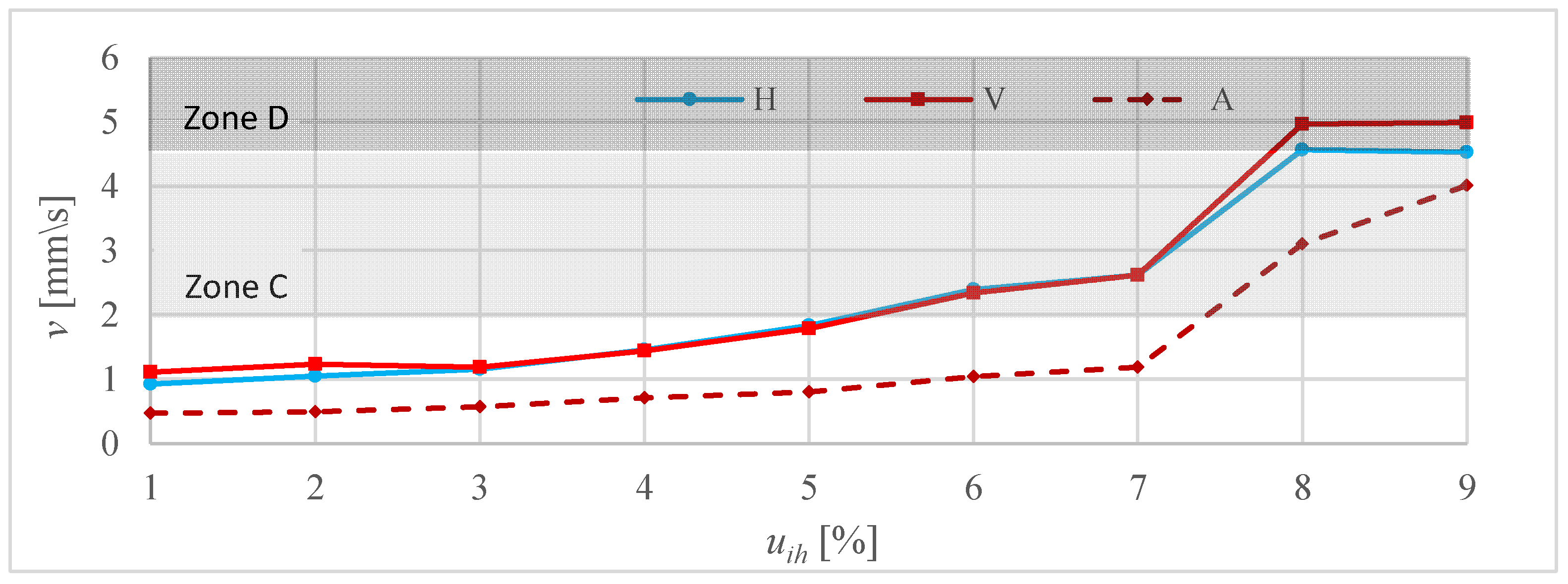
Figure 11 shows the characteristics of the broad-band vibration velocity versus the interharmonic value uih for the frequency fih = 101 Hz and motor2. The plots show significant non-linearity, probably due to the coupling reaction. For ush ≤ 7%, the vibration velocity gradually increased to 2.62 mm/s, exceeding the threshold value of Zone C for ush ≈ 5%. In turn, between uih = 7% and uih = 8%, it rapidly increased to 4.97 mm/s and fell into Zone D.
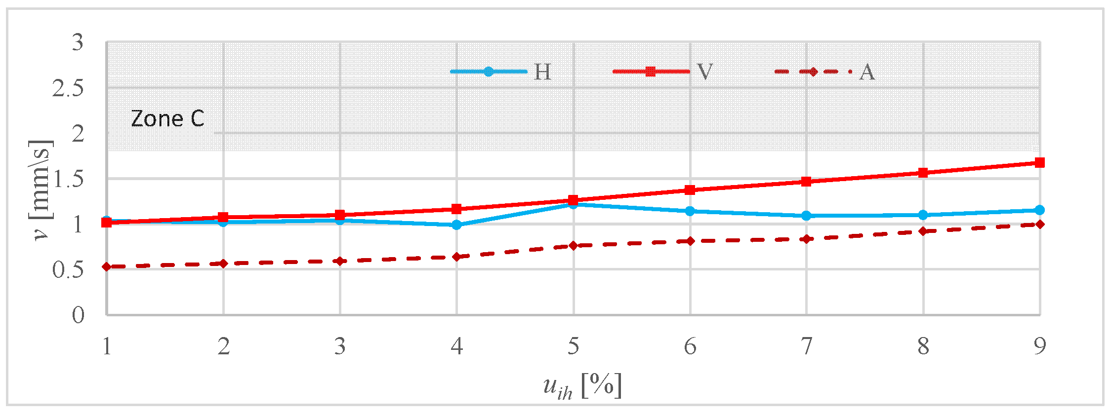
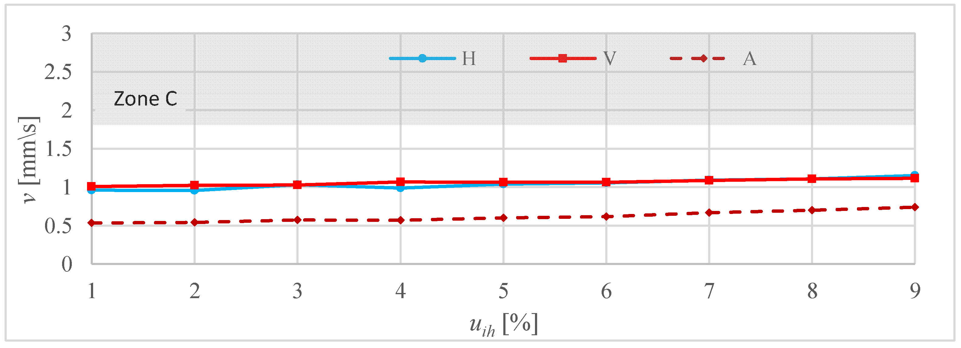
The characteristics presented in Figure 11 were measured using the frequency fih corresponding to the highest vibration velocity (see Figure 10). Contrastingly, Figure 12 and Figure 13 present analogical characteristics for frequencies at which motor2 showed comparatively low vibration. The appropriate experimental investigations were performed for exemplary RC signal frequencies [1,5,11]: fih = 175 Hz (Figure 12) and 208.3 Hz (Figure 13). The maximal vibration velocity did not exceed 1.672 mm/s and fell into Zone B.
In summary, the presented results of investigations indicate that the application of MCVs at the values permitted in the standard [12] may result in IM failures due to excessive vibration.

4. Discussion

A dynamic growth in the number of PV installations and electric cars presents a new challenge for RC. The distribution network is expected to be increasingly contaminated with RC signals, which should be considered as a specific case of voltage waveform distortions. One receiver especially susceptible to voltage waveform distortions (including voltage harmonics and SaIs) is an induction motor. Voltage waveform distortions cause various harmful phenomena, such as an increase in power losses, overheating, a local saturation of the magnetic circuit, torque ripples, and excessive lateral and torsional vibration [3,13,14,15,17,18,19,20,21,22,23,24,25,31,32,33,34,40,41,42], resulting even in powertrain destruction [31].
To prevent energy receivers from malfunctioning, power quality standards impose limitations on various PQDs. Many European countries apply the standard EN 50160 [12], which specifies the limits of RC signals. According to [12], within the frequency range of 0.1–0.4 kHz, “for 99% of a day the 3 s mean value of signal voltages shall be less or equal to” 9%. In practice, the standard does not limit the value of RC signals whose total duration is less than 1% of the day; in practice, any signal values can be found acceptable in light of [12]. Additionally, the 9% limit in [12] is inappropriate. Voltage interharmonics within this limit cause significant torque pulsations, leading to excessive vibrations. For the investigated motors, their levels fell into evaluation Zone D [35,36], in which they “are normally considered to be of sufficient severity to cause damage to the machine” [35,36].
Currently, only the practice used by DS operators protects IMs from destructive vibration, in which the value of RC signals is usually in the range of 1–5% [1], much less than that permitted by [12]. Of note, the value of RC signals can be significantly amplified because of resonance phenomena [4,7,8], even by a factor of three [8]. Such resonances in a power system were observed at frequencies of 1 kHz [4,8]. At the same time, the vibration of motor2 fell into Zone D for the interharmonic frequency fih ≤ 105 Hz and the value uih ≥ 8%. In practice, such an RC signal is rather unlikely. Nevertheless, these standards should enable the electrical equipment to operate reliably and durably rather than the practice used by DS operators.
Furthermore, the PTC frequency may correspond to the natural torsional frequency of the elastic-body mode [14]. In drivetrains with IMs, the elastic-mode resonance [16,24,31,43,44] may lead to the amplification of PTCs by a factor exceeding 100 [31] and, consequently, a coupling or shaft failure [31,43,44]. Notably, the resonance may cause drivetrain destruction after a comparatively short time, for example, during repetitive starts [43]. The effect of the elastic-mode resonance on IMs will be the subject of future investigations.
Given the above considerations, the provisions in question [12] are unacceptable. They do not protect IMs from the potentially harmful impact of RC, especially with lateral and torsional vibration. Revising the standard [12] requires in-depth investigations of the undesirable phenomena caused by RC.

5. Conclusions

The provisions concerning RC laid in EN 50160 [12] are imprecise and too tolerant. According to [12], any level of RC signals can be considered acceptable, provided that their total duration is less than 1% of the day. For RC signals of longer total durations, the maximal permitted value is as high as 9%. This research shows that, even for interharmonics less than the limit, IM vibration may fall within evaluation Zone D, risking machine damage [35,36]. Presently, only practices used by DS operators prevent IMs from excessive vibration. The standard [12] should be modified taking into account the impact of RC on energy consumers, the real values of RC signals injected into DSs [1], a possible magnification of the signal for some frequencies due to resonance phenomena [4,7,8], and the possible interference of RC signals with voltage interharmonics occurring in the power system.

Author Contributions

Conceptualization, P.G., M.P. and D.H.; methodology, M.P., D.H. and P.J.; formal analysis, M.P., A.M. and D.H.; investigation, M.P., A.M. and D.H.; writing—original draft preparation, P.G.; supervision, P.G. All authors have read and agreed to the published version of the manuscript.

Funding

This project is financially supported under the framework of a program of the Ministry of Science and Higher Education (Poland) as “Regional Excellence Initiative” in the years 2019–2023, project number 006/RID/2018/19, amount of funding PLN 11 870 000.

Data Availability Statement

Data are contained within the article.

Conflicts of Interest

The authors declare no conflict of interest. The funders had no role in the design of this study; in the collection, analyses, or interpretation of data; in the writing of the manuscript; or in the decision to publish the results.

References

  1. Garma, T.; Šesnić, S. Measurement and modeling of the propagation of the ripple control signal through the distribution network. Int. J. Electr. Power Energy Syst. 2014, 63, 674–680. [Google Scholar] [CrossRef]
  2. Battacharyya, S.; Cobben, S.; Toonen, J. Impacts of ripple control signals at low voltage customer’s installations. In Proceedings of the 22nd International Conference on Electricity Distribution, Stockholm, Sweden, 10–13 June 2013. [Google Scholar]
  3. Bollen, M.H.J.; Gu, I.Y.H. Origin of power quality variations. In Signal Processing of Power Quality Disturbances; Wiley: New York, NY, USA, 2006; pp. 41–162. [Google Scholar]
  4. Boutsiadis, E.; Tsiamitros, D.; Stimoniaris, D. Ripple signaling control for ancillary services in distribution networks. Turk J. Electr. Power Energy Syst. 2022, 2, 31–45. [Google Scholar] [CrossRef]
  5. Boutsiadis, E.; Tsiamitros, D.; Stimoniaris, D. Distributed generation control via ripple signaling for establishment of ancillary services in distribution networks. In Proceedings of the 2021 13th International Conference on Electrical and Electronics Engineering (ELECO), Bursa, Turkey, 25–27 November 2021; pp. 18–23. [Google Scholar]
  6. Dzung, D.; Berganza, I.; Sendin, A. Evolution of powerline communications for smart distribution: From ripple control to OFDM. In Proceedings of the 2011 IEEE International Symposium on Power Line Communications and Its Applications, Udine, Italy, 3–6 April 2011; pp. 474–478. [Google Scholar]
  7. Muttaqi, K.M.; Rahman, O.; Sutanto, D.; Lipu, M.H.; Abdolrasol, M.G.; Hannan, M.A. High-frequency ripple injection signals for the effective utilization of residential EV storage in future power grids with rooftop PV system. IEEE Trans. Ind. Appl. 2022, 58, 6655–6665. [Google Scholar] [CrossRef]
  8. Perera, B.S.P.; Nguyen, K.; Gosbell, V.J.; Browne, N.; Elphick, S.; Stones, J. Ripple signal amplification in distribution systems: A case study. In Proceedings of the 10th International Conference on Harmonics and Quality of Power, Rio de Janeiro, Brazil, 6–9 October 2002; Volume 1, pp. 93–98. [Google Scholar]
  9. Rahman, O.; Elphick, S.; Muttaqi, K.M.; David, J. Investigation of LED lighting performance in the presence of ripple injection load control signals. IEEE Trans. Ind. Appl. 2019, 55, 5436–5444. [Google Scholar] [CrossRef]
  10. Tsiakalos, A.; Tsiamitros, D.; Tsiakalos, A.; Stimoniaris, D.; Ozdemir, A.; Roumeliotis, M.; Asimopoulos, N. Development of an innovative grid ancillary service for PV installations: Methodology, communication issues and experimental results. Sustain. Energy Technol. Assess. 2021, 44, 101081. [Google Scholar] [CrossRef]
  11. Yang, Y.; Dennetière, S. Modeling of the behavior of power electronic equipment to grid ripple control signal. Electr. Power Syst. Res. 2009, 79, 443–448. [Google Scholar] [CrossRef]
  12. EN Standard 50160, 2010/A2:2019; Voltage Characteristics of Electricity Supplied by Public Distribution Network. CELENEC: Brussels, Belgium, 2019.
  13. Gallo, D.; Landi, C.; Langella, R.A.; Testa, A. Limits for low frequency interharmonic voltages: Can they be based on the flickermeter use. In Proceedings of the 2005 IEEE Russia Power Tech, St. Petersburg, Russia, 27–30 June 2005; pp. 1–7. [Google Scholar]
  14. Gnaciński, P.; Hallmann, D.; Klimczak, P.; Muc, A.; Pepliński, M. Effects of voltage interharmonics on cage induction motors. Energies 2021, 14, 1218. [Google Scholar] [CrossRef]
  15. Gnacinski, P.; Peplinski, M.; Murawski, L.; Szelezinski, A. Vibration of induction machine supplied with voltage containing subharmonics and interharmonics. IEEE Trans. Energy Convers. 2019, 34, 1928–1937. [Google Scholar] [CrossRef]
  16. Bongini, L.; Mastromauro, R.A. Subsynchronous torsional interactions and start-up issues in oil & gas plants: A real case study. In Proceedings of the AEIT International Annual Conference (AEIT), Firenze, Italy, 18–20 September 2019; pp. 1–6. [Google Scholar]
  17. Ghaseminezhad, M.; Doroudi, A.; Hosseinian, S.H.; Jalilian, A. Analysis of voltage fluctuation impact on induction motors by an innovative equivalent circuit considering the speed changes. IET Gener. Transm. Distrib. 2017, 11, 512–519. [Google Scholar] [CrossRef]
  18. Ghaseminezhad, M.; Doroudi, A.; Hosseinian, S.H.; Jalilian, A. An investigation of induction motor saturation under voltage fluctuation conditions. J. Magn. 2017, 22, 306–314. [Google Scholar] [CrossRef]
  19. Ghaseminezhad, M.; Doroudi, A.; Hosseinian, S.H.; Jalilian, A. Analytical field study on induction motors under fluctuated voltages. Iran. J. Electr. Electron. Eng. 2021, 17, 1620. [Google Scholar]
  20. Ghaseminezhad, M.; Doroudi, A.; Hosseinian, S.H.; Jalilian, A. Investigation of increased ohmic and core losses in induction motors under voltage fluctuation conditions. Iran. J. Sci. Technol. Trans. Electr. Eng. 2018, 43, 1–10. [Google Scholar] [CrossRef]
  21. Ghaseminezhad, M.; Doroudi, A.; Hosseinian, S.H.; Jalilian, A. High torque and excessive vibration on the induction motors under special voltage fluctuation conditions. COMPEL—Int. J. Comput. Math. Electr. Electron. Eng. 2021, 40, 822–836. [Google Scholar] [CrossRef]
  22. Gnaciński, P.; Hallmann, D.; Muc, A.; Klimczak, P.; Pepliński, M. Induction motor supplied with voltage containing symmetrical subharmonics and interharmonics. Energies 2022, 15, 7712. [Google Scholar] [CrossRef]
  23. Gnaciński, P.; Pepliński, M.; Hallmann, D. Currents and Power Losses of Induction Machine Under Voltage Interharmonics. In Proceedings of the 21st European Conference on Power Electronics and Applications (EPE ’19 ECCE Europe), Genova, Italy, 3–5 September 2019. [Google Scholar]
  24. Schramm, S.; Sihler, C.; Song-Manguelle, J.; Rotondo, P. Damping torsional interharmonic effects of large drives. IEEE Trans. Power Electron. 2010, 25, 1090–1098. [Google Scholar] [CrossRef]
  25. Tennakoon, S.; Perera, S.; Robinson, D. Flicker attenuation—Part I: Response of three-phase induction motors to regular voltage fluctuations. IEEE Trans. Power Deliv. 2008, 23, 1207–1214. [Google Scholar] [CrossRef]
  26. IEEE Standard 519-2022; IEEE Recommended Practice and Requirements for Harmonic Control in Electric Power Systems. IEEE: New York, NY, USA, 2022.
  27. Arkkio, A.; Cederström, S.; Awan, H.A.A.; Saarakkala, S.E.; Holopainen, T.P. Additional losses of electrical machines under torsional vibration. IEEE Trans. Energy Convers. 2018, 33, 245–251. [Google Scholar] [CrossRef]
  28. Avdeev, B.A.; Vyngra, A.V.; Chernyi, S.G.; Zhilenkov, A.A.; Sokolov, S.S. Evaluation and procedure for estimation of interharmonics on the example of non-sinusoidal current of an induction motor with variable periodic load. IEEE Access 2021, 9, 158412–158419. [Google Scholar] [CrossRef]
  29. Nassif, A.B. Assessing the impact of harmonics and interharmonics of top and mudpump variable frequency drives in drilling rigs. IEEE Trans. Ind. Appl. 2019, 55, 5574–5583. [Google Scholar] [CrossRef]
  30. Testa, A.; Akram, M.F.; Burch, R.; Carpinelli, G.; Chang, G.; Dinavahi, V.; Hatziadoniu, C.; Grady, W.M.; Gunther, E.; Halpin, M.; et al. Interharmonics: Theory and modeling. IEEE Trans. Power Deliv. 2007, 22, 2335–2348. [Google Scholar] [CrossRef]
  31. Tripp, H.; Kim, D.; Whitney, R. A Comprehensive Cause Analysis of a Coupling Failure Induced by Torsional Oscillations in a Variable Speed Motor; Texas A&M University, Turbomachinery Laboratories: College Station, TX, USA, 1993; pp. 17–24. [Google Scholar]
  32. Gnaciński, P.; Pepliński, M.; Hallmann, D.; Jankowski, P. Induction cage machine thermal transients under lowered voltage quality. IET Electr. Power Appl. 2019, 13, 479–486. [Google Scholar] [CrossRef]
  33. Gnaciński, P.; Pepliński, M.; Hallmann, D.; Jankowski, P. The effects of voltage subharmonics on cage induction machine. Int. J. Electr. Power Energy Syst. 2019, 111, 125–131. [Google Scholar] [CrossRef]
  34. Gnaciński, P.; Klimczak, P. High-Power induction motors supplied with voltage containing subharmonics. Energies 2020, 13, 5894. [Google Scholar] [CrossRef]
  35. ISO Standard 10816-1; Mechanical Vibration—Evaluation of Machine Vibration by Measurements on Non-Rotating Parts—Part 1: General guidelines. ISO: Genova, Switzerland, 1995.
  36. ISO Standard 20816-1; Mechanical Vibration—Measurement and Evaluation of Machine Vibration—Part 1: General Guidelines. ISO: Genova, Switzerland, 2016.
  37. Singh, R.R.; Raj, C.T.; Palka, R.; Indragandhi, V.; Wardach, M.; Paplicki, P. Energy optimal intelligent switching mechanism for induction motors with time varying load. In Proceedings of the IOP Conference Series: Materials Science and Engineering, Chennai, India, 9 June 2020; p. 906. [Google Scholar]
  38. Singh, R.R.; Chelliah, T.R. Enforcement of cost-effective energy conservation on single-fed asynchronous machine using a novel switching strategy. Energy 2017, 126, 179–191. [Google Scholar] [CrossRef]
  39. IEC Standard 60034-1; Rotating Electrical Machines. Part 1: Rating and Performance. IEC: Genova, Switzerland, 2004.
  40. Tsypkin, M. The origin of the electromagnetic vibration of induction motors operating in modern industry: Practical experience—Analysis and diagnostics. IEEE Trans. Ind. Appl. 2017, 53, 1669–1676. [Google Scholar] [CrossRef]
  41. Gonzalez-Abreu, A.D.; Osornio-Rios, R.A.; Jaen-Cuellar, A.Y.; Delgado-Prieto, M.; Antonino-Daviu, J.A.; Karlis, A. Advances in power quality analysis techniques for electrical machines and drives: A review. Energies 2022, 15, 1909. [Google Scholar] [CrossRef]
  42. Sieklucki, G.; Sobieraj, S.; Gromba, J.; Necula, R.E. Analysis and approximation of THD and torque ripple of induction motor for SVPWM control of VSI. Energies 2023, 16, 4628. [Google Scholar] [CrossRef]
  43. Feese, T.; Ryan, M. Torsional Vibration Problem with Motor/ID Fan System Due to PWM Variable Frequency Drive; Texas A&M University, Turbomachinery Laboratories: College Station, TX, USA, 2008. [Google Scholar]
  44. Perez, R.X. Design, Modeling and Reliability in Rotating Machinery; Wiley: Hoboken, NJ, USA, 2022. [Google Scholar]
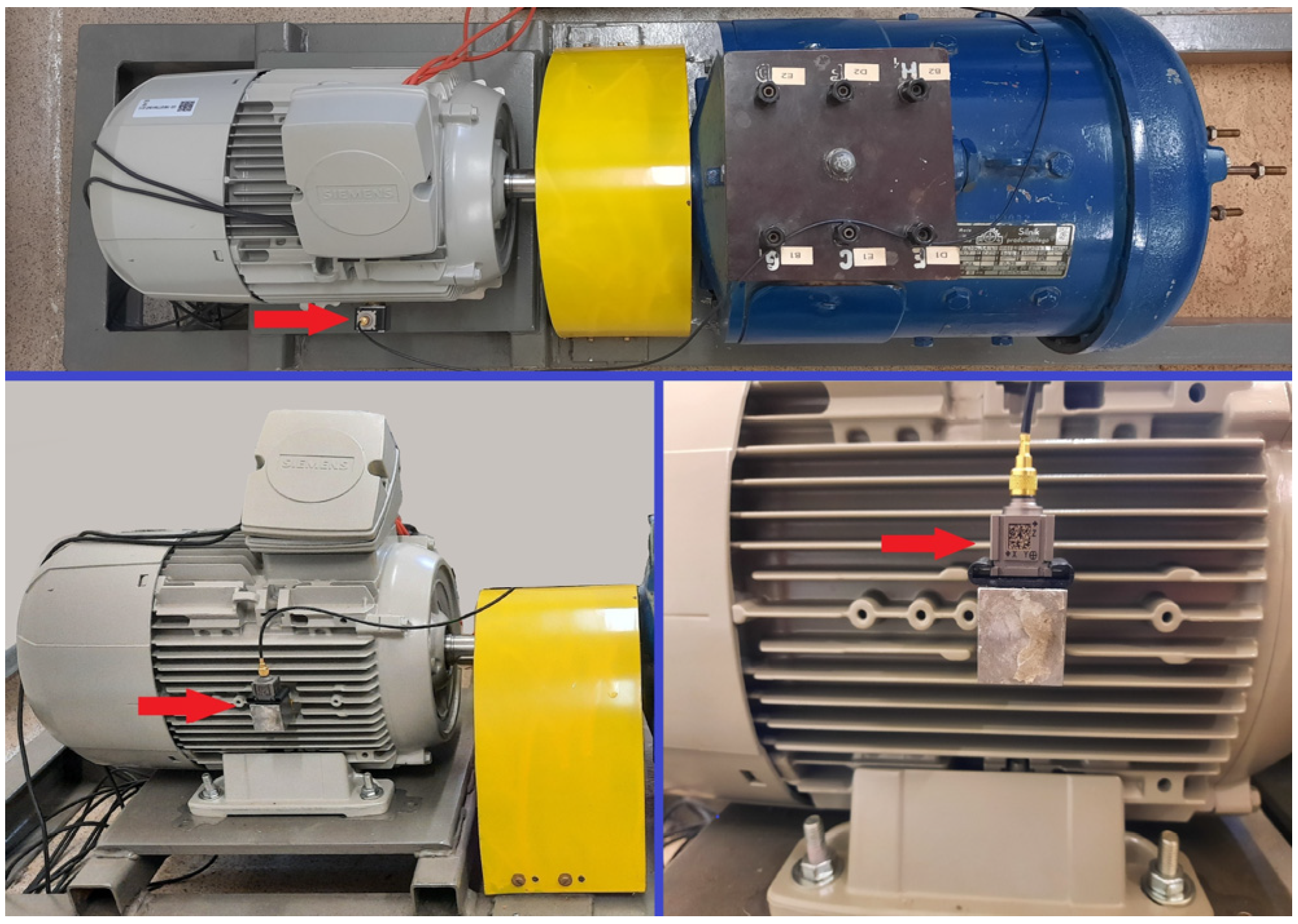
Figure 1. Motor2 and the accelerometer (indicated with the red arrow).
Energies 16 07831 g001
Figure 2. Simplified diagram of the measurement setup.
Energies 16 07831 g002
Figure 3. Measured current waveform of motor1 under no load, supplied with voltage containing interharmonics of value uih = 9% and frequency fih = 121 Hz.
Energies 16 07831 g003
Figure 4. Spectrum of the current waveform presented in Figure 3.
Energies 16 07831 g004
Figure 5. Measured current interharmonics versus their frequency for motor2 under no load. Current interharmonics are related to the rated motor current.
Energies 16 07831 g005
Figure 6. Computed current interharmonics versus their frequency for motor1 under no load. Current interharmonics are related to the rated motor current.
Energies 16 07831 g006
Figure 7. Torque waveform of motor1 under no load, supplied with the voltage containing the interharmonic value uih = 9% and frequency of fih = 121 Hz.
Energies 16 07831 g007
Figure 8. Spectrum of the torque waveform presented in Figure 7.
Energies 16 07831 g008
Figure 9. PTC versus the interharmonic frequency fih for uih = 9% and motor1. PTC is rated to the rated motor torque.
Energies 16 07831 g009
Figure 10. Measured broad-band vibration velocity in the horizontal (H), vertical (V), and axial (A) directions versus the voltage interharmonic frequency for motor2 and interharmonic value uih = 9%. Figure (b) is an enlarged fragment of Figure (a).
Energies 16 07831 g010aEnergies 16 07831 g010b
Figure 11. Measured broad-band vibration velocity in the horizontal (H), vertical (V), and axial (A) directions versus the voltage interharmonic value uih for motor2 and interharmonic frequency fih = 101 Hz.
Energies 16 07831 g011
Figure 12. Measured broad-band vibration velocity in the horizontal (H), vertical (V), and axial (A) directions versus the voltage interharmonic value uih for motor2 and interharmonic frequency fih = 175 Hz.
Energies 16 07831 g012
Figure 13. Measured broad-band vibration velocity in the horizontal (H), vertical (V), and axial (A) directions versus the voltage interharmonic value uih for motor2 and interharmonic frequency fih = 208.3 Hz.
Energies 16 07831 g013
Table 1. Chosen parameters of the investigated motors.
MotorTypeRated Power
(kW)
Rated Speed
(rpm)
Rated
Voltage
(V)
Rated
Current
(A)
motor1TSg100L-4B31420380 6.9
motor21LE1003-1BB22-2AA4414604007.9
Disclaimer/Publisher’s Note: The statements, opinions and data contained in all publications are solely those of the individual author(s) and contributor(s) and not of MDPI and/or the editor(s). MDPI and/or the editor(s) disclaim responsibility for any injury to people or property resulting from any ideas, methods, instructions or products referred to in the content.