Article

Active Disturbance Rejection Control of an Interleaved High Gain DC-DC Boost Converter for Fuel Cell Applications

by
Ahmed Abdelhak Smadi
1,
Farid Khoucha
1,2,
Yassine Amirat
3,*,
Abdeldjabar Benrabah
1 and
Mohamed Benbouzid
2,4
1
Ecole Militaire Polytechnique, UER ELT, 16111 Algiers, Algeria
2
Institut de Recherche Dupuy de Lôme (UMR CNRS 6027 IRDL), University of Brest, 29238 Brest, France
3
ISEN Yncréa Ouest, L@bISEN, 29200 Brest, France
4
Logistics Engineering College, Shanghai Maritime University, Shanghai 201306, China
*
Author to whom correspondence should be addressed.
Energies 2023, 16(3), 1019; https://doi.org/10.3390/en16031019
Submission received: 9 December 2022 / Revised: 12 January 2023 / Accepted: 13 January 2023 / Published: 17 January 2023
(This article belongs to the Topic Integration of Renewable Energy)

Abstract

:
In this paper, a simplified and robust control strategy of an interleaved high gain DC/DC boost converter (IHGBC) is proposed in order to enhance DC bus voltage regulation in proton exchange membrane fuel cell (PEMFC) applications. The fluctuation of the energy source voltage and external load, and the change in system parameters lead to the instability of output voltage. Based on the creation of an average state space model of the DC/DC boost converter, the proposed controller is designed based on a linear active disturbance rejection control (LADRC), which has an external voltage loop and an internal current loop to meet the output voltage requirements under parameters uncertainties and disturbances. The effectiveness of the proposed approach strategy and its superiority were examined under different operating conditions and scenarios. Simulation and experiment results showed the efficiency and robustness of the suggested approach and the great effectiveness in the reference tracking and disturbance rejection.

1. Introduction

With the increasing search for new non-polluting renewable energy resources that can replace fossil fuels to reduce greenhouse gas emissions, PEMFC presents itself as a serious solution as clean, highly efficient and reliable energy [1,2]. Fuel cells are used in transport, and stationary and portable applications [3,4]. In these applications and due to the low output voltage of the PEMFC system, the DC-DC converter associated to the PEMFC plays a very important role in transferring the generated power to the load (motor, auxiliaries or resistive load on the DC bus side) [5,6]. These converters require specific characteristics of PEMFC applications such as [7,8]: a high voltage gain ratio, minimal input current ripple and good efficiency.
In this context, studies have largely addressed many different structures of DC/DC converters categorized into non-isolated, isolated and soft-switched structures for PEMFC applications based on current issues of volume and weight reduction, input current ripple reduction or fault tolerance [9,10,11,12,13].
In accordance with the requirements of fuel cell applications, an interleaved non-isolated high gain boost converter is proposed in this work. This converter is a combination of a passive switched inductor cell with an additional step-up capacitor [14]. This combination provides high voltage gain with reduced voltage stress on the switches and diodes, which reduces conduction and switching losses of the diodes and thus improves converter efficiency. Furthermore, the converter is improved by adding a passive switching inductor cell in parallel with the first cell at the input of the converter with the control signals shifting on switches S1 and S2 to reduce input current ripples. Regarding the latter, the literature [7,15,16,17] has explored the effects of low frequency and high frequency current ripple on the fuel cell.
Studies have revealed that compared to high frequency current ripple (i.e., >1 kHz), low frequency current ripple (i.e., 100–120 Hz) has a greater impact on efficiency, hydrogen consumption and FC lifetime.
Furthermore, the impact on the FC is highly dependent on the amplitude of the current ripple. If the current ripple amplitude is too high, it could cause much greater degradation, especially on the lifetime of platinum catalysts [16,17]. It has been suggested in the literature [7,15] that the current ripple should be limited to less than 10% of the nominal FC current.
In fact, the proposed topology offers a high voltage conversion gain. Additionally, interleaving helps reduce the input current ripple compared to existing conventional converters (e.g., Boost, Cascade Boost, Three Level Boost), which makes it appropriate for FC applications [13].
Regulating the output voltage and meeting the power demanded in fuel cell systems requires a high-performance DC-DC boost converter with high efficiency and a fast response. However, since the DC-DC boost converter is a non-minimum phase system that is very sensitive to uncertainties and disturbances, such as fluctuations in the load impedance and input voltage, and disturbance of the system parameters, it causes limitations in the control bandwidth [18,19]. For this purpose, many different strategies for the control design of DC-DC converters have been developed.
In [20], the adaptive sliding mode control (SMC) system is designed to regulate the output voltage and reduce the inductance current ripple of a three phase direct coupled interleaved boost converter (TP-DIBC).
Based on the concept of differential flatness, the author in [21] proposes a non-linear single-loop control strategy for a multiphase interleaved converter in order to achieve efficient reference tracking without using a complex algorithm. To ensure good voltage tracking and good performance of an interleaved boost converter, the author in [22] proposes a control strategy based on the H-infinity mixed sensitivity approach. The strategy was validated under different operating conditions, but such algorithms are complex and difficult to implement.
Considering the previous techniques applied to a DC-DC converter, a particular control technique can improve the DC-DC converter’s operation to achieve better efficiency and robustness. The control technique is selected based on the priority of the application requirements, so some converter topology can be considered most suitable for a particular control technique [23]. Several control techniques are available each with different advantages, including response time, efficiency and robustness [24,25,26]. For example, classical PI control is widely used due to its easier design and low control complexity compared to other control techniques [27]. However, this technique has a slow dynamic response and a limited performance.
In recent years, many fields of control engineering have turned to the use of an emerging control technology designed for robust disturbance tolerance known as linear active disturbance rejection control (LADRC) as a candidate for classical controllers (PID) and modern model-based control strategies [27,28].
Based on the LADRC design, all internal uncertainties and external disturbances are estimated and compensated by extended state observer (ESO) law and feedback control. In order to simplify the non-linear structure and facilitate the tuning of complex parameters, Gao et al. in [29] simplified the control design into a linear active disturbance rejection control (LADRC). In contrast to many control strategies, LADRC is an independent method that does not depend on the exact mathematical model of the controlled system [30], which qualifies it for wide use in many practical applications and theoretical studies [31,32,33,34,35,36].
The authors in [32] proposed an LADRC strategy for independent electric vehicle control. Their results showed that the LADRC controller significantly reduces the driver’s steering effort, and can also perform better in terms of tracking accuracy, compared to the PID controller. In [33], the LADRC method was incorporated into the control loop of a standalone inverter with the aim of improving the system immunity and extending the virtual impedance range. In [35], the hydrogen generation produced by the water electrolyzer is controlled by relying on the LADRC to maintain the gas pressure in the hydrogen tank. The control system was developed and designed and the superiority of LADRC was proven by comparing its performance with a PI controller. In [36], a robust LADRC-based damping method against disturbances and parametric changes was proposed for an LCL filter. The results showed good dynamic performance and high power quality.
Based on the previous analysis, to address the issues of varying system parameters, the external load voltage and the power source fluctuation that causes output voltage instability in fuel cell applications, the authors of this paper present:
-
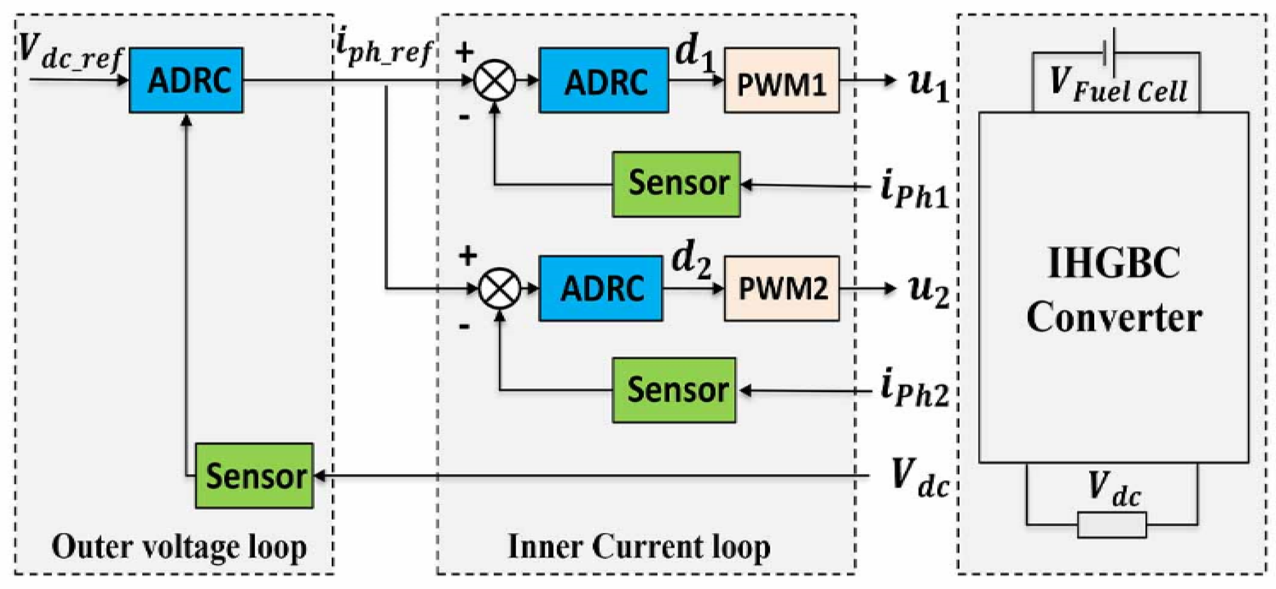
A robust dual-loop control application and design based on a linear active disturbance rejection control that controls the external voltage loop and the internal current loop of an interleaved DC-DC boost converter.
-
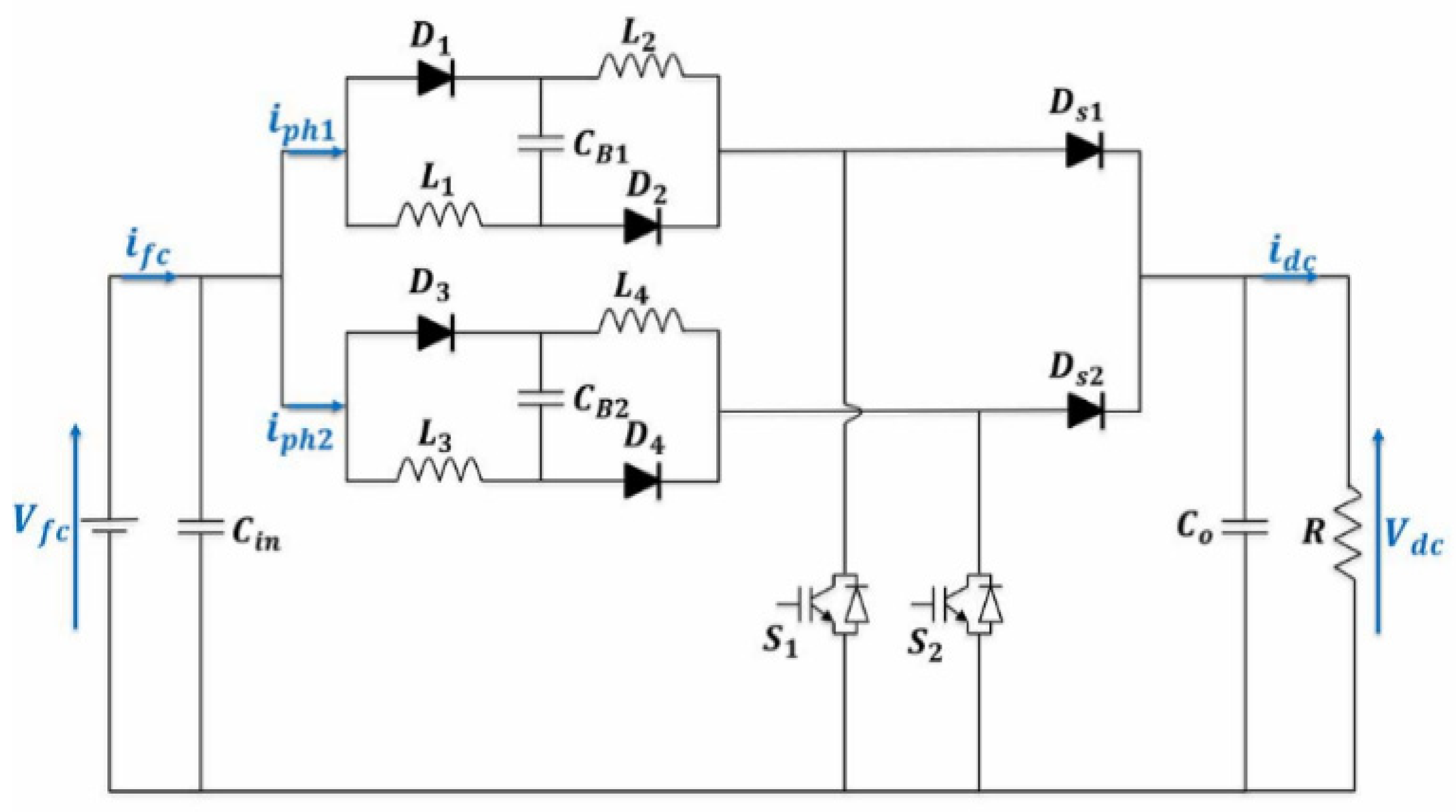
This converter provides high efficiency and high voltage gain with reduced voltage stress on switches and diodes.

2. PEMFC Modelling

In the literature, several electrochemical reaction models have been developed to predict the PEMFC supplied voltage. The purpose of this modeling is to obtain the PEMFC polarization characteristics, which are deduced from the current and voltage of the fuel cell. In this section, a cell voltage model is presented as follows [37]:
V F C = E N V A c t V O h m V C o n c
where E N is the fuel cell open circuit potential [37,38].
E N = 1.229 0.85 × 10 3 ( T F C 298.15 ) + 4.3085 × 10 5 T F C [ L n ( P H 2 1.01325 ) + 1 2 L n ( P O 2 1.01325 ) ]
V A c t are the activation losses expressed as a function of the constants V a , C 1 and the voltage drop V O .
V A c t = V O + V a ( 1 e C 1 i )
V O h m is the ohmic voltage drop and is calculated based on the temperature, membrane thickness of fuel cell and constants b 1 , b 2 [37].
V O h m = i . t m b 1 e x p ( b 2 ( 1 303 1 T F C ) )
The concentration losses V C o n c are given as a function of constants i M a x , C 2 and C 3 [37].
V C o n c = i ( C 2 i i M a x ) C 3

3. Modelling of the Proposed Converter

The interleaved high gain DC-DC boost converter (IHGBC) is shown in Figure 1. The circuit consist of two active switches (S1, S2), four inductors (L1, L2, L3, L4) and two boost capacitors (CB1, CB2) with equal values, one input capacitor (Cin), four passive switched inductor diodes (D1, D2, D3, D4), two output diodes (Ds1, Ds2) and one output capacitor (C0).
The interleaving concept used in this configuration is ensured by the parallel connection of two passive switched inductor cells at the input of the converter and the shifting of the control signals for the switches S1 and S2.
The interleaved topology reduces input current ripple. Moreover, this topology makes it possible to provide a high voltage gain and to reduce the electrical stresses (i.e., voltage and current) on the power semiconductors. The gain ratio of this topology is given by the following relationship:
V d c V F C = 2 1 d
The power switches (S1, S2) are controlled by switching each PWM gate control signal from each other by an angle of 180°.
When the switches (S1, S2) are turned on, diodes D1, D2, D3 and D4 are forward biased and L1, L2, L3, L4 and CB1, CB2 charge in parallel. When the switches (S1, S2) are turned off, then D1, D2, D3 and D4 are reverse biased and (L1, CB1 and L2), (L3, CB2 and L4) discharge in series.
The converter average model can be described by the equation:
{ L d I L d t = V i n ( 1 d ) 2 V d c                                                                         C d V d c d t = ( 1 d ) i L 1 + ( 1 d ) i L 2 + i d c
The small-signal model makes it possible to consider the transient and permanent state of the converter [39]. Therefore, we write:
x ( t ) = X ( t ) + x ˜
where x represents the variable, X represents the steady state and, finally, x ˜ represents the small variation around this steady state.
The average small-signal model of the converter is given below:
{ L s i ^ L = V ^ i n ( 1 d ) 2 V ^ d c + V o 2 d ^                                                                                               C s V ^ d c = ( 1 d ) i ^ L 1 I L 1 d ^ + ( 1 d ) i ^ L 2 I L 2 d ^ + i ^ d c
Assuming that the duty cycles ( d 1 , d 2 ) are identical, the different transfer functions of this converter with a resistive load R are given below.
V ^ d c d ^ = 2 R L I L s + R V d c ( 1 d ) 2 R L C s 2 + 2 L s + R ( 1 d ) 2
i ^ L d ^ = V d c R C s + R ( 1 d ) I L + V d c 2 R L C s 2 + 2 L s + R ( 1 d ) 2

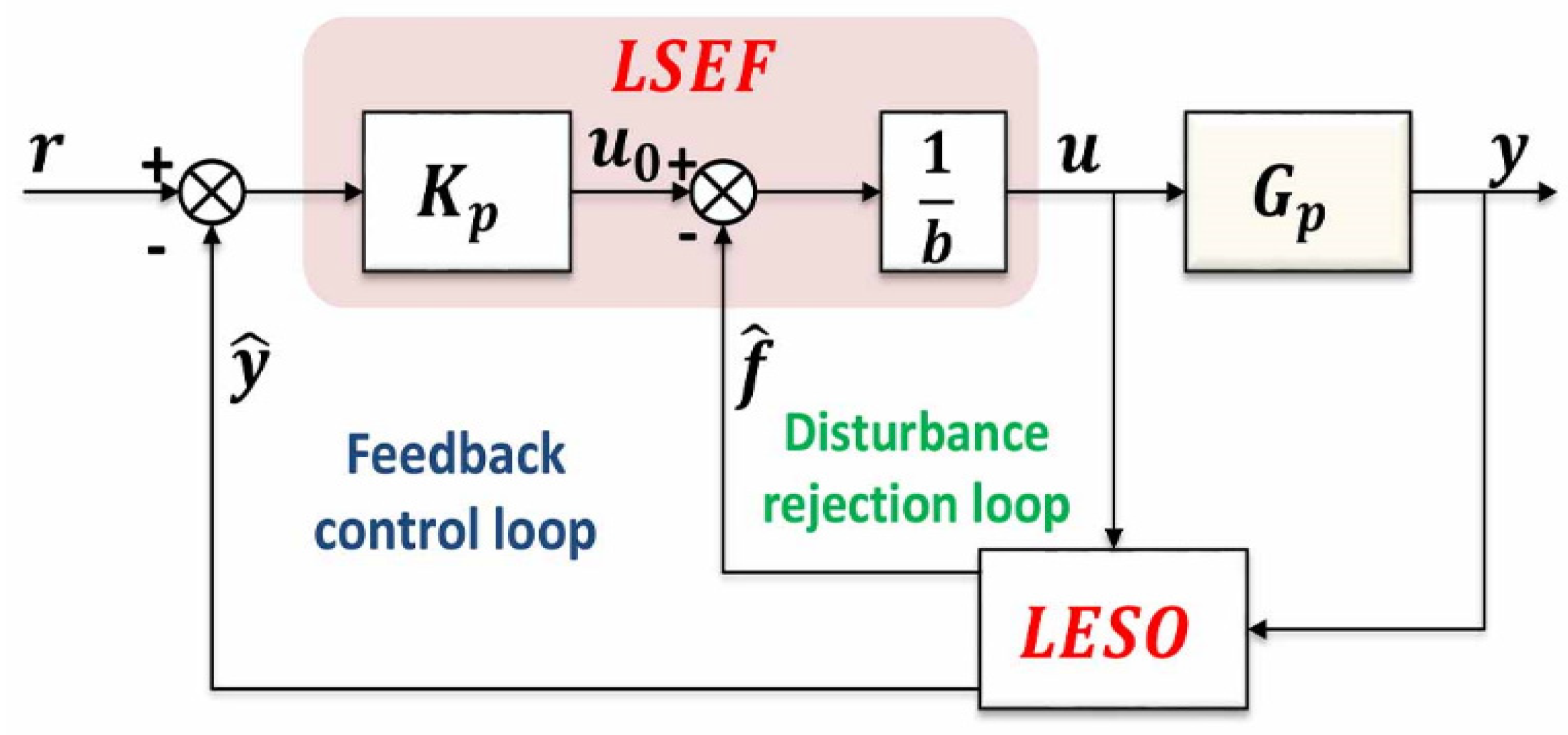
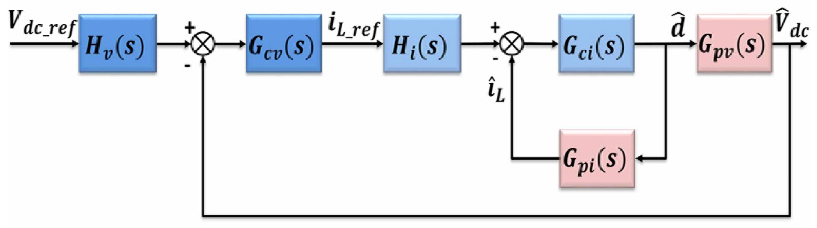
4. LADRC-Based Control Design

This work presents the application of a linear active disturbance rejection control on a DC-DC converter in order to ensure a good reference tracking of the DC bus voltage reference and improve the performance and stability of the control system.
The LADRC design is based on the effective estimation and compensation of internal and external disturbances. LADRC is an independent technique of the controlled system, which gives it an important advantage over traditional control methods.
LADRC contains a linear state error feedback (LSEF) control law, and a linear extended state observer (LESO). The structure is shown in Figure 2. The LADRC is composed of two main control loops: the inner loop, also called the disturbance rejection loop, and the outer loop, also called the feedback control loop. The total disturbances of the system are estimated in advance by the LESO and eliminated by the inner loop, which is combined with the feedback control loop to achieve the desired signal and improve the system stability.
Assuming that the exact mathematical model of the system is not known, and the external perturbation is ignored, the dynamics of the IHGBC system can be reformulated based on the approximate model in the LADRC framework as follows [27,36]:
y ˙ = b u + f ( y , u )
where y is the system output, f represents the total disturbance, u is the controlled quantity, and b is the system gain.
Let x 1 = y , x 2 = f then
{ x ˙ = A x + B u + E f ˙ y 1 = C x
where A = [ 0 1 0 1 ] ; B = [ b 0 ] ; E = [ 0 1 ] ; x = [ x 1 x 2 ] ; C = [ 1   0 ]
The corresponding second-order LESO is then written as follows:
{ x ^ ˙ = A x ^ + B u + L 0 ( y y ^ ) y ^ = C x ^
where L 0 = [ β 1 β 2 ] is the observer gain vector.
The total disturbance is estimated by properly designing the LESO and configuring the observer bandwidth ω 0 . To obtain the total perturbation compensation, the final control law is written as [27]:
u = u 0 f ^ b
where f ^ is the estimated value of the total disturbance, and u 0 is the control quantity before compensation.
Substitute Equation (15) into Equation (12) to obtain:
y ˙ = f x ^ 2 + u u
For first-order system, proportional control is adopted:
u 0 = K p ( r x ^ 1 )
where K p is the controller parameter and r is the input reference (see Figure 2).
By applying Laplace transform to (14) we can obtain [36]:
x ^ 1 = β 1 y s + k p r s s ( s + β 1 + k P )
x ^ 2 = β 2 y s + β 2 k p y + β 2 k p r s ( s + β 1 + k P )
To simplify the parameter tuning process, the setting of K p and L 0 is converted into the observer’s bandwidth ω 0 and the controller’s bandwidth ω c .
The needed settling time determines the controller parameter so K p = ω c with ω c 4 T s e t t l [36].
The observer bandwidth is often selected in an effort to balance the sensitivity to noise and the rapidity of state estimation. All of the observer poles are put at ω 0 by carefully choosing the observer gains, and the equation is found as β 1 = 2 ω 0 ; β 2 = ω 0 2 .
There is a general rule based on selection ω 0 = 3 ~ 10 ω c .
Finally, the value of b is required to be increased incrementally until the desired performance is reached [36].
The DC-DC converter control loop is designed with a linear active disturbance rejection control that contains two cascaded loops (Figure 3): an outer loop for DC bus voltage control and an inner loop for phase current control. The DC bus voltage controller produces an i p h . r e f by the error between the desired voltage value and the observed DC bus voltage, then the inner current loop allows the control signals ( d 1 , d 2 ) to be generated.
The current controller parameters are designed using the transfer function given by Equation (7) as follows:
d I L d t = ( 1 d ) U d c 2 L + U i n L
Let I L = y 1 , d = u 1 then:
y ˙ 1 = U d c 2 L u 1 + U i n L U d c 2 L = b 1 u 1 + f 1 ( y 1 , u 1 )
where b 1 = U d c 2 L is the object gain, u 1 is the system input, f 1 = 2 U i n U d c 2 L is the total disturbance and y 1 is the system output.
Let x 1 = y 1 , x 2 = f 1 then:
{ x ˙ = A 1 x + B 1 u 1 + E 1 f ˙ 1 y 1 = C 1 x                                                      
where A 1 = [ 0 1 0 1 ] ; B 1 = [ b 1 0 ] ; E 1 = [ 0 1 ] ; x = [ x 1 x 2 ] ; C 1 = [ 1   0 ]
Second-order LESO is [30]:
{ x ^ ˙ = A 1 x ^ + B 1 u 1 + L 1 ( y 1 y ^ 1 ) y ^ 1 = C 1 x ^
where L 1 = [ β 11 β 12 ]
The final control law is designed to achieve aggregate compensation for disturbance as follows [30]:
u 1 = u 0 x ^ 2 b 1
Substituting Equation (24) into Equation (21):
y ˙ 1 = f 1 x ^ 2 + u 1 u 1
Considering the controlled plant as a first-order system, a linear proportional controller can be used of the form:
u 0 = K p i ( r 1 x ^ 1 )
Based on the concept of bandwidth, the tuning of L 1 and K p i is simplified.
β 11 = 2 ω 01 ; β 12 = ω 01 2 ; K p i = ω c 1
In the same way as the study of the design of the current controller, the voltage controller parameters are designed using the transfer function given by Equation (7) as follows:
d U d c d t = ( 1 d ) I L C U d c R C
Let U d c = y 2   , I L = u 2 then:
y ˙ 2 = ( 1 d ) C u 2 y 2 R C = b 2 u 2 + f 2 ( y 2 , u 2 )
where b 1 = ( 1 d ) C is the system gain, u 2 is the system input, f 1 = y 2 R C is the total disturbance of the system and y 2 is the system output.
Let x 1 = y 2 , x 2 = f 2 then:
{ x ˙ = A 2 x + B 2 u 2 + E 2 f ˙ 2 y 2 = C 2 x                                                      
where A 2 = [ 0 1 0 1 ] ; B 2 = [ b 2 0 ] ; E 2 = [ 0 1 ] ; x = [ x 1 x 2 ] ; C 2 = [ 1   0 ] .
Second-order LESO is:
{ x ^ ˙ = A 2 x ^ + B 2 u 2 + L 2 ( y 2 y ^ 2 ) y ^ 2 = C 2 x ^                                                                                  
where L 2 = [ β 21 β 22 ]
The control law is designed to compensate the disturbances as follows:
u 2 = u 0 x ^ 2 b 2
Thus, Equation (28) becomes:
y ˙ 2 = f 2 x ^ 2 + u 2 u 2
and the controlled plant is easily regulated using a proportional controller:
u 0 = K p v ( r 2 x ^ 2 )
The parameter setting for L 2 and K p v is simplified as follows:
β 21 = 2 ω 02 ; β 22 = ω 02 2 ; K p v = ω c 2
Figure 4 shows the block diagram of the proposed control for one phase. From Figure 4, the gain of the internal current loop is equal to:
G i ( s ) = G c i ( s ) H i ( s ) 1 + G c i ( s )   G p i ( s )
and the gain of the external voltage loop is obtained as:
G v ( s ) = G c v ( s ) H v ( s ) G c i ( s ) H i ( s ) G p v ( s ) G p i ( s ) 1 + G c i ( s )   G p i ( s )
In Figure 4, H v ( s ) and G c v ( s ) represent the outer voltage loop of the LADRC to obtain the phase current reference from the difference between the measured DC bus voltage and the reference DC bus voltage, and H i ( s ) and G c i ( s ) represent the LADRC inner current loop, which allows the duty cycle from the difference between the measured current and the reference current to be obtained.
G p v ( s ) and G p i ( s ) are the transfer functions defined, respectively, with the following equations.
G p v ( s ) = V ^ d c d ^ = 2 R L I L s + D R V d c 2 R L C s 2 + 2 L s + D R
G p i ( s ) = i ^ L d ^ = V d c R C s + D R I L + V d c 2 R L C s 2 + 2 L s + D R
where R is the load, and D = 1 d .
By combining (18), (19), (24), (26), (31) and (33), the LADRC transfer functions-based control law can be expressed as:
H v ( s ) = k P v ( s 2 + β 21 s + β 22 ) ( k P v β 21 + β 22 ) s + k p v β 22
G c v ( s ) = 1 b 2 ( k P v β 21 + β 22 ) s + k p v β 22 s ( s + β 21 + k P v )
H i ( s ) = k P i ( s 2 + β 11 s + β 12 )   ( k P i β 11 + β 12 ) s + k p i β 12
G c i ( s ) = 1 b 1 ( k P i β 11 + β 12 ) s + k p i β 12 s ( s + β 11 + k P i )

5. Simulation Results

The simulations of the IHGBC converter and the proposed LADRC control were performed using MATLAB/SIMULINK. The performance and stability of the system are checked under different operating scenarios and the proposed controller is compared with the classical PI controller and sliding mode control (SMC) to prove the advantage of the proposed strategy. Table 1 shows the simulation parameters used for the IHGBC converter and controller.
First, the performance of the proposed converter is evaluated in an open loop by performing tests at different duty cycle values. The obtained results are shown in Figure 5a–d. During the entire operation, the input voltage is fixed at 20 V with a load resistance of 100 Ω.
Figure 5a–c show the input current, phase currents and inductor currents at duty cycle values of 0.3, 0.5, 0.67, respectively, while Figure 5d represents the obtained output voltage values. The output voltage ranges from 57 V to 121 V with a duty cycle change from 0.3 to 0.67.
These results confirm the ability of the proposed converter to achieve high voltage gain with less current ripple. Moreover, the evolution of the output voltage and the duty cycle correspond to Equation (6).
Second, the output voltage reference was increased from 100 to 120 volts and then decreased from 120 to 100 volts in order to test the robustness of the proposed controller.
Figure 6 shows the output voltage response of the conventional PI, sliding mode control and the proposed LADRC controller. As can be seen, the proposed LADRC controller provides better performance with a fast response and perfect traceability of the output voltage reference compared to PI control and sliding mode control.
To further verify the efficiency of the IHGBC converter, and the proposed LADRC control, the converter is controlled in a closed loop in order to regulate the DC bus voltage to multiple values, between 80 and 200 volts. The input voltage is set to 20 V with a 150 Ω resistance load.
Figure 7 confirms that the proposed converter has the ability to provide good efficiency and high voltage gain. The results also confirmed, once again, the efficiency of the LADRC to deliver the DC bus voltage to the desired value faster.
The output voltage reference is fixed at a value of 100 and then 120 volts, then the stability of the system is tested under different operating points (different input voltage values and load resistance are selected).
Figure 8 shows the converter performance of the proposed LADRC controller, sliding mode control and the PI controller. By comparing the results of the three methods under similar conditions, the LADRC controller provides optimum performance with voltage stability at different operating points. In contrast, the performance of the SMC and PI controller records overshoots and deviations from the output voltage reference as operating points change.

6. Experimental validation

In order to test and verify the robustness and the efficiency of the proposed LADRC dual-loop control, tests were carried out on an experimental prototype of the interleaved gain high DC-DC boost converter, as shown in Figure 9.
The experimental test bench consists of a real-time PEMfc system emulator to reproduce the same characteristics of a real PEMfc, an IHGBC DC/DC converter, a resistive load, a measurement card, a development real-time card and, finally, a PC to save the data obtained using MATLAB software.
The fuel cell model presented in Section 2 and the DC/DC converter control methods are implemented on a real-time board, the latter being used for the control and data acquisition of the IHGBC converter and FC emulator.
The operation principle of the PEMFC emulator is presented in Figure 10; it consists mainly of a DC/DC buck converter. The output current of this converter is used as input to the fuel cell model. The model allows the reference voltage to be used, which is compared to the measured voltage, and regulated using a PI regulator, to generate the PWM control signals, so the buck converter is controlled in the voltage.
The PWM gate control signals are generated by a PWM signal generator block provided by the real-time board library in the MATLAB Simulink environment. The IHGBC converter and controller’s parameters are summarized in Table 2.
Various operating modes are made to check the behavior of the considered system and the proposed controller.
The superiority of the proposed method was first demonstrated by comparing the proposed LADRC controller with the classical PI controller. The main purpose is to make the DC bus voltage follow its reference and provide a disturbances rejection.
Figure 11, Figure 12 and Figure 13 show the system response for a reference change in the output voltage from 100 V to 120 V between moment 4 s and 6 s.
As can be seen from Figure 11, the two controllers can reach the desired value, but the proposed LADRC proves its superiority by perfect tracking of the output voltage reference with a fast response and without any overshoot during rise or fall. The phase current response after the reference change in the output voltage is shown in Figure 12.
An increase in output voltage leads to an increase in phase current and PEMFC emulator current, and, consequently, the PEMFC emulator voltage decreases depending on the fuel cell nature, as shown in Figure 13.
Second, to check how well the controller can ensure a stable output voltage under different loads, a variable load current is applied, by abruptly changing the load resistance from 150 Ω to 100 Ω. The phase current rises from 2 A to 3 A during this period (Figure 14) to meet the load requirements, while the proposed control algorithm reacts instantly in order to maintain the output voltage constant at the desired reference, as shown in Figure 15. At the same time, Figure 16 shows that the controller PI takes a long response time and with greater deflection.
Figure 17 shows the PEMFC emulator current and voltage, respectively.

7. Conclusions

To improve the control performance and ensure the stability and fast response of the DC/DC boost converter under parameter uncertainties and disturbances, a robust two-loop control based on a linear active disturbance rejection control is proposed in this paper. It includes an internal current control loop and an external voltage control loop of an interleaved high gain DC/DC boost converter associated with the proton exchange membrane fuel cell system. This converter provides high efficiency and high voltage gain with reduced voltage stress on the switches and diodes. In addition, the interleaving technique and the parallel structure of the converter guarantee low input current ripple and reduce the size of the passive components and its modularity also offers fault tolerant capabilities.
The robustness and effectiveness of the proposed controller have been confirmed by simulations and experimental results. The results showed that the proposed control unit provides good dynamic performance and stability under different operating conditions. Moreover, the performance of the proposed control still needs to be verified against other advanced control techniques. Additionally, a number of ongoing research studies show that strong robustness can be provided by relying on a hybrid control between LADRC and other control algorithms, and this will be one of the directions of our future research.

Author Contributions

Conceptualization, A.A.S.; methodology, A.A.S.; software, A.A.S., F.K. and A.B.; validation, A.A.S. and F.K.; formal analysis, A.A.S. and F.K.; investigation, A.A.S., M.B. and Y.A.; resources, M.B. and Y.A.; data curation, A.A.S. and F.K.; writing—original draft preparation, A.A.S.; writing—review and editing, A.A.S., F.K., Y.A., A.B. and M.B.; visualization, A.A.S., F.K. and A.B.; supervision, M.B. and F.K.; project administration, M.B. and Y.A. All authors have read and agreed to the published version of the manuscript.

Funding

This research received no external funding.

Institutional Review Board Statement

Not applicable.

Informed Consent Statement

Not applicable.

Data Availability Statement

Not applicable.

Conflicts of Interest

The authors declare no conflict of interest.

References

  1. Dafalla, A.M.; Wei, L.; Habte, B.T.; Guo, J.; Jiang, F. Membrane Electrode Assembly Degradation Modeling of Proton Exchange Membrane Fuel Cells: A Review. Energies 2022, 15, 9247. [Google Scholar] [CrossRef]
  2. Badoud, A.E.; Mekhilef, S.; Ould Bouamama, B. A Novel Hybrid MPPT Controller Based on Bond Graph and Fuzzy Logic in Proton Exchange Membrane Fuel Cell System: Experimental Validation. Arab. J. Sci. Eng. 2022, 47, 3201–3220. [Google Scholar] [CrossRef]
  3. Mounica, V.; Obulesu, Y.P. Hybrid Power Management Strategy with Fuel Cell, Battery, and Supercapacitor for Fuel Economy in Hybrid Electric Vehicle Application. Energies 2022, 15, 4185. [Google Scholar] [CrossRef]
  4. Smadi, A.A.; Khoucha, F.; Benrabah, A.; Benbouzid, M. An Improved Model for Fault Tolerant Control of a Flooding and Drying Phenomena in the Proton Exchange Membrane Fuel Cell. In Advances in Renewable Hydrogen and Other Sustainable Energy Carriers; Khellaf, A., Ed.; Springer Proceedings in Energy, Springer: Singapore, 2021. [Google Scholar] [CrossRef]
  5. Bi, H.; Wang, P.; Che, Y. A capacitor clamped H-type boost DC-DC converter with wide voltage-gain range for fuel cell vehicles. IEEE Trans. Veh. Technol. 2019, 68, 276–290. [Google Scholar] [CrossRef]
  6. Zhang, Y.; Zhou, L.; Sumner, M.; Wang, P. Single-switch, wide voltage-gain range, boost DC–DC converter for fuel cell vehicles. IEEE Trans. Veh. Technol. 2018, 67, 134–145. [Google Scholar] [CrossRef]
  7. Guilbert, D.; Gaillard, A.; Mohammadi, A.; N’Diaye, A.; Djerdir, A. Investigation of the interactions between proton exchange membrane fuel cell and interleaved DC/DC boost converter in case of power switch faults. Int. J. Hydrogy Energy 2015, 40, 519–537. [Google Scholar] [CrossRef]
  8. Saadi, R.; Hammoudi, M.Y.; Kraa, O.; Ayad, M.Y.; Bahri, M. A robust control of a 4-leg floating interleaved boost converter for fuel cell electric vehicle application. Math. Comput. Simulat. 2020, 167, 32–47. [Google Scholar] [CrossRef]
  9. Kirubakaran, A.; Jain, S.; Nema, R. A review on fuel cell technologies and power electronic interface. Renew Sustain. Energy Rev. 2009, 13, 2430–2440. [Google Scholar] [CrossRef]
  10. Hasan, N.S.; Rosmin, N.; Osman, D.A.A.; Musta’amal, A.H. Reviews on multilevel converter and modulation techniques. Renew. Sustain. Energy Rev. 2017, 80, 163–174. [Google Scholar] [CrossRef]
  11. Kolli, A.; Gaillard, A.; De Bernardinis, A.; Bethoux, O.; Hissel, D.; Khatir, Z. A review on DC/DC converter architectures for power fuel cell applications, Energy Convers. Energy Convers. Manag. 2015, 105, 716–730. [Google Scholar] [CrossRef]
  12. Seguel, J.L.; Seleme, S.I., Jr.; Morais, L.M.F. Comparative Study of Buck-Boost, SEPIC, Cuk and Zeta DC-DC Converters Using Different MPPT Methods for Photovoltaic Applications. Energies 2022, 15, 7936. [Google Scholar] [CrossRef]
  13. Smadi, A.; Khoucha, F.; Benrabah, A.; Benbouzid, M. Interleaved High Gain DC/DC Boost Converter-Based Proton Exchange Membrane Fuel Cell Fault-Tolerant Control. Int. Rev. Electr. Eng. (IREE) 2022, 17, 447–459. [Google Scholar] [CrossRef]
  14. Hwu, K.I.; Yau, Y.T. High Step-Up Converter Based on Charge Pump and Boost Converter. IEEE Trans. Power Electron. 2012, 27, 2484–2494. [Google Scholar] [CrossRef]
  15. Mariscotti, A. Power Quality Phenomena, Standards, and Proposed Metrics for DC Grids. Energies 2021, 14, 6453. [Google Scholar] [CrossRef]
  16. Gerard, M.; Poirot-Crouzevier, J.P.; Hissel, D.; Pera, M.C. Ripple Current Effects on PEMFC Aging Test by Experimental and Modeling. ASME. J. Fuel. Cell Sci. Technol. 2011, 8, 021004. [Google Scholar] [CrossRef]
  17. Uno, M.; Tanaka, K. Pt/C catalyst degradation in proton exchange membrane fuel cells due to high-frequency potential cycling induced by switching power converters. J. Power Sources 2011, 196, 9884–9889. [Google Scholar] [CrossRef]
  18. Forouzesh, M.; Siwakoti, Y.P.; Gorji, S.A.; Blaabjerg, F.; Lehman, B. Step-Up DC-DC converters: A comprehensive review of voltage-boosting techniques, topologies, and applications. IEEE Trans. Power. Electron. 2017, 32, 9143–9178. [Google Scholar] [CrossRef]
  19. Kobaku, T.; Patwardhan, S.C.; Agarwal, V. Experimental evaluation of internal model control scheme on a DC–DC boost converter exhibiting nonminimum phase behavior. IEEE Trans. Power. Electron. 2017, 32, 8880–8891. [Google Scholar] [CrossRef]
  20. Wang, W.Y.; Ding, Y.H.; Ke, X.; Ma, X. Sliding mode control of direct coupled interleaved boost converter for fuel cell. In IOP Conference Series: Earth and Environmental Science; Conference 1; IOP Publishing: Bristol, UK, 2017; Volume 100. [Google Scholar] [CrossRef]
  21. Thammasiriroj, W.; Chunkag, V.; Phattanasak, M.; Pierfederici, S.; Davat, B.; Thounthong, P. Nonlinear single-loop control of the parallel converters for a fuel cell power source used in DC grid applications. Int. J. Electr. Power Energy Syst. 2015, 65, 41–48. [Google Scholar] [CrossRef]
  22. Hammoudi, M.Y.; Saadi, R.; Cardoso, A.; Benbouzid, M.; Mohamed, S. Practical implementation of H-infinity control for fuel cell-interleaved boost converter. Int. J. Model. Simulat. 2018, 40, 44–61. [Google Scholar] [CrossRef]
  23. Mumtaz, F.; Yahaya, N.Z.; Meraj, S.T.; Singh, B.; Kannan, R.; Ibrahim, O. Review on non-isolated DC-DC converters and their control techniques for renewable energy applications. Ain. Shams. Eng. J. 2021, 12, 3747–3763. [Google Scholar] [CrossRef]
  24. Venkatesan, M.; Rajamanickam, N.; Vishnuram, P.; Bajaj, M.; Blazek, V.; Prokop, L.; Misak, S. A Review of Compensation Topologies and Control Techniques of Bidirectional Wireless Power Transfer Systems for Electric Vehicle Applications. Energies 2022, 15, 7816. [Google Scholar] [CrossRef]
  25. Kanouni, A.; Badoud, A.; Mekhilef, S. A multi-objective model predictive current control with two-step horizon for double-stage grid-connected inverter PEMFC system. Int. J. Hydrog. Energy 2022, 47, 2685–2707. [Google Scholar] [CrossRef]
  26. Maroufi, O.; Choucha, A.; Chaib, L. Hybrid fractional fuzzy PID design for MPPT-pitch control of wind turbine-based bat algorithm. Electr. Eng. 2020, 102, 2149–2160. [Google Scholar] [CrossRef]
  27. Han, J. From PID to active disturbance rejection control, IEEE Trans. Ind. Electron. 2009, 56, 900–906. [Google Scholar] [CrossRef]
  28. Huang, Y.; Xue, W. Active disturbance rejection control: Methodology and theoretical analysis. ISA Trans. 2014, 53, 963–976. [Google Scholar] [CrossRef]
  29. Gao, Z. Scaling and bandwidth-parameterization based controller tuning. Proc. Amer. Control. Conf. 2003, 4989–4996. [Google Scholar]
  30. Li, H.; Liu, X.X.; Lu, J.W. Research on Linear Active Disturbance Rejection Control in DC/DC Boost Converter. Electronics 2019, 8, 1249. [Google Scholar] [CrossRef] [Green Version]
  31. Chiumeo, R.; Raggini, D.; Veroni, A.; Clerici, A. Comparative Analysis of PI and ADRC Control through CHIL Real Time Simulations of a DC-DC DAB into a Multi-Terminal MVDC/LVDC Distribution Network. Energies 2022, 15, 7631. [Google Scholar] [CrossRef]
  32. Wang, J.; Wang, X.; Luo, Z.; Assadian, F. Active Disturbance Rejection Control of Differential Drive Assist Steering for Electric Vehicles. Energies 2020, 13, 2647. [Google Scholar] [CrossRef]
  33. Li, H.; Qu, Y. A Composite Strategy for Harmonic Compensation in Standalone Inverter Based on Linear Active Disturbance Rejection Control. Energies 2019, 12, 2618. [Google Scholar] [CrossRef] [Green Version]
  34. Zuo, Y.; Zhu, X.; Li, Q.; Chao, Z.; Yi, D.; Xiang, Z. Active Disturbance Rejection Controller for Speed Control of Electrical Drives Using Phase-locking Loop Observer. IEEE Trans. Ind. Electron. 2019, 66, 1748–1759. [Google Scholar] [CrossRef]
  35. Alicia, L.; Keow, J.; Mayhall, A.; Cescon, M.; Chen, Z. Active disturbance rejection control of metal hydride hydrogen storage. Int. J. Hydrog. Energy 2021, 46, 837–851. [Google Scholar] [CrossRef]
  36. Benrabah, A.; Xu, D.; Gao, Z. Active disturbance rejection control of LCL filtered grid-connected inverter using pade approximation. IEEE Trans. Ind. Appl. 2018, 54, 6179–6189. [Google Scholar] [CrossRef]
  37. Pukrushpan, J.T.; Peng, H.; Stefanopoulou, A.G. Control oriented modeling and analysis for automotive fuel cell systems. J. Dyn. Sys. Meas. Control. 2004, 126, 14–25. [Google Scholar] [CrossRef]
  38. Wu, X.; Zhou, B. Fault tolerance control for proton exchange membrane fuel cell systems. J. Power Sources 2016, 324, 804–829. [Google Scholar] [CrossRef]
  39. De Bernardinis, A.; Candusso, D.; Harel, F.; Coquery, G. Power Electronics Interface for an Hybrid PEMFC Generating System with Fault Management Strategies for Transportation. In Proceedings of the European Conference on Power Electronics and Application, Barcelona, Spain, 8–10 September 2009. [Google Scholar]
Figure 1. Structure of the proposed interleaved high gain DC-DC boost converter.
Energies 16 01019 g001
Figure 2. Structure diagram of the LADRC.
Energies 16 01019 g002
Figure 3. Cascaded control scheme for IHGBC.
Energies 16 01019 g003
Figure 4. Control structure of IHGBC for one phase.
Energies 16 01019 g004
Figure 5. IHGBC simulation results: (ac) show the input current, phase currents and inductor currents at duty cycle values of 0.3, 0.5, and 0.67, respectively. While (d) the obtained output voltage values.
Energies 16 01019 g005
Figure 6. Output voltage responses.
Energies 16 01019 g006
Figure 7. Output voltage response for different voltage reference.
Energies 16 01019 g007
Figure 8. Output voltage responses with different operation points, (a) PI control (b) SMC (c) proposed LADRC. Case 1: Vfc = 15 V, R = 100 Ω; case 2: Vfc = 15 V, R = 200 Ω; case 3: Vfc = 20 V, R = 150 Ω; case 4: Vfc = 25 V, R = 100 Ω; case 5: Vfc = 25 V, R = 200 Ω.
Energies 16 01019 g008
Figure 9. Experimental test bench.
Energies 16 01019 g009
Figure 10. Architecture of PEMFC emulator.
Energies 16 01019 g010
Figure 11. Output voltage responses.
Energies 16 01019 g011
Figure 12. IHGBC phase current.
Energies 16 01019 g012
Figure 13. PEMFC emulators current and voltage.
Energies 16 01019 g013
Figure 14. IHGBC phase current.
Energies 16 01019 g014
Figure 15. Output voltage response.
Energies 16 01019 g015
Figure 16. Output voltage response.
Energies 16 01019 g016
Figure 17. PEMFC emulator’s current and voltage.
Energies 16 01019 g017
Table 1. Simulation parameters.
ParametersSpecifications
DC bus voltage Vbus80–200 V
Switching frequency, fs10 KHz
Inductors, L1, L2, L3, L4440 μH
Boost capacitors CB1, CB2 47 μF /100 V
Input capacitor, Cin4.7 mF/400 V
Output capacitor, Co330 μF /400 V
ω c 1 , ω 01 , b 1 1200, 6000, 21,000
ω c 2 , ω 02 , b 2 50, 450, 490
PI parameters (voltage loop), Kp1, Ki10.4, 4.5
PI parameters (current loop), Kp2, Ki20.5, 30
Table 2. Experimental parameters.
ParametersSpecifications
Switching frequency, fs10 KHz
Inductors, L1, L2, L3, L4440 μH
Boost capacitors CB1, CB2 47 μF/100 V
Input capacitor, Cin4.7 mF/400 V
Output capacitor, Co330 μF/400 V
Switch ‘S1′, ‘S2′IRFP260 (200 V, 50 A)
Diodes D1, D2, D3, D4, DoRHRG3060
Diodes Ds1, Ds2RHRG3060
ω c 1 ,   ω 01 ,   b 1 500, 1750, 1600
ω c 2 ,   ω 02 ,   b 2 30, 270, 851
PI parameters (voltage loop), Kp1, Ki10.05, 0.5
PI parameters (current loop), Kp2, Ki20.01, 10
Disclaimer/Publisher’s Note: The statements, opinions and data contained in all publications are solely those of the individual author(s) and contributor(s) and not of MDPI and/or the editor(s). MDPI and/or the editor(s) disclaim responsibility for any injury to people or property resulting from any ideas, methods, instructions or products referred to in the content.

