
Overview of Integration of Power Electronic Topologies and Advanced Control Techniques of Ultra-Fast EV Charging Stations in Standalone Microgrids


Abstract
:1. Introduction
2. International Standards for Ultra-Fast Charging Stations
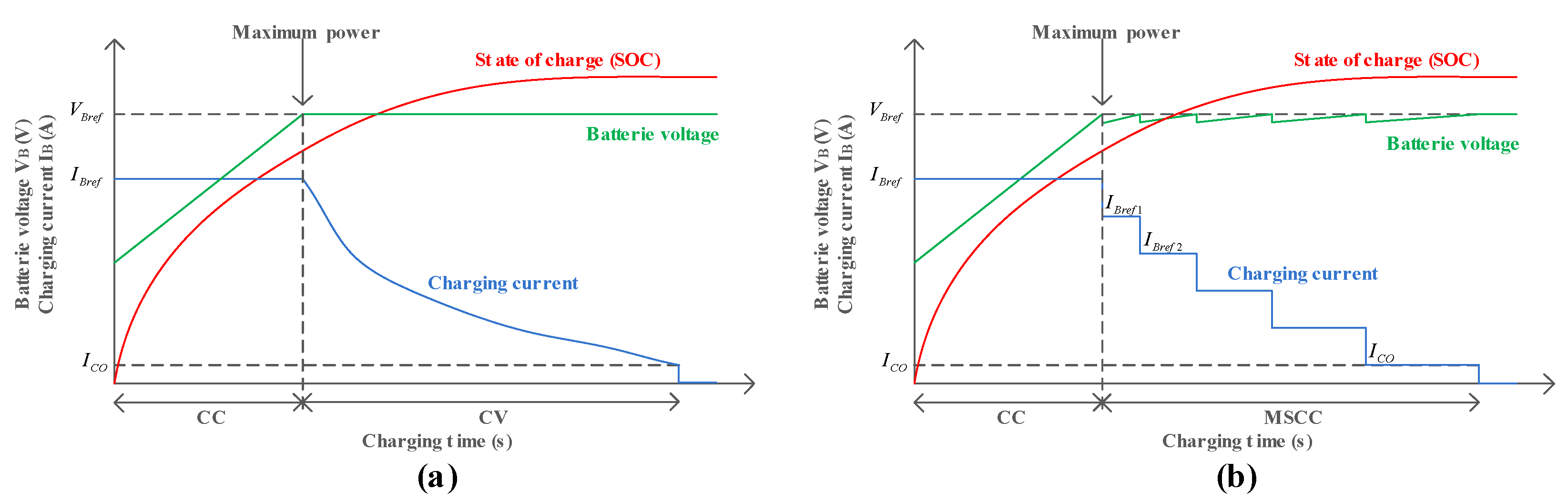
3. Types of Fast Charging Methods
4. Different Power Electronic Topologies of Ultra-Fast Charger
4.1. AC-DC Power Converters
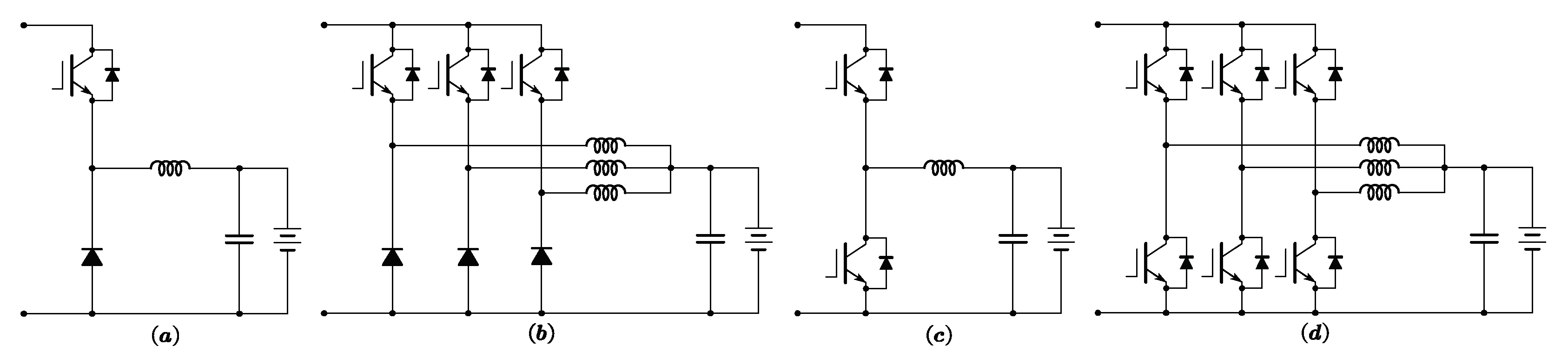
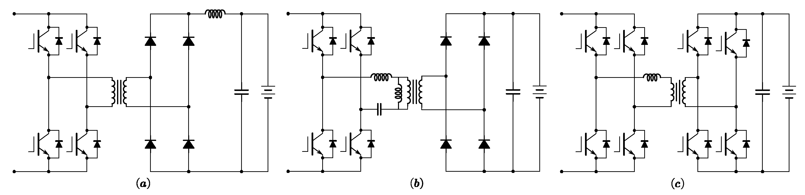
4.2. DC-DC Power Converters
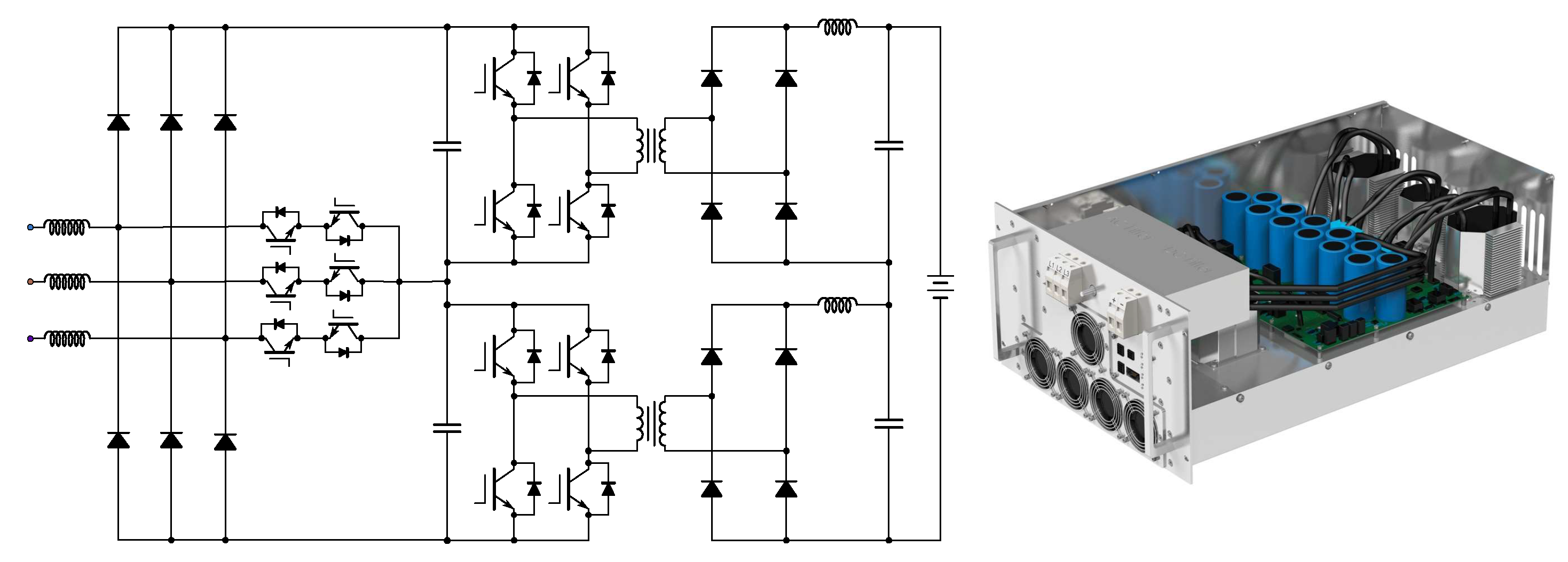
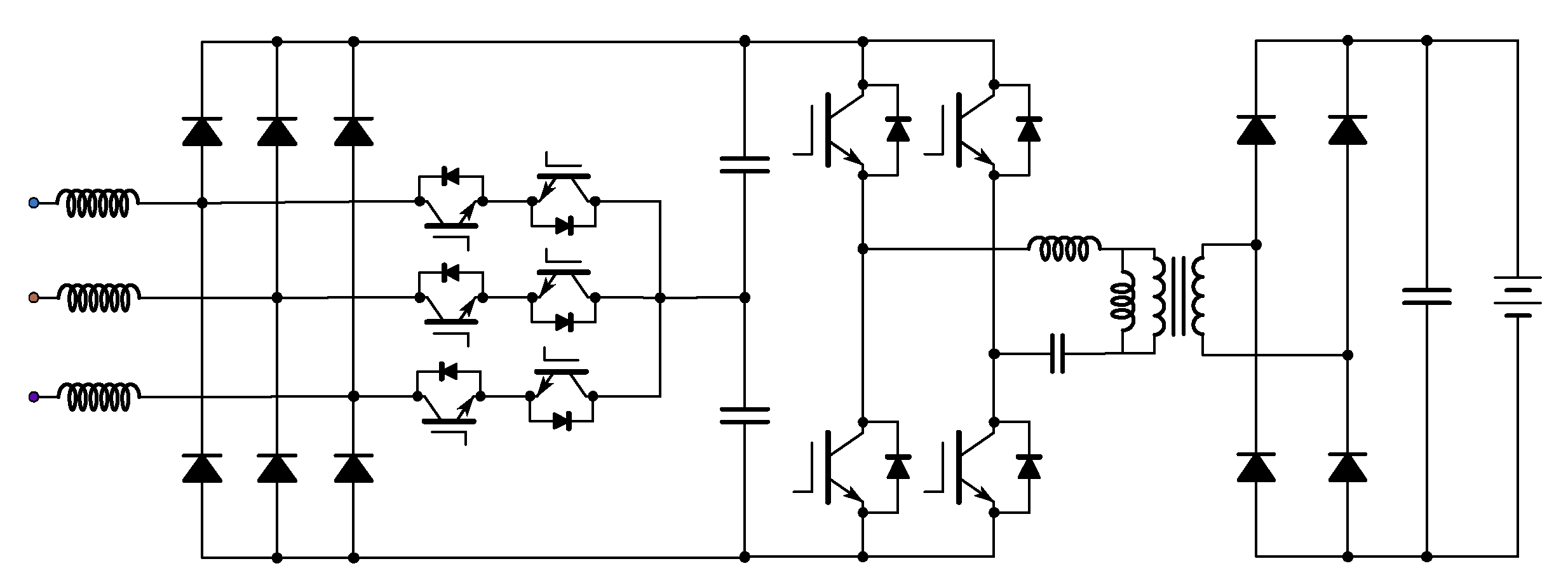
4.3. Industrial Applications
5. Modular Design Approach
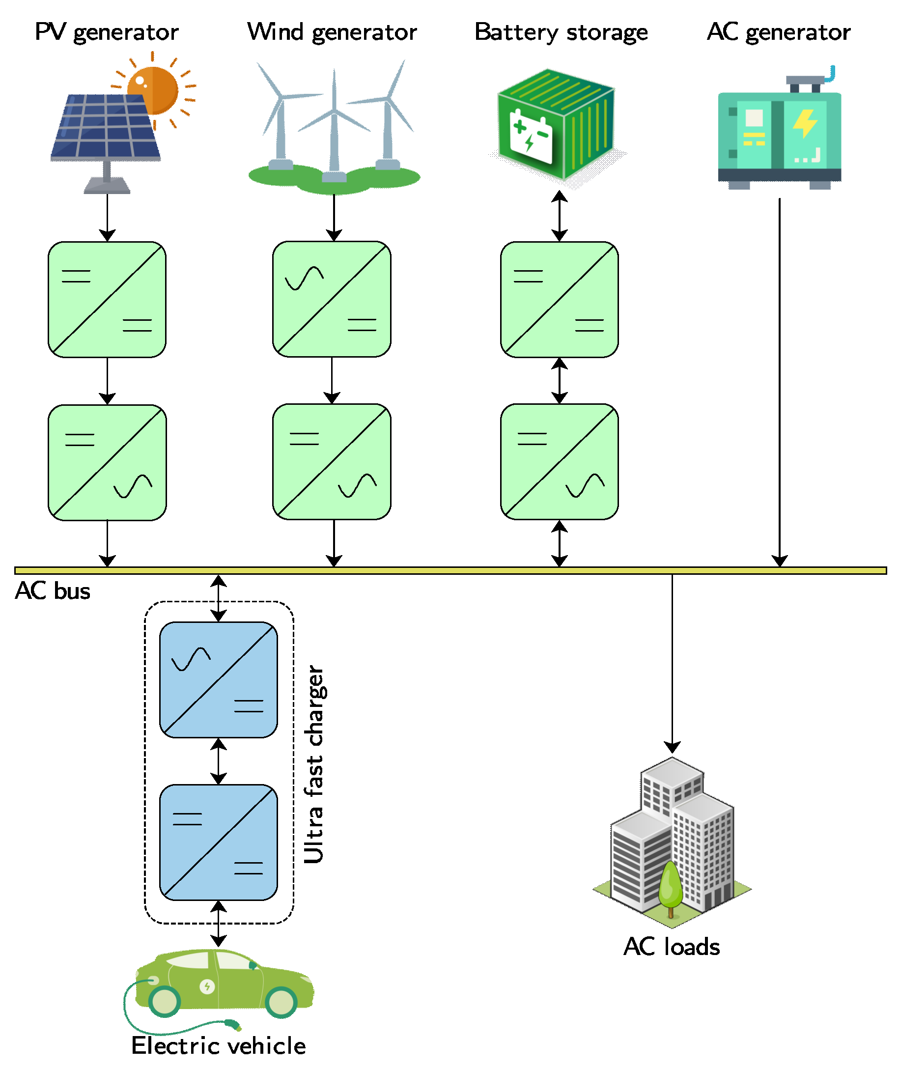
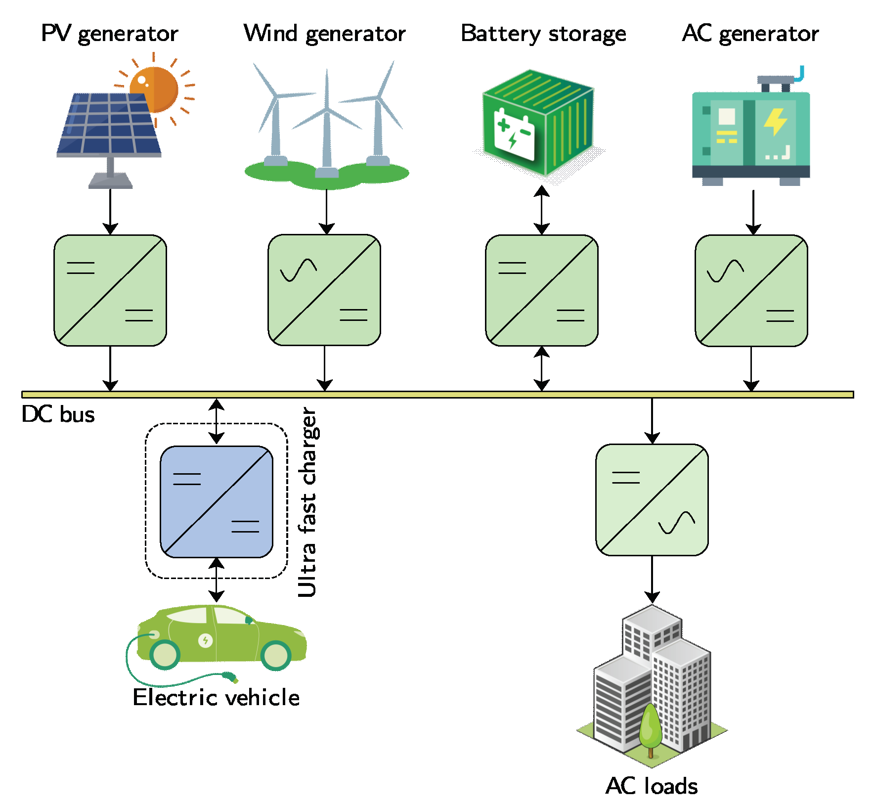
6. Integration of Ultra-Fast Chargers into Standalone Microgrids
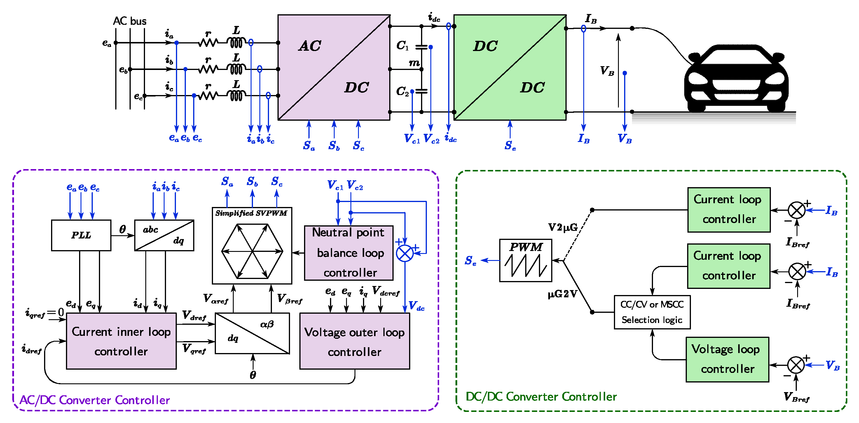
7. Advanced Control Techniques for Ultra-Fast Chargers Integrated into Standalone Microgrids
8. Conclusions
Author Contributions
Funding
Data Availability Statement
Conflicts of Interest
References
- IEA. Global EV Outlook 2021. 2021. Available online: www.iea.org/reports/global-ev-outlook-2021 (accessed on 24 April 2022).
- Pratheesh, K.; Ghosh, S.; Mangal, N.; Poulose, R.; Narayanan, R. DC Fast Charging Stations. Technology and challenges, SFO Technologies. 2021. Available online: www.sfotechnologies.net (accessed on 25 April 2022).
- Eaton. Essential Guide to Electric Vehicle Charging. March 2021. Available online: www.eaton.com (accessed on 25 April 2022).
- Nicholas, M.; Hall, D. Lessons Learned on Early Electric Vehicle Fast-Charging Deployments, icct, August 2018. Available online: www.theicct.org/publication/lessons-learned-on-early-electric-vehicle-fast-charging-deployments/ (accessed on 26 April 2022).
- Singh, R.; Padmanaban, S.; Dwivedi, S.; Molinas, M.; Blaabjerg, F. Cable Based and Wireless Charging Systems for Electric Vehicles: Technology and Control, Management and Grid Integration; The Institution of Engineering and Technology: London, UK, 2022. [Google Scholar]
- Chang, M.; Bae, S.; Cha, G.; Yoo, J. Aggregated Electric Vehicle Fast-Charging Power Demand Analysis and Forecast Based on LSTM Neural Network. Sustainability 2021, 13, 13783. [Google Scholar] [CrossRef]
- Ali, A.; Shakoor, R.; Raheem, A.; Muqeet, H.A.u.; Awais, Q.; Khan, A.A.; Jamil, M. Latest Energy Storage Trends in Multi-Energy Standalone Electric Vehicle Charging Stations: A Comprehensive Study. Energies 2022, 15, 4727. [Google Scholar] [CrossRef]
- Shakeel, F.M.; Malik, O.P. Vehicle-To-Grid Technology in a Micro-grid Using DC Fast Charging Architecture. In Proceedings of the 2019 IEEE Canadian Conference of Electrical and Computer Engineering (CCECE), Edmonton, AB, Canada, 5–8 May 2019; pp. 1–4. [Google Scholar] [CrossRef]
- Rajendran, G.; Vaithilingam, C.; Misron, N.; Naidu, K.; Ahmed, M.R. A comprehensive review on system architecture and international standards for electric vehicle charging stations. J. Energy Storage 2021, 42, 103099. [Google Scholar] [CrossRef]
- Leone, C.; Longo, M. Modular Approach to Ultra-fast Charging Stations. J. Electr. Eng. Technol. 2021, 16, 1971–1984. [Google Scholar] [CrossRef]
- Tu, H.; Feng, H.; Srdic, S.; Lukic, S. Extreme Fast Charging of Electric Vehicles: A Technology Overview. IEEE Trans. Transp. Electrif. 2019, 5, 861–878. [Google Scholar] [CrossRef]
- CharIN e.V. The CharIN Path to Megawatt Charging (MCS): Successful Connector Test Event at NREL. 7 October 2020. Available online: https://www.charin.global/news/the-charin-path-to-megawatt-charging-mcs-successful-connector-test-event-at-nrel/ (accessed on 27 January 2022).
- Wang, L.; Qin, Z.; Slangen, T.; Bauer, P.; van Wijk, T. Grid Impact of Electric Vehicle Fast Charging Stations: Trends, Standards, Issues and Mitigation Measures—An Overview. IEEE Open J. Power Electron. 2021, 2, 56–74. [Google Scholar] [CrossRef]
- VESTEL. Electric Vehicle Chargers. 2020–2021. Available online: www.vestelinternational.com (accessed on 28 January 2022).
- CHAdeMO. CHAdeMO: Association and protocol. April 2019. Available online: www.chademo.com (accessed on 26 January 2022).
- CharIN e.V. Charging Interface Initiative e.V. 2020. Available online: www.charin.global (accessed on 27 January 2022).
- The Tesla Team. Introducing V3 Supercharging. 6 March 2019. Available online: www.tesla.com/blog/introducing-v3-supercharging (accessed on 27 January 2022).
- Chamberlain, K.; Al-Majeed, S. Standardisation of UK Electric Vehicle Charging Protocol, Payment and Charge Point Con-nection. World Electr. Veh. J. 2021, 12, 63. [Google Scholar] [CrossRef]
- Aretxabaleta, I.; De Alegría, I.; Andreu, J.; Kortabarria, I.; Robles, E. High-Voltage Stations for Electric Vehicle Fast-Charging: Trends, Standards, Charging Modes and Comparison of Unity Power-Factor Rectifiers. IEEE Access 2021, 9, 102177–102194. [Google Scholar] [CrossRef]
- Luo, F.L.; Ye, H. Power Electronics: Advanced Conversion Technologies, 2nd ed.; CRC Press: London, UK, 2018. [Google Scholar]
- IEEE Std 519-2022; IEEE Standard for Harmonic Control in Electric Power Systems. IEEE: Piscataway, NJ, USA, 2022; pp. 1–31. [CrossRef]
- Aghabali, I.; Bauman, J.; Kollmeyer, P.; Wang, Y.; Bilgin, B.; Emadi, A. 800-V Electric Vehicle Powertrains: Review and Analysis of Benefits, Challenges, and Future Trends. IEEE Trans. Transp. Electrif. 2021, 7, 927–948. [Google Scholar] [CrossRef]
- Cho, I.-H.; Lee, P.-Y.; Kim, J.-H. Analysis of the Effect of the Variable Charging Current Control Method on Cycle Life of Li-ion Batteries. Energies 2019, 12, 3023. [Google Scholar] [CrossRef] [Green Version]
- Suarez, C.; Martinez, W. Fast and Ultra-Fast Charging for Battery Electric Vehicles—A Review. In Proceedings of the 2019 IEEE Energy Conversion Congress and Exposition (ECCE), Baltimore, MA, USA, 29 September–3 October 2019. [Google Scholar]
- Tomaszewska, A.; Chu, Z.; Feng, X.; O’Kane, S.; Liu, X.; Chen, J.; Ji, C.; Endler, E.; Li, R.; Liu, L.; et al. Lithium-ion battery fast charging: A review. eTransportation 2019, 1, 100011. [Google Scholar] [CrossRef]
- Liu, K.; Li, K.; Peng, Q.; Zhang, C. A brief review on key technologies in the battery management system of electric vehicles. Front. Mech. Eng. 2018, 14, 47–64. [Google Scholar] [CrossRef] [Green Version]
- Yazami, R. Revolutionizing the Battery Charging Technologies. In Proceedings of the International Battery Seminar, Orlando, FL, USA, 20–23 March 2021. [Google Scholar]
- Gabbar, H.A.; Othman, A.; Abdussami, M.R. Review of Battery Management Systems (BMS) Development and Industrial Standards. Technologies 2021, 9, 28. [Google Scholar] [CrossRef]
- Rubino, L.; Capasso, C.; Veneri, O. Review on plug-in electric vehicle charging architectures integrated with distributed energy sources for sustainable mobility. Appl. Energy 2017, 207, 438–464. [Google Scholar] [CrossRef]
- Barth, C.B.; Foulkes, T.; Azofeifa, O.; Colmenares, J.; Coulson, K.; Miljkovic, N.; Pilawa-Podgurski, R.C. Design, Operation, and Loss Characterization of a 1-kW GaN-Based Three-Level Converter at Cryogenic Temperatures. IEEE Trans. Power Electron. 2020, 35, 12040–12052. [Google Scholar] [CrossRef]
- Ramakrishnan, H.; Rangaraju, J. Power Topology Considerations for Electric Vehicle Charging Stations. Application Report. Tex. Instrum. 2020. Available online: https://www.ti.com/lit/an/slla497/slla497.pdf (accessed on 27 May 2022).
- Deb, N.; Singh, R.; Brooks, R.; Bai, K. A Review of Extremely Fast Charging Stations for Electric Vehicles. Energies 2021, 14, 7566. [Google Scholar] [CrossRef]
- Tan, L.; Wu, B.; Yaramasu, V.; Rivera, S.; Guo, X. Effective Voltage Balance Control for Bipolar-DC-Bus-Fed EV Charging Station with Three-Level DC–DC Fast Charger. IEEE Trans. Ind. Electron. 2016, 63, 4031–4041. [Google Scholar] [CrossRef]
- Yan, X.; Qin, F.; Jia, J.; Zhang, Z.; Li, X.; Sun, Y. Virtual synchronous motor based-control of Vienna rectifier. Energy Rep. 2020, 6, 953–963. [Google Scholar] [CrossRef]
- Juton, A.; Rain, X.; Sauvant-Moynot, V.; Orsini, F.; Saber, C.; Bacha, S.; Bethoux, O.; Labouré, É. The Technologies of Electric Vehicles; Dunod: Paris, France, 2021; pp. 168–169. [Google Scholar]
- Cuma, M.U.; Savrun, M.M. Performance Benchmarking of Active-Front-End Rectifier Topologies Used in High-Power, High-Voltage Onboard EV Chargers. Cukurova Univ. J. Fac. Eng. 2021, 36, 1041–1050. [Google Scholar] [CrossRef]
- Luqman, M.; Yao, G.; Zhou, L.; Zhang, T.; Lamichhane, A. A Novel Hybrid Converter Proposed for Multi-MW Wind Generator for Offshore Applications. Energies 2019, 12, 4167. [Google Scholar] [CrossRef] [Green Version]
- Dusmez, S.; Cook, A.; Khaligh, A. Comprehensive Analysis of High Quality Power Converters for Level 3 Off-Board Chargers. In Proceedings of the 2011 IEEE Vehicle Power and Propulsion Conference, Chicago, IL, USA, 6–9 September 2011; pp. 1–10. [Google Scholar]
- PARISI, Carmen. Multiphase buck design from start to finish (Part 1). Texas Instruments, Application Report SLVA882. 2017. Available online: https://www.ti.com/lit/an/slva882b/slva882b.pdf (accessed on 8 July 2022).
- Wang, J.; Peng, R.; Cai, C.; Yu, H.; Chen, M.; Liu, Y.; Wu, K.; Tang, S.; Wei, H.; Chen, J. An Efficiency Optimization Control Method for Three-Phase Interleaved DC-DC Converter. In Proceedings of the 2021 3rd Asia Energy and Electrical Engineering Symposium (AEEES), Chengdu, China, 26–29 March 2021; pp. 285–289. [Google Scholar]
- Choi, H.; Kim, S.; Kim, J.; Cho, Y.; Lee, K. Deadbeat predictive direct power control of interleaved buck converter-based fast battery chargers for electric vehicles. J. Power Electron. 2020, 20, 1162–1171. [Google Scholar] [CrossRef]
- Pinto, J.; Monteiro, V.; Exposto, B.; Barros, L.; Sousa, T.; Monteiro, L.; Afonso, J. Power Electronics Converters for an Electric Vehicle Fast Charging Station with Storage Capability. In Proceedings of the International Conference on Green Energy and Networking, Barcelona, Spain, 25–27 April 2018; pp. 119–130. [Google Scholar]
- Alharbi, M.; Dahidah, M.; Pickert, V.; Yu, J. Comparison of SiC-based DC-DC modular converters for EV fast DC chargers. In Proceedings of the 2019 IEEE International Conference on Industrial Technology (ICIT), Melbourne, Australia, 13–15 February 2019; pp. 1681–1688. [Google Scholar]
- Rachid, A.; El Fadil, H.; Gaouzi, K.; Belhaj, F. Output Feedback Control of Bidirectional dc-dc Power Converter for BEV Charger. In Proceeding of the 4th International Conference on Automation, Control Engineering and Computer Science (ACECS), Hammamet, Tunisia, 20–22 March 2017; Volume 19, pp. 46–51. [Google Scholar]
- Murugappan, K.; Seyezhai, R.; Kishor Sabarish, G.; Kaashyap, N.; Jason Ranjit, J. Simulation and Analysis of Interleaved Buck DC-DC Converter for EV Charging. In Advances in Smart Grid Technology. Lecture Notes in Electrical Engineering; Siano, P., Jamuna, K., Eds.; Springer: Berlin/Heidelberg, Germany, 2020; Volume 687. [Google Scholar]
- Habib, S.; Khan, M.M.; Abbas, F.; Ali, A.; Faiz, M.T.; Ehsan, F.; Tang, H. Contemporary trends in power electronics converters for charging solutions of electric vehicles. CSEE J. Power Energy Syst. 2020, 6, 911–929. [Google Scholar]
- Hassanzadeh, N.; Yazdani, F.; Haghbin, S.; Thiringer, T. Design of a 50 kW Phase-Shifted Full-Bridge Converter Used for Fast Charging Applications. In Proceedings of the 2017 IEEE Vehicle Power and Propulsion Conference (VPPC), Belfort, France, 11–14 October 2017. [Google Scholar]
- Safayatullah, M.; Elrais, M.; Ghosh, S.; Rezaii, R.; Batarseh, I. A Comprehensive Review of Power Converter Topologies and Control Methods for Electric Vehicle Fast Charging Applications. IEEE Access 2022, 10, 40753–40793. [Google Scholar] [CrossRef]
- Town, G.; Taghizadeh, S.; Deilami, S. Review of Fast Charging for Electrified Transport: Demand, Technology, Systems, and Planning. Energies 2022, 15, 1276. [Google Scholar] [CrossRef]
- Campanini, A.; Simonazzi, M.; Bosi, M.; Rossi, C. Design and Comparison Between PSFB and LLC 400/48V DC/DC Stage for On-Board Battery Charger During Total and Partial CC-CV Charging Cycles. In Proceedings of the 2022 IEEE 21st Mediterranean Electrotechnical Conference (MELECON), Palermo, Italy, 14–16 June 2022; pp. 1102–1106. [Google Scholar] [CrossRef]
- Alatai, S.; Salem, M.; Ishak, D.; Das, H.S.; Alhuyi Nazari, M.; Bughneda, A.; Kamarol, M. A Review on State-of-the-Art Power Converters: Bidirectional, Resonant, Multilevel Converters and Their Derivatives. Appl. Sci. 2021, 11, 10172. [Google Scholar] [CrossRef]
- Kalkmann, B.; Gassauer, T. Novel approach of power electronics for efficient DC fast charging systems. In Proceedings of the PCIM Asia 2018; International Exhibition and Conference for Power Electronics, Intelligent Motion, Renewable Energy and Energy Management, Shangai, China, 26–28 June 2018. [Google Scholar]
- Harmon, O.; Di Domenico, F.; Raghunath, S. Implementing Fast DC BEV Chargers Up to 150 kW. Infineon Technol. 2019. Available online: https://www.infineon.com/dgdl/Infineon-Implementing_Fast_DC_BEV_Chargers-Article-v01_00-EN.pdf (accessed on 3 August 2022).
- Rivera, S.; Kouro, S.; Vazquez, S.; Goetz, S.; Lizana, R.; Romero-Cadaval, E. Electric Vehicle Charging Infrastructure: From Grid to Battery. IEEE Ind. Electron. Mag. 2021, 15, 37–51. [Google Scholar] [CrossRef]
- Zhu, Y.; Wang, T.; Xiong, L.; Zhang, G.; Qian, X. Parallel Control Method Based on the Consensus Algorithm for the Non-Isolated AC/DC Charging Module. Energies 2018, 11, 2828. [Google Scholar] [CrossRef] [Green Version]
- Vuchev, S.A.; Arnaudov, D.D. Design Considerations for Stages of Modular Topology for Fast Charging of Electric Vehicles. In Proceedings of the 2019 X National Conference with International Participation (ELECTRONICA), Sofia, Bulgaria, 16–17 May 2019; pp. 1–4. [Google Scholar]
- Infineon, Design Considerations for fast DC Chargers Targeting 350 Kilowatt, Power-Mag. 2019. Available online: http://www.power-mag.com/pdf/issuearchive/101.pdf (accessed on 2 September 2022).
- BELATRON. Highly Efficient Modular Systems for an Efficient Installation of DC Charging Stations. 2018. Available online: https://www.benning.de (accessed on 6 October 2022).
- Ultra-E Project. Market and Business Models for Ultra Charging. Key Findings Study 1. 2019. Available online: https://www.bayern-innovativ.de/en/page/ultra-e-study-sheds-light-on-market-and-business-models-for-fast-charging-stations (accessed on 16 October 2022).
- Electric Vehicle Infrastructure—Terra HP High Power Charging UL. 2020. Available online: abb.com/evcharging (accessed on 26 October 2022).
- Fathi, M.; Khezri, R.; Yazdani, A.; Mahmoudi, A. Comparative study of metaheuristic algorithms for optimal sizing of standalone microgrids in a remote area community. Neural Comput. Applic. 2022, 34, 5181–5199. [Google Scholar] [CrossRef]
- Shahgholian, G. A brief review on microgrids: Operation, applications, modeling, and control. Int. Trans. Electr. Energy Syst. 2021, 31, e12885. [Google Scholar] [CrossRef]
- Sahoo, S.K.; Sinha, A.; Kishore, N.K. Control Techniques in AC, DC, and Hybrid AC–DC Microgrid: A Review. IEEE J. Emerg. Sel. Top. Power Electron. 2018, 6, 738–759. [Google Scholar] [CrossRef]
- Liu, Z.; Li, J. Robust Stability of DC Microgrid under Distributed Control. IEEE Access 2022, 10, 97888–97896. [Google Scholar] [CrossRef]
- Al-Ismail, F.S. DC Microgrid Planning, Operation, and Control: A Comprehensive Review. IEEE Access 2021, 9, 36154–36172. [Google Scholar] [CrossRef]
- Ansari, S.; Chandel, A.; Tariq, M. A Comprehensive Review on Power Converters Control and Control Strategies of AC/DC Microgrid. IEEE Access 2021, 9, 17998–18015. [Google Scholar] [CrossRef]
- Nejabatkhah, F.; Li, Y.; Tian, H. Power Quality Control of Smart Hybrid AC/DC Microgrids: An Overview. IEEE Access 2019, 7, 52295–52318. [Google Scholar] [CrossRef]
- Justin, F.; Peter, G.; Stonier, A.A.; Ganji, V. Power Quality Improvement for Vehicle-to-Grid and Grid-to-Vehicle Technology in a Microgrid. Int. Trans. Electr. Energy Syst. 2022, 2022, 2409188. [Google Scholar] [CrossRef]
- Mohammed, A.M.; Alalwan, S.N.H.; Taşcıkaraoğlu, A.; Catalão, J.P. Sliding mode-based control of an electric vehicle fast charging station in a DC microgrid. Sustain. Energy Grids Netw. 2022, 32, 100820. [Google Scholar] [CrossRef]
- Rani, S.L.; Raju, V.V.R. V2G and G2V Technology in Micro-Grid Using Bidirectional Charger: A Review. In Proceedings of the 2022 Second International Conference on Power, Control and Computing Technologies (ICPC2T), Chhattisgarh, India, 1–3 March 2022; pp. 1–5. [Google Scholar] [CrossRef]
- Rahman, M.S.; Hossain, M.; Lu, J.; Rafi, F.; Mishra, S. A Vehicle-to-Microgrid Framework with Optimization-Incorporated Distributed EV Coordination for a Commercial Neighborhood. IEEE Trans. Ind. Inform. 2020, 16, 1788–1798. [Google Scholar] [CrossRef]
- Villafáfila-Robles, R.; Lloret-Gallego, P.; Heredero-Peris, D.; Sumper, A.; Cairo, I.; Cruz-Zambrano, M.; Vidal, N. Electric Vehicles in Power Systems with Distributed Generation: Vehicle to Microgrid (V2M) Project. In Proceedings of the 11th International Conference on Electrical Power Quality and Utilisation, Lisbon, Portugal, 17–19 October 2011; pp. 1–6. [Google Scholar] [CrossRef]
- Liao, D.; Zhou, G.; Wan, R.; Yang, K. A Simplified Space Vector Modulation Method for VIENNA Rectifier Considering Neutral-point Potential Balance. In Proceedings of the 2020 7th International Forum on Electrical Engineering and Automation (IFEEA), Bhopal, India, 28–29 February 2020; pp. 334–338. [Google Scholar]
- Rachid, A.; El Fadil, H.; Lassioui, A.; Giri, F. Advanced control of bidirectional three-phase BEV charger with V2X technology. Int. J. Model. Identif. Control. 2020, 33, 344–357. [Google Scholar] [CrossRef]
- Xuan, Y.; Yang, X.; Chen, W.; Liu, T.; Hao, X. A Novel Three-Level CLLC Resonant DC–DC Converter for Bidirectional EV Charger in DC Microgrids. IEEE Trans. Ind. Electron. 2021, 68, 2334–2344. [Google Scholar] [CrossRef]
- Mortezaei, A.; Abdul-Hak, M.; Simoes, M.G. A Bidirectional NPC-based Level 3 EV Charging System with Added Active Filter Functionality in Smart Grid Applications. In Proceedings of the 2018 IEEE Transportation Electrification Conference and Expo (ITEC), Detroit, MI, USA, 13–15 June 2018; pp. 201–206. [Google Scholar]
- Shuguang, L.; Zhenxing, Y.; Gang, C. Design and Realization of High Power Density EV Charging Module. In Proceedings of the 2019 Chinese Control and Decision Conference (CCDC), Nanchang, China, 3–5 June 2019; pp. 4909–4913. [Google Scholar]
- García-Martínez, E.; Muñoz-Cruzado-Alba, J.; Sanz-Osorio, J.F.; Perié, J.M. Design and Experimental Validation of Power Electric Vehicle Emulator for Testing Electric Vehicle Supply Equipment (EVSE) with Vehicle-to-Grid (V2G) Capability. Appl. Sci. 2021, 11, 11496. [Google Scholar] [CrossRef]
- Soeiro, T.B.; Bauer, P. Fast DC-Type Electric Vehicle Charger Based on A Quasi-Direct Boost—Buck Rectifier. In Proceedings of the 2019 AEIT International Conference of Electrical and Electronic Technologies for Automotive (AEIT AUTOMOTIVE), Turin, Italy, 2–4 July 2019; pp. 1–6. [Google Scholar]
- Azharudeen, M.A.; Cherian, E. A Power Factor Correcting Electric Vehicle Fast Charger with Wide Voltage Range. In Proceedings of the 2022 4th International Conference on Smart Systems and Inventive Technology (ICSSIT), Tirunelveli, India, 20–22 January 2022; pp. 569–576. [Google Scholar]
- Chaurasiya, S.; Singh, B. A 7.2kW Off-Board EV Charger Based on Vienna Rectifier and FB-LLC Resonating Converter. In Proceedings of the 2021 IEEE 8th Uttar Pradesh Section International Conference on Electrical, Electronics and Computer Engineering (UPCON), Dehradun, India, 11–13 November 2021; pp. 1–6. [Google Scholar]
- Wu, C.; Blaabjerg, F. Chapter 1—Advanced control of power electronic systems-an overview of methods. Control. Power Electron. Convert. Syst. 2021, 3, 2021. [Google Scholar]
- Song, J.; Fu, C.; Zhang, G.; Duan, B.; Zhang, C. Backstepping Control of High-Frequency Link Matrix Rectifier for Battery Chargers. IEEE Trans. Power Electron. 2021, 10801–10814. [Google Scholar] [CrossRef]
- Zhang, C.; Duan, B.; Fu, C.; Song, J.; Zhang, C. Command-filtered Backstepping Control for Single-phase NPC Rectifier. In Proceedings of the 2020 4th CAA International Conference on Vehicular Control and Intelligence (CVCI), Zhejiang, China, 18–20 December 2020; pp. 215–220. [Google Scholar]
- Yanarates, C.; Zhou, Z. Fast-converging robust PR-P controller designed by using symmetrical pole placement method for current control of interleaved buck converter-based PV emulator. Energy Sci. Eng. 2022, 10, 155–176. [Google Scholar] [CrossRef]
- Armghan, H.; Yang, M.; Ali, N.; Armghan, A.; Alanazi, A. Quick reaching law based global terminal sliding mode control for wind/hydrogen/battery DC microgrid. Appl. Energy 2022, 316, 119050. [Google Scholar] [CrossRef]
- Alyoussef, F.; Kaya, I. A review on nonlinear control approaches: Sliding mode control, back-stepping control and feedback linearization control. In Proceedings of the International Engineering and Natural Sciences Conference (IENSC 2019), Diyarbakir, Turkey, 11–14 November 2019. [Google Scholar]
- Vazquez, S.; Aguilera, R.P.; Acuna, P.; Pou, J.; Leon, J.I.; Franquelo, L.G.; Agelidis, V.G. Model Predictive Control for Single-Phase NPC Converters Based on Optimal Switching Sequences. IEEE Trans. Ind. Electron. 2016, 63, 7533–7541. [Google Scholar] [CrossRef]


| Standard | CHAdeMO | CCS Combo 1 | CCS Combo 2 | Tesla | GB/T | ChaoJi | MCS |
|---|---|---|---|---|---|---|---|
| Compliant standards | IEEE 2030.1.1 IEC 62916-3 | SAE J1772 IEC 62916-3 | IEC 62916-3 | No associated items | IEC 62916-3 | CHAdeMO and GB/T | No associated items |
| Region | North America Japan Europe | North America Japan | Europe | North America | China | Universal | - |
| Connector inlet |  |  |  |  |  |  |  |
| Max voltage (V) | 1000 | 600 | 900 | 500 | 750 | 1500 | 1500 |
| Max current (A) | 400 | 400 | 400 | 631 | 250 | 600 | 3000 |
| Max power (kW) | 400 | 200 | 350 | 250 | 185 | 900 | 45,000 |
| Manufacturer | Manufacturer 1 | Manufacturer 2 | Manufacturer 3 | Manufacturer 4 | Manufacturer 5 |
|---|---|---|---|---|---|
| Country | Sweden–Switzerland | Portugal | Amsterdam | China | Australia |
| Charging protocols | CCS-1 and CHAdeMO | CCS-2 and CHAdeMO | CCS-2 and CHAdeMO | CCS-2 | CCS-2 and CHAdeMO |
| AC input voltage (V) | 480–600 (60 Hz) | 400 (50 Hz) | 400 (50 Hz) | 400 (50–60 Hz) | 480 (50 Hz) |
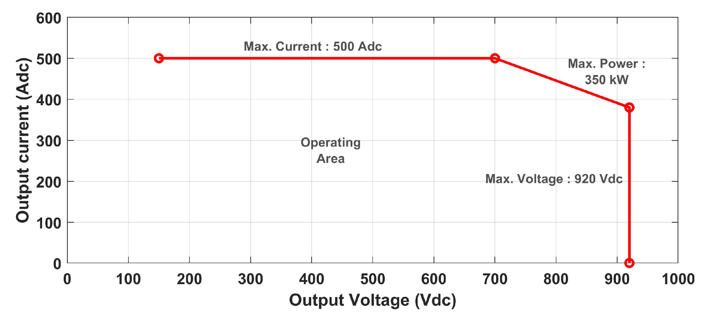
| Max DC output current (A) | 500 | 500 | 500 | 500 | 500 |
| DC output voltage (V) | 150–920 | Up to 920 | 150–920 | 200–1000 | Up to 920 |
| Max output power (kW) | 350 | 350 | 240 | 400 | 350 |
| Power factor | ≥0.97 | 0.98 | ≥0.99 | ≥0.99 | 0.99 |
| Current THDi (%) | ≤5 | - | - | ≤5 | ≤5 |
| Overall efficiency (%) | 95 | >95 | 95 | ≥95 | 98.5 |
| Ref. | Simulation Software | Simulation Parameters | Performance and Quality | Topology | ||||||||
|---|---|---|---|---|---|---|---|---|---|---|---|---|
| Output Power P (kW) | Input Voltage VAC (V) | Output Voltage Vdc (V) | Switching Frequency fsw (kHz) | Inductor L (µH) | Capacitor C1/C2 (µF) | 3θ-2L | NPC | Vienna | ||||
| [19] | PSIM | 50 | 400 | 800 | 100 | 500 | 3000 | Performance | Efficiency (%) | 97.87 | 96.20 | 97.14 |
| Total losses (W) | 1062 | 1896 | 1428 | |||||||||
| Input quality | PF (%) | 99.933 | 99.992 | 99.992 | ||||||||
| THDi (%) | 4.04 | 1.27 | 1.25 | |||||||||
| DPF | 1 | 1 | 1 | |||||||||
| Output quality | Low voltage ripple (V) | 3.40 | 4.81 | 1.99 | ||||||||
| Capacitor currents (A) | 43.6 | 47.1 | 42.7 | |||||||||
| [36] | PLECS | 22 | 400 | 800 | 20 | 750 | - | Performance | Efficiency (%) | 98.86 | 98.44 | 98.95 |
| Total losses (W) | 256.48 | 351.81 | 237.16 | |||||||||
| Costs (USD) | 343.34 | 456.76 | 385.8 | |||||||||
| [37] | MATLAB | 2 | 50 | 200 | 15 | 300 | 9020 | Input quality | PF (%) | - | 99.958 | 99.981 |
| THDi (%) | - | 2.87 | 1.94 | |||||||||
| DPF | - | 1 | 1 | |||||||||
| Topology of Converter | Voltage Ripple (V) | Current Ripple (A) | Efficiency (%) |
|---|---|---|---|
| Traditional DC-DC buck | 1.084 × 10⁻² | 1.196 | 98.99 |
| Two-phase interleaved DC-DC buck | 6.909 × 10⁻⁶ | 6.521 × 10⁻⁶ | 99.13 |
| Topology of Converter | PSFB | LLC |
|---|---|---|
| Efficiency (30% < SOC < 95%) | 94.43% | 94.20% |
| Losses (30% < SOC < 95%) | 118 W | 127 W |
| Frequency | 100 kHz | 100 kHz |
| Output filter capacitance | 200 µF | 1500 µF |
| Output filter inductance | 10 µH | - |
| Resonant capacitance | - | 54.5 nF |
| Resonant inductance | - | 46.6 µH |
| Ref. | Topology | Control Strategy | Simulation Software | Experimental Validation? | Objectives of Controller | |
|---|---|---|---|---|---|---|
| AC/DC Stage | DC/DC Stage | |||||
| [76] | NPC | DAB | PI | PSIM | No | (1) Ensure a power factor unity; (2) Absorb/inject a power current with a low THDi; (3) Regulate the current delivered to or from the battery according to its state of charge (SOC); (4) Adjust the difference between the DC voltage injected by the rectifier and the battery voltage. |
| [77] | Vienna | LLC | PI | - | Yes | (1) Neutral point potential balance of the rectifier; (2) Perform power regulation and power factor correction; (3) Frequency conversion and phase shift hybrid regulation; (4) Constant voltage and constant current controls of the LLC converter. |
| [78] | NPC | Three-phase Interleaved buck-boost | PI | Simulink | Yes | (1) Manage a fast charge/discharge; (2) DC voltage regulation; (3) Power factor grid correction. |
| [79] | 3θ-2L | Three-phase Interleaved buck-boost | PI | Unknown | No | (1) High power factor; (2) Voltage regulation; (3) Current limitation during the process of charging. |
| [80] | Vienna | DAB | PI | Simulink | No | (1) Safe charging of the BEV using CC-CV method; (2) Power factor correction; (3) Reducing the THDi to 0.79%; (4) Improve the efficiency of the charging system; (5) Large voltage range of the charger (48–600 V). |
| [81] | Vienna | LLC | PI | Simulink | No | (1) Excellent performance during CC-CV charging process; (2) Reducing the THDi to 3.12%; (3) Achieve good soft-switching. |
| Control Method | Robustness to Disturbance | Robustness to Uncertainties | Response Time | Algorithm Complexity | Main Characteristics |
|---|---|---|---|---|---|
| SMC | Good | Good | Fast | Medium | (1) Chattering problem; (2) The stability is ensured by using the Lyapunov function. |
| BSC | Poor | Medium | Fast | High | (1) The complex choice of coefficients; (2) The stability is ensured by using the Lyapunov function. |
| FBL | Medium | Poor | Fast | Medium | (1) The possibility of using linear control techniques; (2) Parametric variations cannot be controlled. |
| MPC | Medium | Medium | Normal | Medium | (1) Uses significant computing power; (2) Detailed description of the model. |
| FLC | Good | Poor | Slow | Medium | (1) Uses significant computing power; (2) Does not require mathematical model. |
Disclaimer/Publisher’s Note: The statements, opinions and data contained in all publications are solely those of the individual author(s) and contributor(s) and not of MDPI and/or the editor(s). MDPI and/or the editor(s) disclaim responsibility for any injury to people or property resulting from any ideas, methods, instructions or products referred to in the content. |
© 2023 by the authors. Licensee MDPI, Basel, Switzerland. This article is an open access article distributed under the terms and conditions of the Creative Commons Attribution (CC BY) license (https://creativecommons.org/licenses/by/4.0/).
Share and Cite
Saadaoui, A.; Ouassaid, M.; Maaroufi, M. Overview of Integration of Power Electronic Topologies and Advanced Control Techniques of Ultra-Fast EV Charging Stations in Standalone Microgrids. Energies 2023, 16, 1031. https://doi.org/10.3390/en16031031
Saadaoui A, Ouassaid M, Maaroufi M. Overview of Integration of Power Electronic Topologies and Advanced Control Techniques of Ultra-Fast EV Charging Stations in Standalone Microgrids. Energies. 2023; 16(3):1031. https://doi.org/10.3390/en16031031
Chicago/Turabian StyleSaadaoui, Achraf, Mohammed Ouassaid, and Mohamed Maaroufi. 2023. "Overview of Integration of Power Electronic Topologies and Advanced Control Techniques of Ultra-Fast EV Charging Stations in Standalone Microgrids" Energies 16, no. 3: 1031. https://doi.org/10.3390/en16031031