Abstract
The oil and gas business has high operating costs and frequently has significant difficulties due to asset, process, and operational failures. Remote monitoring and management of the oil field operations are essential to ensure efficiency and safety. Oil field operations often use SCADA or wireless sensor network (WSN)-based monitoring and control systems; both have numerous drawbacks. WSN-based systems are not uniform or are incompatible. Additionally, they lack transparent communication and coordination. SCADA systems also cost a lot, are rigid, are not scalable, and deliver data slowly. Edge computing and the Industrial Internet of Things (IIoT) help to overcome SCADA’s constraints by establishing an automated monitoring and control system for oil and gas operations that is effective, secure, affordable, and transparent. The main objective of this study is to exploit the IIOT and Edge Computing (EC). This study introduces an I2OT-EC framework with flowcharts, a simulator, and system architecture. The validity of the I2OT-EC framework is demonstrated by experimental findings and implementation with an application example to verify the research results as an additional verification and testing that proves the framework results were satisfactory. The significant increase of 12.14% in the runtime for the crude well using the proposed framework, coupled with other advantages, such as reduced operational costs, decentralization, and a dependable platform, highlights the benefits of this solution and its suitability for the automatic monitoring and control of oil field operations.
1. Introduction
The oil and gas industry is highly regulated and fund-intensive, so real-time monitoring, automatic alarms, and control of its asset operations are important for safety and efficient production. Many procedures are conducted in remote and different environments. The global demand for crude oil remains high, accompanied by high oil prices, which becomes a challenge to preserve crude production with minimum postponement []. Consequently, this study focuses on the crude oil production phase.
During an oil well’s life cycle, the major production is accomplished by natural lift (NL) or free flow and artificial lift (AL). Oil companies prefer not to use the AL for as long as NL is possible in the oil well life cycle. An oil well is NL when the natural reservoir pressure is great enough to lift the column of fluid from its origin to the surface (cheapest lifting cost); AL types are gas lifts, rod pumps, and submersible pumps []. More than 90% of all production oil wells require some form of AL []. Electrical submersible pump (ESP) oil producer wells represent 60% of the global crude oil production. The ESP lift will be the main target in the simulation and implementation phase to prove the worthiness of the proposed I2OT-EC framework.
The oil and gas sector has benefited greatly from cutting-edge technologies, including high-speed networks, mobile devices, data analytics, and artificial intelligence, to boost productivity and profitability, promote safety, lower environmental hazards, and improve operational reliability and security. Because of this, it is crucial for oil and gas businesses to operate their assets as efficiently as possible while maintaining safety [].
Generally, oil production plants have a huge quantity and wide dispersion qualities. As a result, manual data collecting is difficult and time-consuming. Additionally, manual data gathering is severely constrained because the pumping unit operates continuously around the clock. In brief, typical oil production plants use outdated information monitoring and management techniques.
SCADA systems and wireless sensor networks (WSNs) have been the principal remote monitoring and control tools utilized by the oil and gas sector throughout the previous few decades. SCADA’s data collection and transmission processes are either manufacturer-specific or industry-standard. RP-570, Profibus, Modbus RTU, and Conitel are examples of common historical SCADA protocols. Except for Modbus, all of these communication standards were developed by specific SCADA vendors but are now widely utilized. IEC 60870-5-101 or 104, IEC 61850, and DNP3 are industry-standard protocols. Many of these protocols also have TCP/IP extensions, making them more versatile []. The downsides of SCADA are the lack of object compatibility, high maintenance costs, the difficulty of upgrading equipment, and significant latency.
The ultimate goal is to monitor and manage the oil and gas production process to improve the production process’s reliability, availability, and dependability. As a result, there is a growing need for edge processing-based IIoT solutions to realize the intended requirements and avoid the disadvantages of legacy technologies. This study presents an I2OT-EC framework for monitoring and controlling oil field operations and equipment. The fundamental concept of the proposed architecture is illustrated in Figure 1, which enables timely data collection for remote conditional monitoring, the best control actions to reduce facility downtime, and machine-to-machine connections for increased automation and control. Although much work has been suggested in edge processing and IIoT, not much research has been performed on using an integrated edge processing and IIoT system in the context of oil and gas fields. As far as we know, this study is one of the few early attempts to utilize edge processing and IIoT in the oil and gas sector to achieve reliable, efficient, and secure remote monitoring and control oil field activities in an automated and effective manner.
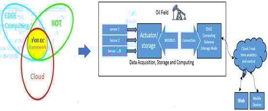
Figure 1.
The I2OT-EC framework diagram.
The contributions of this study are as follows:
- Introduce an I2OT-EC framework with system architecture and operational processes for remote monitoring and control in the oil and gas sector;
- Simulate and implement the system that verifies the I2OT-EC framework feasibility with real data in an oil field environment;
- Analyze the system’s dependability, stability, and security while outlining the benefits of edge computing and IIoT for remote monitoring and control in the oil field.
The rest of the paper is organized as follows. Section 2 discusses the background and related work. Section 3 explains the main methodology and the I2OT-EC system architecture, methodology operational flow, key framework components, and algorithms. The simulation of the I2OT-EC framework is presented in Section 4, along with further comments on the system analysis, and outlines the main components of the I2OT-EC framework. Section 5 presents the physical implementation for the proposed framework in a real oil ESP production well with a testing/verification approach and limitations. Finally, Section 6 provides the paper’s conclusion, summary, and future work related to this research. Before introducing the framework details, the list of nomenclature is displayed in Table 1.

Table 1.
List of nomenclature that is used in the whole framework.
2. Background and Related Work
The proposed framework suggests using a case study addressing forecasting equipment failures and planning proactive responses in electric submersible pumps (ESPs). In this case study, the machine learning algorithms needed much information from the primary ESP well design model to anticipate electric submersible pump (ESP) failures. Complex analytical algorithms must be used to assess a massive amount of regularly occurring operating data feeds from the ESP system to calculate the remaining pump’s lifetime. Computation is typically performed at the top end of the edge continuum. The ESP sensors’ data is used specifically to achieve the key objective and address operational issues. The background in details for edge computing, IIoT, and ESP is illustrated as follows.
2.1. Industrial Internet of Things (IIoT)
Integrating the Internet of Things (IoT) and its related technologies has been suggested to address several issues in various industrial sectors. Among these sectors, the oil and gas industry has been identified as one that can particularly benefit from the application of IoT, also referred to as the Industrial Internet of Things (IIoT). As cited in [], the implementation of IIoT in oil field operations offers several advantages, including real-time data collection, automatic alerts, remote monitoring, and control of machinery and processes. This reduces the need for human intervention in oil field operations and allows for effective automatic diagnosis and control of vital equipment and processes.
Examples of IIoT-based remote monitoring and control include monitoring pressure relief valves, tank levels, infrastructure, jet pumps, corrosion, wells, and pipelines, rotating equipment performance monitoring, and leak detection []. While most IoT systems are centralized, with IoT devices connecting to a centralized server to interact with one another, the centralized server can become a weak link in the system, leading to concerns about a single point of failure []. Given this, a decentralized system utilizing IoT is desirable to achieve a higher degree of trustworthy, autonomous monitoring and management of oil field activities. Interruptions to oil field operations can result in substantial losses in production and financial gains [].
The Industrial Internet of Things (IIoT) is the expansion and use of the Internet of Things (IoT) with intelligent sensors and actuators to improve industrial and manufacturing processes. IIoT, called industry 4.0 or the industrial Internet, uses the data that “dumb machines” have produced in industrial settings for years by utilizing smart equipment and real-time analytics. IIoT is based on the guiding principle that intelligent machines are superior to people at the gathering and interpreting of data in real-time and transmitting crucial information that can be utilized to make business choices more quickly and correctly [].
IIoT devices, IIoT gateways, and the cloud comprise the three levels of the IIoT system architecture. These IIoT devices are physical items with sensors and actuators that can exchange data via an edge gateway. The IIoT’s sensors can be chosen depending on what needs to be monitored. There are several temperatures, humidity, pressure, infrared sensors, and more [].
Modbus, WiFi, Bluetooth, ZigBee, and other technologies are frequently utilized in IIoT systems as communication protocols. The IIoT gateway is a more sophisticated computer device that connects to various IIoT devices and offers communications and data aggregation features, including data pretreatment, secure access to the cloud, and even edge analytics or fog computing. Table 2 illustrates the legacy technologies used in the oil and gas industry with their abilities and disadvantages.
Table 2.
A comparison between legacy technologies within oil and gas [].
Connected sensors and actuators enhance business intelligence initiatives by allowing the industry to identify inefficiencies and problems earlier, save time and money, and conserve resources. IIoT has many possibilities for industrial sustainability and quality control. Predictive maintenance (PdM), improved field service, energy management, and asset tracking in an industrial context are all made possible by IIoT. The Internet of Things (IoT) is a network of intelligent devices linked to create systems that monitor, gather, share, and analyze data. Each industrial IoT ecosystem consists of the following:
- Linked objects can perceive, transmit, and store their data;
- Infrastructure for public or private data connections;
- Programs that use analytics to create business intelligence from raw data;
- A place to save the data that the IIoT devices produce;
- People.
2.2. Edge Computing
Figure 2 depicts an edge computing asset that demonstrates how data was transmitted directly to the data communications infrastructure and then transformed into actionable data about how a specific piece of machinery was performing. This information may be utilized in the oil and gas business for preemptive steps to prevent production deferral, predictive maintenance, and machine operational mode optimization [].
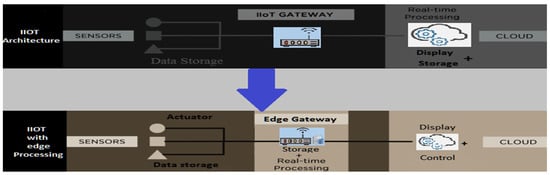
Figure 2.
Local real-time processing at the I2OT-EC framework.
The goal of an edge is to analyze data more quickly and in a larger volume near the point of generation, providing real-time action-driven outcomes. Running workloads within clouds is referred to as cloud computing, while doing so on edge devices is referred to as edge computing. In the monitoring framework, edge computing is recommended for handling time-sensitive data, whereas cloud computing is employed for handling data that is not time-driven. In remote areas (like oil and gas fields), when there is poor or no connectivity to a centralized site, edge computing is preferable to cloud computing in terms of latency [].
The concept of edge computing involves processing sensor data at the edge of the network, close to the source of data, rather than in the central nodes. This approach adopts a decentralized information technology network architecture that accommodates mobile computing and local data generation. The integration of edge computing adds an intermediate layer between IoT devices and the cloud, providing benefits such as improved processing speed, real-time decision-making, automatic alarms, and reduced complexity []. In the oil and gas industry, edge computing in conjunction with the Internet of Things (IoT) is utilized to:
Implement actions on data as close to the source as feasible rather than in a central location:
- Implement actions in real-time to minimize latency and reduce bandwidth usage;
- Suggest proactive actions.
2.3. Electrical Submersible Pump (ESP)
The most popular artificial lift technique for oil production, particularly for high oil producer wells, is an electrical submersible pump (ESP). Figure 3 illustrates the multistage centrifugal pumps that make up ESPs used in oil wells. Pumps extract oil from sub-hydrostatic reservoirs to boost output in wells constrained by inflow efficiency or tube pressure losses. Typically, the pump and motor are suspended from the production tubing. The pump discharges directly into the tubing, and the motor is positioned in a producing well underneath the pump [].
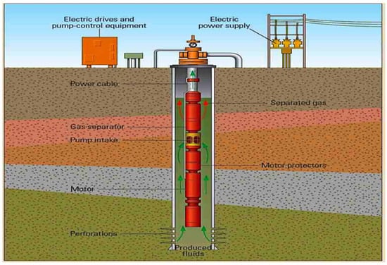
Figure 3.
ESP typical architecture diagram [].
An electrical power source, step-up transformers (to provide the necessary voltage), and a switchgear are the surface equipment needed for an ESP. Variable speed drive (VSD) or switchboard enables the equipment to stop and start. However, a VSD soft start drive is more effective in most operating cases to widen the system-operating range, adapt to working conditions, optimize performance, and apply physical constraints [].
Although experiments normally establish ESP performance curves, the head performance curve of the pump may also be calculated using analytical models []. Furthermore, the fact that the header rate and power rate functions may be fitted very precisely by the liquid rate, polynomial functions facilitate the application of pump performance curves in specialized computer programs.
The pump performance curves have a regular shape, making it possible for the formula, as mentioned earlier, to match them very closely with a maximum of eight to nine coefficients: N ≤ 9 and M ≤ 9 []. ESP engineering makes use of unique computer programs that make use of this function. With the help of an appropriate operational database for a pump, it can accurately explain the performance of various pumps. This database includes MOF (motor frequency), MOT (motor temperature), PIP (pump intake pressure), PDP (pump discharge pressure), and WC (crude water cut) to produce operational conditions to avoid pump breakdown and oil production loss. The pump must also be run within the recommended operating range (Figure 4) established by the two boundary rates (down thrust and upthrust limits) [].
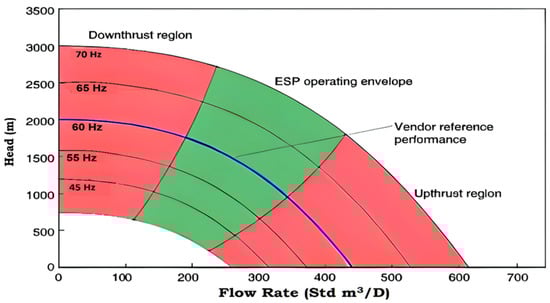
Figure 4.
Illustration of ESP operating modes [].
Mathematically, a pump performance condition (PPC) can be formulated as a tuple:
The PPC represents a set of pump performance conditions; all tuple parameters achieve a global view of the ESP downhole data to be used by the operator to ensure overall performance.
To provide some background, the researchers’ team visited Shell Egypt Company in the third quarter of 2021 (one of the largest companies in the oil and gas field worldwide). Such a visit was conducted to physically check the oil and gas production monitoring and control problems and to focus the research on the deficiencies before starting the I2OT-EC framework. In addition, the meeting was conducted with the production and reservoir engineering departments’ representatives. They confirm that the main problem of production monitoring and control usually exists in crude oil production wells, especially high-producer wells that use ESP as an artificial lifting method. An ESP department representative was invited to attend the meeting and confirmed in brief that most ESP wells have primarily employed wireless sensor networks and supervisory control and data acquisition (SCADA) systems. SCADA is not scalable (inability to expand equipment), with high maintenance costs and high latency [].
Therefore, we decided to use such points as a key for the I2OT-EC framework to solve the deficiencies mentioned above through IIoT and edge computing. We briefly explain the directions in the framework to assist in solving such problems in the oil production monitoring; also, the representatives of the departments showed their commitment to delivering practical support for our research that can help them to solve problems in the land. Initially, our researchers’ team asked the departmental representatives to obtain an operational database for a real ESP oil well and support our research to verify the I2OT-EC framework by agreeing to make a complete real implementation in an actual oil field environment.
The objective is to conduct oil field control and monitoring conditions (a set of measurement values) that will be used in the simulator to generate automated operational massages in a dedicated log. Furthermore, such a group of oil field control and monitoring rules is programmed in the simulator that will be the backbone for the framework’s real implementation. The main goal is to determine proactive actions and ESP predictive maintenance precautions to avoid pump breakdown and oil production loss (which will be discussed in detail in the simulator section). Then the implementation of the same ESP oil well that the operational database supplied will verify the I2OT-EC framework.
2.4. Related Work
Many applications’ dependability, efficiency, reliability, and security might be greatly enhanced by integrating IIoT with edge computing. The state-of-the-art research connected to this topic is covered in this section. The emphasis is on IIoT and edge computing technologies and their applications across various industries, particularly in the oil and gas and closely linked energy sector.
In order to develop an edge computing system that can send out early warning messages, Christos Spandonidis [] conducted a study based on data gathered from an intelligent wireless system for leakage detection in pipelines for the transportation and storage of oil and gas. The main challenge for this arrangement was the significant amount of background noise in the measurements. In addition, the background noise caused outside noise to infiltrate the monitored system, potentially lowering its ability to identify signals accurately.
Hutama Arif Bramantyo [] implemented a study that has shown that data-driven soft sensors are used to monitor an oil and gas refining facility. The method might help plant operators forecast variables more accurately. Modern machine learning techniques, large data processing tools, and cloud computing innovations are highlighted by the platform for in-process data analytics. The design comprised a combination of proactive maintenance, which required taking care of individual pumps based on previous usage trends; scheduled maintenance, which involved conducting updates on a regular schedule; and reactive maintenance, which involved responding to an emergency asset failure.
A novel approach for choosing the ideal repair order in the marine sector was developed by PNV Srinivasa Rao []. Proactive and predictive maintenance can improve reliability and availability and save time and money. This study concentrated on the service for a vessel maintenance depot. The different nature of the repair and maintenance activities was a constraint on applying the smart factory concept in production. By combining the aforementioned with an IIoT-based application that automatically gathers and elaborates data, the reliability and criticality based maintenance (RCBM) method may be enhanced. According to the experimental findings, the IIoT with predictive maintenance-as-a-service (PdMaaS) improves fuel economy (98.5%), delay time (38.5%), organizational processes (98.5%), resource management (92.1%), and predictive maintenance in shipbuilding (96.9%) for a total proportion of AI (98.7 percent).
A secure and intelligent communication system for IIoT-enabled pervasive edge computing (PEC) was proposed by Fazlullah Khan []. IIoT devices used a simple detection technique to find the Sybil devices. As a result, their secret identities were revealed to the neighbors and edge servers. According to the findings, a system of this type was resistant to Sybil’s attack. The suggested approach depended on edge computing, artificial intelligence-based optimal setup, and Sybil attack detection. A parallel artificial bee colony (Pabc) technique was used at the edge server to configure IIoT devices in the best possible way. According to the findings, a system of this type was resistant to Sybil’s attack in terms of accuracy, sensitivity, specificity, and detection rate. Additionally, it improved the network’s quality of service (QoS) and had better convergence curves than the methods currently used for several benchmark functions.
Bartosz Boguslawski [] allows IIoT edge analytics to improve artificial lift systems through automated dynagraph recognition by intelligence running on the remote assets. Furthermore, it enables autonomous diagnostics and operations through a unique set of smart machine learning techniques and edge architecture. As a result, a high level of asset management is possible even with a limited workforce.
Wazir Zada Khan [] proposed the importance of continuously monitoring various operations of the oil and gas industry’s upstream, midstream, and downstream sectors. A generic IIoT architecture could produce smart oilfields by improving accuracy and giving real-time monitoring during abnormal conditions. The suggested architecture consists of three modules: a smart object module, a gateway module, and a control centre (server) module. Each module addressed a specific purpose to assist in monitoring the linked oilfield environment and layered in sensing, networking, and application layers. However, the disadvantage is that it was not possible for direct applicability due to the generic proposed architecture.
An IIoT-based architecture was presented by Rashid G. Alakbarov [] for simple, secure, dependable, and quick data collecting from sensors installed in the oil and gas industry. A study is being conducted on managing oil and gas platforms using various wireless sensor networks. Processing sensor data opens up new possibilities for enhancing oil platform (deposit) safety, operations optimization, problem prevention, troubleshooting, and lowering exploitation costs in the oil & gas sector. The study also examines the security concerns related to the various IoT architectural monitoring system tiers. New data security and safety challenges are anticipated with the expansion of wireless sensors and sensor data exploitation.
Jianhou Gan [] took the coking process as the research subject and proposed an intelligent monitoring network based on networking technology. Building a perception layer network and relying on a ZigBee mesh clustered network should be the main goals when creating a coking process intelligence-monitoring network. Additionally, it proposes a network routing setup and a data transfer method. The vast application of the IIoT in the intelligent management and monitoring of the metallurgical process is greatly facilitated by this study, which serves as a useful reference.
A user-controlled smartphone IoT-specific controller and integrated BLE 4.0 were proposed by Won-Seok Choi [] for an oil skimmer monitoring system. The IoT’s open source hardware (OSHW) trend is its device hardware. This makes free design content available for tangible objects and free and open-source software (FOSS). The majority shares and develops it due to the ecosystem created by the derivation of open-source culture. The approach used in this study allowed users to track the analog and digital data received from the peripheral circuit in real-time using existing applications. The restriction only permits monitoring of oil skimming through mobile phones.
N. Kumaran [] focused on the project (using the ThingWorx platform), which is an IoT mobile and cloud-based platform. This project was developed to verify the working condition of the heat pump; a heat pump is an embedded device that may be present at a remote location and mainly in industry. The two major challenges are continuous monitoring and cost. The ThingWorx platform is connected to the pump to send and receive data, containing the sensors from which the data are transmitted through HTTPS. ThingWorx is the complete development of the IoT platform mainly designed as a cloud (server) to store data from the embedded system that uses sensors for exchanging data. The main aim is to verify the working condition of the device in real-time.
With the use of the Internet of Things for measurement and control, Shengquan Yang [] created a gasoline pump system. The IoT perception, network, and application control layers are discussed. The authors also discuss the control theory of the sensor and aggregation instrument nodes. In the end, the main design software module content of the IoT center computer is represented and suggested, together with the programming flow diagram for the node microcontroller. The outcome of the enterprise experiment indicates that the system has benefits over conventional manual inspection techniques of the petroleum well fuel pump, including ease of operation and maintenance, low labor intensity, high measurement/control efficiency, and high precision. However, the system needs to be upgraded even though the users have approved these findings.
The IoT was the main focus of Jinfeng Sun’s [] research on identifying and tracking anomalous noise and vibration. This study also looked at the different types of crude oil theft, the challenges associated with oil anti-theft detection systems, and the requirements assessment for the IoT application. Finally, the authors covered the IoT-based intelligent anti-theft system for crude oil pipelines and tank trucks. Additionally, the difficulties associated with implementing an anti-theft system are examined, and recommendations and counsel are offered to ensure the system can be properly implemented. The use of IoT has the benefit of enhancing communication between intended parties and oil anti-theft systems. The study’s focus on China prevented it from considering scenarios and circumstances involving international security and privacy that are seen as a constraint for this system.
A model predictive control (MPC) system, which allows a process to function by making a series of predictions about its potential inputs and outputs, was optimized by Carlos A. Garcia []. As a result, a Raspberry Pi 3B development card can fully operate a programmable logic controller (PLC) using a control function developed under the IEC-61499 standard. It combined the physical advantages of a PLC with the computational power of an embedded controller throughout the operation, which involved the pump control of an oil pipeline pumping station.
A remote smart oil pipeline surveillance system (SOPSS) with the capacity to detect and report pipeline vandalism actions before their occurrence by SMS, email, or phone call was described by Laith M. Fawzi []. A video camera was coupled with the system software to record video and monitor unusual occurrences. The results show that the system can monitor and report in real-time, using only 97% of the available data. This will raise bandwidth utilization to 96%. As a result, the suggested method is effective for various monitoring objectives.
William G. Elmer [] attempted to answer questions about how the Internet of Things is utilized at a well-producing location, how various operations personnel could potentially benefit from these applications, and gave specific examples that apply to artificial lift equipment. These examples only scratch the surface of the possible applications and aid in conversations about the place for this technology and help promulgate new applications. Such a study shows that IoT devices with advanced math capabilities allow engineering calculations and statistics to improve equipment operations and create KPIs and other valuable diagnostic indicators.
Abel Avitesh Chandra [] found a solution to the on-site monitoring and control of diesel generators using online tracking to observe fundamental characteristics of a running diesel generator utilizing widely accessible resources that are also inexpensive to set up and maintain. The project looked into using the IoT platform, a flexible technology that interacts with both things and the environment in the digital age. This research investigates the monitoring and management of a generator utilizing the Internet of Things paradigm. The ThingSpeak sensor cloud is a free and effective solution for IoT applications. Preprocessing and predictive analytics may be applied to IoT data by the service, which is run by Mathworks and enables Matlab’s sophisticated analytical tools to be integrated into ThingSpeak. Such characteristics would allow the cloud service to give users a wide range of possibilities in interacting with everyday connected objects.
Using an IoT controller as the foundation, Kirit R. Bhatt [] created a wireless data capture system that will be smaller, cheaper, and more capable of high-speed data transfer while using less power. In real-time, approximately ten thousand pumps (parallel pumping system) will be mounted in any industry or firm, so it is not easy to control and monitor these pumps using manpower or any other devices. To monitor these pumps, this system will use WiFi technology and the MQTT (message queuing telemetry transport) protocol to transfer data to the cloud. Such a protocol is a broker-based publish/subscribe messaging mechanism. It is also open, straightforward, lightweight, and simple to use. Due to these qualities, it is best used in contexts with restricted resources, such as when the network is costly, has little bandwidth, or is unstable when running on an embedded device with constrained CPU or memory capabilities.
The NGS-Plant One system, demonstrated by Federico Civerchia [], is a sophisticated IoT monitoring solution created specifically to enable advanced predictive maintenance applications. A practical test using actual IoT sensor devices put in an energy power plant was used to assess its effectiveness. The performance findings measured in terms of latency and power consumption demonstrate that each node is available using only IP-based techniques with a tolerable delay. The operation period of the suggested system may also be extended to many years (for example, one year with a transmission rate of 30 min), demonstrating its viability and advantages in an industrial environment.
A multiphase flow monitor of the LC-40DR-A type was employed by Hanyue Zhang [] as a remote data acquisition terminal. The three main areas of emphasis are data gathering, administration, and application. The GPRS network serves as the data transmission medium, and information management software is used as a data visualization tool. The solution accomplishes the digitalization of the industrial facility, boosts productivity, and lowers downtime and equipment failure. This can be achieved by implementing real-time monitoring, automated alerts, user management, report management, and equipment management.
Edurne Irisarri [] works on remote monitoring challenges of the oil production process. A general strategy is put out that enables remote access to process data and achieves vertical integration from business units to the production level. This contributes to applying unique meta-models based on industrial standards (ISA 95 & ISA 88) established for the production process and information supplier devices.
The IIoT has many challenges in different fields, as described previously. These challenges include real-time monitoring, low-cost implementation, speed processing, data safety, and security. Table 3 compares the various studies based on certain attributes, such as targeted area, proposal type, technology, accuracy, date, and results. The second criterion indicates the styles of the proposed method (architecture, system or project, etc.). The criterion of accuracy denotes how the proposed approach or architecture monitors and manages the intended targeted area. The last criterion is whether the proposal results in a level for the user that is either satisfactory or provides limited satisfaction. This could help to conduct our research’s intended direction and avoid the drawbacks of previous work.
Table 3.
Summary of related works.
3. Methodology
The primary objective of this study is to introduce the I2OT-EC framework system architecture and operational processes for remote monitoring and control in the oil and gas sector. To verify the feasibility of the framework, the system was simulated and implemented using real data in an oil field environment. This was done to analyze the system’s dependability, stability, and security and to outline the benefits of edge computing and IIoT for remote monitoring and control in the oil industry. The methodology for implementing the system is outlined in Section 3. The first step in this process is to present the framework architecture’s primary layers, followed by a description of the overall architecture (Section 3.1). Subsequently, the methodology for oil field monitoring and control is detailed in Section 3.2. The proposed framework’s center comprises the IIoT and edge computing subsystems.
3.1. High-Level System Architecture
The proposed framework architecture can be divided into three layers (as illustrated in Figure 5A), including the device layer, I2OT-EC layer, and cloud monitoring and design layer as the following:
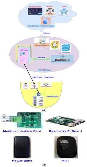
Figure 5.
(A): a novel IIoT architecture based on I2OT-EC. (B): an overview of the IIoT edge computing subsystem.
A. Device Layer: consists of numerous IIoT devices, such as an electrical submersible pump and associated sensors capsulated in the downhole pump assembly (temperature sensors, pressure sensors, frequency sensors, etc.). This layer is responsible for connecting the physical world and the digital world. In addition, it mainly undertakes two functions. One is to collect and transfer the data to the upper layer, and the other is to execute the commands sent from the upper layer connected through the ESP power/control cable.
B. I2OT-EC layer: such a layer consists of:
- Variable speed drive (VSD) with computer-aided system and storage capability), which acts as the main actuator for the ESP and is connected by a Modbus link.
- The IIoT edge computing subsystem contains a Raspberry Pi board, Modbus interface board, MIFI (standing for “my WiFi,” which is a mobile hotspot device), and power bank, as illustrated in Figure 5B. The Raspberry Pi board with data storage capability is the heart of the system, as is the system’s main controller []. The whole subsystem acts as a gateway that connects such a layer to the upper layer through the Internet. Therefore, data/operational database storage is redundant in both VSD (in the lower layer) and the Raspberry pi board (in the current layer).
This layer integrates communication, computing, and storage capabilities. The main function that the I2OT-EC layer undertakes is the real-time input for all information on oil field activities, including the equipment’s working conditions and the operating parameters of the oil well, pump, and sensors, which can be gathered and analyzed in real-time processing. The real analytics conducted by such a layer also proposed proactive actions and an automatic alarm log that minimized the production loss and maximized the assets’ lifetime.
C. The cloud monitoring and design layer consists of the servers and the enterprise control system. This layer is responsible for monitoring and controlling the ESP remotely through the industrial dashboard introduced by the cloud as an enterprise control system. The layer conducts its function under the authority of the preprogrammed monitoring and control procedures introduced by the proposed framework (such programmed procedures and algorithms with their flowcharts will be explained in detail in the simulator section).
The board used is a Raspberry Pi 4 Model B with a 1.5 GHz 64-bit quad-core ARM Cortex-A72 processor, onboard 802.11ac WiFi, Bluetooth 5, full gigabit Ethernet, two USB 2.0 ports, two USB 3.0 ports, 2 GB of RAM, and dual-monitor support via a pair of micro-HDMI (HDMI Type D). The Pi 4 is powered via a USB-C port, providing additional power to downstream peripherals. Unfortunately, the Pi can only be operated with 5 volts and not 9 or 12 volts like other mini-computers of this class []. Based on the distinctive characteristics of oil field operations, the IIoT edge computing subsystem introduced as the gateway to the cloud configuration was made, which is best suited for an oil field operation with a medium or large scope. Furthermore, due to the comparative computing capabilities of IIoT devices, IIoT gateways are better equipped to preprocess IIoT data and take part in real-time analytics. At the same time, the whole dashboard display and decision-making will be presented in the cloud layer.
3.2. Methodology Operations Procedure
The IIoT/EDGE computing system methodology offers a dependable decentralized platform for data interchange and redundant storage in both the IIoT actuator and the edge-computing gateway, as illustrated in the sequence diagram in Figure 6. The following stages outline the sequence of events for the smart dashboard control system, cloud server, redundant data storage, gathering data, and data processing for IIoT in oil fields.
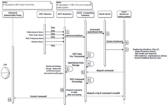
Figure 6.
Sequence diagram of IIoT/edge data collection and processing (numbering from 1 to 11 refers to the steps described below).
Step 1. IIoT sensors A, B, and N regularly deliver measurement data regarding ESP operations to the selected actuator.
Step 2. The IIoT actuator (VSD with a pre-computer aided system) receives and collects the measurement data, stores it in a local storage drive, displays it at the VSD local monitor, and sends it with a continuous update for the EDGE gateway every 5 min.
Step 3: The EDGE gateway performs actions on the data, such as data aggregation, formatting, time stamping, and even simple trend analysis during preprocessing (advanced data analysis to identify potential issues).
Step 4. The EDGE gateway packs the relevant data in an appropriate format and stores it in an Excel sheet as it updates the database.
Step 5. The EDGE gateway sends the processed operational data to the cloud server.
Step 6. The smart dashboard periodically retrieves IIoT data from the cloud server.
Step 7. The smart dashboard makes a visual display for:
- All processed operational data in curves and values form;
- The display log of:
- ○
- Smart proactive actions and an automatic alarm generated by the system to optimize pump operation that needs user approval for execution;
- ○
- Proactive maintenance precautions for safe and continuous ESP operation to avoid operational failure.
- Log for user actions feedback performed by the user.
Step 8. When the user approves a command action, it will be dispatched to the EDGE gateway.
Step 9. The EDGE gateway retrieves the command action from the received transaction and repacks it into a format that the IIoT actuator can interpret and implement.
Step 10. The EDGE gateway sends the command to the IIoT actuator (the command is processed and implemented if valid, otherwise, log feedback is sent to the dashboard that the command is invalid).
Step 11. The IIoT actuator will send actionable commands for pump maintenance, repair, and optimal operation to carry out the actions on the ESP.
4. Experimental Results
This section discusses the I2OT-EC framework simulator. First, the overall system analysis for the main components of the simulator is presented, including the server side, Modbus connection, client-side, cloud side, and the intended algorithm. Then, the focus will be on the IIoT and edge-computing subsystems, as these are the foundational elements of the I2OT-EC framework. Finally, the I2OT-EC framework demonstrated how it could be used for oil field monitoring and control using the case studies from []. The oil field operating safety, dependability, revenue gain, cost reduction, and those quality attributes succinctly summarize the framework’s main benefit, which will be illustrated in detail in the implementation section. The case study presented in the simulator and the implementation phase is to monitor and control an ESP oil well located remotely in an onshore oil field.
The simulator program is developed using python language. The analysis of enormous volumes of process data, recording data through a Modbus communication link, and preventative maintenance are all common industrial automation activities that python handles easily. Furthermore, due to its Bluetooth and wireless LAN capability, the Raspberry Pi board is utilized as the IIoT gateway since it allows for the simultaneous connection of several sensors. The Raspberry Pi also features a 40-pin GPIO (General Purpose I/O) connection for connecting with external sensors.
In the used case study, as per Figure 7 (the simulator architecture diagram), the Modbus is used to extract data from the actuator via the Raspberry Pi 1 (server/variable speed drive VSD with storage capability). Then the data is sent to the smart edge computing/storage gateway assembled as Raspberry Pi 2 (Referred to as client/gateway). The client will send this data to the cloud server to display the dashboard and control the well. In addition, the user can send a control signal from the cloud (i.e., change the ON/OFF status and change the frequency), then the Raspberry Pi 2 receives this signal that is processed and sent to the actuator (Raspberry Pi 1).
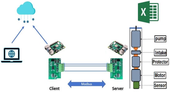
Figure 7.
Simulator architecture diagram.
4.1. System Analysis
This section presents the detailed system analysis for the simulator, which includes the server/VSD side, Modbus connection, client side, cloud side, and the main algorithm.
4.1.1. Server/VSD Side
In our case, we read data from an entire operational database Excel sheet for the intended ESP that the implementation will be conducted to it.
From Table 4, the obtained data is as follows:
Table 4.
A portion of the real operational database excel datasheet.
- MOTOR TEMP: ESP motor temperature;
- PDP: pump discharge pressure;
- PIP: pump intake pressure;
- RUN FREQ: ESP motor frequency that changed/controlled locally by the VSD;
- RUN STATUS: when ESP is ON, RUN STATUS = 1; when ESP is OFF, RUN STATUS = 0.
The Excel datasheet is real operational data from the crude oil well equipped with ESP as a part of the I2OT-EC framework operations, and the file was downloaded from the VSD that controls the downhole ESP of such a well. Figure 8 (Server flowchart) concludes the server/VSD side function as follows:
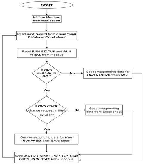
Figure 8.
Server flowchart.
- Reading and filtering the data from the Excel sheet.
- Send this data to the client side via Modbus.
- Receive and process the signal from the client to control the ESP with the following commands:
- Changing the frequency
- Changing the ON/OFF status for the ESP.
- When receiving a specific value for the frequency, the server/VSD verifies if this frequency exists and obtains the data accordingly.
- When receiving an action for changing status to OFF, the server/VSD verifies the last OFF status and obtains its corresponding data.
4.1.2. Modbus Connection
In Figure 9, two Modbus RS-485 HAT shields are used for the Raspberry Pi for the connection between the server side and the client side (one on the server/VSD side and the other for the client–server/VSD).
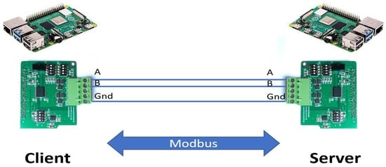
Figure 9.
Modbus communication between the client and server.
Client side: On this side, the Raspberry Pi receives the extracted data from the server/VSD side via the Modbus and sends specific information to the user cloud interface; the main objective of this side is as follows:
- Receive a control signal from the client in case the user wants to control the ESP with the following commands:
- ○
- Changing the frequency
- ○
- Changing the ON/OFF Status for the ESP;
- Receive the following data from the server/VSD side via the Modbus (MOTOR temperature—PDP Pressure discharge—PIP Pressure intake—Running Frequency -Running status);
- The client/gateway side sends the above-received data to the cloud;
- The client/gateway side conducts the conditions (by using the equations and ESP performance curve introduced in the Background section that is used as input to a detected Shell software program for the ESP modeling and design that outputs such conditions), which creates a messages log with:
- ○
- The needed proactive actions (automatic alarms) to optimize the pump operational mode;
- ○
- The needed predictive maintenance (PdM) precautions for safe and continuous ESP operation to avoid asset failure.
Such conditions will be clarified in the client flowchart (Figure 10) as the following: Note: frequency change step with 0.1 ranges from zero to 65 Hz only.
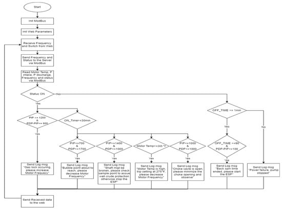
Figure 10.
Client/gateway flowchart.
These conditions were conducted based on reservoir analysis and the ESP manufacturer performance curve (in cooperation with the petroleum and reservoir engineering team). This ensures that the pump works in the recommended optimum operating range defined by the two boundary rates, as seen in Figure 4 (down-thrust and up-thrust limits).
Cloud side: The Adafruit IO displays the dashboard in this section and sends a control signal to the client. Adafruit.io is a cloud service that can connect over the Internet to send and retrieve data and provide a display dashboard that allows for charting, graphing, gauging, and logging the needed data, as in Figure 11.
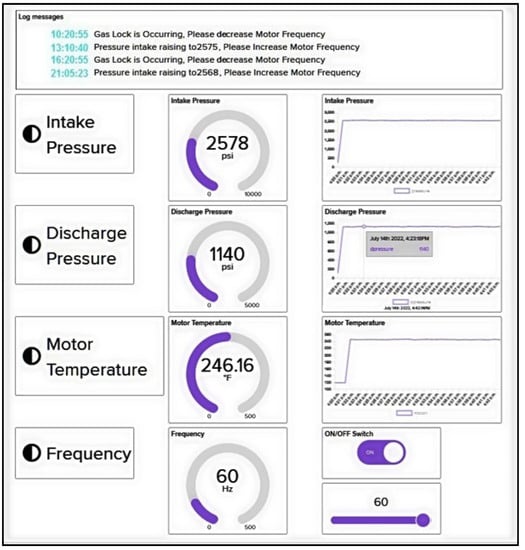
Figure 11.
A snapshot of the whole simulator dashboard.
4.1.3. Algorithm
The simulator algorithm of the I2OT-EC framework for smart real-time crude oil production monitoring and control (SRTPMC) is codded in python and illustrated in Algorithm 1.
| Algorithm 1: I2OT-EC framework for the SRTPMC algorithm. |
Temp,PIP,PDP,Freq,Status ← Receive_Modbus() Status_Value ← Receive_web(Switch) Freq_Value ← Receive_web(Frequency) If (Status_Value == “ON”), do If (PIP >= 1200 & (PDP-PIP<=600)), do Log msg "Lock occurring, please increase freq." else if (ON_Time>= 30 min), do if (PIP<=700 & PDP>=1700),do Log msg "Bubble point about to reach, decrease freq." else if (PIP>=1400 & PDP<=1000), do Log msg "Shaft might be broken; please check sample point to assure well crude protection; otherwise, stop the ESP." else if(Motor_Temp >= 265), do Log msg "Motor temp is high, trip setting at 275F, please decrease freq." else if(PIP<=1000 & PDP <=1000), do Log msg "Choke valve is open; please minimize the choke opening and observe." if(Status_Value == “OFF”), do if(OFF_Time>= 1 min), do if(OFF_TIME >= 90 min & PDP-PIP <=100), do Log msg "Backspin time ended; please restart the ESP." else, do log msg "Power failure, the pump stopped" function Receive_Modbus() if(serial available), do Received_data ← Temp,PIP,PDP,Freq,Status function Send_Modbus() if(serial available), do Transmit_data ← Frequency, Switch status |
5. Framework Actualization and Proofing
This section discusses the I2OT-EC framework implementation. First, the overall system implementation overview for the main components of the I2OT-EC framework (Section 5.1) is presented. Then the testing and verification of the implementation using Adafruit IO [] (Section 5.2) is reviewed. Next, we discuss the limitations of the system (Section 5.3). The focus will be on the IIoT and edge-computing subsystems, as these are the foundational elements of the I2OT-EC framework.
5.1. Framework Implementation Overview
The framework simulator forecasts the system operation state on short- and long-time scales based on the current operation state and user orders via the industrial control dashboard. The simulation outcomes are subsequently communicated to the users, creating a complete information loop. Furthermore, the simulator defines the thresholds and prohibited operating areas in advance, reducing fault demands and enhancing the system dependability. The digital simulator has been identified as a vital component of the proposed framework, providing interactive and safe system manipulation. A real implementation was conducted on the ESP oil well after fine-tuning the simulator by adjusting and rectifying all the outputs to the framework needs. The operational database has been used in the simulator architecture to have a non-doubt experiment with a real example for validating the proposed framework.
The research team traveled to the western Egyptian desert for the intended oil fields. First, a meeting was conducted with the field manager, production manager, maintenance manager, and ESP supervisor to double-check and review the plan for the implementation procedure and its steps. After that, the research team, under the supervision of the field production crew, ESP crew, and maintenance crew, conducted the real implementation. After that, the well stopped for 2 h (the ESP backspin period) to disconnect the SCADA system and install our system. As agreed, such implementation monitored and controlled the intended ESP for one month (throughout May 2022) through the cloud layer using the industrial control dashboard in coordination with the field ESP team. In addition, inputs and outputs for our system were monitored 24/7 during an agreed period.
At the end of May 2022, the well stopped again, and we dismantled our system from the well location. A meeting was conducted again with the field focal points. The field focal points appreciated our effort per the trial’s results recorded and analyzed during the period. The results analysis shows excellent performance for our system (compared with the SCADA system that monitored and controlled the ESP before our trial three years ago). The results initially show good progress (minimizing the pump downtime, minimizing oil production deferment, etc.) that will be illustrated in-depth in the next section. Figure 12 shows our framework implementation overview, which is identical to the simulator architecture in consideration of the following:
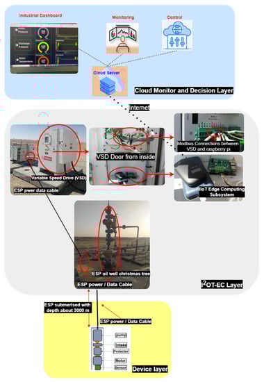
Figure 12.
I2OT-EC framework implementation overview.
- The device layer includes the ESP pump (including sensors) that exists downhole with a depth of about 3 km.
- The power/control cable connects the ESP to the step-up transformer (in the I2OT-EC layer), which feeds the VSD.
- The IIoT edge computing subsystem is equipped inside the VSD to:
- ○
- Present good ventilation through the VSD ventilator;
- ○
- Minimize environmental hazards that can affect such devices, such as direct sunlight, sandstorms, and high temperature (since the well is located in the desert);
- ○
- Electrical power supply for the subsystem.
- The IIoT edge computing subsystem contains a power bank powered by the VSD. In the case of a power generator failure, the power bank is capable of supplying power for the Raspberry Pi board and the MIFI for at least 12 h to secure:
- ○
- The data availability for the control centre at all times;
- ○
- A healthy shutdown for the IIoT edge computing subsystem.
- The IIoT edge computing subsystem is connected to the Internet through the MIFI device to reach the cloud layer.
- The IIoT edge computing subsystem includes the Raspberry Pi board connected to the VSD through MODBUS Serial (RS485 type). The VSD registers are mapped to connect through MODBUS, and such registers are numbered differently from one sensor manufacturer to another. Triol, CGS, Zenith, and Oxford are the most well-known sensor manufacturers. However, any sensor manufacturer can use the framework implementation because the programming code for such MODBUS connections, including the register mapping, was programmed.
5.2. Results and Discussion
The simulator is programmed based on the use case study and the implementation was tested on Adafruit IO [], a platform designed to display, respond, and interact with IIoT and edge project data. Adafruit IO provides a cloud service that runs the needed task, therefore we do not have to manage it. We can connect to it over the Internet, where data is kept private and secure.
In implementing the intended case study, the IIoT gateway gathers information about the IIoT measurement values of the ESP well. Then, it sends it to Adafruit IO via a transaction. Adafruit IO visualizes the data measurements inside an online IO dashboard. It enables one to chart, graph, measure, log, and visualize the data using dashboards, a tool included in Adafruit IO. By default, dashboards on Adafruit IO are set to private and secure, validating the I2OT-EC framework security concerns. Adafruit IO displays the dashboard and provides the needed controls per the log recommendations tested by Adafruit IO, as per Figure 13.
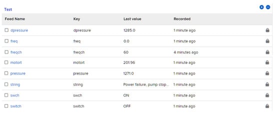
Figure 13.
Snapshot for the framework implementation events as a test.
The figures above prove that all the sent data and need control actions have been conducted in real-time through the real implementation as per the last test conducted on 31 May 2022.
Figure 14 shows the well stop log for our case study, with a big increase equal to 12.14% (the difference between the two runtime values shown in Figure 13, 99.93% in the right picture vs. 87.79% in the left picture) in the runtime for the well using the framework implementation conducted in May 2022 than the SCADA system in April 2022. The downtime in SCADA has various underlying causes connected to operational circumstances, such as gas lock, pressure intake, high-pressure intake, etc. However, one of the most significant benefits of our system is that it implements proactive alarms for such situations that can also advise the necessary action and can be carried out remotely to prevent time loss, as shown in Figure 11. The proactive actions executed per the log system advice led to minimizing the pump downtime, minimizing oil production deferment, and maximizing the pump’s lifetime. In contrast, SCADA lacks an intelligent, proactive system that causes such shutdowns.
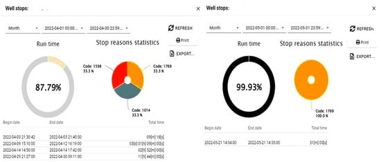
Figure 14.
Snapshot for the well stops log for April 2022 using Scada and May 2022 using our framework implementation.
The EDGE computing subsystem processes the data and determines the proactive actions needed for the current oil field operating situation. The output actions include “power failure, the pump stopped”, “backspin time ended, please start the ESP”, “Gas Lock Is Occurring, Please Increase Motor Frequency”, and “bubble point about to reach, please decrease Motor Frequency”. In addition, The EDGE computing gateway generates action commands as an output to be executed by the IIoT actuator (VSD). As a result, remote oil field operations can be automatically managed with little human assistance. Finally, it is clear from the preceding that the I2OT-EC framework offers reliable and automatic monitoring and control for oil field activities. The following are the principal advantages that the oil sector can derive from our framework:
- Real-time data processing and automatic control: As an expanded application of the IIoT, edge computing may automatically carry out the oil field management rules by examining the IIoT measurement results and making the appropriate decisions. In addition, the system can regulate activities in real-time and achieve timely monitoring of oil field operations and equipment, including pump operation monitoring, intake & discharge pressure, motor temperature, and well equipment concerns. This will lead to little human involvement in the automated control of remote oil field activities.
- Elimination of central administration: No central server or administration is required to manage oil field operations or carry out remote monitoring, thanks to the deployment of IIoT and edge computing nodes. Our system is distributed (processing and storage are redundant in both the smart actuator and EDGE gateway). As a result, efficiency would increase, and a single point of failure of the central server (frequent in traditional IoT and SCADA systems) would be avoided with edge transactions.
- Data/transaction translucence and traceability: Transparency is provided via the cloud. Every oil field monitoring and control transaction is logged, saved, and assigned to the individual entity that submitted it (as per Algorithm 1). The logged transactions and events can be utilized to recreate oil field activities for further investigation and analysis in the event of an incident or performance review. Furthermore, traceable data provide a reliable source for oil field operators and management to detect and trace problems back to their causes and origins.
- Platform with a high degree of trust: A trust mechanism for transactions between the parties was provided using our cloud and edge processing. Transaction records are replicated throughout the whole network’s cloud.
- Cost savings: Because IIoT and edge computing infrastructures do not require the involvement of any third parties, their operating costs are minimal. Additionally, edge computing and cloud utilization offer automated data processing and decision-making based on predefined conditions. By doing away with many labor-intensive manual tasks, operating expenses are further decreased. As a result, an IIoT/edge-based system may drastically lower costs compared to the conventional oil field remote monitoring and control solutions, which are vital for the oil and gas business. Table 5 compares the I2OT-EC framework against established remote monitoring and control solutions for oil field operations.
Table 5.
Overview of the comparison of the I2OT-EC framework against conventional remote monitoring and control solutions for oil field operations.
Finally, the results were overall satisfactory for the wells operation crew compared to the SCADA system. However, the implementation still needs some improvement regarding the hardware that needs to be encapsulated in a single body, including a ventilation facility for the mainboard. In addition, electrical metrics were to be added to the dashboard, and proactive tips needed to be introduced to the smart system on the software side to minimize electrical blackouts. Such enhancements are simple and were considered in the last edition.
5.3. Limitations
From a performance perspective, the I2OT-EC framework is most suitable for situations where the reliability, traceability, and security of IIoT data outweigh the urgency of the oil field operation monitoring and control. However, a tradeoff regarding the power sensitivity of the Raspberry Pi board must be 24/7 work to execute automatic monitoring and control, which is the ultimate goal of the oil field operations to minimize or eliminate production loss or deferment. A dedicated high-quality power bank is used as mitigation to supply both Raspberry Pi boards to avoid any power interruption or any power ripples to a certain extent that can defect the boards. In addition, the Internet connection is conducted to the simulator through a MIFI device connected to the same power bank. Some mounting and Internet limitations appear during the implementation phase posed by the oil field environment where the wells are scattered all over the desert. Such constraints will be applied to mitigate these issues in future work.
6. Conclusions and Future Work
Low temporal and geographical density prevents SCADA systems from becoming scalable. In addition, they are costly in terms of equipment and maintenance, do not support hardware and software interoperability, and are resistant to protocol changes and software updates. In addition, they deliver information and outcomes with considerable delays. Many designs based on the Internet of Things (IoT) have been proposed in multiple fields, such as the Social Internet of Things, resilient IoT architecture for smart cities, and future Internet. However, IIoT-based architecture for the oil and gas industry is still scarce. SCADA and IoT have been used in several industrial sectors, such as the oil and gas industry. They have brought significant benefits to the industry but still have many drawbacks. IIoT/EDGE computing is essentially a culmination of advances in the connectivity of hardware and data networks, eliminating SCADA drawbacks. In short, IIoT/EDGE computing begins where SCADA ends.
This study proposed an I2OT-EC framework for the oil field. It facilitates rapid data collection for remote conditional monitoring, allowing optimal control measures. To accomplish dependable remote monitoring and automatic/efficient management of the oil field operations, the I2OT-EC framework seeks to minimize facility downtime and conduct machine-to-machine connections for better automation and control. The I2OT-EC framework was simulated and verified with real data in an oil field environment. The proposed IIoT EDGE computing simulator was conducted as a complete real implementation in an actual oil field environment for one month. This was to prove the validity of our research findings as an additional verification and testing that proves the framework results were satisfactory for the wells operational crew, and some simple necessary changes were noticed by the researchers and considered in the final edition. The advantages of using edge computing and IIoT for oil field remote monitoring include better control and analysis of the system’s dependability, reliability, and security. From the limitations point of view, future work can be planned for the oil wells that lack internet accessibility/coverage. The proposed framework will be applied and implemented with WiFi clusters between wells, and every cluster will have a central edge subsystem that will contact the cloud layer. With such a plan, we can overcome the field environmental constraints (where the wells are scattered all over the desert) that assimilate the main limitations.
Author Contributions
Conceptualization, A.A.E. and M.E.; methodology, M.B. and M.E.; software, H.R.; validation, M.B., M.E. and A.A.E.; formal analysis, H.R.; investigation, A.A.E.; resources, M.B.; data curation, H.R.; writing—original draft preparation, H.R. and M.B; writing—review and editing, M.E. and A.A.E.; visualization, M.B.; supervision, A.A.E.; project administration, M.E. All authors have read and agreed to the published version of the manuscript.
Funding
This research received no external funding.
Data Availability Statement
Data available upon request.
Acknowledgments
We thank the management of Shell Egypt for all the support and encouragement rendered in this research. We also extend our thanks to the production and reservoir team for providing the required facilities for carrying out this work. Finally, our sincere thanks are also due to the group of ESP Technology and all the field staff for their kind support.
Conflicts of Interest
The authors declare no conflict of interest.
References
- Abigaba, M.L.; Bengtsson, J.; Rosendahl, K.E. How valuable is the option to defer Uganda’s crude oil production? Sci. Afr. 2021, 13, e00868. [Google Scholar] [CrossRef]
- Cumming, A.; McFadyen, K.; Turner, B.; Wood, J. Artificial Lift Manual Part 2B—Electrical Submersible Pump Design Guide; Shell International Exploration and Production BV Publication: 1995. Available online: http://w3.energistics.org/Shell_Standard_Legend/STANDLEG.PDF (accessed on 20 January 2022).
- The Defining Series: Electrical Submersible Pumps | Schlumberger. “Defining ESP”. Available online: https://www.slb.com/resource-library/oilfield-review/defining-series/defining-esp (accessed on 10 September 2022).
- Zuo, Y.; Qi, Z. A Blockchain-based IoT Framework for Oil Field Remote Monitoring and Control. IEEE Access 2021, 10, 2497–2514. [Google Scholar] [CrossRef]
- Wikipedia. SCADA. 2021. Available online: https://en.wikipedia.org/wiki/SCADA (accessed on 24 November 2021).
- Wanasinghe, T.R.; Gosine, R.G.; James, L.A.; Mann, G.K.I.; de Silva, O.; Warrian, P.J. The Internet of Things in the Oil and Gas Industry: A Systematic Review. IEEE Internet Things J. 2020, 7, 8654–8673. [Google Scholar] [CrossRef]
- Ray, P.P.; Dash, D.; Salah, K.; Kumar, N. Blockchain for IoT-based healthcare: Background, consensus, platforms, and use cases. IEEE Syst. J. 2020, 15, 85–94. [Google Scholar] [CrossRef]
- IoT Agenda. What Is IIoT (Industrial Internet of Things)?—Definition from TechTarget.Com. Available online: https://www.techtarget.com/iotagenda/definition/Industrial-Internet-of-Things-IIoT (accessed on 1 March 2022).
- Wikipedia. Internet of Things. 2021. Available online: https://en.wikipedia.org/wiki/Internet_of_things (accessed on 28 August 2021).
- Lou, D.; Höller, J.; Patel, D.; Graf, U.; Gillmore, M. The Industrial Internet of Things Networking Framework—Iiconsortium.org. Industry IoT Consortium. Available online: https://www.iiconsortium.org/wp-content/uploads/sites/2/2022/08/IINF_Update_2022_08_03.pdf (accessed on 3 August 2022).
- What Is Edge Computing and Why Is It Important? | Microsoft Azure. Available online: https://azure.microsoft.com/en-us/resources/cloud-computing-dictionary/what-is-edge-computing/ (accessed on 10 September 2022).
- Simplilearn.com. Edge Computing Vs. Cloud Computing: Key Differences [2022 Edition]. Available online: https://www.simplilearn.com/edge-computing-vs-cloud-computing-article (accessed on 16 January 2018).
- Flatern, R.v. Electrical Submersible Pumps—Schlumberger. Available online: https://www.academia.edu/34221893/Electric_Submersible_Pump_Basics (accessed on 1 December 2022).
- Waring, B. Electric Submersible Pump Basics; Shell International Exploration and Production BV: The Hague, The Netherlands, 2000. [Google Scholar]
- Sun, D.; Prado, M. Single-phase model for ESP’s head performance. In Proceedings of the SPE Production and Operations Symposium, Oklahoma, OK, USA, 1–5 March 2003. [Google Scholar]
- Takacs, G. Electrical Submersible Pumps Manual: Design, Operations, and Maintenance; Gulf Professional Publishing: Oxford, UK, 2017. [Google Scholar]
- Pavlov, A.; Krishnamoorthy, D.; Fjalestad, K.; Aske, E.; Fredriksen, M. Modelling and model pre-dictive control of oil wells with electric submersible pumps. In Proceedings of the 2014 IEEE Conference on Control Applications (CCA), Juan Les Antibes, France, 8–10 October 2014; pp. 586–592. [Google Scholar]
- Network Constrained Production Optimization by Means of Multiple Shooting (MS). UK Essays. November 2018. Available online: https://www.ukessays.com/essays/engineering/network-constrained-production-optimization-by-means-of-multiple-shooting-ms.php (accessed on 30 September 2021).
- Bieker, H.P.; Slupphaug, O.; Johansen, T.A. Real-Time Production Optimization of Oil and Gas Production Systems: A Technology Survey. SPE Prod. Oper. 2007, 22, 382–391. [Google Scholar] [CrossRef]
- Spandonidis, C.; Theodoropoulos, P.; Giannopoulos, F. A Combined Semi-Supervised Deep Learning Method for Oil Leak Detection in Pipelines Using IIoT at the Edge. Sensors 2022, 22, 4105. [Google Scholar] [CrossRef] [PubMed]
- Bramantyo, H.A.; Utomo, B.S.; Khusna, E.M. Data Processing for IoT in Oil and Gas Refineries. J. Jartel J. Jar. Telekomun. 2022, 12, 48–54. [Google Scholar] [CrossRef]
- Rao, P.; Jayasree, P. Predictive Maintenance-as-a-Service (PdMaaS) Using Industrial Internet of Things (IIoT) and machine learning for Mechanical Equipment Used into Indian Ship Building Industry. Int. J. Mech. Eng. 2022, 7, 674–687. [Google Scholar]
- Khan, F.; Jan, M.A.; ur Rehman, A.; Mastorakis, S.; Alazab, M.; Watters, P. A secured and intelligent communication scheme for IIoT-enabled pervasive edge computing. IEEE Trans. Ind. Inf. 2020, 17, 5128–5137. [Google Scholar] [CrossRef]
- Boguslawski, B.; Boujonnier, M.; Bissuel-Beauvais, L.; Saghir, F.; Sharma, R.D. IIoT Edge Analytics: Deploying Machine Learning at the Wellhead to Identify Rod Pump Failure. In Proceedings of the SPE Middle East Artificial Lift Conference and Exhibition, Manama, Bahrain, 28–29 November 2018. [Google Scholar]
- Khan, W.Z.; Aalsalem, M.Y.; Khan, M.K.; Hossain, M.S.; Atiquzzaman, M. A reliable Internet of Things based architecture for oil and gas industry. In Proceedings of the 2017 19th International Conference on Advanced Communication Technology (ICACT), PyeongChang, Korea, 19–22 February 2017; pp. 705–710. [Google Scholar]
- Alakbarov, R.G.; Hashimov, M.A. Application and security issues of internet of things in oil-gas industry. Int. J. Educ. Manag. Eng. 2018, 8, 24. [Google Scholar] [CrossRef]
- Gan, J.; Wang, X.; Zhou, J.; Tang, L.; Yuan, L. Intelligent Monitoring Network Construction based on the utilization of the Internet of things (IoT) in the Metallurgical Coking Process. Open Phys. 2018, 16, 656–662. [Google Scholar] [CrossRef]
- Choi, W.-S.; Yoon, D.-G.; Kim, T.-E.; Lee, J.-M. Oil skimmer and controller monitoring system using IoT technology. In Proceedings of the 2017 IEEE International Conference on Multisensor Fusion and Integration for Intelligent Systems (MFI), Daegu, Korea, 16–18 November 2017; pp. 458–463. [Google Scholar]
- Kumaran, N. IOT (Internet of things) on android app–android application for remote monitoring system. Int. J. Adv. Res. IT Eng. 2017, 6, 1–8. [Google Scholar]
- Yang, S.; Gong, C. Research of Petroleum Well Fuel Pump Measurement & Control System Based on Internet of Things Technology. In Proceedings of the 2017 International Conference on Computer Network, Electronic and Automation (ICCNEA), Xi’an, China, 23–25 September 2017. [Google Scholar]
- Sun, J.; Zhang, Z.; Sun, X. The intelligent crude oil anti-theft system based on IoT under different scenarios. Procedia Computer Science 2016, 96, 1581–1588. [Google Scholar] [CrossRef]
- Garcia, C.A.; Castellanos, E.X.; Buele, J.; Espinoza, J.; Lanas, D.; Beltran, C.; Garcia, M.V. MPC under IEC-61499 using low-cost devices for oil pipeline system. In Proceedings of the 2018 IEEE 16th International Conference on Industrial Informatics (INDIN), Porto, Portugal, 18–20 July 2018; pp. 659–664. [Google Scholar]
- Fawzi, L.M.; Alqarawi, S.M.; Ameen, S.Y.; Dawood, S.A. Two Levels Alert Verification Technique for Smart Oil Pipeline Surveillance System (SOPSS). Int. J. Comput. Digit. Syst. 2019, 8, 115–124. [Google Scholar] [CrossRef]
- Flichy, P.; Baudoin, C. The industrial IoT in oil & gas: Use cases. In Proceedings of the SPE Annual Technical Conference and Exhibition, Dallas, TX, USA, 24–26 September 2018. [Google Scholar]
- Chandra, A.A.; Jannif, N.I.; Prakash, S.; Padiachy, V. Cloud based real-time monitoring and control of diesel generator using the IoT technology. In Proceedings of the 2017 20th International Conference on Electrical Machines and Systems (ICEMS), Sydney, Australia, 11–14 August 2017; pp. 1–5. [Google Scholar]
- Mehta, B.; Joshi, U.; Bhatt, K.R. Wireless data acquisition system for real time monitoring and controlling pump application. Int. J. Eng. Dev. Res. 2016, 4, 472–476. [Google Scholar]
- Civerchia, F.; Bocchino, S.; Salvadori, C.; Rossi, E.; Maggiani, L.; Petracca, M. Industrial Internet of Things monitoring solution for advanced predictive maintenance applications. J. Ind. Inf. Integr. 2017, 7, 4–12. [Google Scholar] [CrossRef]
- Zhang, H.; Cheng, F.; Hu, C. Design of Oil Well Monitoring Information Management System Based on IOT Technology. In Advanced Graphic Communications, Packaging Technology and Materials; Springer: Singapore, 2016; pp. 627–635. [Google Scholar]
- Irisarri, E.; García, M.V.; Pérez, F.; Estévez, E.; Marcos, M. A model-based approach for process monitoring in oil production industry. In Proceedings of the 2016 IEEE 21st International Conference on Emerging Technologies and Factory Automation (ETFA), Berlin, Germany, 6–9 September 2016; pp. 1–4. [Google Scholar]
- Syafa’ah, L.; Minarno, A.E.; Sumadi, F.D.S.; Rahayu, D.A.P. ESP 8266 For Control And Monitoring In Smart Home Application. In Proceedings of the 2019 International Conference on Computer Science, Information Technology, and Electrical Engineering (ICOMITEE), Jember, Indonesia, 16–17 October 2019; pp. 123–128. [Google Scholar]
- Raspberry Pi—Wikipedia. Available online: https://en.wikipedia.org/wiki/Raspberry_Pi (accessed on 29 February 2012).
- Adeyinka, A.; Tsakporhore, A.; Oduwole, A.; Jumbo, S.; Odusote, F.; Aliyev, S.; Adegoke, O.; Lapham, J.; Eme, T. Re-positioning Mature Fields for Sustainability: Deriving Additional Value by Applying the Internet of Things via Remote Well Monitoring. In Proceedings of the SPE Nigeria Annual International Conference and Exhibition, Online, 11–13 August 2020. [Google Scholar]
- Menon, V.G.; Jacob, S.; Joseph, S.; Sehdev, P.; Khosravi, M.R.; Al-Turjman, F. An IoT-enabled intelligent automobile system for smart cities. Internet Things 2022, 18, 100213. [Google Scholar] [CrossRef]
- Adafruit Learning System. Create Your Adafruit.Io Dashboard | Create an Internet of Things Dashboard with Adafruit IO | Adafruit Learning System. Available online: https://learn.adafruit.com/create-an-internet-of-things-dashboard-with-adafruit-dot-io/create-your-adafruit-dot-io-dashboard (accessed on 10 September 2022).
Disclaimer/Publisher’s Note: The statements, opinions and data contained in all publications are solely those of the individual author(s) and contributor(s) and not of MDPI and/or the editor(s). MDPI and/or the editor(s) disclaim responsibility for any injury to people or property resulting from any ideas, methods, instructions or products referred to in the content. |
© 2023 by the authors. Licensee MDPI, Basel, Switzerland. This article is an open access article distributed under the terms and conditions of the Creative Commons Attribution (CC BY) license (https://creativecommons.org/licenses/by/4.0/).