Article

CFD Analysis of the Forced Airflow and Temperature Distribution in the Air-Conditioned Operator’s Cabin of the Stationary Rock Breaker in Underground Mine under Increasing Heat Flux

1
Faculty of Geoengineering, Mining and Geology, Wroclaw University of Science and Technology, Na Grobli 15, 50-421 Wroclaw, Poland
2
Faculty of Mechanical Engineering, Wroclaw University of Science and Technology, Łukasiewicza 5/7, 50-370 Wroclaw, Poland
3
KGHM Polska Miedź S.A., O/ZG Polkowice-Sieroszowice, 59-101 Kazimierzów, Poland
*
Author to whom correspondence should be addressed.
Energies 2023, 16(9), 3814; https://doi.org/10.3390/en16093814
Submission received: 20 March 2023 / Revised: 20 April 2023 / Accepted: 23 April 2023 / Published: 28 April 2023
(This article belongs to the Special Issue Mining Technologies Innovative Development II)

Abstract

:
The exploitation of natural resources is associated with many natural hazards. Currently, the copper ore deposits exploited in Polish mines are located at a depth of about 1200 m below the surface. The primary temperature of the rocks in the exploited areas reaches 48  C, which constitutes a major source of heat flux to the mine air. However, another important source of heat is the machine plant, which mainly consists of machines powered by diesel engines. Following the results of in situ measurements, boundary conditions for a simulation were determined and a geometric model of the cabin was created. Furthermore, an average human model was created, whose radiative heat transfer was included in the analysis. Three cases were studied: the first covering the current state of thermal conditions, based on the measurement results, and two cases of forecast conditions. In the second case, the temperature of the conditioned air was determined, and in the third, the flow velocity required to ensure thermal comfort was found. The results of the simulation indicated that for the microclimatic conditions established based on the measurements (ambient air temperature in the excavation 35.0  C, air-conditioned airflow 2.4 × 10 2  m 3 /s, and temperature 10.0  C), the temperature of the air inside the air-conditioned operator’s cabin would be 20.4  C. Based on the personal mean vote (PMV) index, it was concluded that the thermal sensation would range from neutral to slightly cool, which confirmed the legitimacy of the actions taken to reduce the adverse impact of the microclimatic conditions on workers in the workplace. However, for the case of predicted conditions of enhanced heat flux from strata and machinery, resulting in an average ambient temperature increased to 38.0  C, it would be necessary to lower the temperature of air from the air conditioner to 8.00  C or increase the flow rate to 3.14 × 10 2  m 3 /s to maintain thermal comfort at the same level of PMV index.

1. Introduction

Based on many years of experience in production activities in the area of the Polish copper basin, various procedures have been developed, which in general can be described as deposit mining technology. The individual elements of this process have been adapted based on various factors, such as the deposit mining conditions and natural hazards [1]. The method of mining the deposit in the mines belonging to KGHM Polska Miedź S.A. is exploitation with the use of explosives. The excavated material, initially detached from the rock mass, is loaded and transported using LHD’s (load, haul, dump) and HT’s (haul trucks) to transfer points, located at a certain distance from the mining front, called the unit discharge screen. In these places, the excavated material is cyclically unloaded from the machines [2], and the excavated material is reloaded onto a belt conveyor [3].
The multiplicity and complexity of the factors that influence the rock mining process with the use of explosives make production very diverse, in terms of the size of rock chunks. In the hauled material there are many chunks of a very large size. Their appearance not only causes problems from the point of view of ore processing, due to the additional energy expenditure incurred in the first stage of crushing the material, but can also cause failures of the technical infrastructure during reloading, in particular the belt conveyors [4,5,6] at unit transfer points [7].
To avoid damage to the components of the conveyor belt at the unit transfer points, preliminary crushing of oversized chunks is carried out with the use of a stationary rock breaker. Copper ore is unloaded by LHDs and HTs onto the so-called screen, which is designed to separate smaller pieces from those that are too large [8]. The operation principle is similar to a sieving process. When the size of the screen mesh is adjusted, the maximum size of fragments that can be loaded onto the conveyor belt without damaging it is defined. The remaining chunks on the screen are crushed into smaller pieces using hammers placed on manipulators that form the stationary rock breaker [9]. Preliminary crushing of oversized chunks with this method is also found in the exploitation of other minerals in Poland, such as gypsum and anhydrite or salt.
In many cases, the stationary rock breaker is controlled by an operator directly from a cab located at the unit transfer point. As a result of their proximity to the mining area, transfer points are often affected by many natural hazards [10,11] due to their closeness to the mining fronts and due to the current depth of exploitation of Polish copper ore deposits, especially thermal hazards [12]. Measurements carried out near a selected operator cabin showed that the average dry bulb temperature reached 35  C. The primary temperature of the rock mass, which locally exceeded 45  C, was responsible for the largest increase in air temperature in the operator’s workplace. It is worth mentioning that in underground mines there are also other heat sources, which have a significant impact on the increase in the temperature of the mine air. In the case under consideration, the machines and devices that periodically appear at the unit discharge screen, where the ore is being discharged, emit significant amounts of heat into the atmosphere. To protect the stationary rock breaker operator from significant exposure to high temperatures and humidity, and to improve the thermal conditions in the workplace, the cabin in which the operator works is air-conditioned.
This article presents an experimental study to determine the forced air flow and temperature distribution inside an air-conditioned operator’s cabin of a stationary rock breaker during a standard working shift and in conditions characteristic of unit transfer points in an underground copper ore mine. Based on technical design, a CAD model of the cabin was created, in which a human model based on the dimensions of the 50th percentile of the male population was placed. In situ measurements determined the microclimate parameters, both outside (dry and wet bulb temperatures) and inside (temperature and airflow velocity at the outlets of the air conditioning system), which were used as boundary conditions. The simulation was carried out using ANSYS FLUENT software, based on the results of which a thermal comfort assessment was made, utilizing a predicted mean vote (PMV) methodology. Due to a planned expansion of exploitation, the depth of exploitation and, thus, the climate threat are expected to intensify. Therefore, a second case was simulated, in which a higher air temperature was assumed for the excavation, and the values of the inlet air parameters (temperature and velocity) were determined, which are necessary for maintaining the thermal comfort of the operator following the PMV methodology. This article presents an innovative approach to determining environmental and microclimatic parameters in confined spaces, such as machinery cabins, particularly the difficult conditions encountered in underground mining, but also in other industries; the provision of which will allow creating acceptable working conditions.

2. State of the Art

Due to the often difficult environmental conditions in mining, work parameters such as temperature, humidity, gas concentrations, and dust levels are controlled in the workplace [13,14,15,16]. Mining machine operators generally work in conditions partially isolated from the direct impact of the environmental conditions. However, closed cabins equipped with filters and an air conditioning system only partially protect miners from these hazards, especially in extreme cases. For this reason, inspections include dust measurements outside and inside cabins to estimate the filtration efficiency in machines with different filters and intake configurations [17]. The contribution of diesel particle matter (DPM) from individual engine emissions to total emissions, cabin integrity, positive pressure, and air filtration systems is validated, to assess exposure to this factor [18], while quantitative levels of exposure to diesel exhaust expressed by elemental carbon (EC) are estimated, together with a description of the excess risk of lung cancer that can result from these levels [19]. Similarly, thermal comfort and the threshold range of airflow supply parameters are assessed for different types of work, including shearer drivers [20].
The exploitation of deposits located deep underground, which is increasing its share in the global mining industry, due to the exploitation of shallower deposits, is inextricably linked to the occurrence of climatic threats. This problem affects the mining of various mineral resources at different depths globally; for example, metal ores or coal mines in China [21,22,23], India [24], South Africa [25], and Poland [26,27], driving scientists to look for new solutions to combat this threat. A method for achieving this goal may be thermal insulation, the application of which was studied in [28,29].
The subbranch of fluid mechanics in which numerical methods are used to solve fluid description problems is called computational fluid dynamics (CFD). Through discretization and numerical determination of partial differential equations, it is possible to determine approximate distributions of physical quantities, such as velocity, pressure, temperature, and other characteristic flow parameters [30]. In the literature, many examples of successful CFD applications to solve flow-related problems in the mining industry [31] and in tunneling can be found. Ren and Balus [32] conducted a review of the literature in the field of solving health and safety problems in mining with the use of CFD. Solving ventilation problems with CFD at working faces and in mine tunnels was presented by Yi et al. [33], while an analysis of ventilation safety using CFD in hard coal mining was summarized in [34]. Roadway fire accidents, considering smoke diffusion, temperature distribution, and CO concentration and distribution in four working conditions, were numerically analyzed by Peng et al. [35].
The reduction of the dead zone with the definition of an appropriate ventilation system and the optimization of the relative airflow velocity inside a tunnel boring machine (TBM) utilizing CFD was presented in [36]. Based on numerical simulations, Liu et al. [37] studied the effect of dust control in TBM construction tunnels with different dust extraction configurations and flow rates. The influence of ventilation parameters on dust pollution in TBM tunnels under different air suction volumes was also investigated in [38], where different distances from the dust removal device ports from the mining face were considered, and where CFD analysis allowed the establishment of the optimal suction rate and distance.
Researchers have devoted a great deal of attention to the analysis of the diesel particle matter (DPM) distribution in mines. Xu et al. [39] conducted a numerical study of the DPM distribution in two different operational scenarios: when the machine worked in isolated zones upstream and downstream. The results allowed the upgrading of the auxiliary ventilation designs to achieve smaller concentrations. As proven in [40,41], optimizing auxiliary ventilation through the utilization of computational fluid dynamics allows minimizing human carcinogenic DPM intakes. One of the most interesting applications of CFD in mining developed recently is the analysis of mine airflow and its components, using data from laser scanning to create high-accuracy geometric models of excavations [42] and thanks to which the accuracy of the results obtained increases. An example from hard coal mining can be found in [43], where airflow analysis was conducted at the longwall and at the goafs, as well as in a section of a mine gallery in [44]. The results showed the great impact of the infrastructure elements present in the excavation on the turbulent airflow behavior, which should not be neglected.
Taking into account the application of CFD in the literature, one can find many examples of its use to predict and analyze the air distribution inside closed spaces, such as aircraft cabins. In the last century, Aboosaidi [45] proved the validity and role of this tool in application, by performing experimental and analytical tests using the example of two three-dimensional cabin airflow configurations. Zhang et al. [46] analyzed the air velocity, air temperature, and CO 2  concentration distributions in a Boeing 767 aircraft cabin using a validated CFD tool, selecting the optimal air distribution system to counteract draft risk. The global transport process of contaminated air within a cabin was investigated in [47] using experiments and CFD simulations to understand the mechanism of the spread of diseases. Li [48] studied airflow and contaminant concentration fields in a cabin section, applying two turbulence models and three types of air supply model. In their review of the literature, Liu et al. [49] indicated that due to developments in the performance and affordability of computing, numerical simulations for studying airflow and contaminant distributions in aircraft cabins have become very practical.
A closer relation to the topic discussed in this paper can be found in the automotive industry, where CFD is very often used to model the distribution of air and its components in vehicle interiors. The size and distribution of volatile carcinogens inside a vehicle were analyzed in [50], while the concentrations of volatile organic compounds were analyzed in [51,52]. Exposure of the driver to the spread of toxic compounds, such as the hydrocarbons emitted by the engine was investigated in [53]. Taking heat transfer as a factor, Hadi et al. [54] analyzed variations in temperature and airflow in the interior of a parked car, considering different solar intensities at various angles, while Mao et al. did the same for a parked and an electric car driven in summer and winter conditions [55]. Analysis using CFD tools often covers the temperature distribution and energy efficiency analysis of air conditioning systems in electric vehicles, in which, especially in winter, energy consumption has a key impact on range, as shown by Basciotti et al. [56].
Limiting the internal space of a cabin to the case where only one person is inside, one can mention examples of the use of CFD to model airflow in the cabins of agricultural and industrial machinery. Singh and Abbassi [57] created a thermal model of a combine-harvester air-conditioning system, to investigate the instantaneous thermal state of cabin air, combining a 3D CFD model with a neural network and updating the thermal state of the air based on data on the performance of the refrigeration cycle. A similar work presented by Oh et al. [58] studied and analyzed the dependence of thermal comfort on airflow and the location of the air conditioner in a tractor. The temperature and airflow distribution in a tractor cabin was also modeled using CFD by Akdemir et al., considering summer [59] and winter [60] conditions. The issue of thermal comfort in the cabin of construction equipment was raised in [61], where the authors proposed a thermal comfort performance index for the position of the excavator operator, evaluating the location of the air conditioning vents using CFD modeling. Ghorpade et al. [62] dealt with the design, selection, and fabrication of the components of air-conditioning systems by calculating the heat load of operation under hot conditions and using CFD analysis of the heat and airflow distribution in manipulator cabins.

3. Materials and Methods

The following section presents the methodology applied for the simulation of forced air and temperature distribution in the cabin. Section 3.1 presents the governing equations, while Section 3.2 presents the applied turbulence model and its description. In Section 3.3, the description and dimensions of the created geometry are presented. The type and quality of the mesh developed is described in Section 3.4, and the boundary conditions applied for the model and their determination method are given in Section 3.5.

3.1. Governing Equations

For the steady compressible laminar flow of a Newtonian fluid, the equations of motion in Cartesian coordinates can be written as follows [63]:
( ρ u ) x + ( ρ v ) y + ( ρ z ) z = 0 P = ρ R T
ρ u u x + v u y + w u y = ρ g x P x + x 2 μ u x + λ · V + y μ u y + v x + z μ w z + u z
ρ u v x + v v y + w v z = ρ g y P y + x μ v x + u y + y 2 μ v y + λ · V + z μ v z + w y
ρ u w x + v w y + w w z = ρ g z P z + x μ w x + u z + y μ v z + w y + z 2 μ w z + λ · V
ρ c p u T x + v T y + w T z = β T u P x + v P y + w P z + · ( k T ) + Φ
where u, v, and w—the velocity components in the x, y, z directions; P—the pressure;  ρ —the mass density; R—the specific ideal-gas constant; T—the temperature; g—the gravitational acceleration;  μ —the viscosity;  λ —the second coefficient of viscosity;  —divergence;  V —velocity of the fluid;  c p —specific heat at constant pressure;  β —the thermal expansion coefficient of air; k—thermal conductivity; and  Φ —dissipation function.
The given equations are partial differentials of conservation of mass Equation (5), momentum in three directions Equations (2)–(4), and continuity Equation (1) left, while the algebraic equation is the ideal-gas law Equation (1) right true for laminar flow. Considering high flow speeds, the flow would be treated as turbulent and the equations should be modified to include a turbulence model.

3.2. Turbulence Model Applied and Its Description

The turbulent flow inside the cabin was modeled using the realizable k- ϵ model. As in the standard k- ϵ  model, two partial differential (transport) equations were solved: the turbulent kinetic energy k and the turbulence eddy dissipation  ϵ . The difference with the standard k- ϵ  model is that it contains an improved formulation for turbulent viscosity, and the transport equation for the dissipation rate  ϵ  was derived from an exact equation for the transport of the mean-square vorticity fluctuation [64]. Realizable means satisfying certain mathematical constraints on Reynolds stresses following the physics of turbulent flows. The model used allows an increased accuracy in predicting the distribution of the dissipation rate of flat and round streams. Better prediction is also provided for the characterization of the boundary layer with large pressure gradients and separated and recirculating flow [65]. The transport Equations (6) and (7) in the realizable k- ϵ  model may be written as follows:
k t + k u i x i = x i D k e f f k x i + G k ϵ
ϵ t + ϵ u i x i = x i D ϵ e f f ϵ x i 2 C 1 ϵ S i j ϵ C 2 ϵ ϵ 2 k + v ϵ
where  G k —generation of turbulent kinetic energy due to mean velocity gradients; D k e f f and D ϵ e f f —effective diffusivity for k and  ϵ  (8):
D k e f f = v + v t σ k D ϵ e f f = v + v t σ ϵ
where  σ k  and  σ ϵ —turbulent Prandtl number for k and  ϵ  equals 1.0 and 1.2 [57].
Turbulent viscosity (9):
v t = C μ k 2 ϵ
C μ = 1 A 0 + A s k U * ϵ
U * = S i j S i j + ˜ i j ˜ i j
˜ i j = ¯ i j ϵ i j k ω k 2 ϵ i j k ω k
where  ¯ i j —mean rate of rotation tensor;  ω k —angular velocity.
Constants  A 0  and  A s  are determined as follows:
A 0 = 4 , A s = 6 cos φ .
φ = 1 3 arccos ( m i n ( m a x ( 6 W , 1 ) , 1 ) )
W = S i j S j k S k i S ˜ 2
C 1 ϵ  is defined as:
C 1 ϵ = m a x η 5 + η , 0.43
η = S k ϵ
Constant  C 2  equals 1.9 [57].

3.3. Geometry

The air flow and temperature distribution in the operator’s cabin, which is an integral part of the stationary rock breaker, were analyzed. A technical drawing of this device is shown in Figure 1.
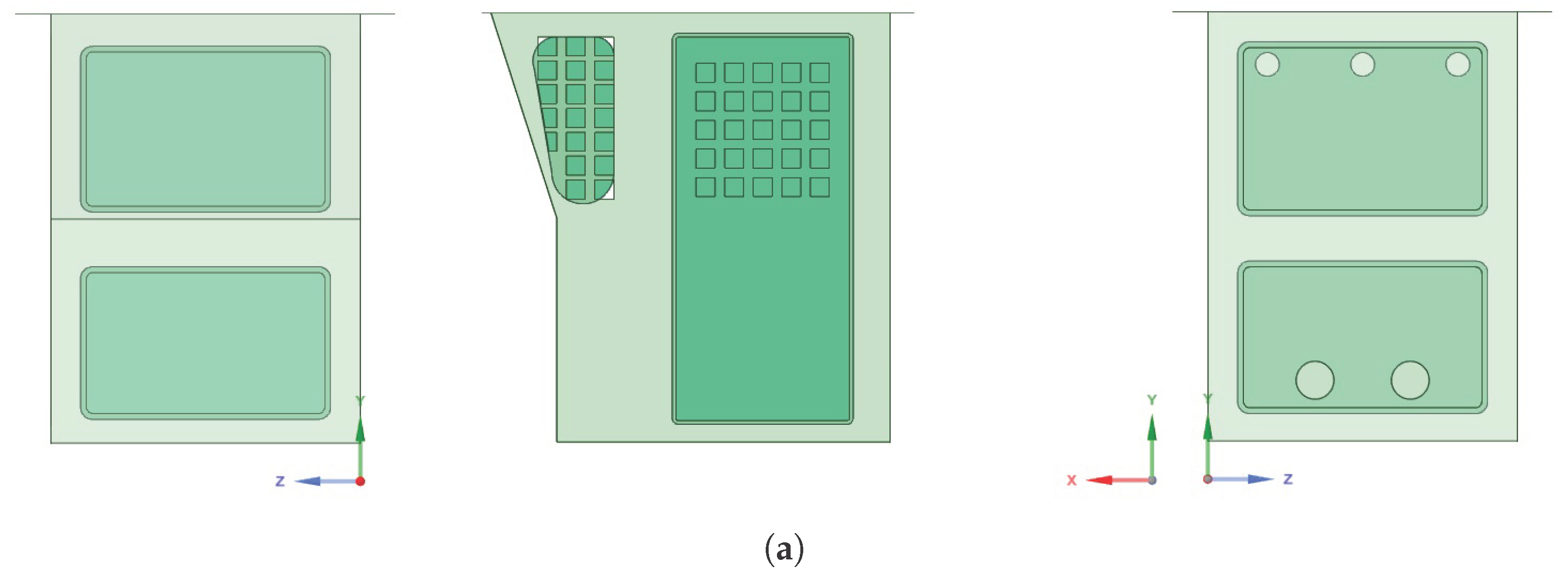
The geometric model of the operator cabin is 1.8 m high, 1.4 m long (by the floor), and 1.3 m wide. The front wall of the cabin at a height of 0.940 m bends at an angle of approximately 162 , so that its length at the ceiling is approximately 1.676 m. Above the bend, there is a window through which the operator controls the hammer. In the symmetrical side walls, there are also windows secured with a lattice, as well as doors. In turn, there are a total of five openings in the rear wall: in the upper part, at a height of 1.580 m, at a distance of 0.250 m from the side edge and 0.400 m apart (center of the openings) three air intake holes with a diameter of 0.100 m each, while in the lower part, at a height of 0.255 m, at a distance of 0.400 m from the center of symmetry of the wall, two outlet holes with a diameter of 0.159 m. Inside the cabin, there is the necessary equipment in the form of a cabin frame made of steel profiles with dimensions of 0.120 × 0.120 m, diffusers that direct air through the inlet openings (preventing the inflow of cooled air directly to the operator), a control panel with dimensions of 0.860 × 0.305 × 0.175 m, as well as the necessary wiring and lighting. In the central part of the cabin, there is the operator’s seat, on which the human model is placed. There is also a fire extinguisher in the lower corner of the cab, behind the operator’s seat. A simplified CAD model created based on the technical sheet of the cabin dimensions is presented in Figure 2a (exterior) and Figure 2b (interior).
Following the guidelines described in [67], a model of the 50th percentile of the male population was made. The model was simplified as much as possible to shorten and maintain the stability of numerical calculations. The dimensions based on which the model used for numerical calculations was created are shown in Table 1.

3.4. Mesh

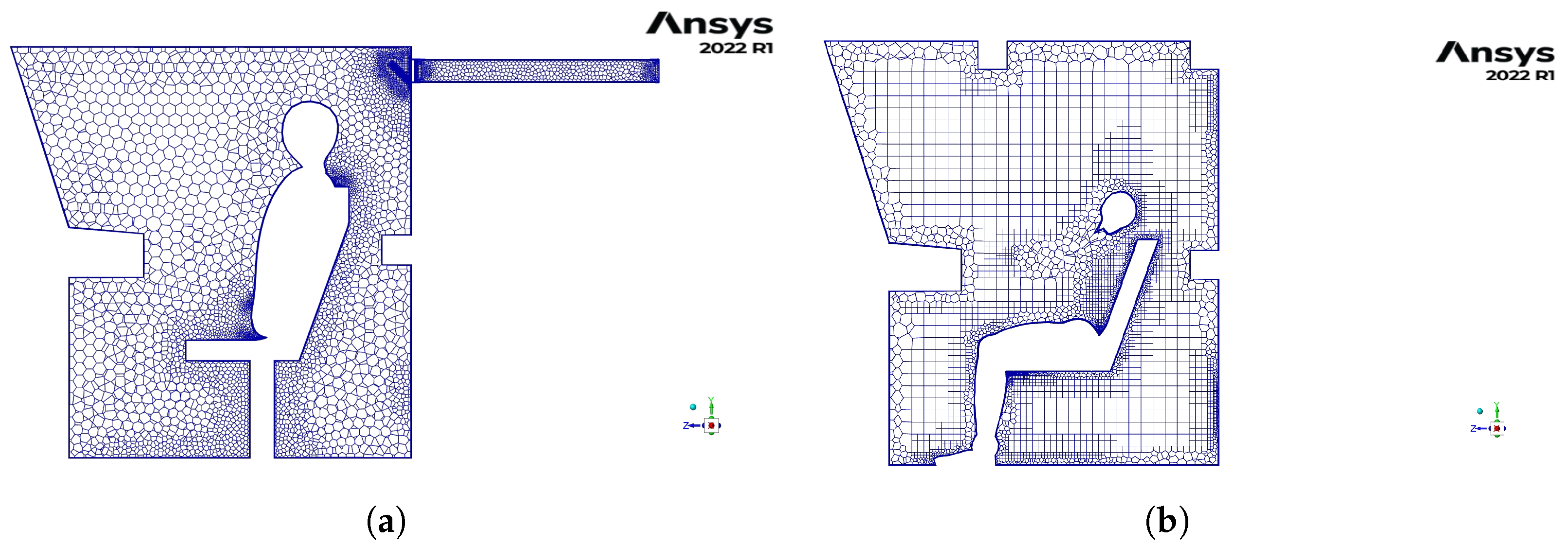
The geometry of the model was simplified to improve the stability of the numerical calculations. For this purpose, the control panel was simplified and unnecessary equipment elements that do not much affect air flow in the operator cabin were removed. Due to the fact that the model is symmetrical in relation to the vertical plane passing through the center of the operator’s cabin, only half of the model was meshed, to shorten the calculation time. A discrete model was made with a poly-hexcore mesh. This type of mesh provides a reduced calculation time with adequate precision [68]. The mesh consists of 2.1 million elements, of which 200 thousand and 1.9 million are hexa- and poly-elements, respectively (Figure 3). A skewness value of 0.80 was achieved and orthogonal quality—0.18.

3.5. Boundary Conditions Applied and Their Determination

Measurement of the airflow velocity and temperature in the air-conditioning vents (inlet air supply holes) was difficult, due to the presence of air-directing diffusers. For this reason, measurements were made using a special nozzle with a narrowed outlet (Ø10 cm) relative to the inlet (Ø30 cm) (Figure 4).
Airflow measurements were conducted with a TSI Airflow Instruments LCA301 anemometer. Following the calibration certificate, the device was verified by the TSI manufacturer, certified to ISO 9001:2015 and accredited to 17025:2017. The measurement range of this device is 0.25–30 m/s in terms of velocity and 0.01–3000 m 3 /s in terms of volumetric, the accuracy of the measurements is +/−1% reading (+/−0.02 m/s) in terms of velocity. The test results showed that the airflow rates at the discharge ports were 2.30 × t 10 2 , 2.50 × 10 2 , and 2.40 × 10 2  m 3 /s, while the vents area was 7.85 × 10 3  m 2 . Thus, the air velocity at the vent was calculated as 2.93, 3.18, and 3.13 m/s, and the average values of 3.06 m/s and 3.00 m/s were applied as the boundary condition.
The ambient air temperature in the excavation was defined using an Assman psychrometer. The dry thermometer reads were 35.0  C in the first measurement, 35.2  C in the second measurement, and 34.8  C in the third measurement, in 5 min periods; thus, the value of 35.0  C was adopted as a radiative temperature boundary condition for all external boundary surfaces of the cabin. Furthermore, the calculations took into account the generation of heat from the human body, and the temperature of 36.6  C was applied as the radiative temperature on its surfaces. The radiative heat transfer model used assumed an internal emissivity value of 1 at the boundaries. The applied boundary conditions are shown in Table 2.

4. Results

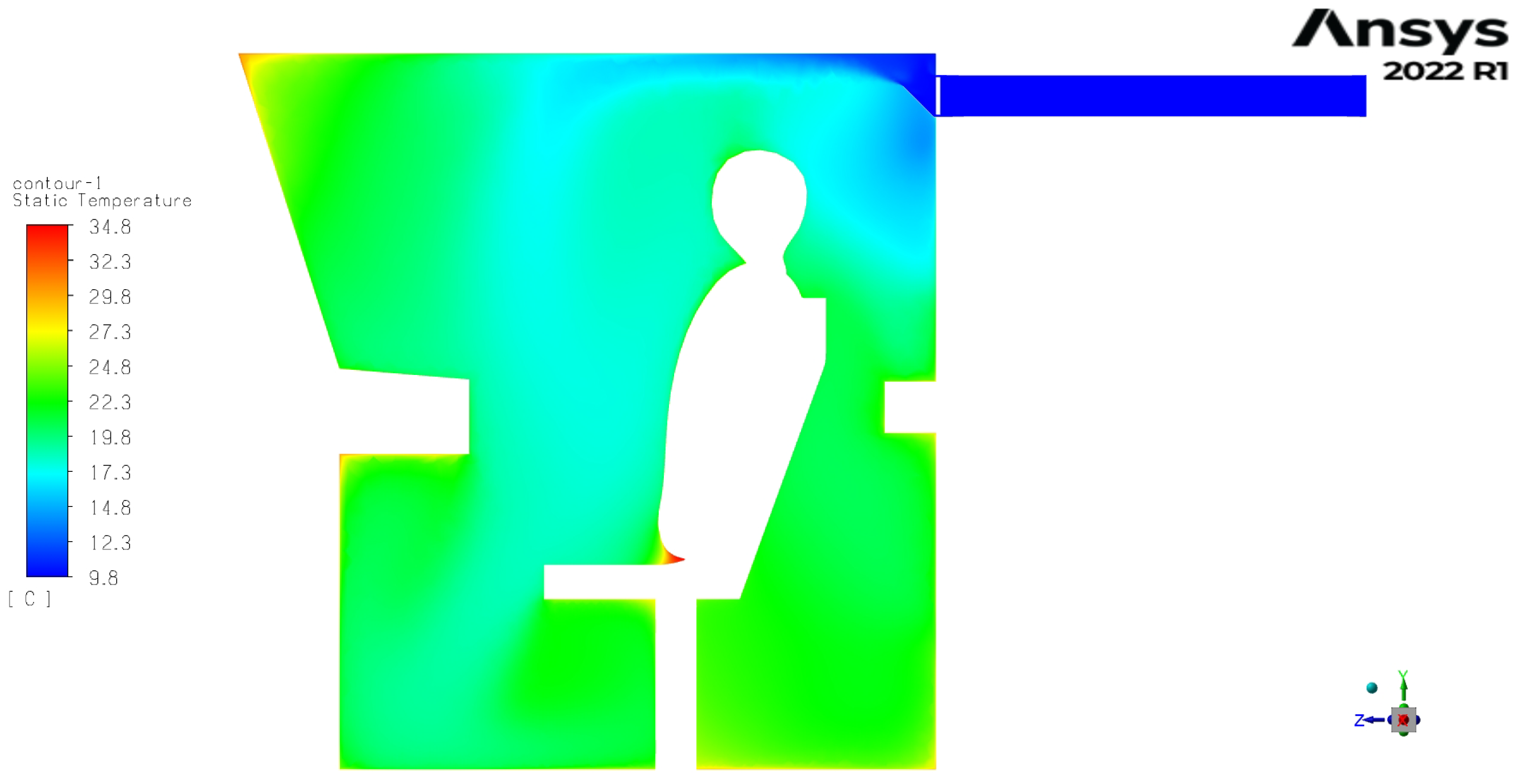
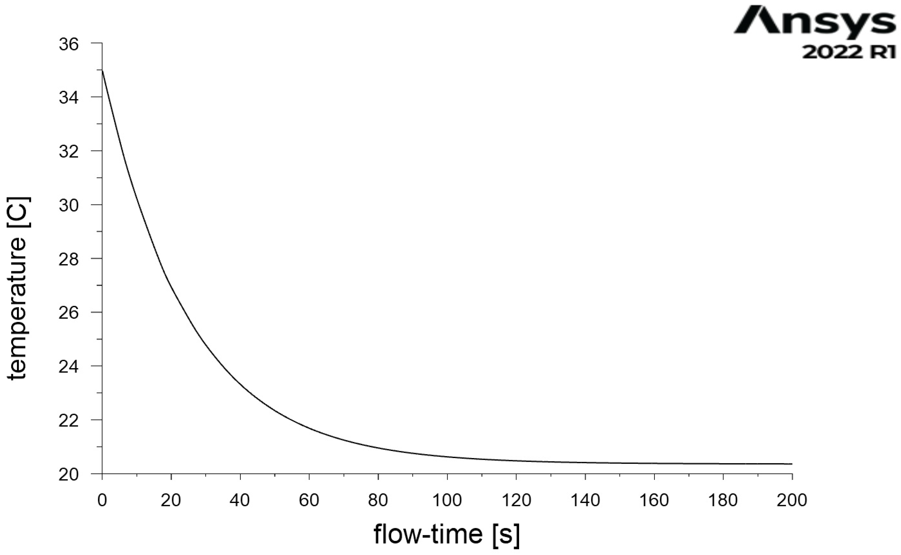
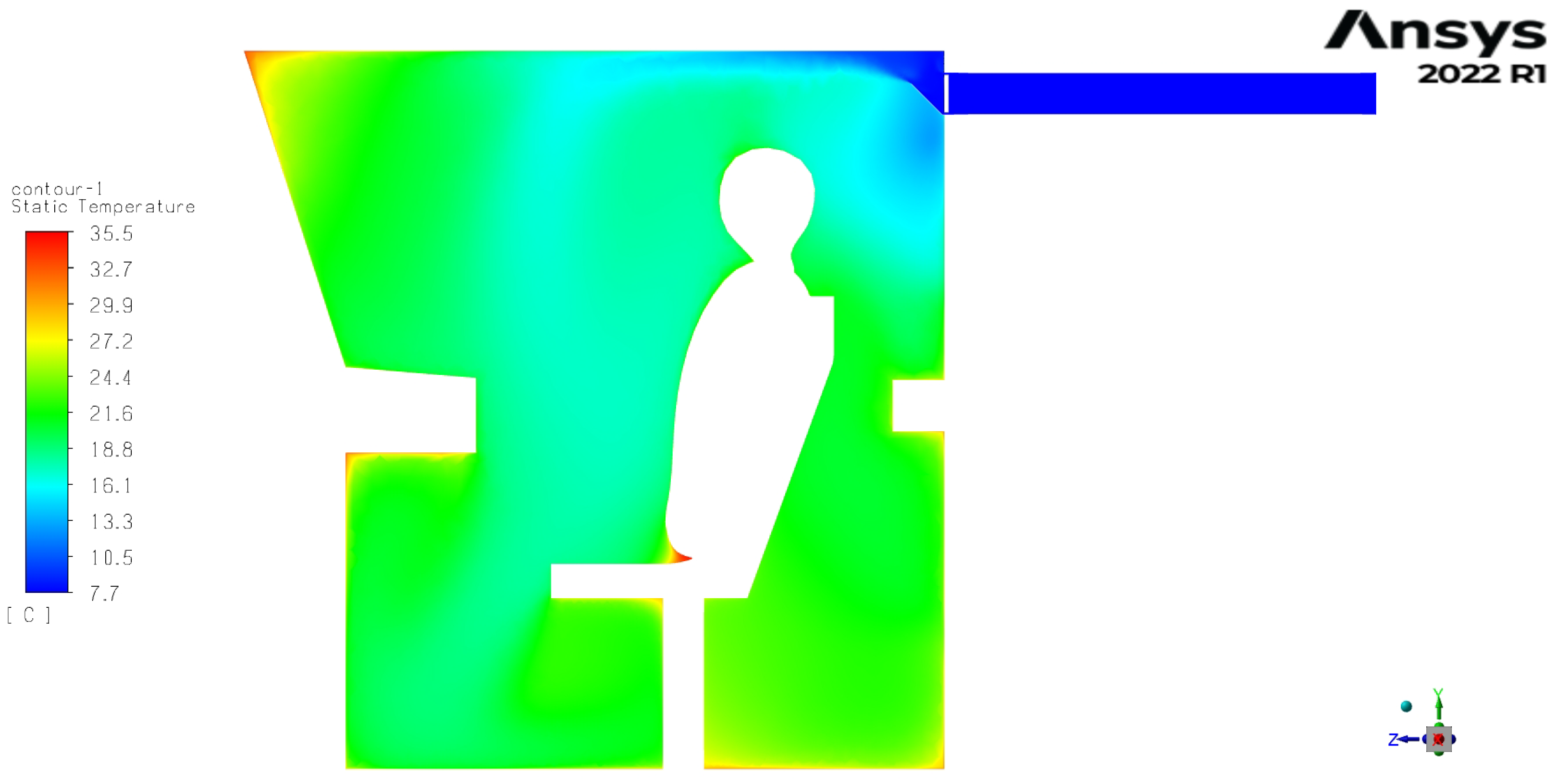
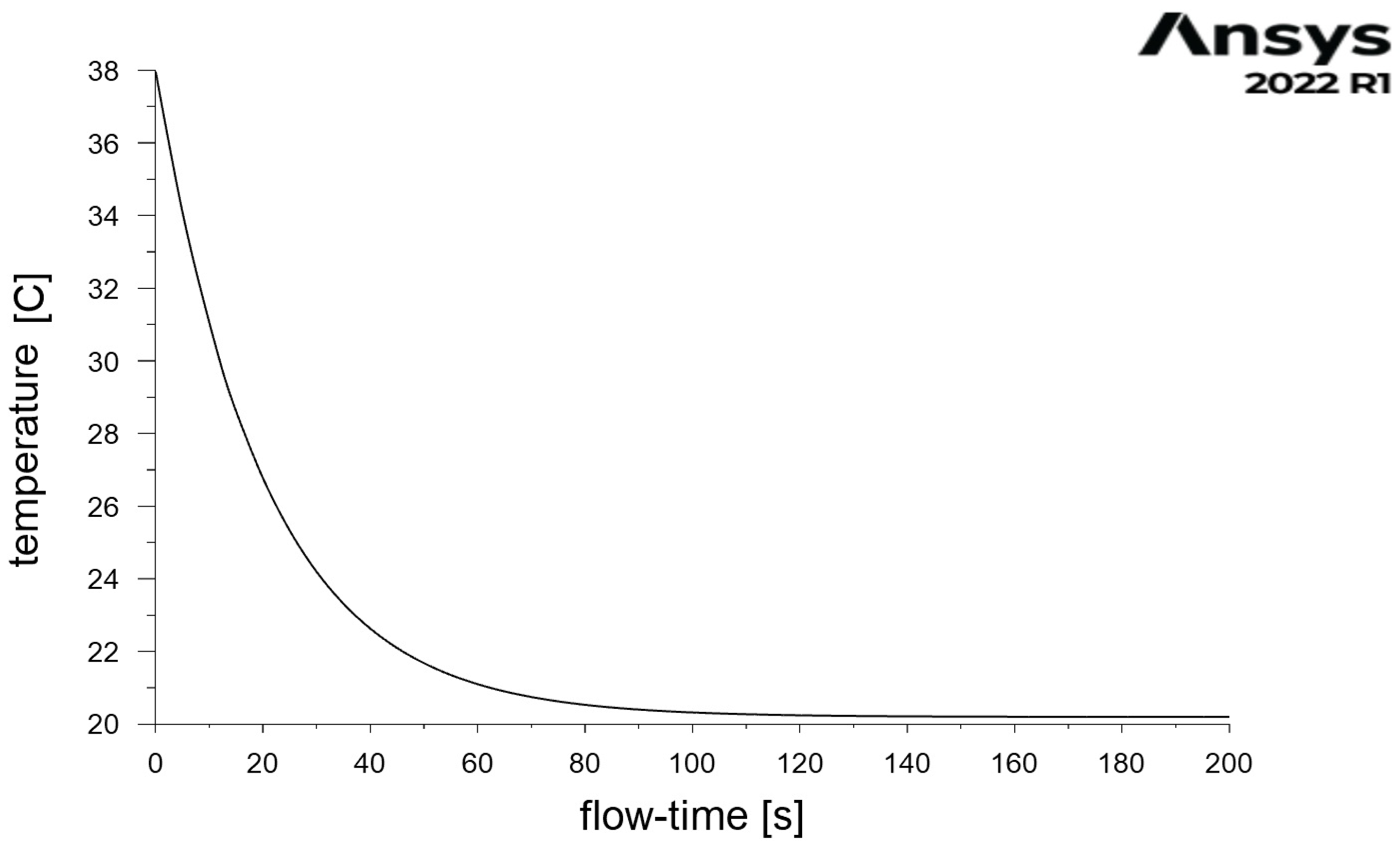
Figure 5 shows the inner airflow streamlines following the velocity variable, while Figure 6a,b show the velocity magnitude field and vectors in the cross section. Figure 7 shows the temperature field in the same cross-section. In turn, Figure 8 shows the results of cabin cooling as the decrease in temperature as a function of time.
Following the trajectory of the conditioned air flowing out of the intake ports, based on airflow streamlines and air velocity magnitude vectors, we can see that there is a secondary vortex around the operator’s head and chest. Another smaller vortex can be seen above and below the control panel, as well as behind the seat. Following the results presented above, the average air velocity in the operator cabin was 0.35 m/s, while the average air temperature was 20.40  C. Considering the air velocity, it can be seen that its distribution is constant in the entire cabin, except for the area near the inlets and air diffusers. On the other hand, the air temperature distribution changes in the cross-section. Cooler temperatures of about 10  C are observed around the diffusers and air-conditioned intakes of the cabin, as expected. In the immediate vicinity of the face and chest, the temperature is slightly warmer, about 18.3  C, than in the greater part of the cabin toward the front window and the control panel (about 17.6  C). This is a direct result of the path of the airflow that comes out of the inlets and circulates in the cabin when an obstacle, in the form of the seat and the operator, appears. In addition, a lower air temperature is noted in the further trajectory of the air-conditioned stream from the inlets under the operator’s panel near his feet, where in the floor area the air stream is refracted and directed toward the outlets. In the remaining parts of the cabin, that is, under and behind the seat and above the control panel, the temperature was relatively constant and reached 21.9  C. The results obtained were consistent with three verification measurements carried out after 15 min of starting the air conditioning and closing the door by the operator at three points in the cabin: above the control panel at the level of the inlets (average 22.7  C), in front of the operator at head/chest height (average 19.5  C), and below the control panel at leg height (average 17.4  C).
Since the 1970s, the methodology for assessing thermal comfort based on the thermal comfort equation created by Fanger has been used globally [69]. In 1970, Fanger [70] defined PMV as an index to predict or represent the mean vote on a standard scale for thermal sensation for a large group of people for any given combination of thermal environmental variables, activities, and clothing levels. It allows predicting the optimum temperature that should be provided for a group in closed spaces. Based on PMV, the predicted percentage of dissatisfaction (PPD) can also be determined. The predicted mean vote (PMV) model has become the internationally accepted model for describing predicted mean thermal perceptions. Furthermore, based on this methodology, the International Organization for Standardization created a standard for the analytical determination of thermal comfort using the calculation of the PMV and PPD indices [71].
For a given parameters, the PMV value can be obtained in two ways. One way relies on calculating the value using the equation developed by Fanger and presented in [70]. However, following the guidelines that can be found there, the mathematical form of PMV is quite complicated and impractical; thus, its author suggests using a more practical method; that is, utilization of prepared tables. The authors used the suggested method to determine the PMV value, focusing primarily on the determination of the parameters needed.
Due to the climatic conditions that prevail in mines, employees are usually equipped with light clothing selected according to personal preferences: a flannel shirt or thermoactive shirt, trousers or thermoactive shorts, work shoes or rubber boots, underwear, and socks. Based on the values defined in [71], it was determined that the thermal insulation of the combination of workwear used by operators is 1 clo (0.115 m 2 K/W), which corresponds to the average value for the set of underwear, overalls, socks, shoes, and for the set of underwear, shirt, overalls, socks, and shoes from the workwear group. Similarly, taking into account the metabolic rate, this value was determined to be 1.2 met (70 W/m 2 ), which corresponds to activity in a sitting position. Based on the results of this calculation, for further estimations, it was assumed that the average airflow velocity inside the cabin was 0.35 m/s, and the air temperature was 20  C.
Considering the above, it was established that the value of the PMV index for the conditions defined in this way ranged from −0.67 to −0.76. This means that the operator’s thermal sensation would range from neutral to slightly cool. The graph in Figure 8 suggests that the conditions referred to above would prevail inside the cab after about 180 s, assuming that the operator enters the cab and closes the door and that the air-conditioning system immediately starts working at full capacity.
Due to the planned development of the mine, the depth of exploitation will increase, and higher ambient air temperatures should be expected in the operator’s workplace. By changing the boundary condition of the external boundary surface radiative temperature to 38  C (which is the predicted dry bulb temperature of the mine air at the planned depths of exploitation of the mining areas currently being prepared) and the air-conditioned air temperature at the inlets, an attempt was made to obtain conditions similar to those that in the previous case gave the same result for the PMV index. This goal was achieved for the air temperature boundary condition at the inlets of 8  C (Figure 9). These conditions, as in the first case and with the same assumptions, would be obtained by the operator after about 180 s (Figure 10). The temperature distribution obtained in the cabin in this case is very similar to the conditions simulated on the basis of the measurement data in the previous case. As the air velocity parameters did not change, the average air velocity remained at 0.35 m/s, while the average air temperature changed slightly to 20.35  C. In the vicinity of the face and chest, the temperature decreased to 17.9  C, while it increased to 17  C in the further part of the cabin toward the front window and the controls. In the remaining parts of the cabin, the temperature remained constant, but increased to 22.2  C. For these thermal conditions, the PMV index remained at the same level, and thus so did the operator’s thermal sensation.
In the case of increased heat flux from the rock mass and intensified extraction, resulting in an increase in the average air temperature at the unit discharge point, it may turn out that the cooling power of the device will not allow for such a significant reduction in the temperature of the conditioned air at the inlets to the cabin. In such a case, an increase in the air temperature inside the cabin and a reduced thermal comfort of the operator should be expected. With limited possibilities for reducing the air temperature at the inlet, in order to maintain satisfactory thermal conditions of work at the station, its speed should be changed. In case 3, the climatic conditions within the cabin were simulated by changing the boundary conditions in the form of increasing the radiative temperature of the external boundary surface to 38  C and the air-conditioned air velocity at the inlets to 4 m/s, while maintaining the temperature at the same level as in case 1 (10  C). The temperature distribution in the cabin in this case is shown in Figure 11. The operator would obtain these conditions in a shorter period of about 150 s (Figure 12).
Furthermore, in this case the temperature distribution obtained in the cabin was similar to that simulated in Case 1 for the conditions that currently prevail in the mine. The average air velocity increased to 0.47 m/s, while the average air temperature decreased to 20.20  C. In the vicinity of the face and chest, the temperature decreased to 17.9  C, while in further part of the cabin toward the front window and the control panel it increased to 17.3  C. In the remaining parts of the cabin, the temperature remained constant and reached 21.5  C. The ultimate goal of maintaining thermal comfort at a similar level, as assessed by the PMV index, was achieved.

5. Conclusions

In this study, in situ measurements of environmental parameters were performed to determine the boundary conditions, based on which CFD simulations were carried out to analyze the thermal conditions in the operator’s workplace for a stationary rock breaker in an underground mine. Based on the simulation results, a thermal comfort assessment was performed using the PMV methodology.
However, taking into account a future planned expansion of exploitation, which would result in an increase in the depth of the works carried out and the intensification of the excavation, two additional cases were also analyzed. Assuming an increase in the average air temperature in the mine, an attempt was made to determine the temperature and velocity of the air-conditioned air flow at the outlet of the air-conditioning device required to maintain the climatic conditions at the same level of PMV.
The PMV value obtained suggests that the thermal sensation in the operator cabin for the microclimate conditions considered in case 1 (currently prevalent in the mine) would range from neutral (PMV = 0) to slightly cool (PMV = −1). On this basis, it can be concluded that the actions taken to reduce the negative impact of microclimatic conditions on the human body in the workplace of the stationary rock breaker operator had the intended effect. Thus, this PMV value was treated as a reference for further investigation of the inlet air parameters that should be ensured to maintain the thermal comfort of the operator.
The results of the CFD simulation showed that similar climatic conditions could be obtained within the operator’s cabin, with a projected increase in the average air temperature to 38  C. In the first of the cases considered, this effect was obtained by lowering the temperature of the air conditioning to 8  C. However, taking into account the limitations in the cooling power of the devices, with a higher temperature in the second case, this effect was achieved by maintaining the current temperature value of 10  C and by increasing the air flow velocity at the inlet to the cabins to 4 m/s.
Presentation of the simulation results in the form of the temperature distribution inside the cabin in the section passing through its center could be used to determine the location of the air temperature measurement points used in the mine to determine the operator’s comfort using PMV, or another indicator determining the level of thermal comfort. Although the velocity distribution was constant in most of the cabin, except for the area near the inlets and air diffusers, the temperature distribution implied that several measurement points should be taken into account to obtain a reliable average cabin temperature. The extreme values found around the inlets and diffusers should not be considered.
Based on the analysis of the results, it was found that, with regard to the PMV index and URB operator cabin, it was reasonable to take measurements at six points. From the point of view of operator comfort, the temperature should be measured in the immediate vicinity of the face/chest. The second point should be located at the same height, in the path of the airflow that comes out of the inlets; and the third, also at the same height, should be located in the vicinity of the front glass. The fourth measurement point should be placed in the path of airflow directed from the inlets to the lower part of the cabin, at the level of the tibias. The last two points should be placed behind the seat, again at the height of the tibia and at the height of the center of the back. Similar temperature values were obtained in the area of the front window and seat (directly below and behind). Due to the difficulties in taking measurements around the seat, they were omitted; however, they should be included in the calculations, taking the value registered at the front window.
The created model of the operator’s cabin allows the prospect of further analyses and simulations aimed at ensuring and maintaining optimal working conditions; especially taking into account other hazards, i.e., the adverse impact of harmful substances contained in mine air in gaseous or solid form, in particular harmful and dangerous gases, dust, and DPM. Future work by the authors will focus on determining the operating parameters of devices and the measurement characteristics needed to counteract these threats, to maintain comfort and comply with regulations in the workplace.

Author Contributions

Conceptualization, A.W., A.B., M.Z. and A.J.; methodology, A.W. and A.M.; validation, M.Z.; formal analysis, A.W.; investigation, A.W. and A.B.; resources, S.G.; data curation, A.M.; writing—original draft preparation, A.W.; writing—review and editing, A.W., A.B., M.Z. and S.G.; visualization, A.M.; supervision, M.Z., A.J. and S.G. All authors have read and agreed to the published version of the manuscript.

Funding

This activity received funding from the European Institute of Innovation and Technology (EIT), a body of the European Union, under the Horizon 2020, the EU Framework Programme for Research and Innovation. This work was supported by EIT RawMaterials GmbH under Framework Partnership Agreement No. 21016 (ECHO: Electrical Computerised Hammering Operator). The project is co-financed by the Polish Ministry of Education and Science within the framework of the program titled International Co-Financed Projects.

Data Availability Statement

Data available on request.

Acknowledgments

The authors would like to thank the company KGHM Polska Miedź S.A. and the authorities and employees of O/ZG Polkowice-Sieroszowice for enabling the performance of underground measurements, and their support and assistance in the implementation of this work.

Conflicts of Interest

The authors declare no conflict of interest.

References

  1. KGHM Polska Miedź, S.A. Deposit Mining Technology. Available online: https://kghm.com/en/our-business/processes/ore-mining/ (accessed on 11 January 2023).
  2. Krot, P.; Śliwiński, P.; Zimroz, R.; Gomolla, N. The identification of operational cycles in the monitoring systems of underground vehicles. Measurement 2020, 151, 107111. [Google Scholar] [CrossRef]
  3. Bortnowski, P.; Gondek, H.; Król, R.; Marasova, D.; Ozdoba, M. Detection of Blockages of the Belt Conveyor Transfer Point Using an RGB Camera and CNN Autoencoder. Energies 2023, 16, 1666. [Google Scholar] [CrossRef]
  4. Zimroz, R.; Król, R. Failure analysis of belt conveyor systems for condition monitoring purposes. Min. Sci. 2009, 128, 255. [Google Scholar]
  5. Blazej, R.; Jurdziak, L.; Zimroz, R. Novel approaches for processing of multi-channels NDT signals for damage detection in conveyor belts with steel cords. In Key Engineering Materials; Trans Tech Publications Ltd.: Wollerau, Switzerland, 2013; Volume 569, pp. 978–985. [Google Scholar]
  6. Trybała, P.; Blachowski, J.; Błażej, R.; Zimroz, R. Damage detection based on 3d point cloud data processing from laser scanning of conveyor belt surface. Remote Sens. 2020, 13, 55. [Google Scholar] [CrossRef]
  7. Wróblewski, A.; Krot, P.; Zimroz, R.; Mayer, T.; Peltola, J. Review of Linear Electric Motor Hammers—An Energy-Saving and Eco-Friendly Solution in Industry. Energies 2023, 16, 959. [Google Scholar] [CrossRef]
  8. Stefaniak, P.; Wodecki, J.; Jakubiak, J.; Zimroz, R. Development of test rig for robotization of mining technological processes—Oversized rock breaking process case. IOP Conf. Ser. Earth Environ. Sci. 2017, 95, 042028. [Google Scholar]
  9. KGHM ZANAM. Stationary Rock Breaker Type URB/Klim. Available online: https://www.kghmzanam.com/wp-content/uploads/2020/06/URB_Klim_PL.pdf (accessed on 5 December 2022).
  10. Tutak, M.; Brodny, J.; Szurgacz, D.; Sobik, L.; Zhironkin, S. The impact of the ventilation system on the methane release hazard and spontaneous combustion of coal in the area of exploitation—A case study. Energies 2020, 13, 4891. [Google Scholar] [CrossRef]
  11. Szurgacz, D. Electrohydraulic control systems for powered roof supports in hazardous conditions of mining tremors. J. Sustain. Min. 2015, 14, 157–163. [Google Scholar] [CrossRef]
  12. Wróblewski, A.; Banasiewicz, A.; Gola, S. Heat Balance Determination Methods for Mining Areas in Underground Mines—A Review. IOP Conf. Ser. Earth Environ. Sci. 2021, 942, 012011. [Google Scholar] [CrossRef]
  13. Hebda-Sobkowicz, J.; Gola, S.; Zimroz, R.; Wyłomańska, A. Identification and statistical analysis of impulse-like patterns of carbon monoxide variation in deep underground mines associated with the blasting procedure. Sensors 2019, 19, 2757. [Google Scholar] [CrossRef]
  14. Hebda-Sobkowicz, J.; Zimroz, R.; Wyłomańska, A.; Gola, S. Identification and statistical analysis of impulse-like patterns of carbon monoxide variation in deep underground mine. AIP Conf. Proc. 2020, 2209, 020005. [Google Scholar]
  15. Hebda-Sobkowicz, J.; Gola, S.; Zimroz, R.; Wyłomańska, A. Pattern of H2S concentration in a deep copper mine and its correlation with ventilation schedule. Measurement 2019, 140, 373–381. [Google Scholar] [CrossRef]
  16. Banasiewicz, A.; Śliwiński, P.; Krot, P.; Wodecki, J.; Zimroz, R. Prediction of NOx Emission Based on Data of LHD On-Board Monitoring System in a Deep Underground Mine. Energies 2023, 16, 2149. [Google Scholar] [CrossRef]
  17. Garcia, J.J.; Gresh, R.E.; Gareis, M.B.; Haney, R.A. Effectiveness of cabs for dust and silica control on mobile mining equipment. In Proceedings of the 8th US Mine Ventilation Symposium, Rolla, MO, USA, 11–17 June 1999. [Google Scholar]
  18. Haney, R.A.; Schultz, M.J.; Rude, R.L.; Tomko, D.M. Controls being used to reduce diesel particulate matter exposures in US underground metal and non-metal mines. In Proceedings of the Eighth International Mine Ventilation Congress, Brisbane, Australia, 6–8 July 2005. [Google Scholar]
  19. Peters, S.; de Klerk, N.; Reid, A.; Fritschi, L.; Musk, A.B.; Vermeulen, R. Estimation of quantitative levels of diesel exhaust exposure and the health impact in the contemporary Australian mining industry. Occup. Environ. Med. 2017, 74, 282–289. [Google Scholar] [CrossRef]
  20. Li, J.; Wu, L.; Chen, H. Analysis of thermal comfort and threshold range of airflow supply parameters for different types of work in humid-heat coal mines. Case Stud. Therm. Eng. 2023, 44, 102826. [Google Scholar] [CrossRef]
  21. You, S.; Sun, J.; Ji, H.; Feng, Q. Analysis of Thermal Environment and Its Influencing Factors in Deep Stope of Metal Mine. Geofluids 2022, 2022, 6408714. [Google Scholar] [CrossRef]
  22. Wei, D.; Du, C.; Lin, Y.; Chang, B.; Wang, Y. Thermal environment assessment of deep mine based on analytic hierarchy process and fuzzy comprehensive evaluation. Case Stud. Therm. Eng. 2020, 19, 100618. [Google Scholar] [CrossRef]
  23. Wang, K.; Li, Q.; Wang, J.; Yang, S. Thermodynamic characteristics of deep space: Hot hazard control case study in 1010-m-deep mine. Case Stud. Therm. Eng. 2021, 28, 101656. [Google Scholar] [CrossRef]
  24. Roy, S.; Mishra, D.P.; Bhattacharjee, R.M.; Agrawal, H. Genetic programming for prediction of heat stress hazard in underground coal mine environment. Nat. Hazards 2022, 114, 2527–2543. [Google Scholar] [CrossRef]
  25. Bornman, W.; Dirker, J.; Arndt, D.C.; Meyer, J.P. Integrated energy simulation of a deep level mine cooling system through a combination of forward and first-principle models applied to system-side parameters. Appl. Therm. Eng. 2017, 123, 1166–1180. [Google Scholar] [CrossRef]
  26. Slazak, N.; Obracaj, D.; Borowski, M. Methods for controlling temperature hazard in Polish coal mines. Arch. Min. Sci. 2008, 53, 497–510. [Google Scholar]
  27. Soroko, K.; Zgrzebski, P.; Stach, R.; Gola, S. Improving underground mine climate conditions using ventilation dams to seal abandoned areas in Polish copper mines. CIM J. 2020, 11, 188–197. [Google Scholar] [CrossRef]
  28. Xiao, Y.; Deng, H.; Xie, Z.; He, W. Application of Nanoporous Super Thermal Insulation Material in the Prevention and Control of Thermal Hazards in Deep Mining of Metal Mines. J. Nanomater. 2022, 2022, 2390616. [Google Scholar] [CrossRef]
  29. Szlązak, N.; Obracaj, D.; Swolkień, J. Thermal Insulation of Excavations and Its Effect on Climate Conditions. Energies 2021, 14, 4170. [Google Scholar] [CrossRef]
  30. Zawiślak, M. Method of Fluid-Flow Machinery and Systems Design and Modernisation by Computational Fluid Dynamics Application; Publishing House of the Poznan University of Technology: Poznan, Poland, 2017. (In Polish) [Google Scholar]
  31. Xu, G.; Luxbacher, K.D.; Ragab, S.; Xu, J.; Ding, X. Computational fluid dynamics applied to mining engineering: A review. Int. J. Min. Reclam. Environ. 2017, 31, 251–275. [Google Scholar] [CrossRef]
  32. Ren, T.; Balusu, R. The use of CFD modelling as a tool for solving mining health andsafety problems. In Proceedings of the 10th Underground Coal Operators’ Conference, Wollongong, Australia, 11–12 February 2010. [Google Scholar]
  33. Yi, H.; Kim, M.; Lee, D.; Park, J. Applications of Computational Fluid Dynamics for Mine Ventilation in Mineral Development. Energies 2022, 15, 8405. [Google Scholar] [CrossRef]
  34. Brodny, J.; Tutak, M. Applying computational fluid dynamics in research on ventilation safety during underground hard coal mining: A systematic literature review. Process Saf. Environ. Prot. 2021, 151, 373–400. [Google Scholar] [CrossRef]
  35. Peng, S.; Huang, Z.; Dong, D. Numerical Simulation Study On Fire Hazard Of A Coal Mine Transport Roadway. Min. Sci. 2022, 29, 33–52. [Google Scholar]
  36. Nezarat, H.R.; Jalali, S.M.E.; Khosrotash, M.; Nazari, M. Reduction of Dead Zones by Improving the Ventilation System Inside the TBM; Technical Report; EasyChair: Manchester, UK, 2019. [Google Scholar]
  37. Liu, Q.; Nie, W.; Hua, Y.; Jia, L.; Li, C.; Ma, H.; Wei, C.; Liu, C.; Zhou, W.; Peng, H. A study on the dust control effect of the dust extraction system in TBM construction tunnels based on CFD computer simulation technology. Adv. Powder Technol. 2019, 30, 2059–2075. [Google Scholar] [CrossRef]
  38. Liu, C.; Bao, Q.; Nie, W. The influence of ventilation parameters on dust pollution in a tunnel’s environment using the CFD method. J. Wind Eng. Ind. Aerodyn. 2022, 230, 105173. [Google Scholar] [CrossRef]
  39. Xu, G.; Chang, P.; Mullins, B.; Zhou, F.; Hu, S. Numerical study of diesel particulate matter distribution in an underground mine isolated zone. Powder Technol. 2018, 339, 947–957. [Google Scholar] [CrossRef]
  40. Chang, P. Comparison of Diesel Particulate Matter Simulation Models and Ventilation Optimisation by Using Computational Fluid Dynamics. Ph.D. Thesis, Curtin University, Bentley, Australia, 2019. [Google Scholar]
  41. Chang, P.; Xu, G.; Zhou, F.; Mullins, B.; Abishek, S.; Chalmers, D. Minimizing DPM pollution in an underground mine by optimizing auxiliary ventilation systems using CFD. Tunn. Undergr. Space Technol. 2019, 87, 112–121. [Google Scholar] [CrossRef]
  42. Wróblewski, A.; Wodecki, J.; Trybała, P.; Zimroz, R. A Method for Large Underground Structures Geometry Evaluation Based on Multivariate Parameterization and Multidimensional Analysis of Point Cloud Data. Energies 2022, 15, 6302. [Google Scholar] [CrossRef]
  43. Janus, J. Air Flow Modelling on the Geometry Reflecting the Actual Shape of the Longwall Area and Goafs. Arch. Min. Sci. 2021, 66, 495–509. [Google Scholar]
  44. Janus, J.; Krawczyk, J. Measurement and Simulation of Flow in a Section of a Mine Gallery. Energies 2021, 14, 4894. [Google Scholar] [CrossRef]
  45. Aboosaidi, F.; Warfield, M.J.; Choudhury, D. Computational fluid dynamics applications in airplane cabin ventilation system design. SAE Trans. 1991, 100, 2082–2091. [Google Scholar]
  46. Zhang, T.; Chen, Q.Y. Novel air distribution systems for commercial aircraft cabins. Build. Environ. 2007, 42, 1675–1684. [Google Scholar] [CrossRef]
  47. Yan, W.; Zhang, Y.; Sun, Y.; Li, D. Experimental and CFD study of unsteady airborne pollutant transport within an aircraft cabin mock-up. Build. Environ. 2009, 44, 34–43. [Google Scholar] [CrossRef]
  48. Li, M.; Yan, Y.; Zhao, B.; Tu, J.; Liu, J.; Li, F.; Wang, C. Assessment of turbulence models and air supply opening models for CFD modelling of airflow and gaseous contaminant distributions in aircraft cabins. Indoor Built Environ. 2018, 27, 606–621. [Google Scholar] [CrossRef]
  49. Liu, W.; Mazumdar, S.; Zhang, Z.; Poussou, S.B.; Liu, J.; Lin, C.H.; Chen, Q. State-of-the-art methods for studying air distributions in commercial airliner cabins. Build. Environ. 2012, 47, 5–12. [Google Scholar] [CrossRef]
  50. Zawiślak, M. Impact of vehicle interior geometry on chosen volatile carcinogens concentration distribution in vehicle cabin. Proc. ECOpole 2013, 7, 177–184. [Google Scholar]
  51. Rodak, M.; Skrętowicz, M.; Janicka, A.; Zawiślak, M. Numerical analysis of volatile organic compounds concentration in a C segment vehicle interior. Combust. Engines 2015, 54, 1042–1045. [Google Scholar] [CrossRef]
  52. Dudycz, A.; Górniak, A.; Janicka, A.; Rodak, M.; Skrętowicz, M.; Trzmiel, K.; Włostowski, R.; Woźniak, J.; Zawiślak, M. Numerical analysis of volatile organic compounds concentration in AC segmnet vehicle interior–diesel engine exhoust pollution. J. Pol. CIMEEAC 2015, 10, 41–48. [Google Scholar]
  53. Zawiślak, M. Application of computational fluid dynamics in the assessment of the spread of toxic compounds emitted by a diesel engine inside a vehicle. J. Pol. CIMAC 2014, 9, 197–205. [Google Scholar]
  54. Hadi, J.M.; Alturaihi, M.H.; Jasim, N.Y.; Habeeb, L.J. Numerical study of airflow and temperature variations inside car at different solar intensity angles. Mater. Today Proc. 2022, 60, 1689–1695. [Google Scholar] [CrossRef]
  55. Mao, Y.; Wang, J.; Li, J. Experimental and numerical study of air flow and temperature variations in an electric vehicle cabin during cooling and heating. Appl. Therm. Eng. 2018, 137, 356–367. [Google Scholar] [CrossRef]
  56. Basciotti, D.; Dvorak, D.; Gellai, I. A novel methodology for evaluating the impact of energy efficiency measures on the cabin thermal comfort of electric vehicles. Energies 2020, 13, 3872. [Google Scholar] [CrossRef]
  57. Singh, S.; Abbassi, H. 1D/3D transient HVAC thermal modeling of an off-highway machinery cabin using CFD-ANN hybrid method. Appl. Therm. Eng. 2018, 135, 406–417. [Google Scholar] [CrossRef]
  58. Oh, J.; Choi, K.; Son, G.h.; Park, Y.J.; Kang, Y.S.; Kim, Y.J. Flow analysis inside tractor cabin for determining air conditioner vent location. Comput. Electron. Agric. 2020, 169, 105199. [Google Scholar] [CrossRef]
  59. Akdemir, S.; Öztürk, S.; Ülger, P. CFD modelling of ambient factors in a tractor cabin for summer conditions. J. Tekirdag Agric. Fac. 2016, 13, 46–54. [Google Scholar]
  60. Akdemir, S.; Öztürk, S.; Ülger, P. CFD modelling of air velocity in a tractor cabin for winter conditions. In Proceedings of the VII International Scientific Agriculture Symposium, “Agrosym 2016”, Jahorina, Bosnia and Herzegovina, 6–9 October 2016; University of East Sarajevo, Faculty of Agriculture: Sarajevo, Bosnia and Herzegovina, 2016; pp. 1829–1835. [Google Scholar]
  61. Hwang, J.H.; Lee, J.S.; Kim, Y.H.; Kim, P.Y. Evaluation Method of Thermal Comfort in Excavator Cabin. In Proceedings of the ASME International Mechanical Engineering Congress and Exposition, San Diego, CA, USA, 15–21 November 2013; Volume 56345, p. V08AT09A031. [Google Scholar]
  62. Ghorpade, U.S.; Patil, M.A.; Shelake, A.S.; Ghodake, H.S. CFD Analysis of Manipulator Cabin by Selecting Proper Air Conditioning System. J. Eng. Res. Appl. 2017, 7, 116–120. [Google Scholar] [CrossRef]
  63. Cimbala, J.M.; Cengel, Y.A. Fluid Mechanics: Fundamentals and Applications; McGraw-Hill Higher Education: New York, NY, USA, 2006. [Google Scholar]
  64. ANSYS, Inc. ANSYS FLUENT Theory Guide; ANSYS, Inc.: Canonsburg, PA, USA, 2013; pp. 90311–90312. [Google Scholar]
  65. Shaheed, R.; Mohammadian, A.; Kheirkhah Gildeh, H. A comparison of standard k–ε and realizable k–ε turbulence models in curved and confluent channels. Environ. Fluid Mech. 2019, 19, 543–568. [Google Scholar] [CrossRef]
  66. KGHM ZANAM. Stationary Rock Breaker Type URB/K. Available online: https://www.kghmzanam.com/wp-content/uploads/2020/06/URB_K_PL.pdf (accessed on 5 December 2022).
  67. Schneider, L.W. Development of Anthropometrically Based Design Specifications for an Advanced Adult Anthropomorphic Dummy Family; Technical Report; Final Report; Regents of the University of Michigan: Ann Arbor, MI, USA, 1983; Volume 1. [Google Scholar]
  68. Zore, K.; Sasanapuri, B.; Parkhi, G.; Varghese, A. Ansys mosaic poly-hexcore mesh for high-lift aircraft configuration. In Proceedings of the 21st AeSI Annual CFD Symposium, Bangalore, India, 8–9 August 2019. [Google Scholar]
  69. Fanger, P.O. Calculation of thermal comfort: Introduction of a basic comfort equation. ASHRAE Trans. Part II 1967, 73, III4.1–III4.20. [Google Scholar]
  70. Fanger, P.O. Thermal Comfort. Analysis and Applications in Environmental Engineering; Danish Technical Press: Copenhagen, Denmark, 1970; 244p. [Google Scholar]
  71. ISO7730; Ergonomics of the Thermal Environment—Analytical Determination and Interpretation of Thermal Comfort Using Calculation of the PMV and PPD Indices and Local Thermal Comfort Criteria. International Organization for Standardization: Geneva, Switzerland, 2006.
Figure 1. Stationary Rock Breaker Type URB/K (1—manipulator; 2—generator; 3—control panel in the operator’s cabin [66]).
Energies 16 03814 g001
Figure 2. Simplified CAD model of the cabin with the human model. (a) Front, side, and rear view of the cabin exterior; (b) side view for the cabin interior.
Energies 16 03814 g002aEnergies 16 03814 g002b
Figure 3. Poly-hexcore mesh elements. (a) Isotropic poly-prisms in the boundary layer; (b) hexahedron elements in the bulk region.
Energies 16 03814 g003
Figure 4. Airflow measurements with the nozzle.
Energies 16 03814 g004
Figure 5. Airflow streamlines colored by the velocity variable.
Energies 16 03814 g005
Figure 6. Air velocity distribution inside the operator’s cabin. (a) Air velocity magnitude field; (b) Air velocity magnitude vectors.
Energies 16 03814 g006
Figure 7. Temperature field inside the cabin.
Energies 16 03814 g007
Figure 8. Decrease in average air temperature over time inside the cabin.  f ( x ) = 0.2711 e 2.323 x + 293.5 e 1.297 × 10 5 x R 2 = 1 , RMSE < 1%.
Energies 16 03814 g008
Figure 9. Temperature field inside the cabin—case 2.
Energies 16 03814 g009
Figure 10. Decrease in average air temperature over time inside the cabin—case 2.  f ( x ) = 0.3226 e 2.33 x + 293.5 e 1.378 × 10 5 x R 2 = 1 , RMSE < 1%.
Energies 16 03814 g010
Figure 11. Temperature field inside the cabin—case 3.
Energies 16 03814 g011
Figure 12. Decrease in average air temperature over time inside the cabin—case 3.  f ( x ) = 18.76 e 0.04994 x + 293.4 e 2.469 × 10 7 x R 2 = 1 , RMSE < 1%.
Energies 16 03814 g012
Table 1. Dimensions for creation of the 50th percentile of the male population model (based on [67]).
DescriptionDimensions (mm)
Total Sitting Height884
Shoulder Pivot Height513
H-Point Height—ref.88.5
H-Point from seat Back—ref.137
Shoulder Pivot from Backline89
Thigh Clearance147
Elbow to Wrist Pivot297
Shoulder to Elbow338
Elbow Rest Height201
Buttock to Knee592
Popliteal Height442
Knee Pivot to Floor493
Buttock Popliteal Length465
Chest Depth221
Foot Length259
Foot Width99
Shoulder Width429
Chest Circumference965.5
Waist Circumference851
Table 2. Boundary Conditions Applied.
NameBoundary Condition
InletsVelocity—3 m/s; Temperature—10  C
OutletsPressure—0 Pa
HumanTemperature—36.6  C, Radiation (internal emissivity—1)
CabinTemperature—35.0  C, Radiation (internal emissivity—1)
Disclaimer/Publisher’s Note: The statements, opinions and data contained in all publications are solely those of the individual author(s) and contributor(s) and not of MDPI and/or the editor(s). MDPI and/or the editor(s) disclaim responsibility for any injury to people or property resulting from any ideas, methods, instructions or products referred to in the content.