Abstract
Electric vehicles (EV) are now considered the present and future of road transportation to reduce the emission of CO2 into the environment and thus progressively reduce global warming and climate change. However, EVs currently have some weaknesses such as the available range of battery-powered EVs and the recharging time of the batteries. To overcome these problems, some electrification projects have been proposed for road transportation such as the dynamic wireless power transfer (DWPT), where an EV charges as it moves along an electrified lane using magneto-resonant coupling between short tracks mounted on the road pavement and the vehicle’s onboard pickup coils. While the results are encouraging from an electrical point of view, there is concern regarding the magnetic field in the environment produced by the DWPT coils, which can produce adverse health effects in humans and electromagnetic interference (EMI) in electronic devices. The latter also includes implantable medical devices (IMDs) and in particular cardiac implantable electronic devices (CIEDs), which may be present among vehicle passengers and pedestrians in areas surrounding the vehicle. The aim of this study is the numerical analysis of the EMI produced by a DWPT system in CIEDs with leads such as pacemakers, implantable cardioverter defibrillators (ICDs), etc. EMI is mainly produced by the incident magnetic field and the induced voltage at the input port of a CIED; therefore, in this work the magnetic field levels produced by a DWPT system operating at 85 kHz are calculated first, then the voltage at the input port of a pacemaker is evaluated as that produced by the magnetic field incident on the loop surface formed by a lead implanted in the venous system. According to ISO 14117 standard, it is assumed that the lead loop is planar, semicircular in shape and with an area equal to 225 cm2. Since the lead can be placed anywhere where a human can be and with any orientation, an innovative and sophisticated roto-translation algorithm is proposed to find the maximum value of the peak-to-peak induced loop voltage in the most critical regions inside the vehicle cabin and beside the vehicle near the DWPT coils. The preliminary results obtained show that there is no EMI risk inside the vehicle for the passengers with CIEDs, while some concern for pedestrians is due to the induced voltage at the input port of a CIED with unipolar leads which can exceed the ISO 14117 limit in the region next to the vehicle.
1. Introduction
Battery-powered electric vehicles (EVs) will play a major role in the future of road transportation. However, the EV battery is expensive, heavy and takes a long time to charge. To reduce the size and cost of the battery, an attracting idea is to charge it as the EV moves along an electrified lane. WPT (Wireless Power Transfer) technology [1,2,3,4], which relies on inductive coupling between a road surface-mounted coil and a vehicle-mounted coil, makes this possible [5,6,7,8,9,10,11,12,13,14,15,16,17,18,19,20,21,22,23,24,25,26]. The technology for vehicles in motion is known as dynamic WPT (DWPT) and is much more challenging than stationary WPT, which operates only when an EVs is parked. With DWPT technology, the range of electric vehicles can be very long and practically infinite because the battery can be recharged while driving. Therefore, a large on-board battery capacity is not needed to extend range, drastically reducing cost and weight of EVs [12,13,14]. In the recent past, several studies were addressed to improve the electrical efficiency of DWPT systems [15,16,17,18,19] or to mitigate the power hole during the vehicle motion between adjacent short-track coils in the ground [20,21,22,23]. Other studies were focused on the reduction of the magnetic field emission [24,25].
Planning infrastructure for an electrified road faces a number of challenges. One crucial factor is the electromagnetic pollution caused by currents flowing through the coils of the DWPT system, which can create a strong time-varying magnetic field in the environment. This field can produce adverse health effects in humans and electromagnetic interference (EMI) in electronic devices, including implantable medical devices (IMDs) and in particular cardiac implantable electronic devices (CIEDs). Potential victims are people in the immediate vicinity of the vehicle during wireless charging, who are mainly pedestrians, bystanders and vehicle passengers. This work is aimed at analyzing the possible interaction in terms of EMI between the magnetic field produced by a DWPT system and CIEDs with leads such as pacemakers, implantable cardioverter defibrillators (ICDs), etc. For people with cardiac dysfunction, the use of CIEDs is steadily expanding and therefore increases the risk of EMI [26,27,28,29,30]. In fact, a CIED may malfunction, become damaged or overheat due to critical EMI [31,32,33]. Therefore, prior to large-scale implementation of DWPT systems, a thorough investigation of the intermediate frequency (IF) electromagnetic fields generated by DWPT systems is required to assess any risks to patients with CIEDs.
The main purpose of current EMC standards such as ISO 14117 [31] is to prevent EMI in the electronic circuits of CIEDs. A magnetic field generated by a DWPT system can induce voltage on the loop created by the conductor such as pacing leads in a pacemaker. Furthermore, the incident magnetic field can directly generate EMI on the CIED. The ISO 14117 standard is primarily designed to protect a CIED from exposure to an electromagnetic field that can induce currents from the lead into the heart causing local fibrillation or heating, inducing voltage in the lead that can damage the CIED and inducing voltage in the lead that can prevent the CIED from correctly monitoring the intrinsic heart signal (ECG) [31].
For the reasons mentioned above, a key factor for the development of the next generation DWPT systems for EVs is the control and mitigation of the magnetic field emitted in the environment which can be responsible for EMI in CIEDs. The solution of this issue is not easy as a reduction in the magnetic field may have a negative impact on the inductive coupling between the coils, reducing electrical performance of the DWPT system. Furthermore, the mitigation of IF electromagnetic fields is still an open issue. However, the characterization of the magnetic field in and around the vehicle and nearby the electrified road is of primary importance.
In this study, a DWPT system having the configuration proposed in the Fabric Project is adopted as magnetic source [34]. The architecture of this DWPT system is based on rectangular-shaped short-track primary (transmitter (Tx) or ground assembly (GA)) coils mounted in the road pavement and powered in AC at 85 kHz. Each EV is equipped with a pick-up (receiver (Rx) or vehicle assembly (VA)) coil connected to a rectifier to charge the internal battery and can draw up to 10 kW. The coupling factor between the coils is not fixed but is variable due to EV movement. The configuration of a GA coil and a VA coil is analyzed by an electromagnetic field solver considering different reciprocal positions of the coils along the axis of the lane and on the lateral axis. The worst cases in terms of magnetic field levels are recorded for different coil misalignments and types of cars in terms of shape and body material. The calculated magnetic field is compared with the standard limits. Furthermore, the voltage induced in a normalized lead loop (with a surface area of 225 cm2 and semicircular shape) is calculated for any position and orientation of the loop in the critical regions where the magnetic field is maximum. These kinds of calculations, based on many thousands of roto-translations of the lead loop, require a very sophisticated algorithm as described in detail in the next sections. Finally, the simulated results in terms of EMI for CIEDs are shown for different EV/DWPT configurations.
2. DWPT System
2.1. DWPT Configuration
In the DWPT system, the electric power has to be transferred when the vehicle is in motion, so not just a single transmitter is adopted but typically there are several transmitting coils mounted on the road pavement and activated in sequence [35]. In recent years, two different transmitting architectures have been developed for DWPT systems: The first, called long-track DWPT, adopts a very long transmission coil (much longer than the length of the vehicle). The second, called short-track DWPT, adopts a large number of small GA coils activated in sequence. A sketch of the operation of the two architectures is shown in Figure 1. The main advantages of the long-track architecture are the possibility of having a very smooth and uniform power transfer during the motion of the vehicle and an easier installation of the system since it is possible to electrify a long track of the road with only a single coil and an electronic unit. On the other hand, the main problems are the high level of the magnetic flux leakage due to the very large difference in dimensions between the GA and VA coils. Flux leakage leads to a reduction in electrical efficiency and also to significant electromagnetic compatibility (EMC) and electromagnetic field (EMF) safety issues as pedestrians can be directly exposed to the magnetic field.
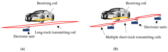
Figure 1.
DWPT coil architecture: Long-track architecture (a) and short-track architecture (b).
For short-track systems, the main benefits are maximizing efficiency and power transfer due to good coupling between coils. Leaked magnetic flux is also reduced and consequently EMF safety and EMC problems are reduced. On the other hand, the short-track architecture is more complicated as more coils and related electronic units are needed to cover the same length of road compared to the long-track solution. The last drawback is the discontinuity of the transferred power due to the passage between one transmitting coil and the next during the EV movement. The maximization of the efficiency and the reduction of the EMF safety problem make the short-track DWPT today the most promising but also the most complex solution. However, there are some important points that need to be considered before adopting this solution. First, the size of the GA coil is a critical parameter, as a shorter GA coil allows high levels of efficiency, but the EV can only be powered for a short distance comparable to the length of the coil. Conversely, a longer GA coil allows for high transmission coverage but with reduced efficiency, due to high magnetic flux leakage. In addition to the size of the individual VA coil, another critical aspect is the separation between adjacent GA coils along the way (x-axis in this study). To operate the system in optimal conditions, the GA coil turns on only when the VA coil is sufficiently aligned with the GA coil itself. Therefore, in the gap between two adjacent GA coils, the VA coil is not energized.
To analyze the magnetic coupling between a GA coil and a VA coil, it is important to consider the movement of the EV, which leads to a continuous change of the coupling factor between the coils. However, from an electrical point of view, the coupling factor variation in a DWPT system can be modeled as a time sequence of static configurations of coils, each characterized by a coil misalignment dependent on the EV position, which is related to the EV speed. In fact, the movement of the vehicle is extremely slow if compared with the time period of the DWPT system, which depends on the working frequency. The time period at the resonant frequency of 85 kHz is equal to 11.7 μs; therefore, in this time a vehicle traveling at 60 km/h only moves 0.2 mm, which is a negligible distance when compared to the size of the coils. Thus, we can analyze the DWPT system as static with a discrete sequence of different coil positions without directly considering EV movement. Furthermore, in short-track systems only one transmitting coil is activated at a time, when the presence of the vehicle is detected and the coupling with the receiver is greater than a pre-set value.
2.2. DWPT Equivalent Circuit
The study of the system considering only one GA coil and one VA coil in different discrete positions allows an analysis of the DWPT system as a traditional stationary WPT considering different misalignment positions. The operating principle is based on the magnetic coupling between a GA coil and a VA coil installed under the vehicle body. The transmitter unit is composed of an electronic unit which transforms the input voltage of the electrical network into a high-frequency AC voltage to power the coil. A compensation network is used on both the GA and VA coils to achieve the resonance condition in order to improve the electrical performance. On the receiving side, the VA coil is connected to the compensation network and to a rectifier, which transforms the high-frequency voltage into direct voltage used to recharge the battery [36,37,38,39,40,41,42,43]. For the analysis of the magnetic coupling and system performances, an equivalent simplified circuit can be adopted, as shown in Figure 2. The GA electronic unit is modeled as a sinusoidal voltage source Vs in series with the resistance RS and the load is modeled with the resistance RL.
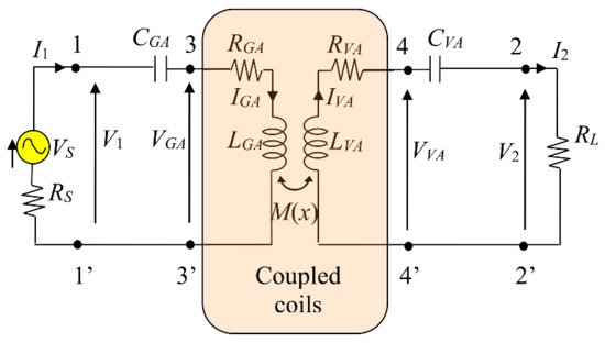
Figure 2.
Equivalent circuit of a WPT system with SS compensation.
The coils are modeled with self resistances, RGA and RVA, and self inductances, LGA and LVA, for the GA and VA, respectively [44,45]. The coupling factor k between the coils is defined as:
where M is the mutual inductance which depends on the variable reciprocal position of the coils due to the EV movement. However, as mentioned above, it assumes a number of static setups with different coil configurations.
Different compensation topologies can be adopted: one of the most common is based on capacitors connected in series on both the GA and VA coils, which is called series-series (SS). A significant advantage of SS compensation is that the capacitor values depend only on the self-inductances of the coil and not on the mutual inductance. This aspect is very important in a DWPT system where there is a continuous variation of the coupling factor k with time. The calculation of the compensation capacitors can be found in [1].
The output power P2 (i.e., the real power transferred to the load RL) and the system efficiency η are the main quantities defining the electrical performance of a WPT system. They can be predicted from equivalent circuit analysis. The efficiency η is defined as:
where P1 is the real power at the input port of the equivalent circuit.
The magnetic field produced by the coil currents is calculated by tridimensional (3D) simulations using numerical software based on the finite element method (FEM) to solve the magneto-quasi-static (MQS) field equations. The self and mutual inductances of the coils (LGA, LVA and M) are then extracted from the magnetic energy Wm stored in the computational domain as described in [46].
The coils are made of litz wire [47]. Since the numerical modeling of this type of wire is exceedingly complex and prone to error, the AC resistances of coils made with litz wires (RGA and RVA) are obtained from technical datasheet. Usually, the AC resistance of an adequate litz wire is not very different from the DC resistance.
It should be noted that as the mutual inductance between the coils is a function of the reciprocal position of the coils on the three rectangular axes, it can thus can be expressed as M(Δx, Δy, Δz), when Δx, is the separation between the centers of the GA and VA coils along the road axis, Δy is the lateral misalignment and Δz is the vertical misalignment which is nearly the ground clearance. In stationary WPT systems, the mutual position of the coils does not change throughout the charging process. In DWPT systems, there is a continuous variation of the mutual position of the coils, mainly on the x-axis which is the direction of vehicle movement. In the following, to reproduce the movement of the vehicle, several discrete values of Δx are taken into account, while the worst-case condition (i.e., maximum coil misalignment) is considered in terms of lateral offset (maximum Δy) and vertical separation (maximum Δz).
As the mutual inductance is variable with mutual positions of the coils, M = M(Δx,Δy,Δz), the efficiency in (2) is given by:
where ω0 = 2πf0 is the angular frequency at resonance.
To predict the magnetic field, it is important to first calculate the coil currents using equivalent circuit analysis, and then those currents can be imposed as sources in the magnetic field simulation. For each configuration of the coils, i.e., for each value of M(Δx,Δy,Δz), a field simulation must be carried out.
3. Mathematical Method
3.1. System Configuration
It is of the utmost importance that the magnetic field produced by automotive WPT systems complies with the ICNIRP reference levels for EMF safety [48,49]. The most critical areas in automotive DWPT systems for humans are inside the vehicle cabin, mainly at the bottom near the coils or outside near the short-range coils, while the area under the vehicle between the coils cannot be considered due to the movement of the electric vehicle; therefore, in this case, the greatest risk is not the electromagnetic field exposure but the much more serious case of a pedestrian being hit by the moving car.
The magnetic field creates risks of EMI in CIEDs, especially in those devices with leads such as pacemakers and ICDs. In the latter devices, the time-varying magnetic field induces a voltage by Faraday’s law of induction on the loop formed by the lead path. At the frequency of 85 kHz, the low frequency approximation can be calculated and the following equations can be used for simulating the considered configuration:
where J is the current density, E is the electric field, H is the magnetic field, A is the magnetic vector potential, Jext is the external current density source, B is the magnetic flux density, V is the electric potential, σ is the conductivity and ε is the electric permittivity.
The induced voltage V in a loop can be calculated by Faraday’s law of induction by:
where ω = 2πf is the angular frequency when f is the frequency; ϕ is the magnetic flux produced by the WPT coils and linked with the lead loop area S within the human body by:
where n is the normal unit vector to the surface S or in terms of magnetic vector potential by:
where Γ is the closed boundary of the loop area S and t is the tangent unit vector to Γ.
In CIEDs with unipolar leads such as pacemakers or ICDs, the cathode is the tip of the lead connected to a chamber of the heart while the anode is the metal casing of the CIED itself. Therefore, for a lead exposed to an incident magnetic field, the lead loop area will collect an incident magnetic flux which will produce an electromotive force V due to Faraday’s law of induction at the input port of a CIED. Then, the first problem is to identify the loop area S that depends on the lead path in the venous system. This area plays a significant role in the calculation of the magnetic flux in (10) and is relatively large only for unipolar leads, while it is small for bipolar leads. Furthermore, S depends on the length of the lead (from the device to the lead tip in the atrial or ventricular heart chamber) implant location (left pectoral or right pectoral), as shown in Figure 3. An implanted lead creates an open loop, so to uniquely identify a closed surface the open loop is closed by a segment line connecting the device with the lead tip [31]. This segment line represents an ideal current return path. Finally, the lead loop is generally not planar. However, to simplify the study due to the high variability of implants and body conformations, the loop area has been standardized where S is planar, with 225 cm2 effective area and with a semicircle shape. Prediction of the maximum induced voltage V on the effective loop area S by (9)–(10) is one of the primary goals of the proposed work.
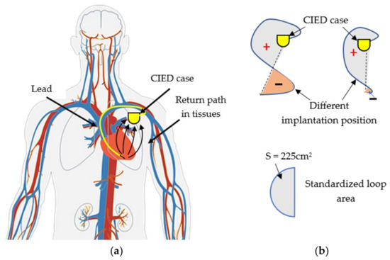
Figure 3.
Sketch of a CIED with a lead and possible current return path (a). Effective lead loop area and standardized loop area S (b).
3.2. Magnetic Flux Calculation
The magnetic field distribution is calculated by solving the equations in (4)–(8) in the field domain configuration of a DWPT system in the presence of the vehicle body. After calculating the magnetic field, it is possible to compare the results obtained with the AC magnetic field limit of ISO 14117 given in terms of the rms magnetic field set at 150 A/m for frequencies up to 100 kHz. It should be noted that 150 A/m corresponds in the air to 188.5 μT, which is higher than the ICNIRP 2010 reference level set at 27 μT at 85 kHz for the protection of the general public from AC magnetic fields [48]. It means compliance with ICNIRP 2010 ensures compliance with ISO 14117 for exposure to AC magnetic fields.
For EMI protection, after evaluating the maximum magnetic field, we also need to calculate the maximum induced voltage V in a lead loop area. Formula (9) is very simple, but calculating the flux ϕ in (10) is not easy at all. First, we adopt a planar semicircle loop of area S = 225 cm2. However, the main difficulty in the calculations is that the semicircle area S can be located anywhere in the computational domain where people can be and oriented in any direction. Even using a discrete grid of points in the computational domain and orienting the semicircle loop area S by discrete rotation steps along the three orthogonal directions, the number of the simulations to find the maximum V remains very large. Therefore, the computational cost of the procedure is too high if we have to carry out a field simulation for any coil position and orientation. To minimize the calculation effort, our idea is to perform the calculation of the magnetic flux ϕ in the post-processing phase after the field solution. As roughly depicted in Figure 4, the boundary Γ of the semicircle loop can be discretized in segments of length lk. In order to acquire the new position P′(x′, y′, z′), any point P(x, y, z) on the discretized boundary Γ of the loop can be roto-translated as follows:
where x0, y0, z0 are the translation coordinates and the rotation matrix [T] is given by:
where θx, θy, θz are the rotation angles.
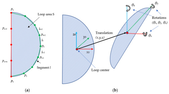
Figure 4.
Lead loop with discretized boundary (a). Roto-translation of the loop area (b).
The calculation of the magnetic flux linkage ϕ in the loop area is then carried out by (11) using the magnetic vector potential A calculated at any point P′(x′, y′, z′) on the roto-translated loop boundary discretized into n point.
For the considered semicircular shape of the loop, assuming that the loop lies in the xy plane, the rectangular coordinates of a point Pk on the semicircle boundary can be expressed by a parameterized curve as:
where r is the semicircle radius and z0 is the height on the vertical axis. The angle uk is identified by n points on the semicircular line defined in the interval [−π/2, π/2]. The tangent is then given by:
Then, m points on the segment line between the first and last point of the semicircle are added to close the loop. For each of the m points, the relative tangent component is chosen accordingly.
The magnetic flux in (11) can be approximated by:
where lk is the length of the k-th line segment between points Pk(xk, yk, zk) and Pk+1(xk+1, yk+1, zk+1) given by , and Atk is the component of the magnetic vector potential tangent to the k-th segment calculated by:
The magnetic flux ϕ and the induced voltage V are calculated for each possible position of the lead loop, applying the roto-translation Formulas (12) and (13).
The accuracy of the program has been tested for validation, considering the simple case of a cubic domain excited by a spatially constant magnetic field. The solution obtained with the proposed procedure is compared with the analytical solution. We considered nine different rotation angles for each coordinate axis, with steps of 40°, for a total of 93 = 729 rotations. Therefore, we need to carry out 729 iterations of the algorithm, one for each position of the lead loop in the computational domain. We considered three possible excitation cases: (#1) Hx = 100 A/m, Hy = Hz = 0; (#2) Hx = 0, Hy = 100 A/m, Hz = 0; (#3) Hx = Hy = 0, Hz = 100 A/m. The considered loop area is a semicircle having a radius equal to r = 11.97 cm. The comparison between the solutions of the analytical method and the one proposed is reported in Table 1 in terms of maximum induced voltage Vmax, where the results obtained are excellent.

Table 1.
Maximum induced voltage Vmax on the lead loop for a spatially constant magnetic field.
4. Results
4.1. DWPT Coils
The proposed method was applied to a DWPT system based on the same short-track architecture as that of the FABRIC Project [34], with an operational frequency of 85 kHz and power transmission up to 10 kW for each vehicle. The coupler was composed using a rectangular GA coil with size lGA = 150 cm and wGA = 50 cm and a rectangular VA coil with size lVA = 50 cm and lVA = 60 cm. The system can operate at a vertical separation distance up to Δz = 20 cm: this value was adopted in all the simulations presented in the following as it represents the worst-case condition on the z-axis. On the VA coil, two ferrite blocks were adopted with rectangular shape of dimensions 15 cm × 25 cm and thickness 0.5 cm. The use of the ferrite block permitted mitigation of the magnetic field and reduction of the negative effect of the metal body of the vehicle on the magnetic coupling between the coils [22]. Both coils were composed using 10 turns. To reduce losses, the coils were assumed to be made with a litz wire. The misalignment between VA and GA coil was Δx on the x direction and Δy on the y direction, as shown in Figure 5.
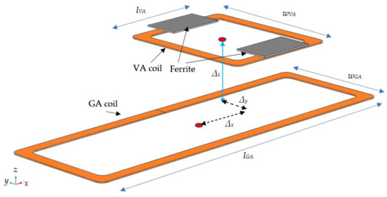
Figure 5.
Electromagnetic configuration of the WPT coil system with a lateral active coil.
To calculate the coil currents, which are the sources of the magnetic field, a realistic configuration of power electronic systems was considered. On the transmitting side, the sinusoidal voltage source of the equivalent circuit was replaced by a full-bridge inverter while the load resistance was replaced by a full-bridge rectifier and lithium battery. The full-bridge inverter was modeled by adopting the FCA76N60 MOSFETs. On the receiving side, a full-bridge diode rectifier was connected at the output of the compensation network to convert the high-frequency voltage to a DC voltage [50]. Schottky diodes were used to reduce conversion losses. In all simulations, the charging power was kept fixed at 10 kW.
4.2. Magnetic Field Calculation
Two simplified types of cars equipped with coils were modeled using computer-aided design (CAD) software. The first model is a small vehicle, while the second model is a large vehicle, as shown in Figure 6. The external dimensions of the vehicles were: la = 3.2 m, wa = 1.75 m and ha = 1.6 m for the small vehicle and lb = 5.2 m, wb = 2.0 m and hb = 2.1 m for the large vehicle. The characterization of the car chassis is very important as it acts as a conductive shield, which significantly modifies the distribution of the magnetic field. For both car models, it was assumed that the chassis was made of aluminum with thickness tch = 2 mm and conductivity σal = 3MS/m. Since the fine discretization of the metal chassis requires a very large number of finite elements to account the skin effect, the vehicle body was modeled by adopting the transition boundary conditions (TBC) [51,52,53,54], which eliminates the finite element discretization inside the metallic layers. TBCs are applied to internal surface boundaries to model the field discontinuity produced by a thin layer of a highly conducting medium.

Figure 6.
Vehicle body: small car (a), large car (b).
The effect of the earth conductivity on the magnetic field distribution at the considered frequency has been neglected as the penetration depth in the earth at 85 kHz is approximately in the range 20–50 m, which is a much greater distance than the coil dimensions.
The magnetic field simulations were carried out by the commercial software COMSOL [55]. Both coils have been modeled using the “Coil” function. The coil currents IGA and IVA obtained from the circuit analysis were imported into COMSOL and injected into the coils as source currents [56]. The whole model considering the large car was discretized into 215,142 tetrahedral elements.
A first analysis was addressed to perform a comparison between the two car models in terms of magnetic field behavior. For this analysis, the VA coil was assumed to be perfectly aligned with the GA coil on x direction Δx = 0 mm while the maximum lateral misalignment was considered on y direction (Δy = 150 mm). Since the aluminum bodyshell acts as a conductive shield, the first step was the calculation of the coil self and mutual inductances for each of the two types of cars. Then, the electrical circuit was solved to calculate the coil current IGA and IVA for both car models. The calculated electrical parameters are reported in Table 2 for Δx = 0 and Δy = 150 mm assuming a fixed transferred power equal to P2 = 10 kW. The corresponding magnetic field distributions on the xz and yz planes are shown in Figure 7. A validation of the proposed numerical approach by measurements can be found elsewhere [30,44].
Table 2.
Lumped circuit parameters.
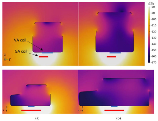
Figure 7.
Magnetic field distribution in dBT for small car (a) and large car (b).
As can be seen, the electrical circuit parameters were not significantly influenced by the vehicle dimensions. On the contrary, with the smaller car there was a significant increase in the magnetic field beside the vehicle where pedestrians might be, due to the possible reduction of the distance between the sidewalk and the coils, and for passengers in the cabin, due to an increase in the magnetic field coming from the apertures in the chassis of the car (i.e., windows) [57,58,59,60,61,62]. Therefore, the small vehicle was selected as the worst-case scenario in the following analysis. To simulate the motion of the vehicle, different positions of the VA coil with respect to the fixed GA coil were considered. Five points were considered for x-axis misalignment (Δx = 100, 200, 400, 500, 600 mm), while the lateral offset was taken as fixed at Δy = 150 mm and the vertical distance was taken as fixed at Δz = 200 mm. The results obtained in terms of electrical quantities are reported in Table 3.
Table 3.
Electrical quantities of the circuit for several positions on the x axis.
The results demonstrates that Position #5 represented the worst case, as a higher current was needed on the GA coil to keep the output power fixed at 10 kW. This condition was selected for the following analysis on EMI in CIEDs.
The magnetic flux density map for Position #5 (Δx = 600 mm, Δy = 150 mm, Δz = 200 mm) is reported in Figure 8. The figure also shows the isolines of the reference levels of the ICNIRP 1998 (Bmax = 6.25 µT) [48] and 2010 (Bmax = 27 µT) [49] guidelines. An exceeding of the reference level can be noted in the area beside the vehicle where pedestrians might be. Since the ISO limit of 188.5 µT is greater than the ICNIRP reference levels, any precautionary measure for the protection of the general public from adverse health effects produced by incident magnetic fields will also be precautionary for EMI in CIEDs, at least for AC magnetic fields. However, EMI in CIEDs can also be produced by induced voltage. Then, the induced voltage on a pacemaker lead can be calculated by adopting the proposed method as described in Section 3.1 and Section 3.2 Specifically, two regions were considered for this calculation: Region #1, which is inside the cabin where the passengers are located, and Region #2, which is beside the vehicle where pedestrians may be, as shown in Figure 9 where the two regions are depicted in green and blue volumes, respectively.
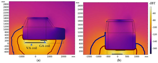
Figure 8.
Magnetic field distribution for the small car and worst case coil misalignment: xz cut-plane (a) and yz cut-plane (b). (Reference levels of the ICNIRP 2010 and 1998 are depicted in thick red and blue lines, respectively).
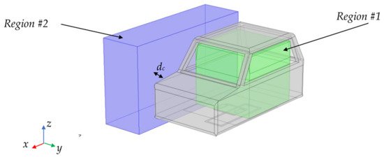
Figure 9.
Regions selected for the calculation of the induced voltage on the lead loop area.
Region #1 coincides with the cabin volume while Region #2 is a parallelepiped volume with length lv = 3 m, height hv = 2 m and width wv = 1 m. The minimum lateral distance from the box to the vehicle body is dc = 15 cm. The proposed algorithm discretizes Region #1 into grid points with 10 steps per axis for a total of 103 = 1000 points. The rotations on the three rectangular axes were performed with steps of θ = 30°; therefore, the maximum error was acceptable as it was around 4% being cos(30°/2) = 0.96 and the number of calculations was limited. The number of rotations for each point and for each axis was equal to 180°/30° = 6 for the symmetry of the semicircle area S; therefore, the total number of rotations per point was 63 = 216. By applying the proposed algorithm for all 1000 points in the Region #1, the total number of roto-translations was 216,000. For each of the 216,000 possible lead loop area positions, the magnetic flux ϕ and hence the induced voltage V were calculated from (10b) and (9), respectively. A similar algorithm was also applied to Region #2. The maps of the calculated rms-induced voltage V are shown in Figure 10 for Region #1 and in Figure 11 for Region #2. The maximum value of the induced voltage V for each lead loop area position was recorded to find the maximum value and then compared to the ISO 14117 limit fixed to the peak-to-peak voltage to Vpp = 510 mV, which for a sinusoidal wave coincides to an rms value of V = 180.3 mV.
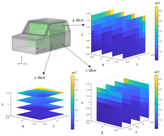
Figure 10.
Maps of the rms-induced voltage V in Region #1.
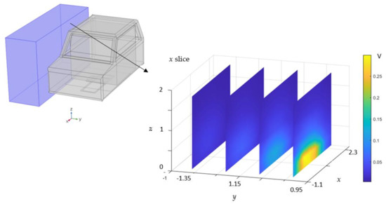
Figure 11.
Maps of the rms-induced voltage V in Region #2.
The results obtained show that for Region #1 inside the cabin, the induced voltage V in any position was well below the maximum voltage limit set by the ISO standard at the considered frequency, with a maximum value of Vmax = 5.4 mV. However, the highest values were found in the right rear corner of the cabin due to the misaligned coil condition and window position. It means that the aluminum car body is a very good shield at 85 kHz and the magnetic field enters the cabin mainly through the windows. Therefore, the points close to the windows, especially those at the bottom, are the most exposed to the magnetic field and consequently to the voltage induced on the lead loop area.
The situation for Region #2 was decidedly worse, where the maximum calculated rms value was Vmax = 314 mV, which greatly exceeds the limit of the ISO standard equal to 180.3 mV as the rms value. As can be seen from the induced voltage distribution, the highest values were obtained near the coils of the WPT system, which is very close to the ground. Although pedestrians are generally standing rather than lying next to the DWPT coils, the induced voltage values are not entirely reassuring and it is advisable to take precautionary measures to avoid any risk for pacemaker wearers and apply magnetic field mitigation techniques [62,63,64].
5. Conclusions
DWPT technology is very attractive for recharging the battery of EVs in motion. However, one of the biggest problems is the emission of a strong magnetic field in the environment which can produce adverse health effects on exposed people and EMI in nearby electronic devices. Here, we performed a deep numerical investigation of EMI in CIEDs produced by a short-track architecture of a DWPT system operating at 85 kHz and delivering 10 kW of power to each EV while recharging. In CIEDs with leads, the EMI is mainly produced by AC magnetic field and induced voltage on the lead loop area. Therefore, first we characterized the behavior of the magnetic field by simulation and then we calculated the induced voltage at the input port of the CIED. For the first aspect, we found the worst-case configuration due to vehicle size and variable position of coupled coils due to EV motion for a DWPT system with a similar configuration as in the FABRIC Project.
To predict the induced voltage on the lead loop area, we presented a new procedure by post-processing the magnetic field obtained from the worst-case coil configuration. We discretized the most critical regions (i.e., cabin and beside the vehicle) in a grid-point cloud with a spatial step of a few centimeters and for each point we applied 216 rotations along the three orthogonal axes of the lead loop area assumed to be semicircular in shape and with an area equal to 225 cm2, according to the ISO 14117 standard. For every position, we calculated and recorded the magnetic flux linked with the lead loop area and then also the induced voltage.
The results obtained are preliminary and by simulation. However, we can observe that pacemaker wearers have no EMI risk inside the passenger cabin, even for a small car without the rear trunk and therefore with more exposed to the magnetic field entering through the rear window. On the contrary, the induced voltage greatly exceeded the ISO 14117 limit in the region beside the vehicle. This is a major problem, especially on sidewalks in urban settings, which can be addressed by adopting precautionary measures and/or mitigation techniques to reduce the magnetic field strength and consequently the induced voltage on the input port of a CIED, which can produce EMI.
Author Contributions
Conceptualization, T.C.; Methodology, T.C.; Software, T.C. and S.C.; Formal analysis, F.M. and M.F.; Investigation, F.M.; Data curation, S.C.; Writing—original draft, F.M. and M.F.; Writing—review & editing, S.C. and M.F. All authors have read and agreed to the published version of the manuscript.
Funding
This research was funded by the Projects of national interest—PRIN2017, Project title “WPT4WID: Wireless Power Transfer for Wearable and Implantable Devices”, under Project no. 2017YJE9XK.
Data Availability Statement
Data available upon reasonable request.
Conflicts of Interest
The authors declare no conflict of interest.
References
- Covic, G.A.; Boys, J.T. Inductive power transfer. Proc. IEEE 2013, 101, 1276–1289. [Google Scholar] [CrossRef]
- Shinohara, N. Power without wires. IEEE Microw. Mag. 2011, 11, 64–73. [Google Scholar] [CrossRef]
- Wang, C.-S.; Covic, G.A.; Stielau, O.H. Power Transfer Capability and Bifurcation Phenomena of Loosely Coupled Inductive Power Transfer Systems. Trans. Ind. Electron. 2004, 51, 148–157. [Google Scholar] [CrossRef]
- Ahmad, A.; Alam, M.S.; Chabaan, R.A. Comprehensive Review of Wireless Charging Technologies for Electric Vehicles. Trans. Transport. Electrific. 2018, 4, 38–63. [Google Scholar] [CrossRef]
- Laporte, S.; Coquery, G.; Deniau, V.; De Bernardinis, A.; Hautière, N. Dynamic wireless power transfer charging infrastructure for future evs: From experimental track to real circulated roads demonstrations. World Electr. Veh. J. 2019, 10, 84. [Google Scholar] [CrossRef]
- Bi, Z.; Kan, T.; Mi, C.C.; Zhang, Y.; Zhao, Z.; Keoleian, G.A. A review of wireless power transfer for electric vehicles: Prospects to enhance sustainable mobility. Appl. Energy 2016, 179, 413–425. [Google Scholar] [CrossRef]
- Choi, S.Y.; Gu, B.W.; Jeong, S.Y.; Rim, C.T. Advances in Wireless Power Transfer Systems for Roadway-Powered Electric Vehicles. IEEE J. Emerg. Sel. Top. Power Electron. 2014, 3, 18–36. [Google Scholar] [CrossRef]
- Mi, C.C.; Buja, G.; Choi, S.Y.; Rim, C.T. Modern Advances in Wireless Power Transfer Systems for Roadway Powered Electric Vehicles. IEEE Trans. Ind. Electron. 2016, 63, 6533–6545. [Google Scholar] [CrossRef]
- Song, K.; Koh, K.E.; Zhu, C.; Jiang, J.; Wang, C.; Huang, X. A Review of Dynamic Wireless Power Transfer for In-Motion Electric Vehicles. In Wireless Power Transfer-Fundamentals and Technologies; BoD—Books on Demand: Norderstedt, Germany, 2016; pp. 109–128. [Google Scholar]
- Mohamed, A.A.S.; Shaier, A.A.; Metwally, H.; Selem, S.I. An Overview of Dynamic Inductive Charging for Electric Vehicles. Energies 2022, 15, 5613. [Google Scholar] [CrossRef]
- Buja, G.; Rim, C.T.; Mi, C.C. Dynamic Charging of Electric Vehicles by Wireless Power Transfer. IEEE Trans. Ind. Electron. 2016, 63, 6530–6532. [Google Scholar] [CrossRef]
- Miller, J.M.; Jones, P.; Li, J.-M.; Onar, O.C. ORNL Experience and Challenges Facing Dynamic Wireless Power Charging of EV’s. IEEE Circuits Syst. Mag. 2015, 15, 40–53. [Google Scholar] [CrossRef]
- Arakawa, T.; Goguri, S.; Krogmeier, J.V.; Kruger, A.; Love, D.J.; Mudumbai, R.; Swabey, M.A. Optimizing Wireless Power Transfer from Multiple Transmit Coils. IEEE Access 2018, 6, 23828–23838. [Google Scholar] [CrossRef]
- Lu, F.; Zhang, H.; Hofmann, H.; Mi, C.C. A Dynamic Charging System with Reduced Output Power Pulsation for Electric Vehicles. IEEE Trans. Ind. Electron. 2016, 63, 6580–6590. [Google Scholar] [CrossRef]
- Suh, N.; Cho, D.; Rim, C. Design of On-Line Electric Vehicle (OLEV). In Global Product Development; Springer: Berlin/Heidelberg, Germany, 2011. [Google Scholar]
- Sun, L.; Ma, D.; Tang, H. A review of recent trends in wireless power transfer technology and its applications in electric vehicle wireless charging. Renew. Sustain. Energy Rev. 2018, 91, 490–503. [Google Scholar] [CrossRef]
- Choi, S.; Huh, J.; Lee, W.Y.; Lee, S.W.; Rim, C.T. New Cross-Segmented Power Supply Rails for Roadway-Powered Electric Vehicles. IEEE Trans. Power Electron. 2013, 28, 5832–5841. [Google Scholar] [CrossRef]
- Ko, Y.D.; Jang, Y.J. The Optimal System Design of the Online Electric Vehicle Utilizing Wireless Power Transmission Technology. IEEE Trans. Intell. Transp. Syst. 2013, 14, 1255–1265. [Google Scholar] [CrossRef]
- García-Vázquez, C.A.; Llorens-Iborra, F.; Fernández-Ramírez, L.M.; Sánchez-Sainz, H.; Jurado, F. Comparative study of dynamic wireless charging of electric vehicles in motorway, highway and urban stretches. Energy 2017, 137, 42–57. [Google Scholar] [CrossRef]
- Huh, J.; Lee, S.W.; Lee, W.Y.; Cho, G.H.; Rim, C.T. Narrow-Width Inductive Power Transfer System for Online Electrical Vehicles. IEEE Trans. Power Electron. 2011, 26, 3666–3679. [Google Scholar] [CrossRef]
- Xiang, L.; Li, X.; Tian, J.; Tian, Y. Crossed DD Geometry and Its Double-Coil Excitation Method for EV Dynamic Wireless Charging Systems. IEEE Access 2018, 6, 45120–45128. [Google Scholar] [CrossRef]
- Lazzeroni, P.; Cirimele, V.; Canova, A. Economic and environmental sustainability of Dynamic Wireless Power Transfer for electric vehicles supporting reduction of local air pollutant. Renew. Sustain. Energy Rev. 2021, 138, 110537. [Google Scholar] [CrossRef]
- Chen, L.; Nagendra, G.; Boys, J.T.; Covic, G.A. Double-Coupled Systems for IPT Roadway Applications. IEEE J. Emerg. Sel. Top. Power Electron. 2014, 3, 37–49. [Google Scholar] [CrossRef]
- Miller, J.M.; Onar, O.C.; White, C.; Campbell, S.; Coomer, C.; Seiber, L.; Sepe, R.; Steyerl, A. Demonstrating Dynamic Wireless Charging of an Electric Vehicle: The Benefit of Electrochemical Capacitor Smoothing. IEEE Power Electron. Mag. 2014, 1, 12–24. [Google Scholar] [CrossRef]
- Lee, K.; Pantic, Z.; Lukic, S. Reflexive Field Containment in Dynamic Inductive Power Transfer Systems. IEEE Trans. Power Electron. 2013, 29, 4592–4602. [Google Scholar] [CrossRef]
- Campi, T.; Cruciani, S.; Maradei, F.; Feliziani, M. Two-Coil Receiver for Electrical Vehicles in Dynamic Wireless Power Transfer. Energies 2021, 14, 7790. [Google Scholar] [CrossRef]
- Driessen, S.; Napp, A.; Schmiedchen, K.; Kraus, T.; Stunder, D. Electromagnetic interference in cardiac electronic implants caused by novel electrical appliances emitting electromagnetic fields in the intermediate frequency range: A systematic review. Europace 2019, 21, 219–229. [Google Scholar] [CrossRef]
- Hikage, T.; Nojima, T.; Fujimoto, H. Active implantable medical device EMI assessment for wireless power transfer operating in LF and HF bands. Phys. Med. Biol. 2022, 61, 4522–4536. [Google Scholar] [CrossRef]
- Cruciani, S.; Campi, T.; Maradei, F.; Feliziani, M. Wireless Charging in Electric Vehicles: EMI/EMC Risk Mitigation in Pacemakers by Active Coils. In Proceedings of the 2019 IEEE PELS Workshop on Emerging Technologies: Wireless Power Transfer (WoW), London, UK, 18–21 June 2019; pp. 173–176. [Google Scholar] [CrossRef]
- Campi, T.; Cruciani, S.; Maradei, F.; Feliziani, M. Pacemaker Lead Coupling with an Automotive Wireless Power Transfer System. IEEE Trans. Electromagn. Compatib. 2019, 61, 1935–1943. [Google Scholar] [CrossRef]
- ISO 14117:2019; Active Implantable Medical Devices—Electromagnetic Compatibility—EMC Test Protocols for Implantable Cardiac Pacemakers, Implantable Cardioverter Defibrillators and Cardiac Resynchronization Devices. ISO: Geneva, Switzerland, 2019.
- Campi, T.; Cruciani, S.; Santilli, G.P.; Feliziani, M. Numerical analysis of EMF safety and thermal aspects in a pacemaker with a Wireless Power Transfer system. In Proceedings of the 2015 IEEE Wireless Power Transfer Conference (WPTC), Boulder, CO, USA, 13–15 May 2015; pp. 1–4. [Google Scholar] [CrossRef]
- Mattei, E.; Censi, F.; Delogu, A.; Ferrara, A.; Calcagnini, G. Setups for in vitro assessment of RFID interference on pacemakers. Phys. Med. Biol. 2013, 58, 5301–5316. [Google Scholar] [CrossRef]
- FABRIC European Project. Available online: http://www.fabric-project.eu/www.fabric-project.eu/index.html (accessed on 16 January 2022).
- Simonazzi, M.; Sandrolini, L.; Mariscotti, A. Receiver–Coil Location Detection in a Dynamic Wireless Power Transfer System for Electric Vehicle Charging. Sensors 2022, 22, 2317. [Google Scholar] [CrossRef]
- Zhao, J.; Zhang, J.; Zhang, Y.; Din, Z.; Juri, J. A Reactive Compensation Method Using Switch Controlled Capacitor for Wireless Power Transfer. In Proceedings of the 2019 IEEE Energy Conversion Congress and Exposition (ECCE), Baltimore, MD, USA, 29 September–3 October 2019; pp. 2112–2117. [Google Scholar] [CrossRef]
- Yan, Z.; Zhang, Y.; Song, B.; Zhang, K.; Kan, T.; Mi, C. An LCC-P Compensated Wireless Power Transfer System with a Constant Current Output and Reduced Receiver Size. Energies 2019, 12, 172. [Google Scholar] [CrossRef]
- Lu, S.; Deng, X.; Shu, W.; Wei, X.; Li, S. A New ZVS Tuning Method for Double-Sided LCC Compensated Wireless Power Transfer System. Energies 2018, 11, 307. [Google Scholar] [CrossRef]
- Zhang, X.; Lai, Z.; Xiong, R.; Li, Z.; Zhang, Z.; Song, L. Switching Device Dead Time Optimization of Resonant Double-Sided LCC Wireless Charging System for Electric Vehicles. Energies 2017, 10, 1772. [Google Scholar] [CrossRef]
- Ali, N.; Liu, Z.; Armghan, H.; Ahmad, I.; Hou, Y. LCC-S-Based Integral Terminal Sliding Mode Controller for a Hybrid Energy Storage System Using a Wireless Power System. Energies 2021, 14, 1693. [Google Scholar] [CrossRef]
- Yang, D.; Won, S.; Tian, J.; Cheng, Z.; Kim, J. A Method of Estimating Mutual Inductance and Load Resistance Using Harmonic Components in Wireless Power Transfer System. Energies 2019, 12, 2728. [Google Scholar] [CrossRef]
- González-González, J.M.; Triviño-Cabrera, A.; Aguado, J.A. Design and Validation of a Control Algorithm for a SAE J2954-Compliant Wireless Charger to Guarantee the Operational Electrical Constraints. Energies 2018, 11, 604. [Google Scholar] [CrossRef]
- Zhang, L.; Li, H.; Guo, Q.; Xie, S.; Yang, Y. Research on Constant Voltage/Current Output of LCC–S Envelope Modulation Wireless Power Transfer System. Energies 2022, 15, 1562. [Google Scholar] [CrossRef]
- Campi, T.; Cruciani, S.; Feliziani, M. Magnetic Shielding of Wireless Power Transfer Systems. In Proceedings of the International Symposium on Electromagnetic Compatibility, Tokyo, Japan, 13–16 May 2014. [Google Scholar]
- Campi, T.; Cruciani, S.; Maradei, F.; Palandrani, F.; De Santis, V.; Hirata, A.; Feliziani, M. Wireless Power Transfer charging system for AIMDs and pacemakers. IEEE Trans. Microw. Th. Techn. 2016, 64, 633–642. [Google Scholar] [CrossRef]
- Cruciani, S.; Campi, T.; Maradei, F.; Feliziani, M. Active Shielding Applied to an Electrified Road in a Dynamic Wireless Power Transfer (WPT) System. Energies 2020, 13, 2522. [Google Scholar] [CrossRef]
- Cruciani, S.; Campi, T.; Maradei, F.; Feliziani, M. Numerical Modeling of Litz Wires Based on Discrete Transpositions of Strands and 2-D Finite Element Analysis. IEEE Trans. Power Electron. 2023, 38, 6710–6719. [Google Scholar] [CrossRef]
- International Commission on Non-Ionizing Radiation Protection. Guidelines for limiting exposure to time-varying electric and magnetic fields for low frequencies (1 Hz–100 kHz). Health Phys. 2010, 99, 818–836. [Google Scholar] [CrossRef]
- International Commission on Non-Ionizing Radiation Protection. Guidelines for limiting exposure to time-varying electric, magnetic, and electromagnetic fields (up to 300 GHz). Health Phys. 1998, 74, 494–522. [Google Scholar]
- Campi, T.; Cruciani, S.; Maradei, F.; Feliziani, M. Wireless charging system integrated in a small unmanned aerial vehicle (UAV) with high tolerance to planar coil misalignment. In Proceedings of the Joint International Symposium on Electromagnetic Compatibility, Sapporo and Asia-Pacific International Symposium on Electromagnetic Compatibility (EMC Sapporo/APEMC 2019), Sapporo, Japan, 3–7 June 2019; pp. 601–604. [Google Scholar] [CrossRef]
- Campi, T.; Cruciani, S.; De Santis, V.; Maradei, F.; Feliziani, M. Numerical characterization of the magnetic field in electric vehicles equipped with a WPT system. Wirel. Power Transf. 2017, 4, 78–87. [Google Scholar] [CrossRef]
- COMSOL Multiphysics. Available online: https://www.comsol.com/ (accessed on 5 February 2022).
- Buccella, C.; Feliziani, M.; Maradei, F.; Manzi, G. Magnetic field computation in a physically large domain with thin metallic shields. IEEE Trans. Magn. 2005, 41, 1708–1711. [Google Scholar] [CrossRef]
- Feliziani, M.; Maradei, F. Edge element analysis of complex configurations in presence of shields. IEEE Trans. Magn. 1997, 33, 1548–1551. [Google Scholar] [CrossRef]
- Feliziani, M. Subcell FDTD modeling of field penetration through lossy shields. IEEE Trans. Electromagn. Compat. 2012, 54, 299–307. [Google Scholar] [CrossRef]
- Feliziani, M.; Maradei, F. Circuit-oriented FEM: Solution of circuit-field coupled problems by circuit equations (2002). IEEE Trans. Magn. 2022, 38, 965–968. [Google Scholar] [CrossRef]
- De Santis, V.; Campi, T.; Cruciani, S.; Laakso, I.; Feliziani, M. Assessment of the Induced Electric Fields in a Carbon-Fiber Electrical Vehicle Equipped with a Wireless Power Transfer System. Energies 2018, 11, 684. [Google Scholar] [CrossRef]
- Ding, P.; Bernard, L.; Pichon, L. Evaluation of Electromagnetic Field in Human Body Exposed to Wireless Inductive Charging System. IEEE Trans. Magn. 2014, 50, 1037–1040. [Google Scholar] [CrossRef]
- Laakso, I.; Hirata, A. Evaluation of the induced electric field and compliance procedure for a wireless power transfer system in an electrical vehicle. Phys. Med. Biol. 2013, 58, 7583. [Google Scholar] [CrossRef]
- Kim, H.; Song, C.; Kim, D.H.; Jung, D.H.; Kim, I.M.; Kim, Y.I.; Kim, J.; Ahn, S.; Kim, J. Coil design and measurements of automotive magnetic resonant wireless charging system for high-efficiency and low magnetic field leakage. IEEE Trans. Microw. Theory Tech. 2016, 64, 383–400. [Google Scholar] [CrossRef]
- Mohammad, M.; Wodajo, E.T.; Choi, S.; Elbuluk, M.E. Modeling and Design of Passive Shield to Limit EMF Emission and to Minimize Shield Loss in Unipolar Wireless Charging System for EV. IEEE Trans. Power Electron. 2019, 34, 12235–12245. [Google Scholar] [CrossRef]
- Cruciani, S.; Campi, T.; Maradei, F.; Feliziani, M. Active shielding design for wireless power transfer systems. IEEE Trans. Electromag. Compat. 2019, 61, 1953–1960. [Google Scholar] [CrossRef]
- Park, J.; Kim, D.; Hwang, K.; Park, H.H.; Kwak, S.I.; Kwon, J.H.; Ahn, S. A Resonant Reactive Shielding for Planar Wireless Power Transfer System in Smartphone Application. IEEE Trans. Electromagn. Compat. 2017, 59, 695–703. [Google Scholar] [CrossRef]
- Cruciani, S.; Campi, T.; Feliziani, M.; Maradei, F. Optimum coil configuration of wireless power transfer system in presence of shields. In Proceedings of the 2015 IEEE International Symposium on Electromagnetic Compatibility (EMC), Dresden, Germany, 16–22 August 2015; pp. 720–725. [Google Scholar] [CrossRef]


Disclaimer/Publisher’s Note: The statements, opinions and data contained in all publications are solely those of the individual author(s) and contributor(s) and not of MDPI and/or the editor(s). MDPI and/or the editor(s) disclaim responsibility for any injury to people or property resulting from any ideas, methods, instructions or products referred to in the content. |
© 2023 by the authors. Licensee MDPI, Basel, Switzerland. This article is an open access article distributed under the terms and conditions of the Creative Commons Attribution (CC BY) license (https://creativecommons.org/licenses/by/4.0/).