Review

Innovative Approaches to Solar Desalination: A Comprehensive Review of Recent Research

Mechanical Power Engineering Department, Faculty of Engineering, Mansoura University, Mansoura 35516, Egypt
*
Authors to whom correspondence should be addressed.
Energies 2023, 16(9), 3957; https://doi.org/10.3390/en16093957
Submission received: 20 March 2023 / Revised: 23 April 2023 / Accepted: 5 May 2023 / Published: 8 May 2023
(This article belongs to the Special Issue Applied Solar Thermal Energy)

Abstract

:
Solar desalination systems are a promising solution to the water scarcity problem since the majority of the earth’s water resources are salty. With the increasing focus on desalination research, many innovative methods are being developed to extract salts from saline water. Energy consumption is a significant concern in desalination, and renewable energy, particularly solar energy, is considered a viable alternative to fossil fuel energy. In this review, we will focus on direct and indirect solar desalination methods, specifically traditional direct solar desalination methods such as solar still and humidification dehumidification (HDH) desalination systems. We will also briefly discuss a recent advancement in the desalination method known as the fogging process, which is a development of the HDH desalination system.

1. Introduction

Access to clean, potable water is crucial for all living beings and is used for various purposes such as drinking, household activities, agriculture, and industrial processes. The annual minimum requirement for an individual’s potable water needs is estimated to be approximately 1000 m3 [1]. When the annual potable water supply for an individual falls below 1000 m3, it is considered a severe crisis, while water stress starts between 1000 m3 and 1700 m3 per person [2]. The impact of water scarcity affects many parts of the world, with approximately 3.7 billion people currently experiencing water scarcity [3]. Unfortunately, this number is expected to rise by almost 2 billion people by 2050 [3]. Consistent and excessive use of potable water resources can lead to an environmental disaster. The Population Action International Institute has estimated that by 2050, potable water sufficiency, stress, and scarcity will be 58%, 24%, and 18%, respectively [4]. Figure 1 and Figure 2 illustrate the global potable water scarcity and stress, respectively, in 2007 and 1995/2025 [4,5]. The demand for potable water has doubled from almost 4.2 million m3 in the past 50 years to 30% of the accessible potable water supply by 2000, with estimates that it will reach 70% by 2025 [2]. This consumption pattern creates a significant disparity between developed and developing countries, with Egypt’s daily potable water consumption being less than 0.2 m3 per person in contrast to Canada’s 0.274 m3 per person in 2004 [6]. Figure 3 depicts the daily use of potable water per person in 2010 and highlights the vast gap between developed and developing countries [7].
According to The United Nations Children’s Fund (UNICEF), approximately 884 million people utilize contaminated potable water. Nearly 60% of people were provided with improved potable water via artificial means for drinking by public standpipes, boreholes, protected springs, household connections, rainwater and a protected dug well [4]. Figure 4 indicates the global consumption of improved potable water in 2008 [8]. The aforementioned causes push researchers to provide a viable solution for water scarcity. One of these solutions is desalination. Nowadays, the overwhelming majority of nations depend mainly on desalination. Figure 5 indicates the amount of freshwater that could be produced using desalination. From this graph, we can observe that some desalination techniques could offer up to 106 m3/d.

2. Method of Desalination

The main concept of desalination is removing salts from water and it involves two main methods:
  • Thermal desalination: works by vaporizing the saline water to separate the salt and then condensing the vapor. Therefore, heat is considered the main driving force to separate water from salts, such as multi-effect desalination (MED), the humidification–dehumidification method (HDH) and multi-stage flash desalination (MSF) [9]. The main merit of thermal methods is using low-grade energy, flexibility and a simple design. This process can be powered by solar energy.
  • Membrane distillation: water vapor is forced to pass through a membrane, leaving salt on one side. The main advantage of the membrane method is mass production. However, the main issue of desalination is reducing the energy required and increasing the dependency on renewable energy as well.
  • Other methods such as chemical approaches, such as ion exchange, gas hydrate, and liquid-to-liquid extraction, differ greatly from thermal and semi-permeable membrane desalination. Ion exchange, for example, requires expensive chemicals and is only practical for treating low-saline water.
Desalination also provides low-cost potable water between 0.5 USD/m3 and 1 USD/m3 [10]. The global distribution of desalination technologies used between 2013 and 2014 is shown in Figure 5. Thermal desalination provides a great capacity of potable water and can be classified into:
  • Multi-stage flash (MSF).
  • Multi-effect evaporation (MEE) or multi-effect desalination (MED).
  • Thermal or mechanical vapor compression.
The MSF technique depends on the evaporation and condensation of water vapor. The evaporation process is carried out by bulk liquid boiling and lowering its pressure. The heat of condensation is used to preheat saline water in each stage. Approximately 40% of desalination capacity results from multi-stage flash. Multi-effect evaporation (MEE) or multi-effect desalination is similar to MSF but the vapor is condensed in the next successive stage for utilizing the heat of condensation to produce more vapor. It is not widely used because of problems concerning scaling of heat transfer tubes. However, it has more attention due to its high efficiency. Lowering the pressure in each successive stage increases the performance of MEE. The advantages of MEE are that it gives the flexibility to manage for the high- or low-temperature setting and consequently reduces the scaling of corrosion. However, scaling is still the main obstacle for MEE. The main difference between MSF and MEE is that saline water is heated and evaporated by boiling in MEE, which results in forming scaling on the surface of the tubes, meanwhile, saline water is heated without boiling in MSF, and then the evaporation process occurs due to lowering the pressure in the chamber and thus reducing the scaling on the surface of the tubes [11].
Vapor compression desalination processes depend on the reduction in pressure to drive evaporation. Vapor is compressed by either a mechanical compressor (MVC) or steam ejector (thermal vapor compression, TVC) to supply heat of evaporation [11]. Mechanical vapor compression systems generally have a single stage, while TVC systems have multi-stages. The performance of TVC increases with increasing stages. Finally, vapor compression systems are utilized for small to medium requirements [11]. Membrane desalination processes are also crucial technologies for industrial desalination. It can be categorized to reverse osmosis (RO) or electric dialysis (ED). Reverse osmosis relies on increasing the pressure of the saline water to force it to pass through a membrane separating the solute on one side and solvent on the other side. ED processes depend on electricity for separating by a specific ion-exchange membrane, RO is used mainly for large-scale desalination, and both RO and ED can be applied in case of low-salinity-water desalination.

3. Solar Desalination Techniques

The distinction between direct and indirect solar techniques is that solar heat is used to evaporate the saline water, in the former, directly, and, in the latter, indirectly. Regarding indirect solar systems, solar radiation is converted to electricity by photovoltaics, in other words, heat from the sun is not applied directly to evaporate water. Most thermal desalination systems employ different types of solar collectors such as MSF, MED, TVC, and MD, whereas ED and RO techniques are integrated into PV systems. ED and RO are mostly coupled with wind energy to provide electricity requirements [12]. Figure 6 indicates the categories of solar desalination systems.

4. Review of Traditional Direct Solar Desalination Methods
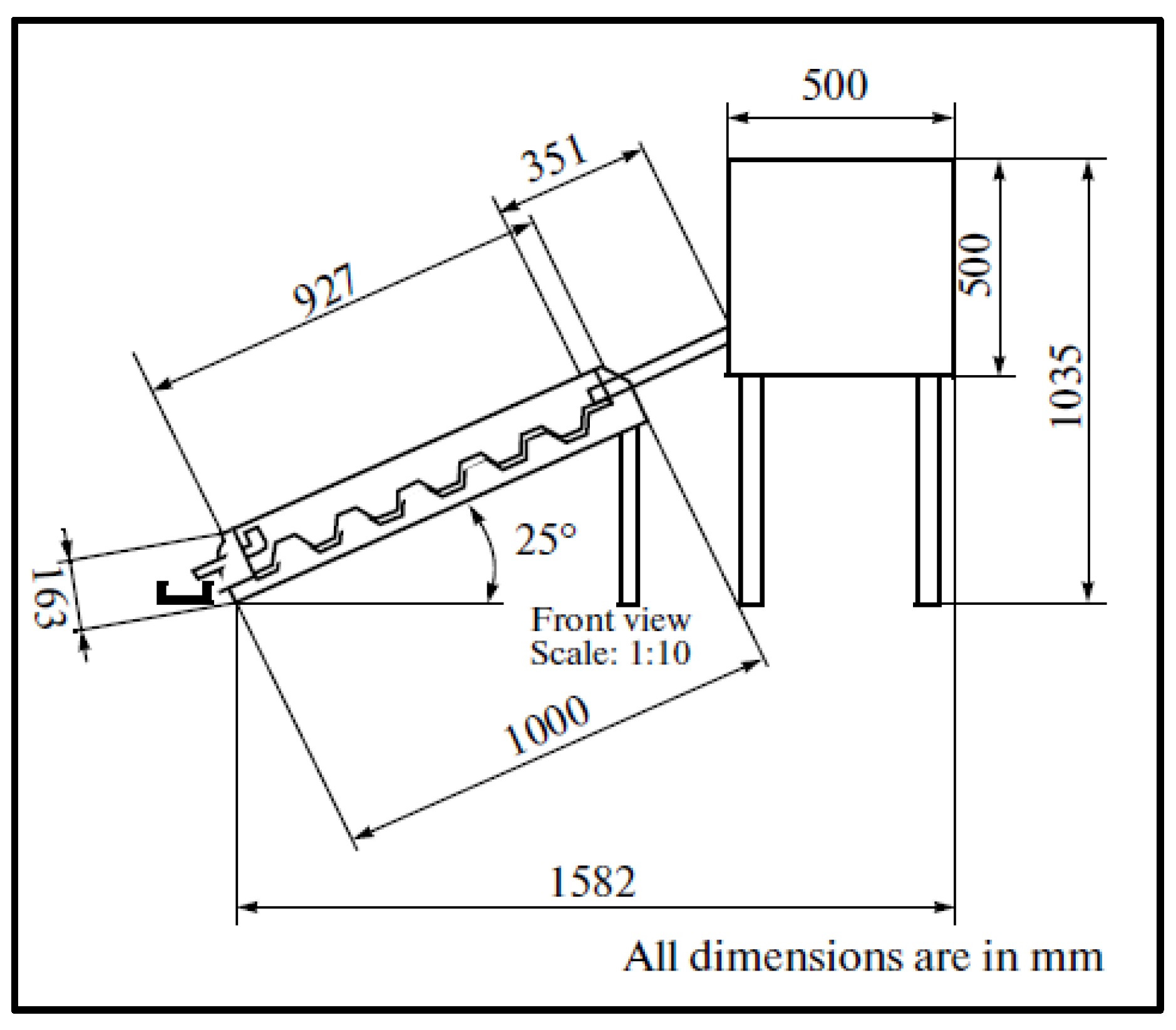
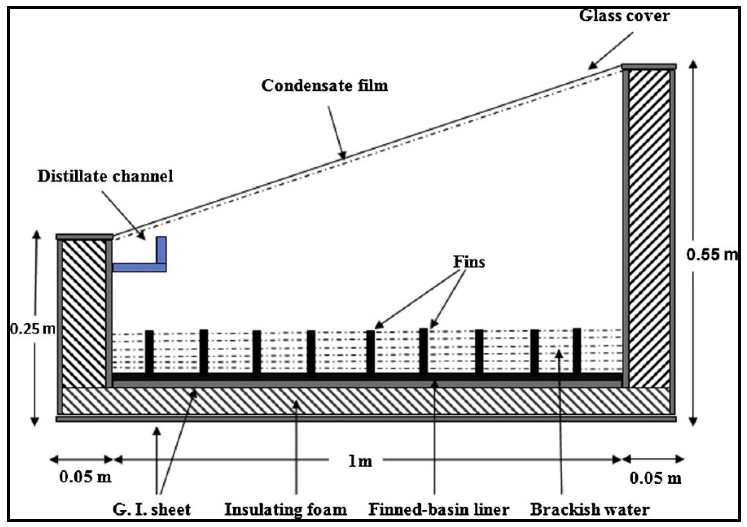
4.1. Solar Still

Alaian et al. [13] investigated experimentally the productivity of solar still augmented with pin finned wick and compared the result with conventional solar still. The area of the basins was 80 × 125 cm, while the horizontal glass cover slope was 17° horizontal with a 4 mm thickness. They used a pinned finned wick with a diameter of 1 cm and a height of 9 cm as shown in Figure 7 so that the effect of the capillary tube could be significant. Solar radiation, ambient temperature and the temperatures at various locations in the systems are recorded under different weather conditions. The results show that the system efficiency increases to 55% and the water productivity to more than 23% compared to the conventional one. The increase in productivity was limited to 11.53% using a wick fin due to the fluctuations of solar radiation. The performance of solar still varies with the change in ambient conditions.
Rajaseenivasan et al. [14] studied experimentally and theoretically the performance of a glass basin solar still. They divided the basin into two sections by a glass plate as shown in Figure 8. The lower one is assigned for preheating the saline water and provided with hollow rectangular fins, which were filled with an energy-storing material. The upper section was used for evaporating water. Feed water enters the preheater section and is pre-heated by the absorber plate before entering the upper section through a small channel. The depth of the preheater section could be changed from 2 cm to 8 cm with the aid of the glass plate. The effect of preheated section depth on the still performance and productivity was investigated as well as the type of energy-storing material. The results showed that daytime productivity is adversely affected by increasing water depth contrary to nighttime. The peak productivity of 3.61 kg/d is achieved when the charcoal material is applied. The daily productivity of distillate water increased from 3.12 to 3.25 kg/day by reducing the depth of the preheater from 8 cm to 2 cm. It was found that the maximum enhancement in the distillate water was 26.74% for river sand, 29.3% for metal scrap and 33.7% for charcoal.
Kabeel et al. [15] studied experimentally and theoretically the performance of stepped solar still and compared their results with the conventional still as shown in Figure 9. Wicks were added to the vertical sides of trays to increase productivity. The effect of the depth and width of the trays of stepped solar still on the performance and productivity of the solar still was investigated. The feed water was preheated using an evacuated tube solar water heater to enhance the productivity of the stepped solar still. The results indicated that the maximum performance reached 57.3% using trays of 5 mm depth and 120 mm height. Additionally, it was noticed that preheating inlet water to the solar still increases slightly the productivity and reduces the efficiency to half. The increase in productivity of stepped solar still using wick on the vertical sides ranges from 3% to 5%. The cost of distillate per liter was 0.039 USD for the stepped solar collector and 0.049 USD for the conventional solar still with daily efficiency of 53% and 33.5%, respectively.
Kabeel and Mohamed [16] studied the performance of solar still using PCM as a thermal storage medium as shown in Figure 10. The investigation was carried out experimentally by fabricating two solar stills. The first is conventional and the second is solar still with PCM. The experimental results show that the daily productivity for solar still with PCM is higher than that of the conventional solar still. The daily freshwater productivity reached 7.54 L/m2 compared to 4.51 L/m2 for the conventional solar still. Finally, the cost of both units per liter was approximately the same (0.03 USD for solar still with PCM and 0.032 USD and conventional solar still).
Samuel Hansen et al. [17] studied experimentally the performance analysis of inclined solar still using different new wick materials and wire mesh. They used wood pulp paper wick, wicking water coral fleece fabric and polystyrene sponge with different designs of the basin (inclined solar still with flat absorber, stepped flat plate and mesh wire flat plate) as shown in Figure 11. They studied the effect of different configurations of the basin shape and wick materials on productivity and efficiency. The maximum yield reached 4.28 L/d for water coral fleece fabric when used with a wire mesh stepped absorber plate. The daily productivity increased by 71.2% for water coral fleece fabric with a wire mesh stepped absorber plate.
Anburaj et al. [18] studied experimentally the performance of an inclined still using rectangular grooves and ridges in the absorber plate as shown in Figure 12. They investigated experimentally the effect of declination angle with horizontal on the performance of the system. They tested a south-oriented absorber plate with 35°, 30° and 25° to the horizontal. In addition, they performed a comparison of the effect of the wicking materials such as (black cotton cloth, jute cloth, and waste cotton pieces) on productivity and efficiency. The effect of placing porous materials such as (clay pots) and energy-storing materials such as (mild steel pieces) by placing them in grooves was investigated. The results showed that the productivity reached a peak of 3.77 L/d at an angle of 30° among the angles tested. As a result, the best-inclined basin angle for the India location was recommended to be 30°. The productivity of solar still increased to 4.21 L/d when the black cotton cloth was applied.
El-Sebaii and El-Naggar [19] examined the performance of finned basin solar still as shown in Figure 13 and compared the outputs with another flat basin solar still. They used a wide range of liner materials as fins. Validation of the mathematical model was carried out using one experimental case. Further, a cost analysis was performed based on a year-round analysis. The outputs indicated that the average annual yield of the finned still reached 1898.8 L/m2 for the year when compared to conventional solar still with 1467.4 L/m2. Applying various fin materials did not enhance the performance greatly. The production cost was 0.28, 0.21 and 0.20 LE/l for copper, glass, and mica compared to 0.31 LE for the conventional type.

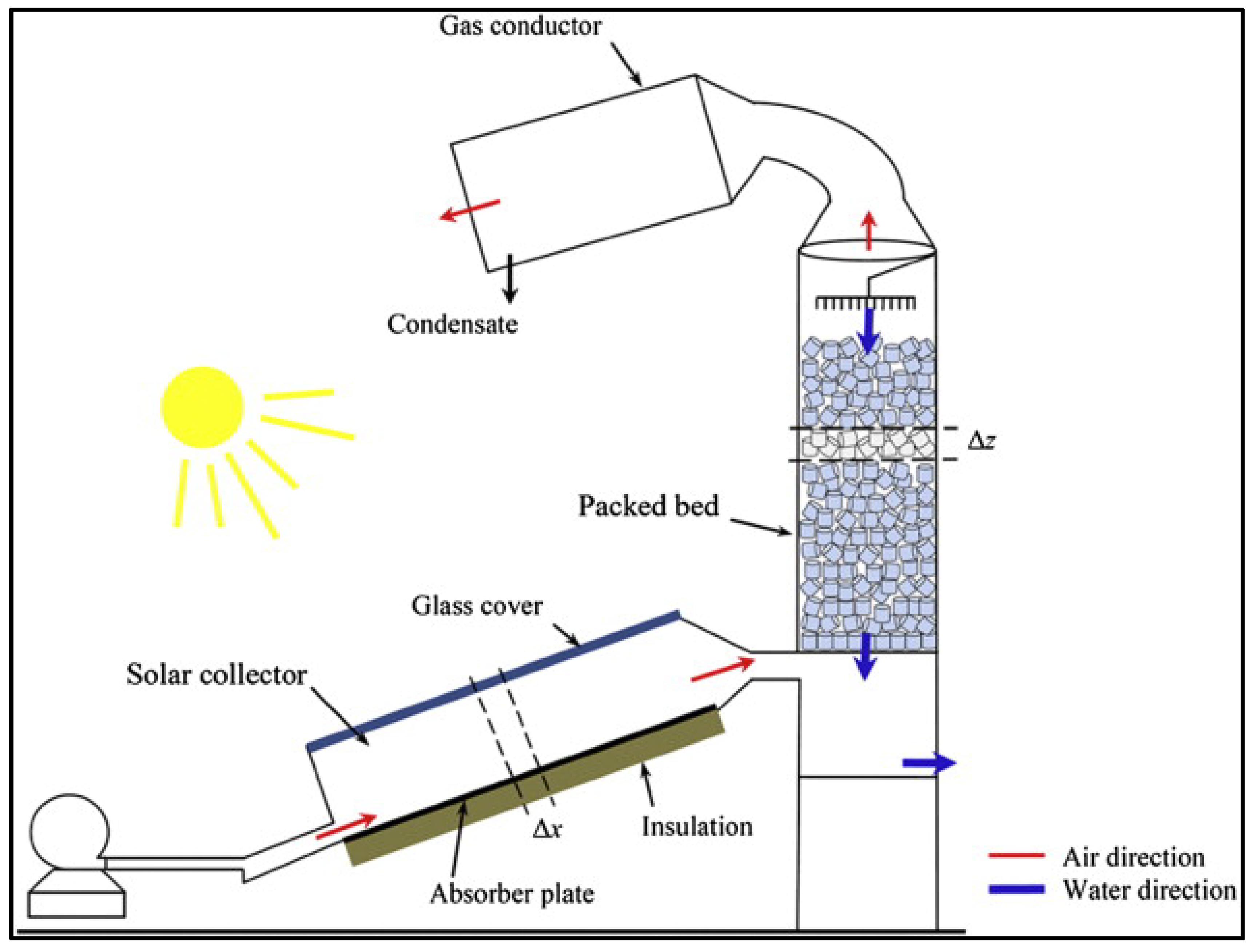
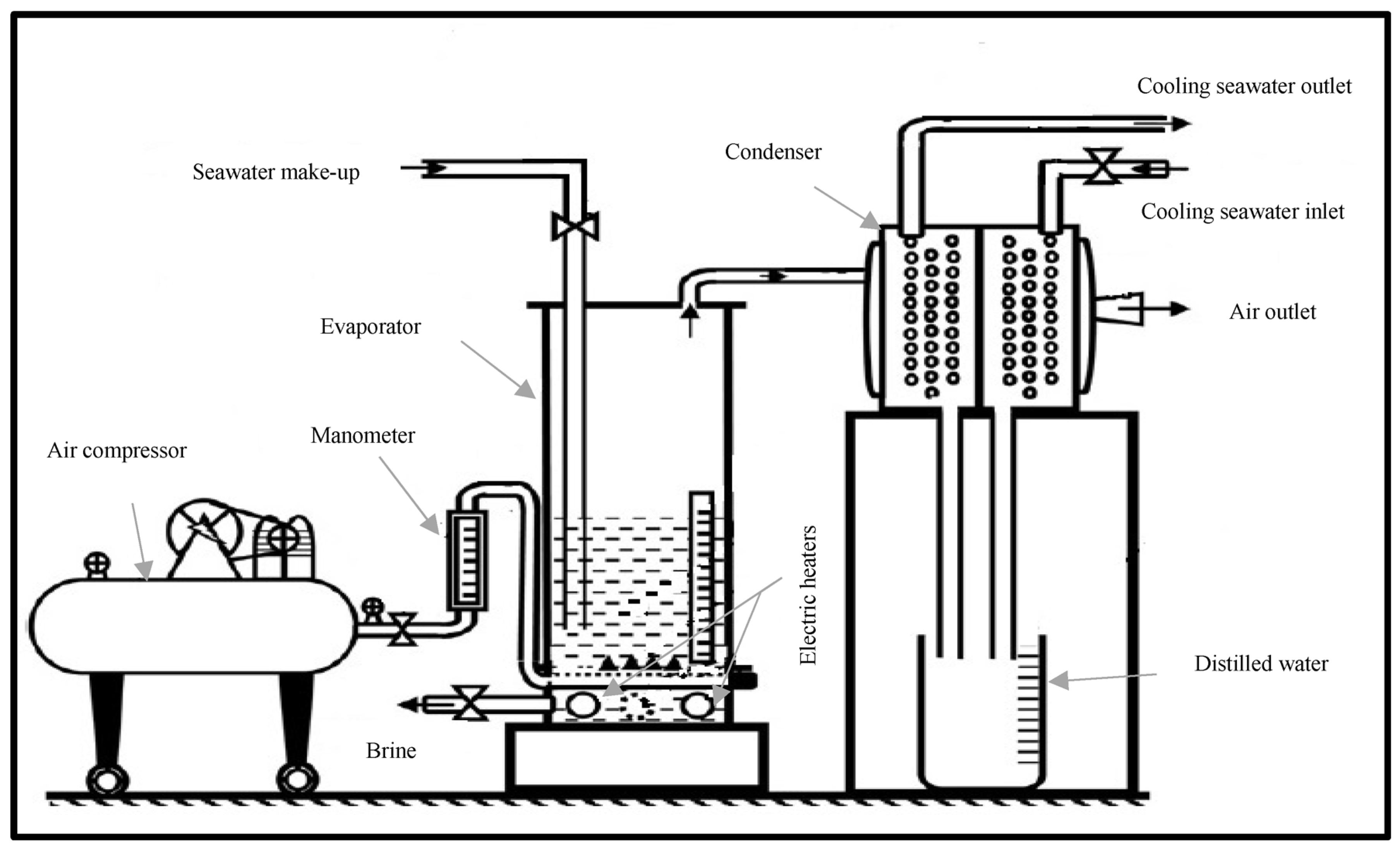
4.2. Solar Humidification De-Humidification Systems

Desalination is a natural process that occurs daily. In the morning, the sun heats saline ocean water, which evaporates and humidifies the surrounding air. Humidified air rises, and the vapor condensed in the sky forms clouds, which drop in the form of rain causing dehumidification of air. Therefore, humidification–dehumidification (HDH) desalination processes are naturally found. The synthetic HDH desalination process depends on the same idea.
The HDH desalination process depends mainly on three components
  • The heating source—heat is supplied to saline water.
  • The humidifier—at which the air is humidified.
  • The dehumidifier—at which vapor condenses from the air [20].
Firstly, the air is humidified by spraying saline water in the air stream, then the air is dehumidified by a condenser that holds saline cold water for the preheating process. HDH process is a promising technique for desalination. This method is suitable for saline seawater desalination. There are many advantages to these types such as simplicity, compact design, low operating costs, flexibility in productivity and capability to use low-grade thermal energy [20]. In these methods, saline water pretreatment is required to prevent scaling and fouling of the humidifier.

4.2.1. Classification of HDH Systems

HDH desalination systems are categorized into three broad classifications. The first category is based on the source of thermal energy used such as nuclear, solar, wind and geothermal. The second category is based on cycle configurations. For instance, some HDH systems use open-air, closed-water cycles (OACW) and closed-air, open-water cycles (CAOW). Other systems use open-air, open-water cycles (OAOW), but it has low efficiency and productivity. The third category is based on either air or water being heated or not.

4.2.2. Open-Air, Closed-Water (OACW) Cycle, Water Heater Systems

Heated saline water is pumped to the humidifier section where the air is delivered in cold streams to get heated and humidified. The evaporation process results in the cooling of saline water by the absorption of latent heat and air humidification. Then, the air is passed through a condenser. At this point, the air is dehumidified, and the condensate is collected. In these systems, the condensation process may be achieved by cooling streams of the saline water out of the evaporation process and this has the advantage of using the heat of condensation to preheat saline water before entering the heater again. Unfortunately, one disadvantage of the OACW cycle is that when the humidification process does not cool the sprayed saline water sufficiently, the saline water temperature at the inlet of the condenser is higher, resulting in lower air dehumidification and lower distilled water production [11].

4.2.3. Closed-Air, Open-Water (CAOW) Cycles, Water Heater Systems

In these systems, the air is circulated into the falling hot saline water in the evaporation section. The air is heated and humidified by the heated saline water before entering the condenser and getting dehumidified. Finally, the air is recirculated by entering the humidifier section again. The condensation process is achieved by saline seawater, which is preheated before entering the heater. The productivity of such systems is high. However, the power required for air circulation is higher. Experimental data collected from previous research show that the efficiency of (CAOW) with natural circulation systems is better than forced circulation systems [11].

4.2.4. Closed-Air, Open-Water (CAOW) Cycles, Air Heater Systems

The air is heated in the heater reaching between 80 and 90 °C and then enters the humidifier section, where it is humidified and cooled by the saline water. The main disadvantage of these systems is that higher energy consumption is required compared to water-heated systems. In air-heated systems, the air heats the water in the humidifier and this energy is not subsequently recovered from the water. However, in water-heated systems, the water stream is cooled in the humidifier and heat is recovered in the air stream.
Sharshir et al. [21] constructed a hybrid desalination system of an HDH unit integrated with four solar stills. They used an evacuated tube solar collector for heating feed saline water. Figure 14 shows the configuration of the whole system. Firstly, saline water is pumped from a cold saline water tank to the dehumidifier section for preheating before entering the solar collector. Heated saline water is sprayed in the humidifier section by a circulation pump and a blower is used to circulate the air in a closed loop. For boosting the yield, brine water that remains in the humidifier section is allowed to pass into four solar stills. Some of the saline water found in the tank is drawn to individual solar still so that they can compare the degree of productivity enhancement. It was found that the performance of each solar still reached 90%, while the productivity of the solar stills integrated with the system increased by 200% compared to conventional solar still. Moreover, the results showed that the daily productivity of the hybrid system was 66.3 kg/d with GOR of 3.18. Finally, the cost of the distillate water was 0.034 USD/kg.
Zubair et al. [22] studied the impact of geographic sites and feed saline water levels on the performance of an HDH desalination setup coupled with an evacuated tube solar heater. Air was circulated in a closed loop while the water loop was opened. Their setup involved different capacities of the evacuated tube solar heater. They found that the ratio between air and water rates should be 1.8 to maximize the performance. The system could reach maximum productivity in summer. Additionally, the cost ranged from 0.032 USD/kg to 0.038 USD/kg according to the location. Nematollahi et al. [23] investigated experimentally and theoretically the efficiency of an HDH desalination system coupled with a solar air collector. Their study investigated the impact of humidifier dimensions, entrance air temperature and the tower radius. They found that as the humidifier radius increases, the exergtic efficiency increases. Further, raising inlet air temperature responded negatively to system efficiency. Amer et al. [24] established an HDH desalination system. Both air and water were open loop circulated as highlighted in Figure 15. An air blower is applied to pass air through the flat plate solar collector and the air is in the humidifier section, which is a packed bed, and water is sprayed vertically downward. As a result, the air is heated and humidified before entering the dehumidifier section, where it is dehumidified by atmospheric air. Finally, the condensate is collected. They investigated theoretically and experimentally the efficiency of this unit. The findings demonstrated that productivity increased with increasing mass flow rates, whereas rising water temperatures at the humidifier entrance increases the humidity ratio between the entrance and the exit of the condenser. Furthermore, the productivity peaked at 5.8 kg/h using wooden slates packing in the humidifier section with forced air circulation. Finally, it was remarked that with higher saline water temperature, natural air circulation is preferable.
Zhani and Ben Bacha [25] established a solar HDH desalination system. The main system setup involved the evaporator and the condenser in the same unit as shown in Figure 16. Their system comprised air and water solar heaters, a humidification unit, an evaporation tower, and a condenser. Feed saline water enters the condenser and then the solar collector for heating. After that, it is pumped into the dehumidifier section. Meanwhile, the air is propelled by a fan to pass through the solar air collector entering the humidifier. Consequently, the air is heated and dehumidified before entering the condenser. Part of the hot saline water evaporates in the evaporator section. Finally, the dehumidified air gets out from the condenser to the fan. Additionally, the impact of the weather conditions on the performance of the system is studied. The outputs indicated that the summer season involved maximum productivity. Additionally, no mentioned effect of both solar insolation intensities and ambient temperatures on the temperature slopes at various locations in the system had been noticed. Yuan and Zhang [26] developed a mathematical model for a solar HDH desalination system. The system contained an air and water-closed circulation loop. They found that increasing the water mass flow rate reduces system productivity.
Al-Hallaj et al. [27] built a solar HDH desalination system. The air loop was closed and saline water was heated using either a solar flat plate heater or an electric heater, air was naturally circulated in one experiment and was circulated using a fan in another experiment. Saline water was preheated using the latent heat of condensation. Their results showed that certain values of saline water rate maximize productivity. Further, forced air circulation had no mentioned effect on the system productivity at a high temperature, approximately 70 °C, while forced air circulation had a superior impact at a low temperature. Therefore, increasing air velocity was recommended at a lower temperature, approximately 50 °C.
Yamali and Solmus [28] investigated the performance of a solar HDH desalination system. Their setup involved a humidifier, dehumidifier, two passes solar air heater and a water storage tank in addition to a solar evacuated tube water heater type. The outputs demonstrated that increasing the initial water temperature in the storage tank enhances the system’s productivity. The saline water flow rate and mass flow rate of cooling water also increase the productivity of the system as well. However, boosting the air flow rate had no significant effect. The performance experienced a 15% decrease when the two passes solar air heater was not applied to the system.
Orfi et al. [29] studied the design and construction of a solar HDH desalination unit that applied a wetted wall vertical humidifier. Their system consisted of an evaporator, condenser, two solar heaters, and the wetted type humidifier. Their mathematical model also included heat and mass transfer analysis in different components. Their results showed that certain values of saline water rate maximize productivity. El-Agouz [30] performed an experimental and theoretical study to determine the effect of a bubble-column humidifier on performance. Air enters slots beneath the water level in an evaporator by a compressor. The evaporator contains electric heaters. As the mixture heats, the air is humidified and rises upwards from the evaporator to the condenser which is run by cold seawater. As a result, the air is dehumidified and released from the condenser. The condensate and brine are collected. A manometer is fixed in the air path and a stem is fixed in the evaporator to measure the pressure of the air and the level of saline water. His experimental work investigated the effect of saline water temperature and the injection of airflow rate into the water on the performance of the system. His outputs highlighted that the yield increases with the increase in saline water flow rates, whereas decreases with increasing airflow rate. However, the impact of the water level was less significant on the productivity of the system. The system productivity reached 8.2 kgw/h at a saline water temperature of 86 °C and an air mass flow rate of 14 kga/h. Figure 17 indicates the experimental setup of the system.
Tow and Lienhard [31] investigated theoretically and experimentally the design of a bubble-column dehumidifier. As shown in Figure 18, moist warm air is injected through a porous stainless steel cartridge sprager. Air bubbles are created and they are cooled by insulated rubber tubing. As a result, water vapor is condensed and dehumidified air is out from an upper hole. They found that decreasing the coil area decreased the effectiveness of the dehumidifier and raised the heat flux. Similarly, increasing the airflow rate and temperature resulted in the same effect on heat flux and effectiveness. However, there was not any significant effect on both column heights or the number of bubbles. Finally, the air gap beneath the column liquid boosted the heat transfer.
Muthusamy and Srithar [32] established a solar HDH desalination system that used inserts in the air heater to enhance heat transfer and system performance. They tested three types of inserts namely, cut-out conical tabulators with fins, the short length of twisted tape with tapered form and half-perforated circular inserts with different orientation angles. Further, they used two types of packing materials sawdust and gunny bag to increase the rate of heat transfer.
They found an approximately 45% increase in system productivity with the twisted tape of short length with a pitch ratio of 3 in the air heater, gunny bag in the humidifier and spring in the dehumidifier. For one hour operating period, the productivity reached 0.67 kg per 0.0597 m2 of the air heater. They investigated both the exergy and energy efficiency of the system, which reached 38% and 44%, respectively. They concluded that the enhancement of the heat transfer reached 9 times as compared with the conventional one. Srithar and Rajaseenisaan [33] constructed experimentally an HDH system integrated with a solar air heater, which contains tabulators and a bubble-column humidifier. They investigated the humidifier performance with preheated air from the solar heater and without it. Their results showed that preheating air increased the specific humidity of the air. Additionally, they investigated the effect of saline water depth and mass flow rate when the humidifier was integrated with the solar heater to optimize performance. The tabulator inserts increased specific humidity to 0.187 kgw/kga compared to 0.11 kgw/kga without it. Consequently, the productivity reached 20.61 kg/m2·d.
Li et al. [34] developed an HDH desalination system connected to an evacuated tube solar air heater as shown in Figure 19. They constructed the system with open-air and closed saline water circulation. Air is pumped to the solar heater and then the humidifier where saline water is sprayed by pump 1 from tank 1. The air is humidified and unevaporated water returns to tank 1. Heated air enters the condenser which is cooled and dehumidified by a closed loop of cold water. The cold water is circulated by pump 2 and the condensate is collected at tank 3. The results showed that increasing spraying rates in the humidifier from 9 °C to 27 °C enhance the water content from 89% to 97% and air temperature at the humidifier exit from 35 °C to 42 °C, respectively. The maximum productivity was 1000 kg/d.
Yamali and Solmus [35] developed a theoretical model for solar-powered HDH units to study the impact of weather conditions, kinds of air solar collectors, operating conditions and other design parametric variables. Their system consisted of a humidifier unit, storage tank, dehumidifier and two passes flat solar air collector. Their setup utilized heated air with open circulation and unheated saline water with a closed loop. The results showed that 8% increase in the system productivity when using a double-pass flat plate solar air heater compared with a single-pass one. However, it was observed that the system productivity decreased by 30% without the solar heater. Further, the outputs showed that nearly 0.02 kg/s of air flow rates achieve the maximum productivity for the same saline water. Moreover, increasing both saline water mass and initial saline water temperature in the tank storage increased significantly the system performance. They found that the efficiency of the system integrated with the double glass flat plate solar air heater is not affected by wind speed compared to the single one.
Guofeng et al. [36] studied experimentally a pilot plant of an HDH desalination system powered by a 100 m2 evacuated tube solar air heater, 12 m2 evacuated tube solar water heater, humidifier unit and dehumidifying exchanger. Both pre-treatment and post-treatment processes were performed to get potable water output. They found that the productivity peaked at 1200 kg/d, at an average solar intensity of 550 W/m2. The temperature of the air at the solar heater outlet reached 118 °C with average solar radiation of 760 W/m2, moreover, the air temperature ranged from 40 °C to 55 °C and the relative humidity changed between 80% and 90%. They conducted an economic analysis which resulted in 2.7 USD/m3 of distilled water.
Zhani [37] investigated theoretically and experimentally a solar-powered HDH desalination system. His system was composed of a flat plate solar water collector, packed pad humidifier unit and dehumidifier. His results showed that there is an optimum value of the saline water mass flow rate, approximately 0.4 kg/s, at which the Gained Output Ratio (GOR) is maximized. He also investigated the efficiency of the flat plate solar water collector. He concluded that increasing the saline water mass flow rate increases the efficiency of the solar collector. However, increasing the inlet saline water temperature decreases the efficiency of the solar collector. Moreover, he concluded that low solar radiation intensity decreases thermal efficiency. To summarize the previous literature review, Table 1 compares the properties and performance of the various HDH systems.

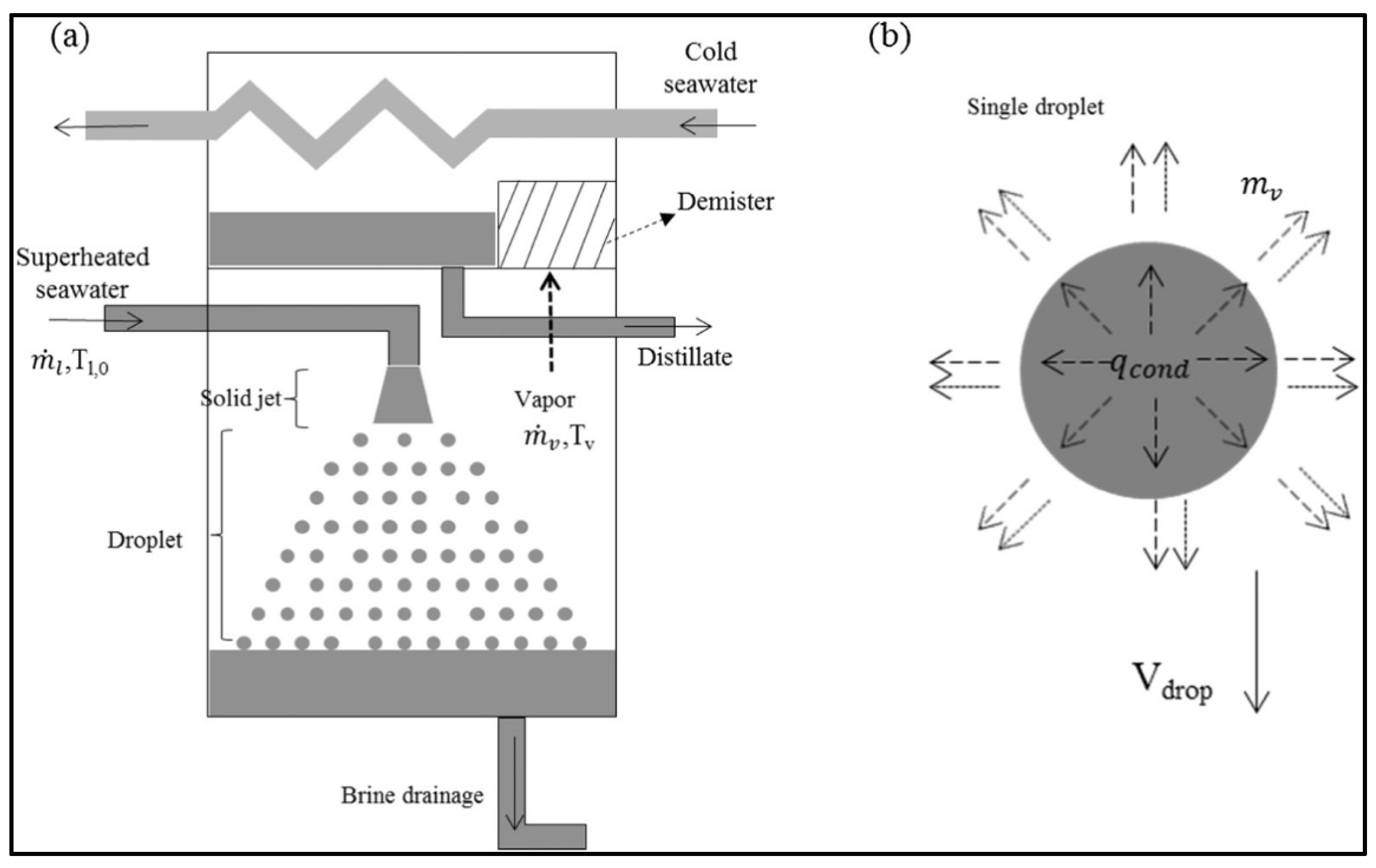
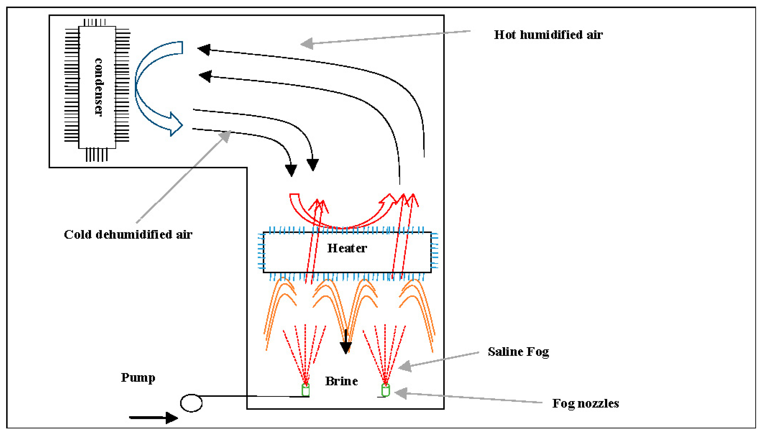
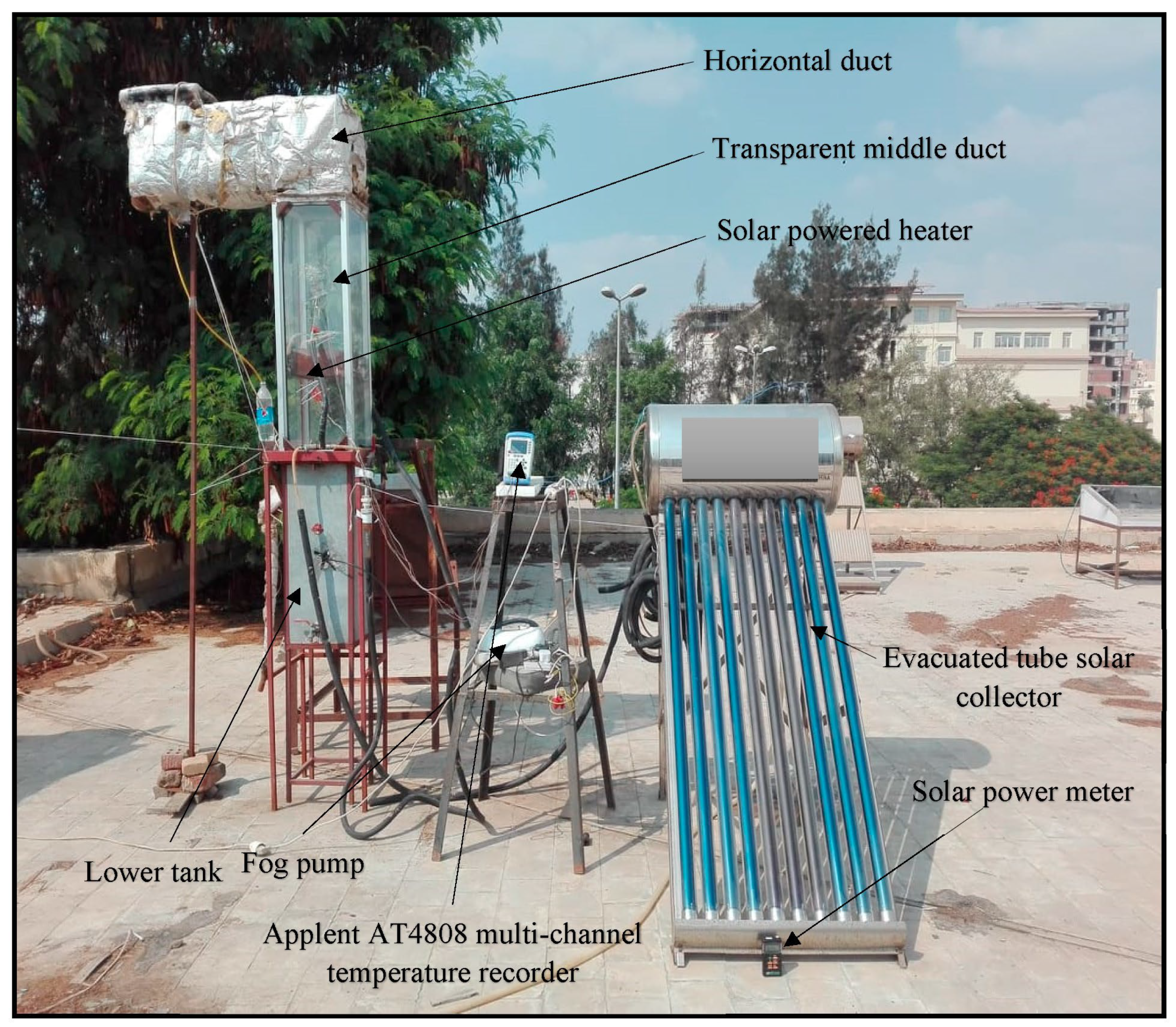
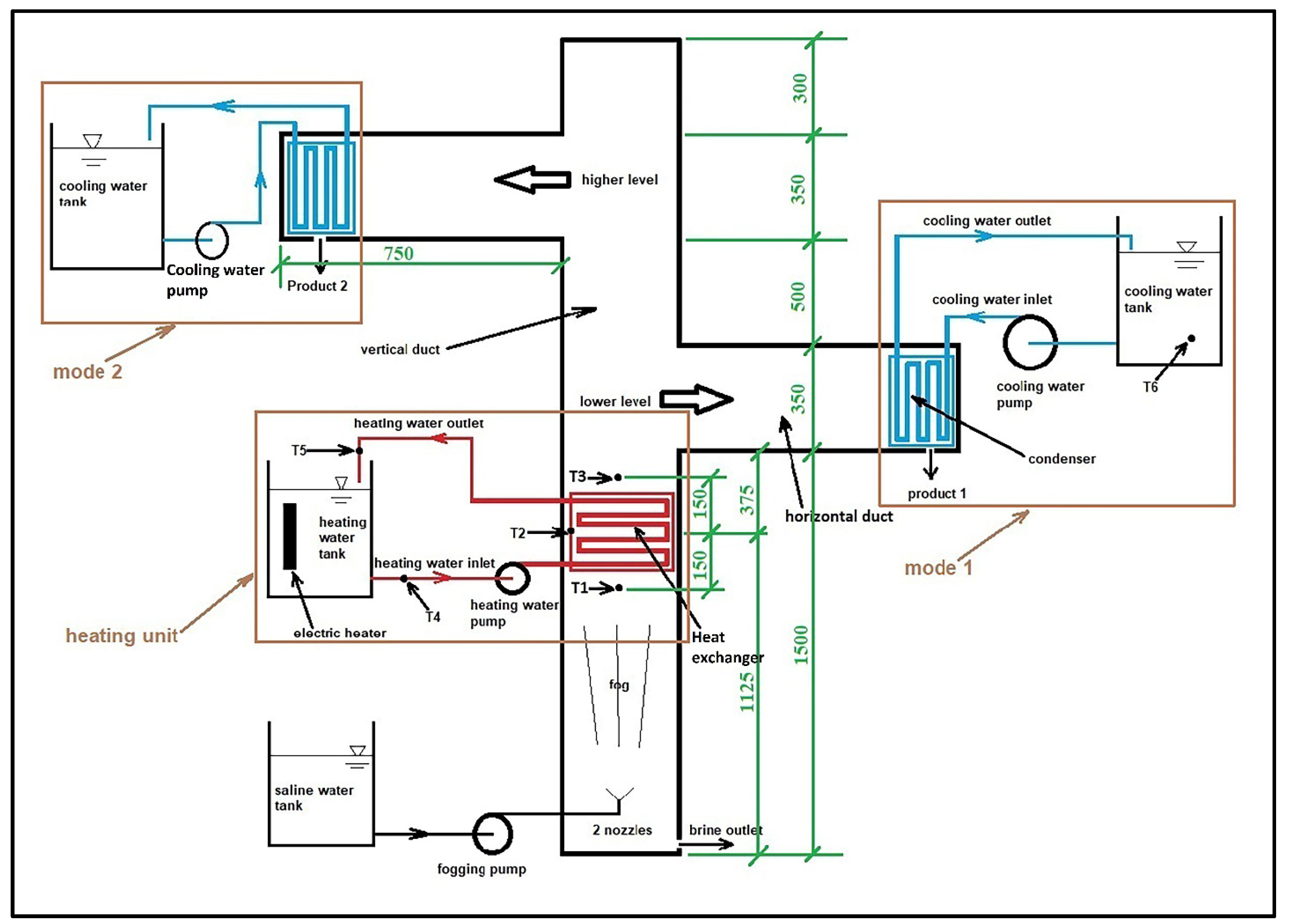
4.3. Spray Evaporator Desalination Systems

Chen et al. [38] used a spray evaporator at low temperatures (15–55 °C) to promote the evaporation process. This system was powered by a solar collector. Their system applied a coil condenser and feed tank as shown in Figure 20. The solar heater is used to heat the feed tank bypassing pure water in tubes. Heated saline water coming from the feed tank is sprayed into the evaporator. The vapor is released up to the coil, where it is condensed by brine water. Finally, condensate is collected and the brine is heated by the heat of condensation before going to the tank again. They investigated the performance of the system experimentally and theoretically. Moreover, they performed an exergy analysis to evaluate the energy losses in their system. The results showed that the losses of solar collector performance and spray evaporator were responsible for the inefficiency of the system. Additionally, the maximum productivity was 30 kg/d at a solar collector area of 7.6 m2 and a storage tank of size 305 kg under Singapore’s climatic conditions. They also presented an optimized design capable of running in the long term.
Ikegami et al. [39] studied experimentally the process of spray flash process using an upward spray. They carried out a comparison with the downward spray direction of previous works [40] under the same conditions. Their system applied 20 mm internal diameter stainless steel cylindrical steel sprayers with a length of 81.3 mm.
Heated saline water at 24.0, 30.0 and 40.0 °C with inlet velocity ranging from 1.74 to 3.62 m/s was injected into a high-pressure chamber. It was observed that the upward flash evaporation completed shorter than the downward flash one as the mean velocity of the spraying increased under the same inlet temperature of 24.0 °C. For the upward flash evaporation at a spray temperature of 30 °C, the evaporation was completed at a short vertical distance and lower velocity. They concluded that the higher the inlet temperature was, the higher promoted flash evaporator was. Further, the empirical equation for the downward spray direction is not valid for the upward one. For the downward spray, lowering the mean velocity of the spraying boosted the evaporation process in contrast to the evaporation process in the case of the upward spray.
Chen et al. [41] investigated theoretically the spray evaporation process based on the droplets analysis. A mathematical model was developed and compared to previous work. Their system used a nozzle with a diameter of 5 mm, which was directed vertically downward as shown in Figure 21. Heated saline water is injected into the 5 mm nozzle, which is directed vertically downwards. As a result, the vapor is collected by passing through the demister and then to the condenser which is run by a cold saline water stream. The results showed that the capability of the compact design of spray evaporators could be achieved by producing smaller droplets, which in turn, promotes the evaporation rate. The complete evaporation of the droplets can be achieved at a height of 900 mm downward with droplet diameters of 500 µm. Moreover, increasing the initial velocity of the droplets decreased the thermal efficiency in contrast to the productivity, which increased due to the increase in the mass flow rate.
Hamed et al. [42] experimentally and theoretically investigated a solar-powered humidification–dehumidification desalination system integrated with an evacuated tube solar water heater as shown in Figure 22. Firstly, saline water is pumped from a saline water tank to the dehumidifier section for preheating before entering the solar collector. Heated saline water is sprayed in the humidifier section by a circulation pump. Air is forced circulated at a closed loop. Temperature is measured at various locations in the system using thermocouples connected to a temperature recorder integrated with a computer. They tested their system in two sets of experiments. The first was from 9 AM to 5 PM, whereas the second was from 1 AM to 5 PM after preheating the saline water. The results showed that the 4 h operating system has higher performance with 22 kg/d compared to the 8 h operating system with 16 kg/d. Moreover, productivity increased by raising saline water temperatures at the humidifier inlet. There was a good agreement between experimental and theoretical work. Finally, it was reported that the cost was 0.0578 USD/kg.
Prakash Narayan et al. [43] reviewed previous techniques related to HDH and presented a theoretical study to improve or optimize the HDH desalination technique. They reached high system performance by multi-extraction, multi-pressure and thermal vapor compression cycles. They reached better performance other than conventional systems. The best performance was 5 (GOR). Prakash Narayan et al. [44] discussed various small-scale solar HDH desalination systems in terms of the limitations, classifications and components of solar HDH desalination cycles. They also presented some other alternative similar HDH cycles. In the last paragraphs, they outlined some improvements for HDH cycles. Mistry et al. [45] tried to investigate the performance of thermal desalination systems in terms of second-law efficiency. They defined the second law as the minimum required power to separate water from the salt of a unit of saline water. They applied mathematical models to estimate the amount of entropy generation throughout the cycle components and processes. The main advantage of their models was their ability to estimate the entropy generation for different desalination techniques such as MED, MFD, MD, RO, HDH, and vapor compression cycles. Additionally, they recommended considering chemical and physical exergy when calculating the exergy. The obvious difference between the exergy efficiency and the second law efficiency is that the former compares the possible efficiencies with respect to the ambient conditions, in other words, the dead state while the latter considers the operating conditions when efficiencies are being calculated. As shown in Figure 23, ELzayed et al. [46] tried to enhance the performance of the HDH desalination system by reaching a thermodynamic balance between different streams in different processes. They presented their data in a temperature enthalpy diagram and defined some parameters such as dimensionless enthalpy pinch to measure the degree of thermal efficiency. Additionally, they did an economic analysis to observe the feasibility of this method to reduce the cost of production. The results indicated that this model can reduce the cost by 40%. The outputs also showed that the dehumidifier is the key factor more than the humidifier in determining GOR.
Table 1. Summary of HDH desalination systems.
No.ReferenceYearSetupHumidifierDehumidifierProductivityPerformanceCost
1Sharshir et al. [21]2016Hybrid desalination system of an HDH unit integrated with four solar stillsPacking material cellulose typeCopper coil with corrugated fins66.3 kg/d(GOR) 3.180.034 USD/kg
2Zubair et al. [22]2017Solar HDH desalination (evacuated tube solar water heater)--2.2197 kg/h(GOR) 1.850.032 USD/kg
3Nematollahi et al. [23]2013Solar HDH desalination systemCylindrical galvanized iron tube filled with Pall RingsA galvanized shell-and-tube heat exchanger0.17 kg/m2·h--
4Amer et al. [24]2009Conventional HDH desalination system (CAOW)Packed bed
((gunny bag cloth), (plywood slates) and (PVC
sheets))
The dimensions of the condensation tower are 200 cm in height, 40 cm in length, and 50 cm in width. A copper tube formed as a coil is used as a condenser of 15 m in length and 1.27 cm outer diameter.5.8 L/h--
5Zhani and Ben Bacha [25]2010Solar HDH desalination systemTextile (viscose) surface is used as packing to increase the interface area between
the air and water, which form the wetted surface
Dismantled copper vertical rows, to ensure their maintenance, and organized in a triangular arrangementMaximum
(21.7 kg/day)
-1.6 €/day
6Yuan and Zhang [26]200724 h/d operating HDH desalination systemClosed tower structure tank driven by blowers-5.2 kg/m2/d--
7Al-Hallaj et al. [27]1998Conventional solar HDH desalination systemCooling tower
built of wooden structure and fixed in the second
duct
Galvanized steel plates. A copper tube was welded to
the dehumidifier plate in a helical shape
Peak hourly productivity 0.7 kg/m2·hPerformance factor = 1.8
8Yamali and Solmus [28]2008A double-pass flat-plate solar
air heater HDH desalination system.
Four pads in series, made of plastic material
and it forms the wetted surface of the humidifier
Three-air cooler heat exchangers
manufactured with copper tubes and corrugated
aluminium fins
2.5 kg/h--
9Orfi et al. [29]2004Solar HDH desalination systemFive parallel plates made of wood and
covered with textile (cotton) are fixed
Two rows of
long cylinders made of copper
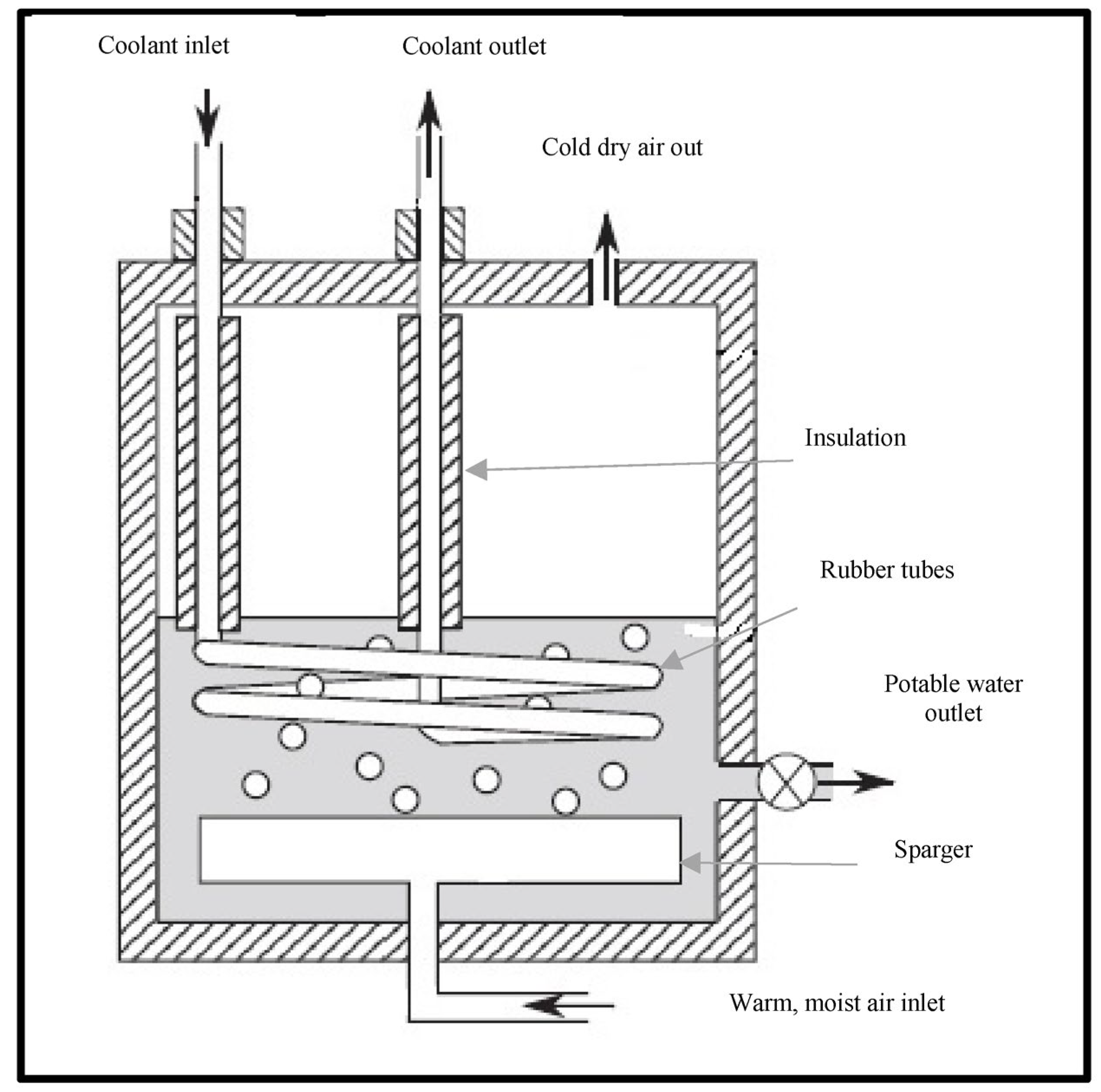
---
10El-Agouz [30]2010HDH desalination system (air through seawater)Bubble-column humidifierA two-shell and tube heat exchanger8.22 kg/hEfficiency ~80%0.046 USD/kg
11Tow and Lienhard [31]2014Direct-contact
dehumidification in bubble columns
-Direct-contact
dehumidification in bubble columns
-Dehumidifier effectiveness peaked at nearly 0.99-
12Muthusamy and Srithar [32]2015HDH desalination system using various insertsMade of polyvinyl
chloride (PVC) tube of 152 mm diameter and 800 mm height; packing
materials are arranged in two layers
Shell and
tube condenser with one shell and 5 tube passes
0.340 kg/h44% energy efficiency;
38% exergy efficiency
-
13Srithar and Rajaseenisaan [33]2017Solar HDH desalinationSingle-basin single-slope solar still with the provision for the air inlet and outletThe glass covering the solar still20.61 kg/m2·d--
14Li et al. [34]2014Solar HDH desalination (solar air heater with evacuated tubes)One cassette made of corrugated cellulosic material, which constitutes the large and wetted
surface
A chamber with a rectangular cross-section; two rows of long tubes made of copper1000 L/day--
15Yamali and Solmus [35]2007Solar HDH desalination system (double-pass flat plate solar air heater)--10 kg/day--
16Guofeng et al. [36]2011Solar HDH desalination system (air and water solar heaters)Covered with polyurethane sandwich panels, of which the upper and lower boards
were pre-painted stainless steel sheets
Fin-tube heat exchanger with no insulation between the humidifier section1000 L/day-19.2 Yuan/m3
17Zhani [37]2013Mathematical model of solar HDH desalination systemPacked bed “horn trees or palm tree leaves”The condensation chamber contains polypropylene condensation plates~2.25 kg/h(GOR) ~ 3.0-
18Narayan et al. [43]2009Theoretical improvement of HDH desalination systems---(GOR) ~ 5.0-
19Prakash Narayan et al. [44]2010Review paper with novel proposals for improvement
20Mistry et al. [45]2011Investigate the performance of HDH in terms of second-law efficiencyPresent physical models that could be applied to different thermal desalination systems
21ELzayed et al. [46]2020Enhance the performance of HDH by reaching thermodynamics balancing in different components1.7 m height structured packing humidifier with a square cross-sectional area of 30 × 30 cm2 made of galvanized mild steel sheets of 1 mm thicknessFin-tube copper coils through which water partially gains heat indirectly from moist air. The copper coils have a square dimension of 30 cm × 30 cm and the coil diameter is ¼ inches11.5 L/h(GOR) ~ 0.99reduce the cost by 40%
(0.033 USD/L.)
22Lienhard [47]2019Book chapter discussed some problems such as energy consumption and the effectiveness of different processes
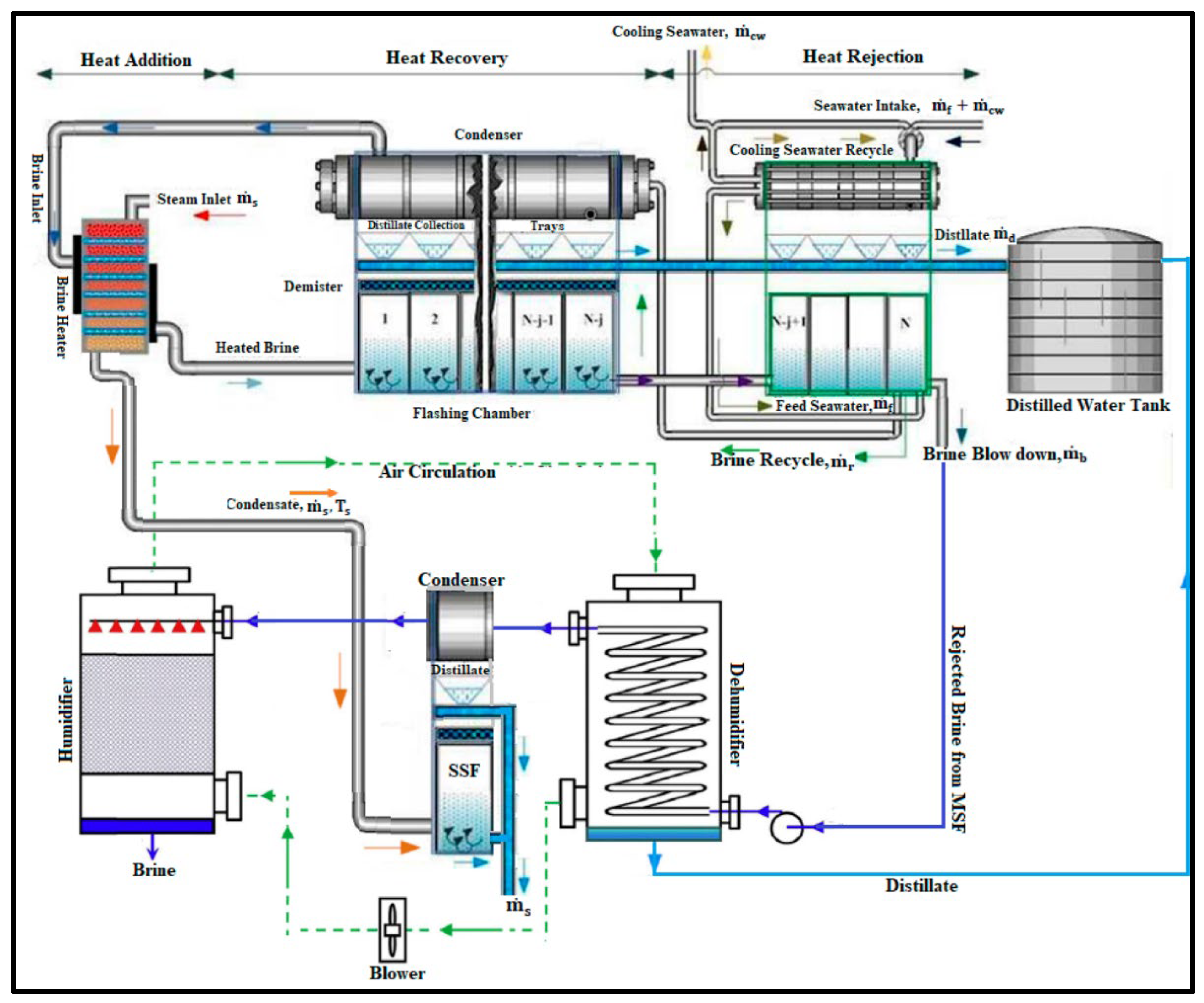
23Lawal et al. [48]2021A hybrid system of MSF and HDH desalination system--5 L/h(GOR) ~ 8.731.068 USD/m3
24Soomro et al. [49]2021Solar HDH desalination system powered by air–water solar heater--6.2 kg/h(GOR) ~ 3.35-
Lienhard [47] discussed various types of HDH desalination cycles and handled some crucial issues such as energy consumption and the effectiveness through different processes, and the amount of mass extracted and injected to enhance system performance. He also discussed the idea of a bubble-column dehumidifier. As shown in Figure 24, Lawal et al. [48] enhanced both the performance and productivity of a MSF system by integration with HDH. Their main idea was to recover energy from the MSF system. They used the cooling water from the condenser to provide the humidifier with the required hot water. Their hybrid system achieved 8.73 (GOR) and the cost was 1.068 USD/m3. As shown in Figure 25, Soomro et al. [49] investigated the performance of a solar HDH desalination system. The main difference in this study is that they preheated both air and water using one solar heater to increase the performance of the system. The maximum hourly productivity was 6.2 kg and the maximum GOR was 3.35 for June.

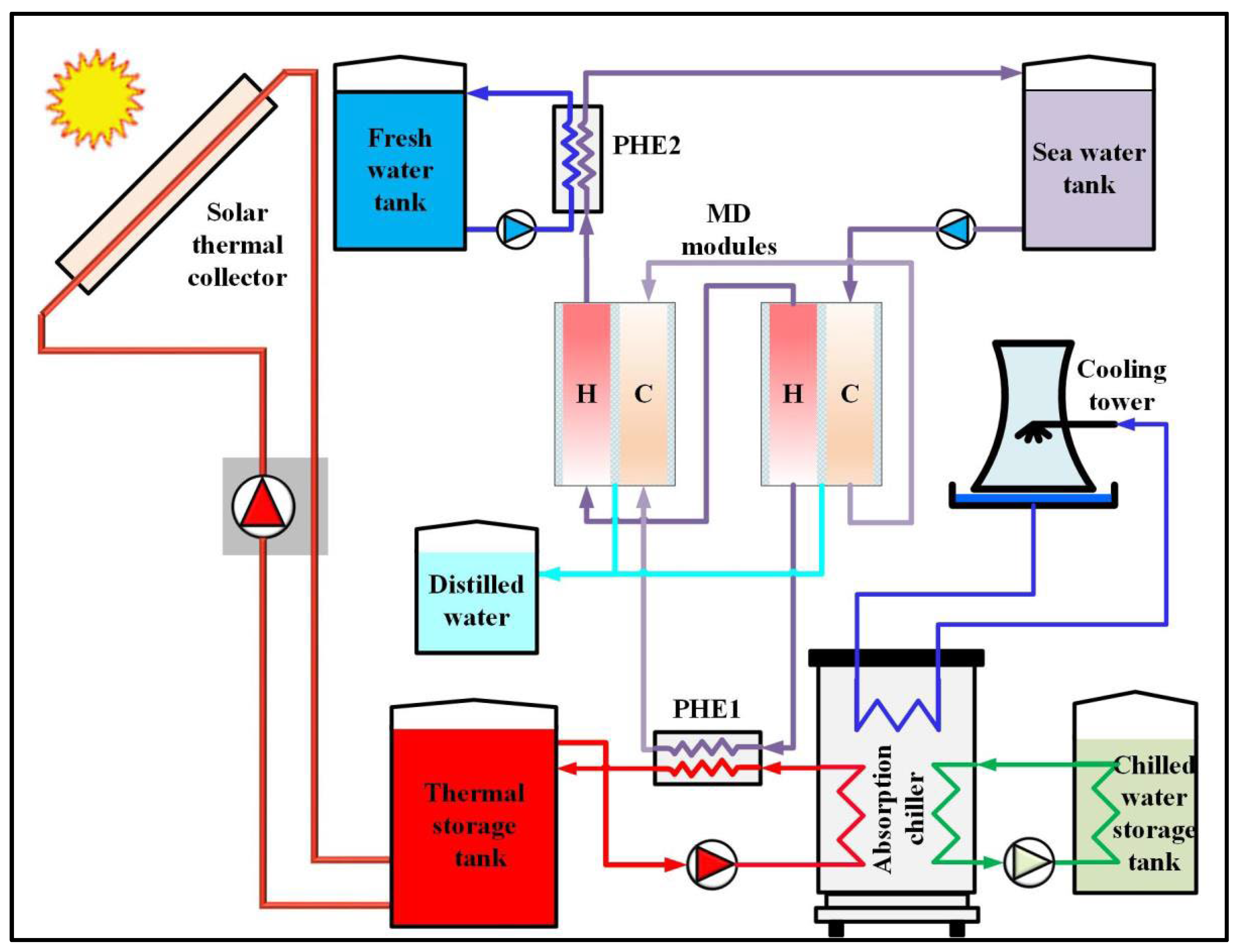
5. Recent Solar Membrane Desalination Systems

MD is another thermal distillation method. A membrane with a given porosity is used to separate the water vapor from salt. The main idea is that the porous material allows the vapor to pass into the other side, leaving the saline water on one side [50,51]. Much research has discussed hybrid solar-powered membrane desalination systems to enhance the overall system performance by recovering energy from the MD. Mohan et al. [52] examined a novel hybrid desalination system using various types of solar heaters under a United Arab Emirates climate. Their system contains a MD unit, an absorption refrigeration unit and solar heater modules as indicated in Figure 26 [53]. Their study tried to optimize the system performance by investigating the solar area and slope of the solar heater, water mass flow rates, and storing capacity. The project lifetime is 520,000 USD with 6.75 years lowest recovery period. The maximum cooling load was 35 kW and the maximum yield was 80 L/h per year.
Byrne et al. [54] established a mathematical model of a membrane distillation heat pump for a desalination cooling design to calculate the resulting potable water as a function of the cooling load. The results indicated that the studied configuration offers better perspectives than the RO system under the same produced water and the same cooling capacity. Ghaffour et al. [55] studied a hybrid membrane cooling adsorption distillation system powered by solar, geothermal or waste energy. The outputs indicated that the specific energy consumption of the proposed system is less than 1.5 kWh/m3 with 8 m3. Shafieian et al. [56] introduced the heat from exhaust fumes and cooling marine engines to supply heat for the MD absorption system. Ayou et al. [57] theoretically examined the exergy and energy of MD absorption design run by solar and biomass energy. The total water produced is 41.4 m3/day. The cooling capacity is 130 kW. The findings from the majority of previous research indicated that hybrid systems are an excellent way to enhance the performance of the system and effectively reduce costs.

6. Recent Direct Solar Desalination Systems

In their review paper, Ahmed et al. [58] presented a future look of solar-powered desalination systems. Later, Abu EL-Maaty et al. [59,60] investigated the fogging technique in solar-powered desalination processes as shown in Figure 27 as follows. Hot water is misted and sprayed upwards by a fog pump. This pump is reciprocated and selected to produce a high-pressure mist through a very small-orifice nozzle. A vertical fine mist stream is promoted. Depending on the experimental findings, the fog was able to overcome gravity and is released upwards to high levels. The condensation process at different upper heights indicated that this method is capable of distilling saline water. Since the ultimate goal is to produce potable water at high rates, a heat exchanger is fixed in the track of the mist to stimulate the evaporation of the droplets which are not fully evaporated. Additionally, introducing a heat exchanger creates a high-temperature difference between the heat exchanger and the condenser, so the air that existed inside the duct is heated and humidified on one a lower level and cooled and de-humified at a higher level, enabling a natural circulation process. Finally, this method applies three effects—very small saline droplets, heating the mist track, and the natural circulation of air.
The setup was designed at Mansoura University, Egypt. The mechanism involves two sections: the fog process section and the solar heater (ETSWH). Figure 28 shows the schematic diagram of the system. Hot saline water from the solar heater (7) is injected using a 60 W fog pump (1) through two fog nozzles. These nozzles have orifices of 100 µm. Fog nozzles are directed vertically and fixed in a square tank (2) with a length of 0.33 m and a height of 0.76 m. Above this tank, a transparent square duct is placed with a length of 0.33 m and a height of 1.07 m (3). This duct aims to make the flow visible. A solar-powered heater of the finned tube type (4) is placed in this transparent duct at a distance of 0.33 m above the lower edge of this duct. The heater surface also functions as a tool for reducing the fog salinity by preventing the high-density droplets from flowing up with the lower-density stream. As a result, both air and fog are heated before rising to the horizontal duct (5) of 0.33 m depth and 0.95 m length connected to a condenser (6) powered by a cooling cycle (9). At this point, the water vapor carried by air is condensed. It should be noted that the hot saline water is firstly circulated by a circulation pump (8) into the heater (4) before entering the high-pressure fog pump (40 bars). This pump works intermittently due to overheating. Figure 29 shows the photo of the used system.
Alhindawi et al. [61] experimentally studied fog desalination effectiveness with both water temperature, degree of water salinity and duct elevation. They established two different system configurations to collect water vapor at different heights as shown in Figure 30. They found that this technique is capable to reduce the salinity from 30,000 ppm to 2874 ppm at an inlet water temperature of 90 °C. Additionally, the effectiveness reached 92.94%. They also highlighted some recommendations for future stages depending on their experimental findings.
In the literature, some other reports focusing on interfacial solar steam generation systems in recent years exist. For example, Shi et al. [62] established a hydrogel membrane with a high surface area to produce fresh water. At night, this membrane can absorb fog droplets efficiently and combine them into a container, through daytime, it works as an interfacial solar steam generator as shown in Figure 31. The results indicated that the yield during the daytime reached 3.64 kg/m2·h using 1 sun. The outdoor test demonstrated that the total production of this membrane could reach 34 L/m2.
Zhang et al. [63] applied two types of naturally occurring molecules to establish low-cost and highly efficient solar evaporators as shown in Figure 32. They developed their system 3D printed with conical arrays to enhance the light-harvesting intensity. The peak yield reached 1.96 kg/m2·h under one sun.
Bai et al. [64] used waste plastics to treat wastewater. They presented a facile solvothermal technique to produce a large amount of Co-MOF nanorods from certain types of waste bottles as shown in Figure 33 and Figure 34. They aimed to purify wastewater as well as produce fresh water using Co-MOF nanotubes. Their results showed these tubes have low heat conductance, high absorption of solar heat and super-hydrophilicity. The evaporation rate reached 2.25 kg/m2·h using 1 kW/m2. The main contribution of this research was not merely recycling waste plastics but also establishing a feasible way to purify wastewater.

7. Future Recommandations

Enhancing the performance of solar desalination techniques represents a good way towards good exploitation of energy resources and although much research has been performed in this regard, many efforts are still needed in new innovative techniques. For example, the fog desalination technique represents a promising technique that may provide more water production in the future. Therefore, much research is still necessary for this technique as few attempts aim to prove this concept. More experimental investigations are needed on the system designs, fog nozzle diameters, direction of spraying, spots of heating within the system, type of the fog pump used, overheating problems of the fog pumps and operating and weather conditions.

8. Conclusions

In conclusion, solar desalination systems have gained significant attention as a promising solution to the global water scarcity problem. With the increasing focus on desalination research, many innovative methods are being developed to extract salts from saline water. The use of renewable energy, particularly solar energy, is considered a viable alternative to fossil fuel energy for desalination. This review has focused on direct and indirect solar desalination methods, specifically traditional direct solar desalination methods such as solar still and humidification dehumidification (HDH) desalination systems. This review has highlighted recent advancements in solar stills, such as the use of wicks to increase productivity and stepped solar stills. It has also briefly discussed the fogging process and the development of the HDH desalination system. This review has shown that solar desalination is a promising and sustainable solution to the water scarcity problem, and ongoing research and development will further enhance the efficiency and effectiveness of these systems.

Funding

This research received no external funding.

Data Availability Statement

Not applicable.

Acknowledgments

This paper is based upon work supported by the Faculty of Engineering, Mansoura University, Mansoura, Egypt.

Conflicts of Interest

The authors declare no conflict of interest.

Abbreviations

CAOWClosed-air, open-water cycles
EDElectric dialysis
ETSWHEvacuated tube solar water heater
GORGained output ratio
HDHHumidification dehumidification
MDMembrane desalination
MEDMulti-effect desalination
MEEMulti-effect evaporation
MOFMetal-organic frame
MSFMulti-stage flash desalination
MVCMechanical vapor compressor
OACWOpen-air, closed-water cycles
OAOWOpen-air, open-water cycles
PCMPhase change material
PVPhotovoltaic
ROReverse osmosis
TVCThermal vapor compression
UNICEFUnited Nations Children’s Fund

References

  1. Engelman, R. People in the Balance; Population Action International: Washington, DC, USA, 2000; Available online: https://www.populationaction.org (accessed on 19 March 2023).
  2. Vigotti, R.; Hoffman, A. Workshop on Renewable Energy and Water. IEA Working Party on Renewable Energy Technologies. 2009. Available online: https://www.un.org/waterforlifedecade/scarcity.shtml (accessed on 19 March 2023).
  3. WWAP. The United Nations World Water Development Report 2018; Nature-Based Solutions, UNESCO: Paris, France, 2018. [Google Scholar]
  4. Liburd, S. Solar-Driven Humidification-Dehumidification Desalination for Potable Use in Haiti. Available online: https://dspace.mit.edu/handle/1721.1/62033 (accessed on 30 June 2018).
  5. Multiple Ways of Assessing Threats to Water: Supply-Side and Demand-Side Problems. Available online: https://www.fewresources.org/water-scarcity-issues-were-running-out-of-water.html (accessed on 19 March 2023).
  6. Government of Canada. Available online: https://www.canada.ca/en/environment-climate-change/services/environmental-indicators/residential-water-use.html (accessed on 19 March 2023).
  7. Rajagopal, R.; Wichman, M.; Brands, E. Ency Pp—Water Drinking—IEG; Wiley & Sons: Hoboken, NJ, USA, 2017. [Google Scholar] [CrossRef]
  8. University of Oxford, Our World in Data. Available online: https://ourworldindata.org/water-use-stress (accessed on 19 March 2023).
  9. Ullah, I.; Rasul, M.G. Recent Developments in Solar Thermal Desalination Technologies: A Review. Energies 2019, 12, 119. [Google Scholar] [CrossRef]
  10. Chopra, K.; Tyagi, V.V.; Pandey, A.K.; Sari, A. Global advancement on experimental and thermal analysis of evacuated tube collector with and without heat pipe systems and possible applications. Appl. Energy 2018, 228, 351–389. [Google Scholar] [CrossRef]
  11. Miller, J.E. Review of Water Resources and Desalination Technologies; Release Report SAND-2003-0800; Sandia National Laboratories Unlimited: Livermore, CA, USA, 2003.
  12. Burn, S.; Hoang, M.; Zarzo, D.; Olewniak, F.; Campos, E.; Bolto, B.; Barron, O. Desalination techniques—A review of the opportunities for desalination in agriculture. Desalination 2015, 364, 2–16. [Google Scholar] [CrossRef]
  13. Alaian, W.M.; Elnegiry, E.A.; Hamed, A.M. Experimental investigation on the performance of solar still augmented with pin-finned wick. Desalination 2016, 379, 10–15. [Google Scholar] [CrossRef]
  14. Rajaseenivasan, T.; Tinnokesh, A.P.; Rajesh Kumar, G.; Srithar, K. Glass basin solar still with integrated preheated water supply–Theoretical and experimental investigation. Desalination 2016, 398, 214–221. [Google Scholar] [CrossRef]
  15. Kabeel, A.E.; Khalil, A.; Omara, Z.M.; Younes, M.M. Theoretical and experimental parametric study of modified stepped solar still. Desalination 2012, 289, 12–20. [Google Scholar] [CrossRef]
  16. Kabeel, A.E.; Abdelgaied, M. Improving the performance of solar still by using PCM as a thermal storage medium under Egyptian conditions. Desalination 2016, 383, 22–28. [Google Scholar] [CrossRef]
  17. Hansen, R.S.; Narayanan, C.S.; Murugavel, K.K. Performance analysis on inclined solar still with different new wick materials and wire mesh. Desalination 2015, 358, 1–8. [Google Scholar] [CrossRef]
  18. Anburaja, P.; Hansenb, R.S.; Murugavela, K.K. Performance of an Inclined Solar Still with Rectangular Grooves and Ridges. Appl. Sol. Energy 2013, 49, 22–26. [Google Scholar] [CrossRef]
  19. El-Sebaii, A.A.; El-Naggar, M. Year round performance and cost analysis of a finned single basin solar still. Appl. Therm. Eng. 2017, 110, 787–794. [Google Scholar] [CrossRef]
  20. Parekh, S.; Farid, M.M.; Selman, J.R.; Al-Hallaj, S. Solar desalination with a humidification-dehumidification technique—A comprehensive technical review. Desalination 2004, 160, 167–186. [Google Scholar] [CrossRef]
  21. Sharshir, S.W.; Peng, G.; Yang, N.; Eltawil, M.A.; Ali, M.K.A.; Kabeel, A.E. A hybrid desalination system using humidification-dehumidification and solar stills integrated with evacuated solar water heater. Energy Convers. Manag. 2016, 124, 287–296. [Google Scholar] [CrossRef]
  22. Zubair, M.I.; Al-Sulaiman, F.A.; Antar, M.A.; Al-Dini, S.A.; Ibrahim, N.I. Performance and cost assessment of solar driven humidification-dehumidification desalination system. Energy Convers. Manag. 2017, 132, 28–39. [Google Scholar] [CrossRef]
  23. Nematollahi, F.; Rahimi, A.; Gheinani, T.T. Experimental and theoretical energy and exergy analysis for a solar desalination system. Desalination 2013, 317, 23–31. [Google Scholar] [CrossRef]
  24. Amer, E.H.; Kotb, H.; Mostafa, G.H.; El-Ghalban, A.R. Theoretical and experimental investigation of humidification-dehumidification desalination unit. Desalination 2009, 249, 949–959. [Google Scholar] [CrossRef]
  25. Zhani, K.; Ben Bacha, H. Experimental investigation of a new solar desalination prototype using the humidification-dehumidification principle. Renew. Energy 2010, 35, 2610–2617. [Google Scholar] [CrossRef]
  26. Yuan, G.; Zhang, H. Mathematical modelling of a closed circulation solar desalination unit with humidification-dehumidification. Desalination 2007, 205, 156–162. [Google Scholar] [CrossRef]
  27. Al-Hallaj, S.; Farid, M.M.; Tamimi, A.R. Solar desalination with a humidification- dehumidification cycle: Performance of the unit. Desalination 1998, 120, 273–280. [Google Scholar] [CrossRef]
  28. Yamali, C.; Solmus, I. A solar desalination system using humidification-dehumidification process: Experimental study and comparison with the theoretical results. Desalination 2008, 220, 538–551. [Google Scholar] [CrossRef]
  29. Orfi, J.; Laplante, M.; Marmouch, H.; Galanis, N.; Benhamou, B.; Ben Nasrallah, S.; Nguyen, C.T. Experimental and theoretical study of a humidification-dehumidification water desalination system using solar energy. Desalination 2004, 168, 151–159. [Google Scholar] [CrossRef]
  30. El-Agouz, S. A new process of desalination by air passing through seawater based on humidification-dehumidification process. Energy 2010, 35, 5108–5114. [Google Scholar] [CrossRef]
  31. Tow, E.W.; Lienhard, V.J.H. Experiments and modelling of bubble column dehumidifier performance. Int. J. Therm. Sci. 2014, 80, 65–75. [Google Scholar] [CrossRef]
  32. Muthusamy, C.; Srithar, K. Energy and exergy analysis for a humidification-dehumidification desalination system integrated with multiple inserts. Desalination 2015, 367, 49–59. [Google Scholar] [CrossRef]
  33. Srithar, K.; Rajaseenivasan, T. Performance analysis on a solar bubble column humidification-dehumidification desalination system. Process. Saf. Environ. Prot. 2017, 105, 41–50. [Google Scholar] [CrossRef]
  34. Li, X.; Yuan, G.; Wang, Z.; Li, H.; Xu, Z. Experimental study on a humidification-dehumidification desalination system of solar air heater with evacuated tubes. Desalination 2014, 351, 1–8. [Google Scholar] [CrossRef]
  35. Yamali, C.; Solmuş, I. Theoretical investigation of a humidification-dehumidification desalination system configured by a double-pass flat plate solar air heater. Desalination 2007, 205, 163–177. [Google Scholar] [CrossRef]
  36. Yuan, G.; Wang, Z.; Li, H.; Li, X. Experimental study of a solar desalination system based on humidification-dehumidification process. Desalination 2011, 277, 92–98. [Google Scholar] [CrossRef]
  37. Zhani, K. Solar desalination based on multiple effect humidification process: Thermal performance and experimental validation. Renew. Sustain. Energy Rev. 2013, 24, 406–417. [Google Scholar] [CrossRef]
  38. Chen, Q.; Ja, M.K.; Li, Y.; Chua, K.J. Evaluation of a solar-powered spray-assisted low-temperature desalination technology. Appl. Energy 2018, 211, 997–1008. [Google Scholar] [CrossRef]
  39. Ikegami, Y.; Sasaki, H.; Gouda, T.; Uehara, H. Experimental study on a spray flash desalination (influence of the direction of injection). Desalination 2006, 194, 81–89. [Google Scholar] [CrossRef]
  40. Miyara, A.; Uehara, H.; Hino, M. A study of the spray flash desalination (effect of number of nozzles). Bull. Soc. Sea Water Sci. Jpn. 1991, 45, 339–344. [Google Scholar]
  41. Chen, Q.; Thu, K.; Bui, T.D.; Li, Y.; Ng, K.C.; Chua, K.J. Development of a model for spray evaporation based on droplet analysis. Desalination 2016, 399, 69–77. [Google Scholar] [CrossRef]
  42. Hamed, M.H.; Kabeel, A.E.; Omara, Z.M.; Sharshir, S.W. Mathematical and experimental investigation of a solar humidification-dehumidification desalination unit. Desalination 2015, 358, 9–17. [Google Scholar] [CrossRef]
  43. Prakash Narayan, G.; Sharqawy, H.; Lienhard, H. Thermodynamic analysis of humidification dehumidification desalination cycles. Desalination Water Treat. 2010, 16, 339–353. [Google Scholar] [CrossRef]
  44. Prakash Narayan, G.; Sharqawy, H.; Summers, K.; Lienhard, H.; Zubair, M.; Antar, M.A. The potential of solar-driven humidification–dehumidification desalination for small-scale decentralized water production. Renew. Sustain. Energy Rev. 2010, 14, 1187–1201. [Google Scholar] [CrossRef]
  45. Mistry, H.; McGovern, K.; Thiel, P.; Summers, K.; Zubair, M.; Lienhard, H. Entropy Generation Analysis of Desalination Technologies. Entropy 2011, 13, 1829–1864. [Google Scholar] [CrossRef]
  46. Elzayed, S.; Ahmed, M.A.M.; Antar, A.; Sharqawy, H.; Zubair, M. The impact of thermodynamic balancing on the performance of a humidification dehumidification desalination system. Therm. Sci. Eng. Prog. 2021, 21, 100794. [Google Scholar] [CrossRef]
  47. Lienhard, J.H. Humidification-Dehumidification Desalination. In Desalination: Water from Water; Kucera, J., Ed.; Scrivener Publishing: Beverly, MA, USA, 2019; pp. 387–446. [Google Scholar]
  48. Lawal, D.U.; Antar, M.A.; Khalifa, A.E. Integration of a MSF Desalination System with a HDH System for Brine Recovery. Sustainability 2021, 13, 3506. [Google Scholar] [CrossRef]
  49. Soomro, S.H.; Santosh, R.; Bak, C.-U.; Kim, W.-S.; Kim, Y.-D. Humidification-Dehumidification Desalination System Powered by Simultaneous Air-Water Solar Heater. Sustainability 2021, 13, 13491. [Google Scholar] [CrossRef]
  50. Yadav, A.; Labhasetwar, P.K.; Shahi, V.K. Membrane Distillation Using Low-Grade Energy for Desalination: A Review. J. Environ. Chem. Eng. 2021, 9, 105818. [Google Scholar] [CrossRef]
  51. Ma, Q.; Xu, Z.; Wang, R. Distributed Solar Desalination by Membrane Distillation: Current Status and Future Perspectives. Water Res. 2021, 198, 117154. [Google Scholar] [CrossRef]
  52. Mohan, G.; Kumar, U.; Pokhrel, M.K.; Martin, A. A Novel Solar Thermal Polygeneration System for Sustainable Production of Cooling, CleanWater and Domestic HotWater in United Arab Emirates: Dynamic Simulation and Economic Evaluation. Appl. Energy 2016, 167, 173–188. [Google Scholar] [CrossRef]
  53. Alsaman, S.; Hassan, A.; Ali, S.; Mohammed, H.; Zohir, E.; Farid, M.; Zakaria Eraqi, M.; El-Ghetany, H.; Askalany, A. Hybrid Solar-Driven Desalination/Cooling Systems: Current Situation and Future Trend. Energies 2022, 15, 8099. [Google Scholar] [CrossRef]
  54. Byrne, P.; Ait Oumeziane, Y.; Serres, L.; Mare, T. Study of a Heat Pump for Simultaneous Cooling and Desalination. Appl. Mech. Mater. 2016, 819, 152–159. [Google Scholar] [CrossRef]
  55. Ghaffour, N.; Lattemann, S.; Missimer, T.; Ng, K.C.; Sinha, S.; Amy, G. Renewable Energy-Driven Innovative Energy-Efficient Desalination Technologies. Appl. Energy 2014, 136, 1155–1165. [Google Scholar] [CrossRef]
  56. Shafieian, A.; Khiadani, M. A Multipurpose Desalination, Cooling, and Air-Conditioning System Powered by Waste Heat Recovery from Diesel Exhaust Fumes and Cooling Water. Case Stud. Therm. Eng. 2020, 21, 100702. [Google Scholar] [CrossRef]
  57. Ayou, D.S.; Zaragoza, G.; Coronas, A. Small-Scale Renewable Polygeneration System for off-Grid Applications: Desalination, Power Generation and Space Cooling. Appl. Therm. Eng. 2021, 182, 116112. [Google Scholar] [CrossRef]
  58. Ahmed, F.E.; Hashaikeh, R.; Hilal, N. Solar powered desalination—Technology, energy and future outlook. Desalination 2019, 453, 54–76. [Google Scholar] [CrossRef]
  59. Abu El-Maaty, A.E.; Awad, M.M.; Sultan, G.I.; Hamed, A.M. Solar powered fog desalination system. Desalination 2019, 472, 114130. [Google Scholar] [CrossRef]
  60. Abu El-Maaty, A.E.; Awad, M.M.; Sultan, G.I.; Hamed, A.M. Performance study of fog desalination system coupled with evacuated tube solar collector. Desalination 2021, 504, 114960. [Google Scholar] [CrossRef]
  61. Alhindawi, A.A.; Elmarghany, M.R.; Hamed, A.M.; Abdelrehim, O. Effect of Saline-Fog Temperature and Collection-Duct Height on Fog-Desalination Effectiveness. Appl. Therm. Eng. 2023, 227, 120390. [Google Scholar] [CrossRef]
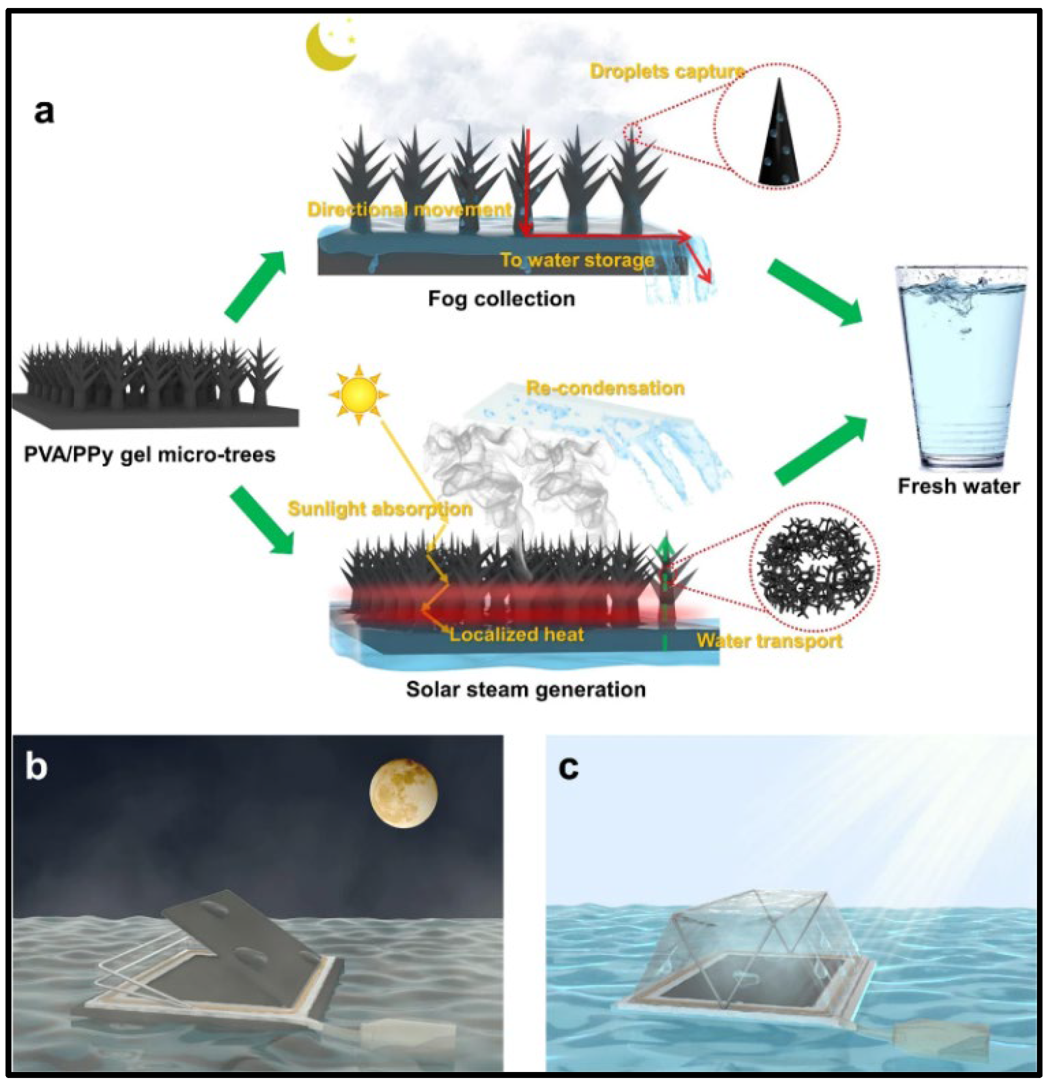
  62. Shi, Y.; Ilic, O.; Atwater, H.A.; Greer, J.R. All-day fresh water harvesting by microstructured hydrogel membranes. Nat. Commun. 2021, 12, 2797. [Google Scholar] [CrossRef] [PubMed]
  63. Zhang, X.; Yan, Y.; Li, N.; Yang, P.; Yang, Y.; Duan, G.; Wang, X.; Xu, Y.; Li, Y. A robust and 3D-printed solar evaporator based on naturally occurring molecules. Sci. Bull. 2023, 68, 203–213. [Google Scholar] [CrossRef] [PubMed]
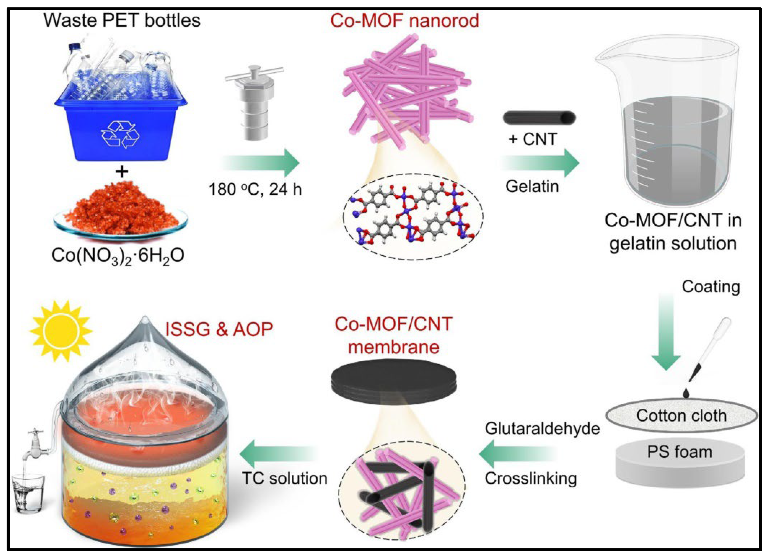
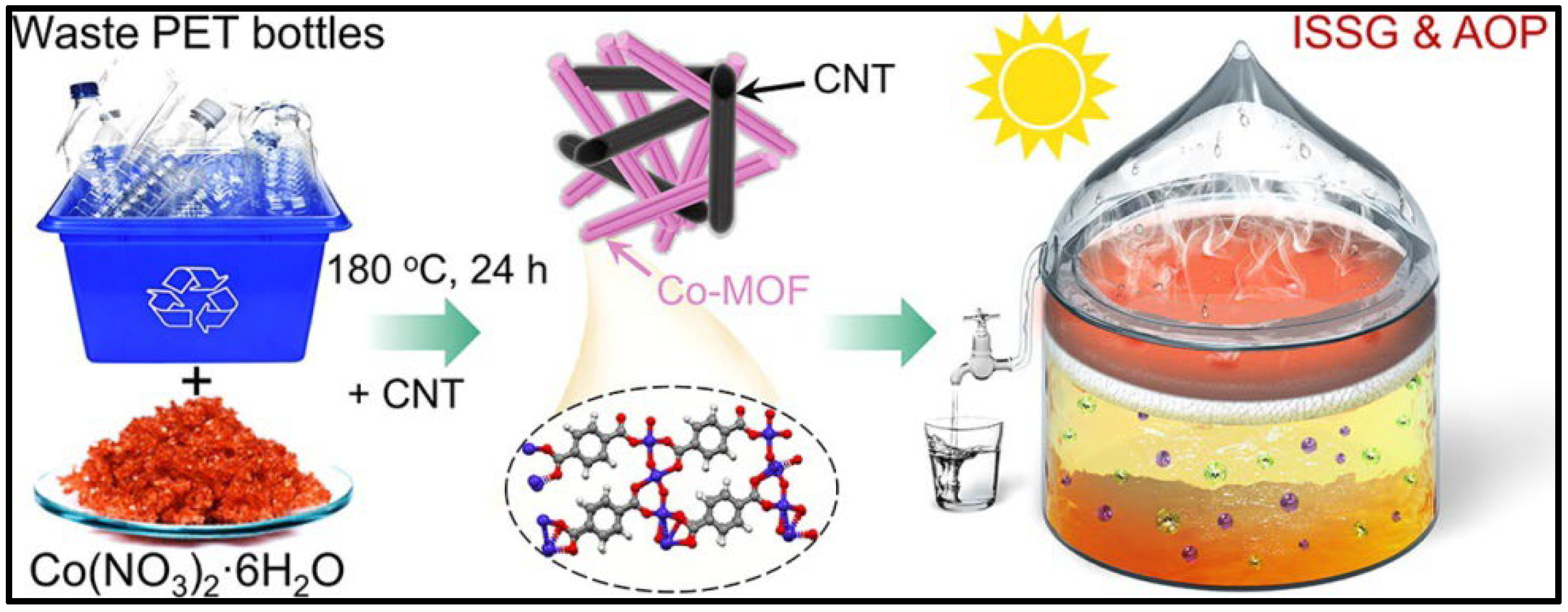
  64. Bai, H.; He, P.; Hao, L.; Fan, Z.; Niu, R.; Tang, T.; Gong, J. Waste-treating-waste: Upcycling discarded polyester into metal–organic framework nanorod for synergistic interfacial solar evaporation and sulfate-based advanced oxidation process. Chem. Eng. J. 2023, 456, 140994. [Google Scholar] [CrossRef]
Figure 1. Global potable water scarcity map in 2007 [4].
Energies 16 03957 g001
Figure 2. Worldwide potable water stress in 1995 and 2025 [3].
Energies 16 03957 g002
Figure 3. Daily use of potable water per person in different countries in 2010 [7].
Energies 16 03957 g003
Figure 4. Worldwide use of potable water in 2008 [8].
Energies 16 03957 g004
Figure 5. The performance of different desalination techniques.
Energies 16 03957 g005
Figure 6. Solar desalination methods.
Energies 16 03957 g006
Figure 7. The experimental test unit [13].
Energies 16 03957 g007
Figure 8. Solar still with preheater section [14].
Energies 16 03957 g008
Figure 9. Schematic diagram of the experimental device [15].
Energies 16 03957 g009
Figure 10. Schematic diagram of the experimental work [16].
Energies 16 03957 g010
Figure 11. Photographic view of the inclined solar still and the wick material [17].
Energies 16 03957 g011
Figure 12. Schematic diagram of the inclined solar still [18].
Energies 16 03957 g012
Figure 13. The finned basin solar still [19].
Energies 16 03957 g013
Figure 14. Experimental model of the hybrid desalination system [21].
Energies 16 03957 g014
Figure 15. System schematic diagram [24].
Energies 16 03957 g015
Figure 16. Solar HDH desalination system [25].
Energies 16 03957 g016
Figure 17. HDH desalination system with bubble-column dehumidifier [30].
Energies 16 03957 g017
Figure 18. Schematic diagram of the experimental dehumidifier [31].
Energies 16 03957 g018
Figure 19. Experimental setup of the system [34].
Energies 16 03957 g019
Figure 20. Experimental setup of the solar desalination system [38].
Energies 16 03957 g020
Figure 21. Schematic drawing of (a) the spray evaporator and (b) a single droplet [41].
Energies 16 03957 g021
Figure 22. Schematic drawing of the system [42].
Energies 16 03957 g022
Figure 23. Schematic drawing of the system [46].
Energies 16 03957 g023
Figure 24. Schematic drawing of the system [48].
Energies 16 03957 g024
Figure 25. Schematic drawing of the system [49].
Energies 16 03957 g025
Figure 26. Schematic drawing of the system [53].
Energies 16 03957 g026
Figure 27. The technique of fog desalination [59].
Energies 16 03957 g027
Figure 28. Schematic diagram of the solar-powered fog desalination system [60].
Energies 16 03957 g028
Figure 29. Photograph of the solar-powered fog desalination system [60].
Energies 16 03957 g029
Figure 30. Schematic diagram of the fog desalination setup [61].
Energies 16 03957 g030
Figure 31. All-day water harvesting device. (a) Physical demonstration of daytime and nighttime processes for water production (b) Nighttime mode (c) Daytime modes of the floating design [62].
Energies 16 03957 g031
Figure 32. The 3D-printed TAMA evaporator produces clean water [63].
Energies 16 03957 g032
Figure 33. Fabrication of a Co-MOF/CNT membrane [64].
Energies 16 03957 g033
Figure 34. Facile solvothermal technique [64].
Energies 16 03957 g034
Disclaimer/Publisher’s Note: The statements, opinions and data contained in all publications are solely those of the individual author(s) and contributor(s) and not of MDPI and/or the editor(s). MDPI and/or the editor(s) disclaim responsibility for any injury to people or property resulting from any ideas, methods, instructions or products referred to in the content.

