

Combined Analytic Hierarchy Process and Weighted Interval Method Models for the Geological Evaluation of CO2 Storage in Coal Goaf


Abstract
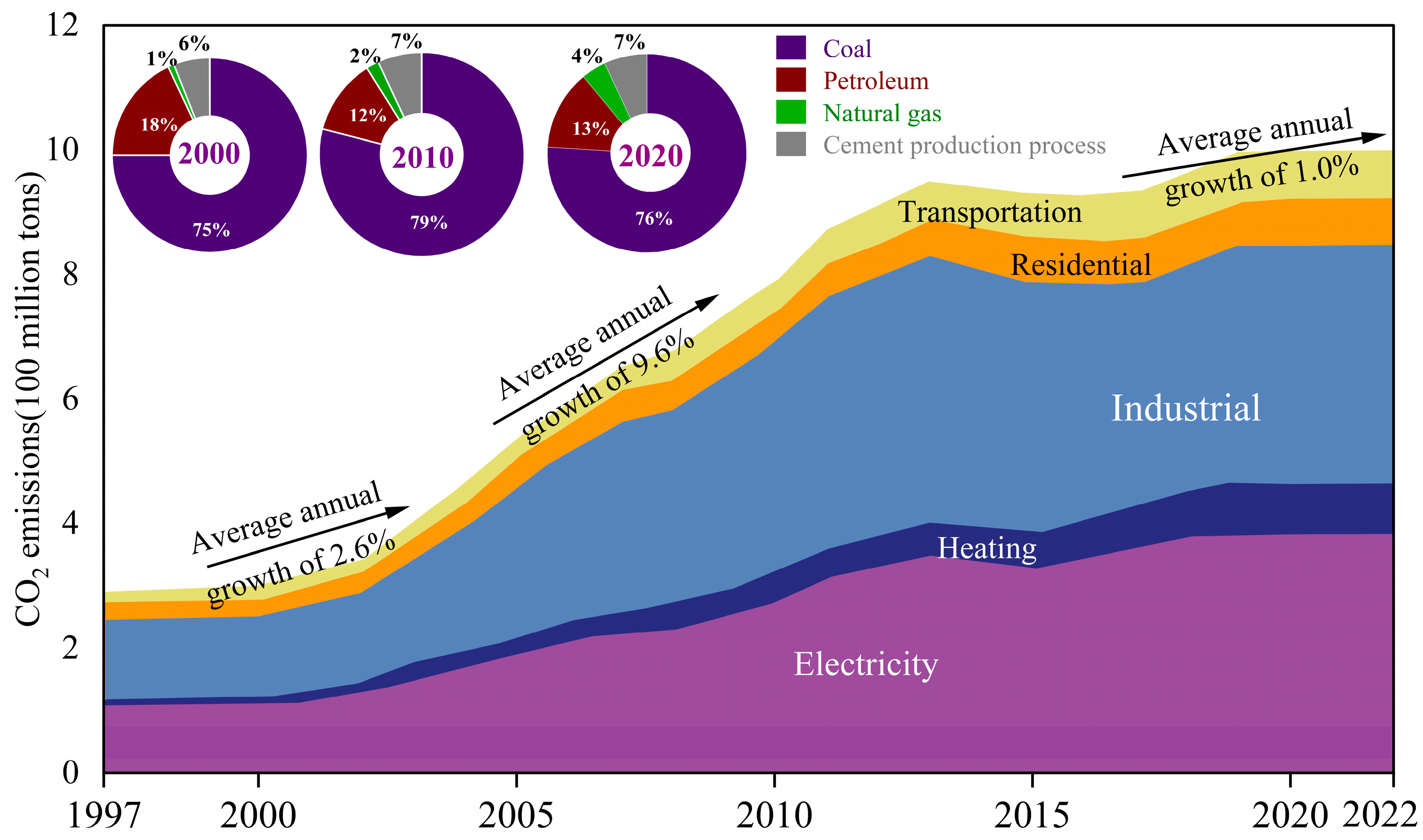
:1. Introduction
2. Methods and Materials
2.1. Methods of CO2 Geological Storage
2.2. Mechanism of CO2 Storage in Coal Goaf
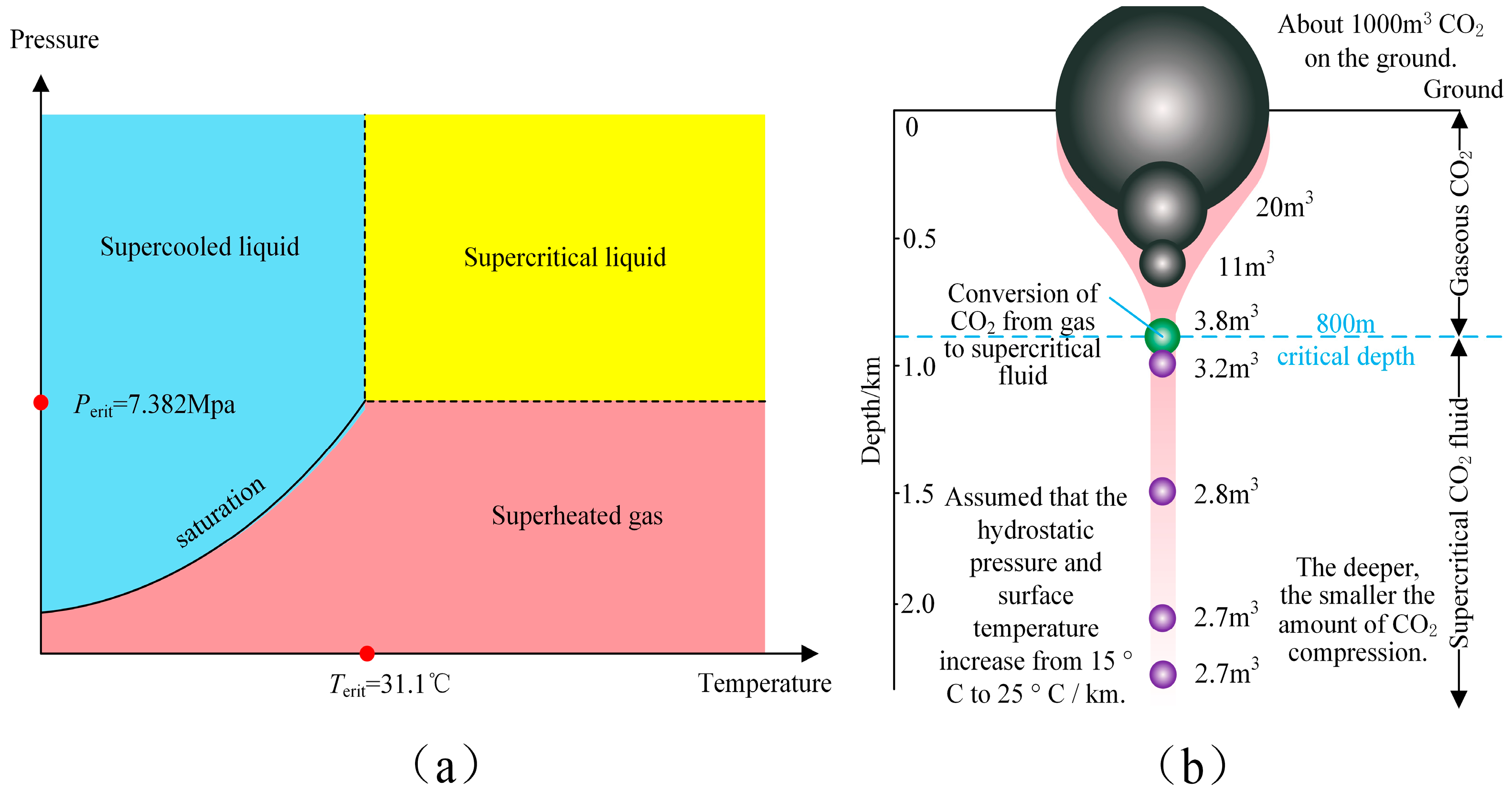
2.2.1. CO2 Physical Trapping
- (1)
- Geological trapping
- (2)
- Residual CO2 trapping
2.2.2. CO2 Chemical Trapping
- (1)
- Solubility trapping
- (2)
- Mineral trapping
2.3. Geological Evaluation Methods
2.3.1. Introduction to AHP and WIM Models
2.3.2. Methods of AHP and WIM Models
3. Results and Discussion
3.1. An Example of CO2 Geological Storage in Goaf
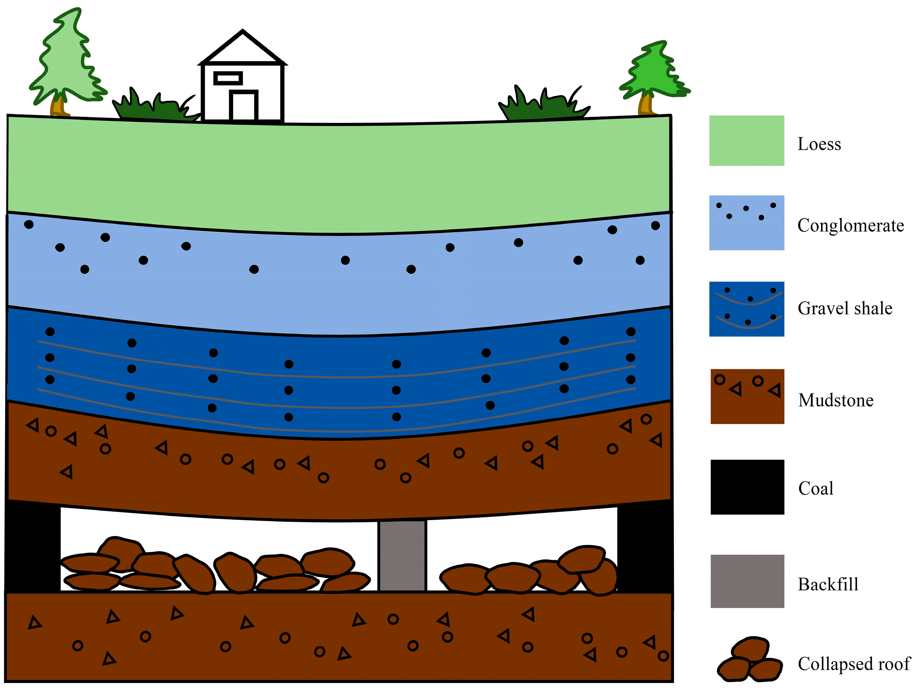
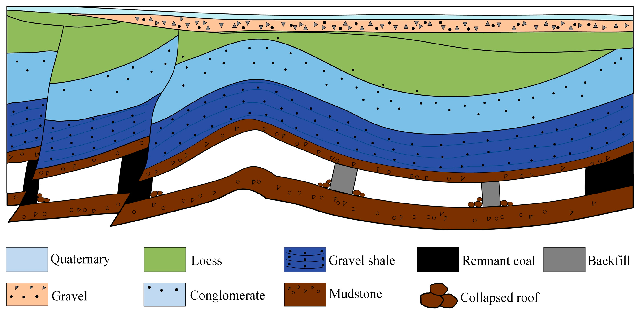
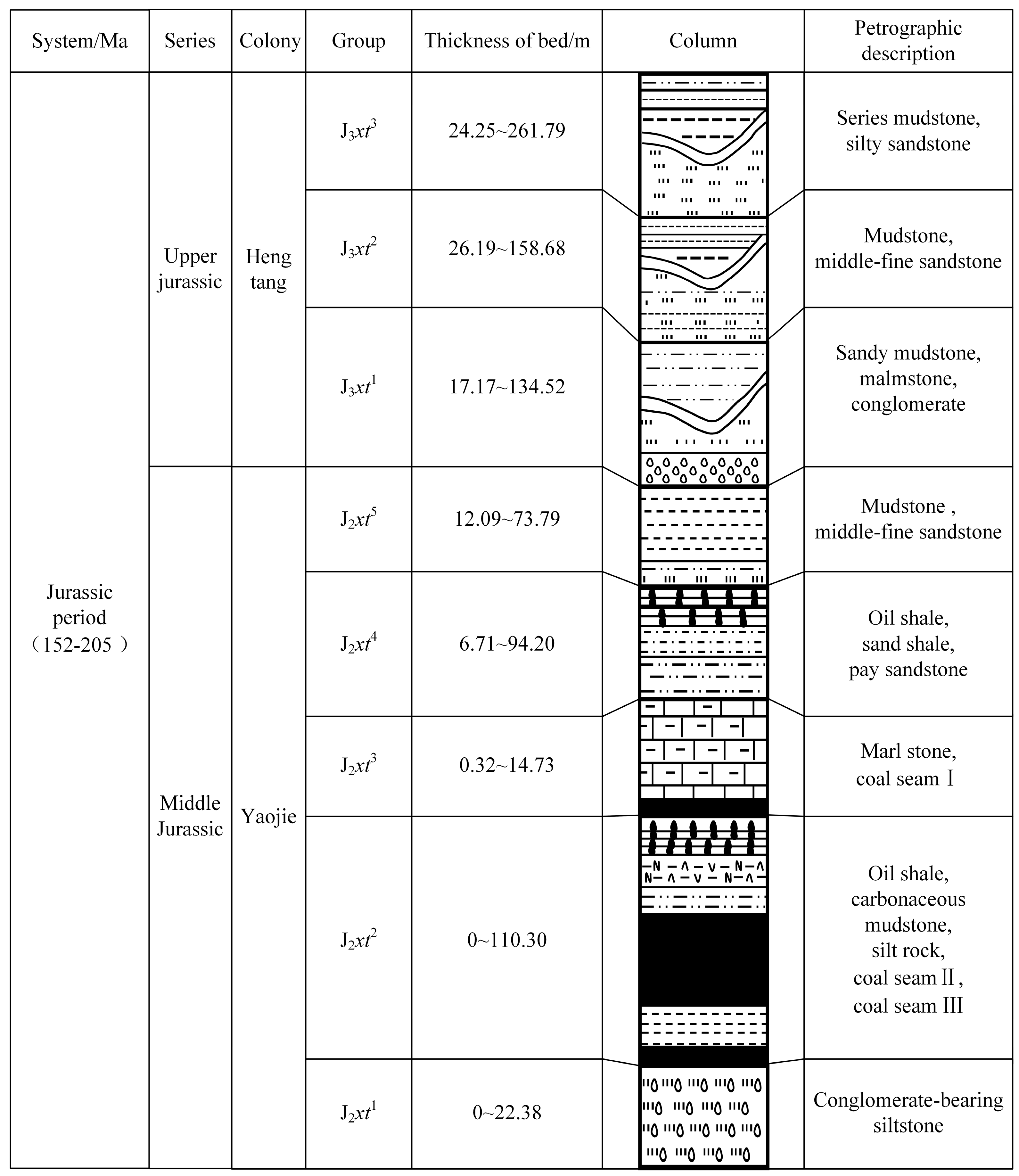
3.1.1. Geological Setting of the Study Area
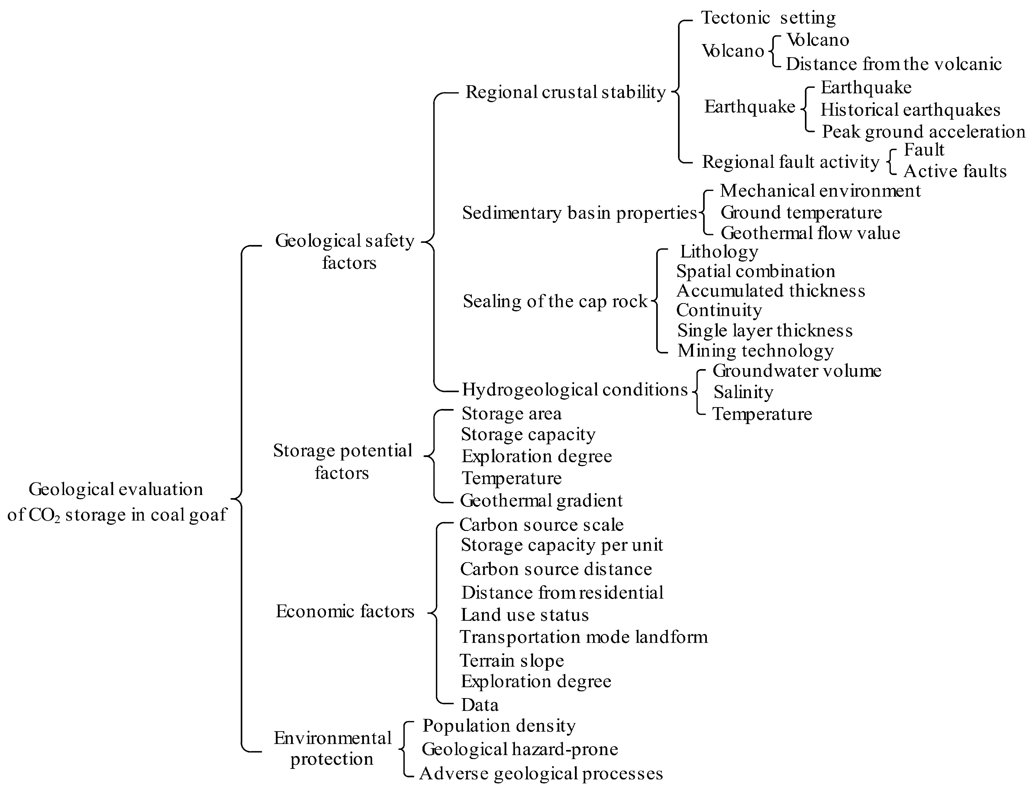
3.1.2. Classification of Influencing Factors
Geological Safety Factors
- (1)
- Regional crustal stability
- (2)
- Sedimentary basin properties
- (3)
- Sealing of the cap rock
- (4)
- Hydrogeological conditions
Storage Potential Factors
Economic Factors
Environmental Protection
3.1.3. Index Weight Determination
3.1.4. Classification of Geological Conditions for CO2 Storage
3.2. Comprehensive Evaluation
4. Conclusions
Author Contributions
Funding
Data Availability Statement
Conflicts of Interest
References
- Osman, A.I.; Hefny, M.; Abdel Maksoud, M.I.A.; Elgarahy, A.M.; Rooney, D.W. Recent advances in carbon capture storage and utilization technologies: A review. Environ. Chem. Lett. 2020, 192, 797–849. [Google Scholar] [CrossRef]
- Malik, S.; Makauskas, P.; Karaliute, V.E.; Pal, M.; Sharma, R. Assessing the geological storage potential of CO2 in Baltic Basin: A case study of Lithuanian hydrocarbon and deep saline reservoirs. Int. J. Greenh. Gas Con. 2024, 133, 104097. [Google Scholar] [CrossRef]
- Leung, D.Y.; Caramanna, G.; Maroto-Valer, M.M. An overview of current status of carbon dioxide capture and storage technologies. Renew. Sustain. Energy Rev. 2014, 39, 426–443. [Google Scholar] [CrossRef]
- Hurlbert, M.; Osazuwa-Peters, M. Carbon capture and storage in Saskatchewan: An analysis of communicative practices in a contested technology. Renew. Sustain. Energy Rev. 2023, 173, 113104. [Google Scholar] [CrossRef]
- Li, Q.; Wang, Y.L.; Wang, F.L.; Wu, J.P.; Tahir, M.U.; Li, Q.C.; Yuan, L.; Liu, Z.H. Effect of thickener and reservoir parameters on the filtration property of CO2 fracturing fluid. Energ. Source. Part A Recovery Util. Environ. Eff. 2019, 42, 1705–1715. [Google Scholar] [CrossRef]
- Ramadhan, R.; Abdurrahman, M.; Bissen, R.; Maneeintr, K. Numerical simulation of potential site for CO2 sequestration in a depleted oil reservoir in northern Thailand. Energy Rep. 2023, 9, 524–528. [Google Scholar] [CrossRef]
- Li, Q.C.; Liu, J.; Wang, S.M.; Guo, Y.; Han, X.Y.; Li, Q.; Cheng, Y.F.; Dong, Z.; Li, X.Z.; Zhang, X.D. Numerical insights into factors affecting collapse behavior of horizontal wellbore in clayey silt hydrate-bearing sediments and the accompanying control strategy. Ocean Eng. 2024, 297, 117029. [Google Scholar] [CrossRef]
- Sattar, U.; Latief, R.; Wang, Y.D.; Sattar, A.S. Green financial reporting framework for Paris Agreement parties. Front. Environ. Sci. 2024, 12, 1335547. [Google Scholar] [CrossRef]
- Weiler, J.; Tassinari, C.C.G.; De Aquino, T.F.; Bonetti, B.; Viola, V.O. Using mining waste for CO2 sequestration: Exploring opportunities through mineral carbonation, nature-based solutions, and CCUS. Int. J. Minin. Reclam. Environ. 2024, 2318132. [Google Scholar] [CrossRef]
- Fang, Z.Y.; Gao, Y.H.; He, W.; Zhu, M.B.; Xia, L.; Yang, P.Y.; Liu, D.S.; He, J. Carbonation curing of magnesium-coal slag solid waste backfill material: Study on properties of flow, mechanics and carbon sequestration. Case Stud. Constr. Mater. 2024, 20, e03204. [Google Scholar] [CrossRef]
- Fang, Z.Y.; Liu, L.; Zhang, X.Y.; Han, K.M.; Wang, J.Y.; Zhu, M.B.; Sun, W.J.; He, W.; Gao, Y.H. Carbonation Curing of Modified Magnesium-Coal Based Solid Waste Backfill Material for CO2 Sequestration. Process Saf. Environ. Prot. 2023, 180, 778–788. [Google Scholar] [CrossRef]
- Hassanpouryouzband, A.; Joonaki, E.; Vasheghani Farahani, M.; Takeya, S.; Ruppel, C.; Yang, J.; English, N.J.; Schicks, J.M.; Edlmann, K.; Mehrabian, H.; et al. Gas hydrates in sustainable chemistry. Chem. Soc. Rev. 2020, 49, 5225–5309. [Google Scholar] [CrossRef] [PubMed]
- Ali, M.; Jha, N.K.; Pal, N.; Keshavarz, A.; Hoteit, H.; Sarmadivaleh, M. Recent advances in carbon dioxide geological storage, experimental procedures, influencing parameters, and future outlook. Earth Sci. Rev. 2022, 225, 103895. [Google Scholar] [CrossRef]
- Shen, W.J.; Ma, T.R.; Zuo, L.; Yang, X.; Cai, J.C. Advances and Prospects of Supercritical CO2 for Shale Gas Extraction and Geological Sequestration in Gas Shale Reservoirs. Energy Fuels 2024, 38, 789–805. [Google Scholar] [CrossRef]
- Sang, S.X. The demand and mode of low-carbon development in carbon neutral coal industry. In Blue Book of Low Carbon Development, State Power Investment Group Co., Ltd., China International Economic Exchange Center; Social Science Literature Publishing House: Beijing, China, 2021; pp. 146–151. [Google Scholar]
- Wang, G.F.; Ren, S.H.; Pang, Y.H.; Qu, S.J.; Zheng, D.Z. Development achievements of China’ s coal industry during the 13th Five-Year Plan period and implementation path of “dual carbon” target. Coal Sci. Technol. 2021, 49, 1–8. [Google Scholar] [CrossRef]
- Annual Report Working Group on the Collaborative Path between Carbon Neutrality and Clean Air in China. Annu. Rep. China’s Carbon Neutrality Clean Air Synerg. Pathw. 2023, 2023, 3–10.
- Xie, G.; Liu, L.; Suo, Y.L.; Zhu, M.B.; Yang, P.; Sun, W.J. Study on the green disposal of industrial high salt water and its performance as activator to prepare magnesium-coal based solid waste backfill material for mine. J. Clean. Prod. 2024, 452, 141933. [Google Scholar] [CrossRef]
- Liu, L.; Wang, S.M.; Zhu, M.B.; Zhang, B.; Hou, D.Z.; Huan, C.; Zhao, Y.J. CO2 storage-cavern construction and storage method based on functional backfill. J. China Coal Soc. 2022, 47, 1072–1086. [Google Scholar] [CrossRef]
- Wang, S.M.; Shen, Y.J.; Sun, Q.; Liu, L.; Shi, Q.M.; Zhu, M.B.; Zhang, B.; Cui, S.D. Underground CO2 storage and technical problems in coal mining area under the “dual carbon” target. J. China Coal Soc. 2022, 47, 45–60. [Google Scholar] [CrossRef]
- Wang, S.M.; Kou, H.B.; Shen, Y.J.; Liu, L.; Gu, L.J.; Chen, X.; Li, Z.Y. Implications of CO2 outburst from coal⁃bearing rock series for the CO2 geological sequestration under shallow layers. J. Green Mine 2023, 1, 33–47. [Google Scholar]
- Li, S.G.; Zhang, J.F.; Bao, R.Y.; Ding, Y.; Bai, Y.; Zhou, Y.X.; Zhu, B. Research on the characteristics of CO2-water interface and the law of dissolution and mass transfer under the condition of carbon sequestration in goaf. J. China Coal Soc. 2024, 49, 513–527. [Google Scholar] [CrossRef]
- Ding, Y.; Tang, Y.Z.; Li, S.G.; Zhao, C.H.; Zhu, B.; Zhang, Y.Z.; Zhang, Y. Numerical simulation of well location deployment scheme for CO2 sequestration in old goaf. J. China Coal Soc. 2024, in press. Available online: https://link.cnki.net/urlid/11.2402.TD.20231204.1058.002 (accessed on 6 May 2024).
- Bachu, S.; Adaams, J.J.; Guo, S.J.; Dong, Y.Q. Carbon dioxide storage in geological media for climate change⁃capacity of deep saline aqui⁃fers to store dissolved carbon dioxide. Dyn. Hydrogeol. Eng. Geol. Technol. Method 2011, 13, 1–9. [Google Scholar] [CrossRef]
- Bielicki, J.M.; Leveni, M.; Johnson, J.X.; Ellis, B.R. The promise of coupling geologic CO2 storage with sedimentary basin geothermal power generation. Iscience 2023, 26, 105618. [Google Scholar] [CrossRef] [PubMed]
- Huang, D.G.; Yang, X.L.; Yu, Y.Q.; Liang, W.M. Technical progress of CO2 geological sequestration and CO2 sequestration by antiquated mine goaf. Clean Coal Technol. 2011, 17, 93–96. [Google Scholar] [CrossRef]
- Heidarabad, R.G.; Shin, K. Carbon Capture and Storage in Depleted Oil and Gas Reservoirs: The Viewpoint of Wellbore Injectivity. Energies 2024, 17, 1201. [Google Scholar] [CrossRef]
- Jiang, K.; Li, Z.P.; Dou, H.G.; Cao, Z.Y.; Hong, Y. Evaluation model of CO2 storage potential in Qinshui Basin. Spec. Oil Gas Reserv. 2016, 23, 112–114, 156. [Google Scholar]
- Singh, R.K.; Nayak, N.P.; Kumar, S. Effect of micro-fractures on gas flow behavior in coal for enhanced coal bed methane recovery and CO2 storage. Heliyon 2024, 10, 25914. [Google Scholar] [CrossRef] [PubMed]
- Hou, B.R.; Shangguan, S.T.; Niu, Y.H.; Su, Y.; Yu, C.F.; Liu, X.C.; Li, Z.Q.; Li, J.X.; Liu, X.; Zhao, K. Unique properties of rock salt and application of salt caverns on underground energy storage: A mini review. Energ. Source Part A Recovery Util. Environ. Eff. 2024, 46, 621–635. [Google Scholar] [CrossRef]
- Zhao, X.L.; Liao, X.W.; Wang, W.F.; Chen, C.Z.; Rui, Z.H.; Wang, H. The CO2 storage capacity evaluation: Methodology and determination of key factors. J. Energy Inst. 2024, 87, 297–305. [Google Scholar] [CrossRef]
- Kaldi, J.G.; Gibson-Poole, C.M. Storage Capacity Estimation, Site Selection and Characterization for CO2 Storage Projects—Report; CO2 CRC Report No. RPT08-1001; Cooperative Research Centre for Greenhouse Gas Technologies (CO2CRC): Canberra, Australia, 2008; pp. 12–25. [Google Scholar]
- Ye, J.P.; Feng, S.L.; Fan, Z.Q.; Wang, G.Q.; William, D.G. Micro⁃pilot test for enhanced coalbed methane recovery by injecting carbon dioxide in south part of Qinshui Basin. Acta Pet. Sin. 2007, 28, 77–80. [Google Scholar]
- Jia, J.Z.; Song, H.L.; Jia, P. Selective adsorption mechanism of CO2/CH4/N2 multi-component gas mixtures by N/S atoms and functional groups in coal. Process Saf. Environ. Prot. 2024, 182, 210–221. [Google Scholar] [CrossRef]
- Albertz, M.; Stewart, S.A.; Goteti, R. Perspectives on geologic carbon storage. Front. Energy Res. 2024, 10, 1071735. [Google Scholar] [CrossRef]
- Saaty, T.L. The Analytic Hierarchy Process; McGraw-Hill: New York, NY, USA, 1980; pp. 12–61. [Google Scholar]
- Butler, S.K.; Barajas-Olalde, C.; Yu, X.; Burton-Kelly, M.E.; Mibeck, B.A.F.; Kong, L.Y.; Kurz, B.A.; Crandall, D. Assessing pore network heterogeneity across multiple scales to inform CO2 injection models. Int. J. Greenh. Gas. Con. 2023, 130, 104017. [Google Scholar] [CrossRef]
- Guo, J.Q.; Wen, D.G.; Zhang, S.Q.; Xu, T.F.; Hu, Q.Y.; Li, X.F. Suitability Evaluation and Demonstration Project of CO2 Geological Storage in China; Geological Publishing House: Beijing, China, 2014; pp. 120–168. [Google Scholar]
- Zhang, S.Q.; Guo, J.G.; Li, X.F.; Fan, J.J.; Diao, Y.J. Geological Basis and Site Evaluation for Carbon Dioxide Geological Storage in China; Geological Publishing House: Beijing, China, 2011; pp. 60–98. [Google Scholar]
- GB 17741-2005; Seismic Safety Evaluation of Engineering Sites. China National Standardization Administration: Beijing, China, 2005.
- GB18306-2001; China Seismic Parameter Zoning Map. National Bureau of Quality and Technical Supervision: Beijing, China, 2001.
- Downey, M.W. Evaluating seals for hydrocarbon accumulations. AAPG Bull. 1984, 68, 1752–1763. [Google Scholar] [CrossRef]
- Ingram, G.M.; Urai, J.L. Top-seal leakage through faults and fractures: The role of mudrock properties. Geol. Soc. Lond. Spec. Publ. 1999, 158, 125–135. [Google Scholar] [CrossRef]
- Li, X.C.; Yuan, W.; Bai, B. A review of numerical simulation methods for geomechanical problems induced by CO2 geological storage. Rock Soil Mech. 2016, 37, 1762–1772. [Google Scholar] [CrossRef]
- Liang, M.G.; Fu, G.; Li, Q.Q.; Guo, H.Y.; Zhang, B.W. Fault Evolution and Its Effect on the Sealing Ability of Mudstone Cap Rocks. Energies 2022, 15, 7676. [Google Scholar] [CrossRef]
- Yang, B.; Fu, Q.; Liu, J.S.; Ma, W.R.; Zhao, S.J. Study on fault sealing of the Lishui West Sag in the East China Sea Basin. Front. Earth Sci. 2023, 10, 1012324. [Google Scholar] [CrossRef]
- Hubbert, M.K. Entrapment of Petroleum Under Hydrodynamic Conditions. AAPG Bull. 1953, 37, 1954–2026. [Google Scholar] [CrossRef]
- Wang, E.Y.; Yin, Q.C.; Shao, Q.; Zhang, A.S. Prediction indicators and critical values of regional outburst in unstable thick coal seam mining face with “three soft” characteristics. In Gas Geology Professional Committee of China Coal Society. Progress in Gas Geology Research 2013; China University of Mining and Technology Press: Beijing, China, 2013; p. 5. [Google Scholar]
- Celia, M.A.; Bachu, S.; Nordbotten, J.M.; Bandilla, K.W. Status of CO2 storage in deep saline aquifers with emphasis on modeling approaches and practical simulations. Water Resour. Res. 2015, 51, 6846–6892. [Google Scholar] [CrossRef]
- Shi, F.W.; Wang, K.; Lou, Y.; Su, C.; Lan, B.F.; Xia, P.; Shao, L.J.; Qin, C. Influence of Imbibition Fracturing Fluid on the Original Water and Methane Occurrence in Actual Coalbed Methane Reservoirs Using the Integrated Device of Displacement and Low-Field Nuclear Magnetic Resonance. Langmuir 2024, 40, 3063–3073. [Google Scholar] [CrossRef] [PubMed]
- Zhang, X.J. Study on CO2 Geological Utilization and Storage Potential in the Junggar Basin; China University of Geosciences: Beijing, China, 2020; pp. 52–89. [Google Scholar]

| Stage | Object | Evaluation | |||
|---|---|---|---|---|---|
| Objective | Method | Scale | Potential | ||
| Regional grade | Secondary structural units in sedimentary basins | Calculate the predicted storage potential and evaluate the geological storage prospect area | Data collection, remote sensing interpretation, field research, and comprehensive research | 1:50,000–1:200,000 | Predicting |
| Mine field grade | Third structural units in sedimentary basins | Select the target area for geological storage within the structural trap | Data collection, remote sensing interpretation, field research, and comprehensive research | 1:10,000–1:50,000 | Control |
| Mine grade | Coal goaf | Provide a basis for the engineering design of favorable storage goaf | Remote sensing interpretation, field research, comprehensive research, sample collection and testing, numerical simulation | 1:1000–1:10,000 | Basic |
| Perfusion grade | Unit in the goaf | Construction design and environmental monitoring | Comprehensive research, sample collection and testing, numerical simulation | 1:200–1:1000 | Sealing |
| Same | Slightly | Obvious | Notable | Very | Extraordinary | |
|---|---|---|---|---|---|---|
| Quota | 0.5 | 0.6 | 0.7 | 0.8 | 0.9 | 1 |
| Suitable | Above Average | Average | Below Average | |
|---|---|---|---|---|
| Tectonic setting | Craton Basin | Inland Rift Valley | Passive margin basin | Strike slip fault basin |
| Volcano | No | Low incidence area | Volcano occurrence area | Volcanic prone areas |
| Distance from the volcanic zone (km) | >250 | 100–250 | 25–100 | <25 |
| Earthquake | No | Low incidence area | Earthquake occurrence area | Earthquake prone areas |
| Historical earthquakes | Enclosed area | <4 | 4–6 | >4 |
| Peak ground acceleration (g) | <0.05 | 0.05–0.1 | 0.1–0.2 | >0.2 |
| Fault | No | Cracks, no faults | Mudstone filling fault | Deep faults, large cracks |
| Active faults | No active faults within 25 km | No active faults within 25 km, with unclear faults | No active faults within 10 km | No active faults within 10 km, with unclear faults |
| Suitable | Above Average | Average | Below Average | |
|---|---|---|---|---|
| Mechanical environment | Compressive | Compression torsion | Torsion | Tension–torsion, tension |
| Geothermal flow value (mW/m2) | <30 | 30–50 | 50–90 | >90 |
| Ground temperature (°C) | <1 | 1–2 | 2–4 | >4 |
| Suitable | Above Average | Average | Below Average | |
|---|---|---|---|---|
| Lithology | Mudstone, marl | Shale, sandy mudstone | Argillaceous siltstone | Sandstone |
| Single layer thickness | >20 m | 10–20 m | 2.5–10 m | <2.5 m |
| Accumulated thickness | >300 m | 100–300 m | 20–100 m | <20 m |
| Continuity | Regional distribution | Continuity of coalfield | Almost continuously | Uncontinual |
| Spatial combination | Many | 2 | 1 | No |
| Mining technology | Backfill | Mainly for backfill | Mainly for stope caving | Stope caving |
| Suitable | Above Average | Average | Below Average | |
|---|---|---|---|---|
| Groundwater volume | No | A little water | Water remains unchanged | Large |
| Salinity (g/L) | 30–50 | 10–30 | 0–10 | >50 |
| Temperature (°C) | <2 | 2–3 | 3–4 | >4 |
| Suitable | Above Average | Average | Below Average | |
|---|---|---|---|---|
| Storage area (km2) | >50 | 10–50 | 1–10 | <1 |
| Storage capacity (104t) | >500 | 100–500 | 10–100 | <10 |
| Exploration degree | Exploration | Part of exploration | General exploration | General investigation |
| Temperature (°C) | <−2 | −2–10 | 10–20 | >20 |
| Geothermal gradient (°C/100 m) | <2 | 2–3 | 3–4 | >4 |
| Suitable | Above Average | Average | Below Average | |
|---|---|---|---|---|
| Carbon source scale (104t/a) | >50 | 25–50 | 10–25 | <10 |
| Storage capacity per Unit area (104t/km2) | >150 | 50–150 | 10–50 | <10 |
| Carbon source distance (km) | <10 | 10–50 | 50–100 | >100 |
| Distance from residential areas (m) | >1200 | 1000–1200 | 800–1000 | <800 |
| Land use status | Deserts or unused land | Grassland and forest land | Cultivated land | Residential areas |
| Transportation mode | Pipeline | Short-distance road | Road | Railway |
| Landform | Dune | Hill | Flat land | Mountain |
| Terrain slope (°) | 0–5 | 5–10 | 10–25 | >25 |
| Exploration degree | Exploration | Part of exploration | General exploration | General investigation |
| Data | Sufficient and reliable | Sufficient data, generally reliable | Data and reliability are average | Insufficient |
| Suitable | Above Average | Average | Below Average | |
|---|---|---|---|---|
| Population density (/km2) | <25 | 25–50 | 50–100 | >100 |
| Geological-hazard-prone areas | No | Few | Hidden | Exist |
| Adverse geological processes | No | Few | Hidden | Exist |
| First-Level Parameter (A) | Second-Level Parameter (B) | Third-Level Parameter (C) | Fourth-Level Parameter (D) |
|---|---|---|---|
| Geological safety factors (A1) [0.45, 0.55] | Regional crustal stability (B1) 0.10 | Tectonic setting (C1) 0.10 | |
| Volcano (C2) 0.10 | Volcano (D1) 0.75 | ||
| Distance from the volcanic (D2) 0.25 | |||
| Earthquake (C3) 0.10 | Earthquake (D3) 0.65 | ||
| Historical earthquakes (D4) 0.35 | |||
| Regional fault activity (C4) 0.60 | Peak ground acceleration (D5) 0.15 | ||
| Fault (D6) 0.40 | |||
| Active faults (D7) 0.55 | |||
| Sedimentary basin properties (B2) 0.15 | Mechanical environment (C5) 0.60 | ||
| Geothermal flow value (C6) 0.20 | |||
| Ground temperature (C7) 0.20 | |||
| Sealing of the cap rock (B3) [0.60, 0.65] | Lithology (C8) 0.30 | ||
| Cap rock thickness (C9) [0.20, 0.30] | Single layer thickness (D8) [0.60, 0.70] | ||
| Accumulated thickness (D9) [0.30, 0.40] | |||
| Continuity (C10) 0.20 | |||
| Spatial combination (C11) [0.10, 0.15] | |||
| Mining technology (C12) [0.1, 0.2] | |||
| Hydrogeological conditions (B4) [0.10, 0.15] | Groundwater volume (C13) 0.60 | ||
| Salinity (C14) 0.10 | |||
| Temperature (C15) 0.30 | |||
| Storage potential factors (A2) 0.10 | Storage area (B5) [0.10, 0.20] | ||
| Storage capacity (B6) [0.55, 0.65] | |||
| Exploration degree (B7) 0.10 | |||
| Temperature (B8) 0.05 | |||
| Geothermal gradient (B9) 0.10 | |||
| Economic factors (A3) [0.15, 0.25] | Carbon source scale (B10) 0.10 | ||
| Storage capacity per unit (B11) 0.05 | |||
| Carbon source distance (B12) 0.35 | |||
| Distance from residential (B13) [0.05, 0.10] | |||
| Land use status (B14) [0.05, 0.10] | |||
| Transportation mode (B15) 0.10 | |||
| Landform (B16) 0.05 | |||
| Terrain slope (B17) 0.05 | |||
| Exploration degree (B18) 0.10 | |||
| Data (B19) 0.05 | |||
| Environmental protection (A4) 0.20 | Population density (B20) [0.45, 0.60] | ||
| Geological hazard-prone (B21) [0.20, 0.45] | |||
| Adverse geological processes (B22) 0.10 | |||
Disclaimer/Publisher’s Note: The statements, opinions and data contained in all publications are solely those of the individual author(s) and contributor(s) and not of MDPI and/or the editor(s). MDPI and/or the editor(s) disclaim responsibility for any injury to people or property resulting from any ideas, methods, instructions or products referred to in the content. |
© 2024 by the authors. Licensee MDPI, Basel, Switzerland. This article is an open access article distributed under the terms and conditions of the Creative Commons Attribution (CC BY) license (https://creativecommons.org/licenses/by/4.0/).
Share and Cite
Hou, D.; Xiao, Y.; Liu, L.; Huan, C. Combined Analytic Hierarchy Process and Weighted Interval Method Models for the Geological Evaluation of CO2 Storage in Coal Goaf. Energies 2024, 17, 2672. https://doi.org/10.3390/en17112672
Hou D, Xiao Y, Liu L, Huan C. Combined Analytic Hierarchy Process and Weighted Interval Method Models for the Geological Evaluation of CO2 Storage in Coal Goaf. Energies. 2024; 17(11):2672. https://doi.org/10.3390/en17112672
Chicago/Turabian StyleHou, Dongzhuang, Yifei Xiao, Lang Liu, and Chao Huan. 2024. "Combined Analytic Hierarchy Process and Weighted Interval Method Models for the Geological Evaluation of CO2 Storage in Coal Goaf" Energies 17, no. 11: 2672. https://doi.org/10.3390/en17112672