Article

Variable Frequency Resonant Controller Based on Generalized Predictive Control for Biased-Sinusoidal Reference Tracking and Multi-Layer Perceptron

1
Electrical Engineering Graduation Program, Federal University of Mato Grosso do Sul, Campo Grande 79070-900, MS, Brazil
2
Electrical Engineering Department, Federal University of Rio de Janeiro, Rio de Janeiro 21941-614, RJ, Brazil
3
Institute of Chemistry, Federal University of Mato Grosso do Sul, Campo Grande 79070-900, MS, Brazil
4
Oak Ridge National Laboratory—ORNL, Oak Ridge, TN 37830, USA
*
Author to whom correspondence should be addressed.
Energies 2024, 17(12), 2801; https://doi.org/10.3390/en17122801
Submission received: 4 May 2024 / Revised: 30 May 2024 / Accepted: 5 June 2024 / Published: 7 June 2024
(This article belongs to the Section B: Energy and Environment)

Abstract

:
Resonant controllers are widely used in power electronics to track sinusoidal references. According to the internal model principle (IMP), these controllers should embed the poles of the Laplace or Z transform of the reference for the closed-loop system to track the reference asymptotically. Thus, tracking a sinusoidal reference is difficult as the controller should adapt its structure to embed the poles of the sinusoidal reference with variable frequency, as those poles depend on that variable frequency. On the other hand, Generalized Predictive Control (GPC) is widespread in industry applications due to its fast response, robustness and capability to include constraints. Resonant controllers based on GPC, which satisfy IMP, have been developed. However, these controllers consider the sinusoidal frequency to be constant. This paper presents a new GPC-based resonant controller with an adaptive and simple control law to track references with variable frequencies. A PLL estimates the frequency of the reference. A multi-layer perceptron uses the estimated frequency to define the gain matrix required to calculate the GPC control action. The GPC control action and the estimated frequency define the control law, which satisfies IMP in steady-state conditions. The authors did not find in the literature the proposed mathematical development of an adaptive GPC resonant controller with a discrete-time augmented model whose control law satisfies IMP. Thus, the proposed approach is helpful to develop other adaptive predictive controllers. Experimental results show that the proposed controller can track sinusoidal references whose frequencies vary in time.

1. Introduction

Nowadays, Model Predictive Control (MPC) is a popular control strategy in power electronics, motor drives and other applications. MPC is based on the prediction of the plant responses. The control law is calculated to minimize a cost function used to evaluate the control performance that depends on the predicted plant responses [1,2,3,4,5].
The control values are finite in the Finite Control Set Model Predictive Control (FCS-MPC). FCS-MPC can be applied to inverters and other converters whose outputs depend on a finite set of control signals. For example, a two-level, three-phase inverter that controls a three-phase motor only produces eight switching states. Thus, FCS-MPC estimates the switching state that allows getting the desired future response of the plant [6,7]. Generalized Predictive Control (GPC) is another predictive control approach, which is based on an augmented prediction model and an optimization process that allows calculating a set of future control actions that reduces the future errors [8,9,10,11,12]. GPC has fast response, robustness and restrictions in the input and output, which can be considered to obtain the control law. Differently from FCS-MPC, the control action calculated in GPC can have many values (within the constraints defined in the optimization process).
On the other hand, resonant controllers are widely applied in power electronics (e.g., active power filters, power factor corrections and the connection of photovoltaic systems to the grid) [13,14,15,16,17,18]. According to the internal model principle (IMP), a high-performance tracking controller must embed the model of the references to be asymptotically tracked and the model of the perturbations to be asymptotically rejected [10,19,20,21,22]. The model of a signal can be the poles of the Laplace or Z transform of that signal. Hence, a resonant controller should have the model of the sinusoidal signal to track that kind of reference. The continuous-time transfer function of an ideal resonant controller is G r e s ( s ) = s 2 s 2 + ω 2 , where ω is the frequency of the sinusoidal reference to be tracked. The poles of G r e s ( s ) , ± j ω equal the poles of the Laplace transform of a sinusoidal signal [23]. As a result, a resonant converter satisfies the requirements of IMP. However, ideal resonant controllers are difficult to implement in digital processors. Therefore, a damping factor ε is usually added to a resonant converter to avoid implementation problems. The poles of this new controller, called a quasi-resonant controller, are ε ± ε 2 ω 2 , which are different from those of the Laplace transform of a sinusoidal signal. Hence, quasi-resonant controllers have a steady-state tracking error as these controllers do not satisfy the requirements of IMP [23].
Some applications require tracking a sinusoidal signal whose frequency varies in time [24,25,26,27]. In that case, the poles of the reference (in steady state) are not constant. Hence, the structure of the resonant controller should change so that its poles are equal to the poles that model the sinusoidal reference for the controller to satisfy IMP. However, changing the structure of a controller while having a good transient response is not straightforward.
Different approaches for developing controllers capable of tracking sinusoidal references or rejecting sinusoidal disturbances were proposed in the literature. A modified quasi-resonant controller for a permanent magnet synchronous motor is presented in [14]. In [28], a cascade resonant control structure for a voice coil DC motor is proposed, using a new speed resonant controller whose transfer function is K r c ( s ) = K v ( s + α ) 2 s 2 + ω 2 , with ω being the sinusoidal reference frequency, while K v and α are tuning parameters. However, its methodology is restricted to a DC motor operating at low frequencies (1 Hz in experimental tests), and the frequency of the resonant controller is fixed. The approach in [9] uses a CARIMA (auto-regressive moving average) model to control a doubly fed induction generator (DFIG) wind turbine for tracking a time-varying power reference signal that depends on the frequency deviation in a microgrid. An IIR filter, a repetitive control system and virtual variable sampling were applied in [24] to control an active power filter. The application of deep learning to develop a resonant controller is explained in [29]. The resonant controller in [30] uses a fuzzy logic system to obtain adaptive gains for the controller. In contrast, genetic algorithms were used in [31,32] to obtain the optimal gains of resonant controllers. The approach in [33] applies the GPC technique to define a controller capable of tracking or rejecting biased sinusoidal signals while satisfying IMP. This approach defines a space-state augmented model that embeds the Z-transform of a sinusoidal signal and allows for predicting future errors. However, this approach’s augmented model and control law structure are calculated considering that the sinusoidal reference frequency is a fixed parameter.
This paper improves the controller in [33] with an adaptive control law that provides the possibility for the control and implementation of variable frequency references. A SISO (Single-Input, Single-Output) plant is used to validate the controller. The reference frequency is estimated through a PLL. A multi-layer perceptron (MLP) calculates the GPC gain matrix as a function of the PLL estimation. Different from [29], the proposed controller calculates the control law using a few artificial neurons. The GPC state vector and the plant input are also calculated using the estimated frequency function. Thus, the proposed controller has a low computational cost and a simple structure. It is proved that, in steady state conditions, the proposed control law satisfies IMP, allowing the asymptotic tracking of the reference. Experimental tests using the DSP dSpace DS1104 prove that the proposed approach can track sinusoidal references with varying frequency.
The proposed approach is based on developing an adaptive GPC-based resonant controller based on a discrete-time augmented prediction model whose control law satisfies IMP. Thus, it is possible to apply robust analysis and design tools such as singular value decomposition (SVD), similarity transformation applied to square matrix functions, condition number to analyze the numerical stability of a solution, the design of state estimators (e.g., Luenberger observer) and others. In other works of literature, the authors did not find the proposed mathematical development of a GPC-based resonant controller with an adaptive control law that satisfies IMP and is based on discrete space-state augmented models. Thus, the mathematical background presented in this work can be applied to develop other GPC-based controllers (e.g., resonant controllers).
The remainder of the paper is organized as follows: Section 2 describes the mathematical structure of a generalized predictive control for tracking biased sinusoidal reference. This section also explains the internal model principle and the problems generated when the sinusoidal reference frequency varies in time. The methodology to design the proposed resonant controller for sinusoidal references with variable frequency is described in Section 3. Experimental results shown in Section 4 prove that the proposed controller can track variable frequency sinusoidal references. Finally, conclusions are outlined.

2. Background and Literature Review

This section describes the mathematical background and literature review of the generalized predictive control (GPC) applied in tracking biased-sinusoidal references, the internal model principle (IMP) and the impact of a variable sinusoidal reference frequency in a resonant controller. In this section, k is the discrete-time, Q n × m represents that Q is an n × m matrix and Z [ ] denotes the Z transform.

2.1. Generalized Predictive Control for the Tracking of Biased-Sinusoidal References

The mathematical analysis of the generalized predictive control for tracking biased-sinusoidal references developed in this subsection is based on [33]. Equations (1) and (2) represent the discrete-time space-state model of a SISO (Single-Input, Single-Output) plant with order n [34,35]:
x k + 1 = A x k + B u k ,
y k = C x k ,
where A n × n , B n × 1 , C 1 × n , x k n × 1 is the state vector at instant k, u k is the input and y k is the output. The matrices A, B and C can be obtained through the discretization process (e.g., forward Euler method or Tustin method) of the continuous-time space-state model of the plant [36,37,38]. Equation (3) defines the tracking error e k :
e k = r k y k = r k C x k ,
A continuous-time biased-sinusoidal reference can be represented as r ( t ) = m 0 + m 1 sin ( ω t ) , where m 0 is the bias, m 1 is the sinusoidal amplitude and ω is the sinusoidal frequency. The reference r ( t ) is discretized by making t = t s k , with t s being the sampling time. Thus, the discretized biased-sinusoidal reference ( r k ) is defined as in (4).
r k = m 0 + m 1 sin ( ω t s k ) = m 0 + m 1 sin ( Ω k ) ,
where Ω is the discrete angular frequency:
Ω = ω t s .
Applying trigonometric properties into (4) allows proving that the reference at instant k + 1 , i.e., r k + 1 , is a linear combination of r k , r k 1 and r k 2 , as shown in (6):
r k + 1 = γ r k γ r k 1 + r k 2 ,
where γ depends on the discretized frequency Ω , as indicated in (7):
γ = 2 cos ( Ω ) + 1 .
Equation (3) allows proving that r k i = e k i + C x k i , for i = 0 , 1 , 2 . Thus, (6) can be rewritten as in (8):
r k + 1 = γ ( e k + C x k ) γ ( e k 1 + C x k 1 ) + ( e k 2 + C x k 2 ) = γ e k γ e k 1 + e k 2 + C [ γ x k γ x k 1 + x k 2 ] .
Equation (9) defines the future error at instant k + 1 , i.e., e k + 1 :
e k + 1 = r k + 1 y k + 1 = r k + 1 C x k + 1 .
Substituting (8) into (9) yields
e k + 1 = γ e k γ e k 1 + e k 2 + C x k + 1 + γ x k γ x k 1 + x k 2 .
On the other hand, (1) allows deducing (11):
x k i = A x k ( i + 1 ) + B u k ( i + 1 ) , i = 1 , 2 , . . .
Applying (11) into (10) allows expressing e k + 1 as follows:
e k + 1 = γ e k γ e k 1 + e k 2 + C [ ( A x k B u k ) + γ ( A x k 1 + B u k 1 ) γ ( A x k 2 + B u k 2 ) + ( A x k 3 + B u k 3 ) ] = γ e k γ e k 1 + e k 2 + C A [ x k 3 γ x k 2 + γ x k 1 x k ] + C B [ u k 3 γ u k 2 + γ u k 1 u k ] = γ e k γ e k 1 + e k 2 + C A q k + C B v k ,
where
q k = x k 3 γ x k 2 + γ x k 1 x k ,
v k = u k 3 γ u k 2 + γ u k 1 u k .
Equations (11), (13) and (14) allows proving (15):
q k + 1 = x k 2 γ x k 1 + γ x k x k + 1 = ( A x k 3 + B v k 3 ) γ ( A x k 2 + B v k 2 ) + γ ( A x k 1 + B v k 1 ) ( A x k + B v k ) = A ( x k 3 γ x k 2 + γ x k 1 x k ) + B ( u k 3 γ u k 2 + γ u k 1 u k ) = A q k + B v k .
Equations (12) and (15) allow deducing the GPC augmented model that will be used in to create the proposed resonant controller:
x ̲ k + 1 = A ̲ x ̲ k + B ̲ v k ,
y ̲ k = e k = C ̲ x ̲ k ,
where v k is the model input (action control), y ̲ k is the model output and x ̲ k is the model state vector, while
x ̲ k = q k e k 2 e k 1 e k , x ̲ k + 1 = q k + 1 e k 1 e k e k + 1 , A ̲ = A O n O n O n 0 0 1 0 0 0 0 1 C A 1 γ γ , B ̲ = B 0 0 C B , C ̲ = O n T 0 0 1 ,
where O n is a n × 1 vector composed by zeros. Equation (13) allows proving that q k has the same number of elements of x k (n elements), as q k is a combination of x k , x k 1 , x k 2 and x k 3 . Hence, x ̲ k is a ( n + 3 ) × 1 vector. Furthermore, note that (12) allows deducing the last state variable e k + 1 of x ̲ k + 1 in the augmented model state equation defined in (16).
Equations (16) and (17) can be used recursively to estimate the future errors as a function of the augmented model state vector x ̲ k and the future control actions, as indicated in [34]. For example, x ̲ k + 2 = A ̲ x ̲ k + 1 + B ̲ v k + 1 = A ̲ [ A ̲ x ̲ k + B ̲ v k ] + B ̲ v k + 1 = A ̲ 2 x ̲ k + A ̲ B ̲ v ̲ k + B ̲ v k + 1 . Thus, y ̲ k + 2 = C ̲ x ̲ k + 2 = C ̲ A ̲ 2 x ̲ k + C ̲ A ̲ B ̲ v ̲ k + C ̲ B ̲ v k + 1 . We define E and V as the vector of the future responses ( e k + 1 , e k + 2 , , e k + n p ) and the vector of future control actions ( v k , v k + 1 , , v k + n c 1 ), respectively:
E = e k + 1 e k + 2 e k + n p T ,
V = v k v k + 1 v k + n c 1 T ,
where n p and n c are the size of the prediction window and the control window, respectively, being n c n p . The vector of predicted responses can be estimated as follows [34]:
E = F x ̲ k + Φ V ,
where
F = C ̲ A ̲ C ̲ A ̲ 2 C ̲ A ̲ 3 C ̲ A ̲ n p ,
Φ = C ̲ B ̲ O O O C ̲ A ̲ B ̲ C ̲ B ̲ O O C ̲ A ̲ 2 B ̲ C ̲ A ̲ B ̲ C ̲ B ̲ O C ̲ A ̲ n p 1 B ̲ C ̲ A ̲ n p 2 B ̲ C ̲ A ̲ n p 3 B ̲ C ̲ A ̲ n p n c B ̲ ,
where A ̲ , B ̲ and C ̲ are the matrices of the augmented model defined in (18).
The cost function in (24) is used to evaluate the performance of the predictive control in function to the future errors e k + 1 , e k + 2 , , e k + n p .
J = E T E + V T R w V , R w = r w I c ,
where I c is an n c × n c identity matrix, while r w is a tuning parameter: the greater the value of r w , the more important the minimization of the magnitude of V in the solution. The optimal solution V o p for J makes J V = 0 . Substituting (21) into (24), and after some mathematical manipulations, the optimal solution of J is [34]:
V o p = ( Φ T Φ + R w ) 1 Φ T F x ̲ k .
The receding horizon control strategy states that only the first element of V o p in (25), i.e., v ̲ k , is used to calculate the plant input (control law). Therefore, according to (25),
v k = [ 1 0 0 ] N c elements V o p = [ 1 0 0 ] ( Φ T Φ + R w ) 1 Φ T F K r x ̲ k ,
where K r is the GPC gain matrix. In a SISO plant, K r is a 1 × ( n + 3 ) vector, due to x ̲ k also having n + 3 elements.
Substituting (26) into (14) allows deducing the plant input u k :
u k = u k 3 + γ ( u k 1 u k 2 ) v k .

2.2. Internal Model Principle and Variable Frequency Resonant Controller

Let R ( z ) = N ( z ) D ( z ) be the Z transform of the discretized reference r k , where N ( z ) and D ( z ) are coprime (have no common factors). Let G ( z ) be the plant transfer function. The internal model principle (IMP) states that if the controller (or the plant) has the poles of R ( z ) , i.e., the roots of D ( z ) , and these poles are not canceled, then the plant output will asymptotically track the reference [39,40,41].
Let G ( z ) and G a ( z ) be the discrete transfer functions of the plant and the GPC augmented model, respectively. Block algebra allows proving (28) [33]:
G a ( z ) = z 3 ( z 1 ) z 2 2 cos ( Ω ) z + 1 G ( z ) .
The internal model principle (IMP) states that the output of a closed-loop control system will asymptotically track a reference if the poles of the Z transform of that reference are embedded into the controller, without zero-pole cancellations [19,20,22]. The term 1 ( z 1 ) ( z 2 2 cos ( Ω ) z + 1 ) in (28) contains the poles of a step and a sinusoidal signal with frequency Ω . Hence, a GPC strategy that satisfies (28) will track the desired reference. Besides, IMP also states that the controller will reject perturbations whose poles of its Z -transform are equal to the poles of G a ( z ) in (28).
However, (28) considers that Ω is constant and known. Note that the augmented model state matrix A ̲ in (18), the GPC gain matrix K r in (26) and u k in (27) depend on the γ that depend on Ω . However, variable frequency resonant controllers must track a sinusoidal signal whose frequency varies in time. As a result, Ω is not constant. Therefore, the control law in (27) does not satisfy IMP when the frequency of the sinusoidal reference varies in time.

3. Methodology for the Design of the Proposed Variable Frequency Resonant Predictive Controller

This section explains the design of a resonant controller, based on generalized predictive control (GPC), to track a sinusoidal reference with variable frequency. Besides, it is proved that the proposed approach satisfies the internal model principle (IMP).
Figure 1 shows the structure of the proposed control. In the first place, a PLL estimates the frequency of the sinusoidal reference ( f e ). That PLL can be discarded if the frequency is known. The estimated frequency f e is used in (5) to obtain the estimated discrete frequency Ω e :
Ω e = 2 π f e t s .
Replacing Ω with its estimation Ω e in (7) allows obtaining the estimation of γ , denoted as γ e :
γ e = 2 cos ( Ω e ) + 1 .
Usually, it is possible to define the range of values the sinusoidal reference frequency will take. That means Ω e will have a maximum value ( Ω m a x ) and a minimum value ( Ω m i n ):
Ω m i n Ω e Ω m a x .
A multi-layer perceptron (MLP) is used to estimate the GPC gain matrix K r in the function of Ω e to obtain a good transient response for different reference frequencies. The MLP used in this work does not consider the GPC parameters ( N p , N c and r w ) as inputs for the following reasons:
  • The GPC parameters are constants in most GPC-based applications.
  • Even if it was necessary to modify the GPC parameters to obtain the matrix gain that gives a good transient response for different frequencies, these new GPC parameters would also depend on Ω (i.e., these parameters are a function of Ω ). Hence, the gain matrix is a function of Ω :
    K r = Ψ 1 ( n p , n c , r w , Ω ) = Ψ 1 ( n p ( Ω ) , n c ( Ω ) , r w ( Ω ) , Ω ) = Ψ 2 ( Ω )
    where Ψ 1 and Ψ 2 represent mathematical functions.
The training data for the MLP are composed of the values of K r for different values of Ω after setting the GPC parameters ( N p , N c and r w ) and the variation range of the estimated discretized frequency according to (31). The MLP has one input ( Ω e ) and n + 3 outputs (due to the gain matrix being a 1 × ( n + 3 ) vector, as mentioned before). The gain matrix estimated by the MLP is called K r M L P .
Let q ¯ k , v ¯ k and x ¯ ̲ k be the estimations of q k , v k and e x ̲ k , respectively. These estimations are obtained by substituting γ for γ e in (13), (14) and (18). Thus,
q ¯ k = x k 3 γ e x k 2 + γ e x k 1 x k ,
v ¯ k = u k 3 γ e u k 2 + γ e u k 1 u k .
x ¯ ̲ k = q ¯ k e k 2 e k 1 e k
Substituting x ̲ k with x ¯ ̲ k in (26) gives the proposed GPC control action v ¯ k in (34):
v ¯ k = K r M L P x ¯ ̲ k .
From (34),
u k = u k 3 + γ e ( u k 1 u k 2 ) v ¯ k .
The proposed control law (the plant input) in (38) is obtained by substituting (36) into (37):
u k = u k 3 + γ e ( u k 1 u k 2 ) K r M L P x ¯ ̲ k ,
Let us assume that γ e achieves a steady-state condition. Under this assumption, applying the Z transform into (37) is possible. Thus, after mathematical manipulations, the transfer function between u k and v ¯ k can be obtained as follows:
Z [ u k ] Z [ v ¯ k ] = z 3 1 γ e z + γ e z 2 z 3 = z 3 ( z 1 ) z 2 2 cos ( Ω e ) z + 1 .
The poles of z 3 ( z 1 ) z 2 2 cos ( Ω e ) z + 1 in (39) are the poles of the Z transform of a step signal and the sinusoidal signal with frequency Ω e . As a result, the proposed controller in steady-state embeds the model of the reference, satisfying IMP.
The empirical implementation of the proposed controller was performed based on the following considerations:
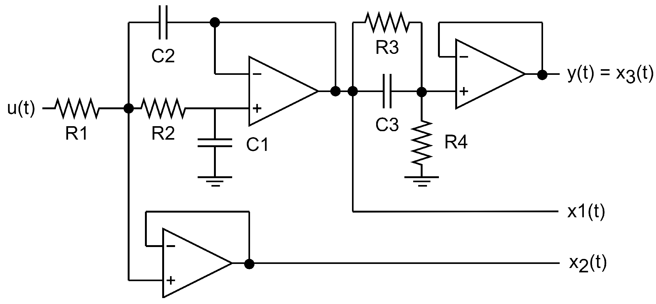
  • Plant: a third-order plant with a zero was used in the experimental test. This plant was created using capacitors, resistors and the operational amplifier AD713JN. Figure 2 shows the schematic diagram of the plant. The signals x 1 ( t ) , x 2 ( t ) and x 3 ( t ) are the state variables of the plant, which are sent to the analog-to-digital converters of the digital processor where the control algorithm is implemented (in this work, the processor is a dSpace DS1104). The transfer function of the plant is as follows:
    G ( s ) = R 4 ( R 3 C 3 s + 1 ) [ R 1 R 2 C 1 C 2 s 2 + ( R 1 + R 2 ) C 1 s + 1 ] [ R 3 R 4 C 3 s + ( R 3 + R 4 ) ]
    Most adaptive resonant or quasi-resonant converters are applied in power electronics devices [42,43,44,45,46]. In those cases, it is difficult to know if the control strategy produces a ripple in the tracking error or for other reasons (current or voltage harmonics, electromagnetic interference, etc.). Using a plant based on an operational amplifier makes the analysis of the error produced by the control system easier. The mean square error (MSE) and the output settling time will be used to measure the controller’s performance.
  • MLP: The MLP has a hidden layer with a tan-sig activation function and an output layer with a linear activation function. The number of neurons in the output layer is n + 3 (the size of K r ). The small number of hidden neurons should be used to obtain an adequate estimation of K r M L P with low computational cost. In this work, two hidden neurons was enough to obtain a mean square error less than 10 4 (negligible).
  • PLL: a conventional PID-based PLL was used to estimate the frequency of the sinusoidal reference. The proportional, integral and derivative gains of the PID are 580, 3800 and 1, respectively. The frequency estimation is beyond the objectives of this work.

4. Results

This section shows the experimental results that prove the performance of the proposed predictive controller.
The proposed GPC-based controller was experimentally implemented using the DSP dSpace DS1104, as shown in Figure 3. The plant used in the tests has the structure indicated in Figure 2, where R 1 = 10 k Ω , R 2 = 15 k Ω , R 3 = R 4 = 39 k Ω , C 1 = 47 n F and C 2 = C 3 = 100 n F . The signals x 1 ( t ) , x 2 ( t ) and x 3 ( t ) are the state variables, while u ( t ) and y ( t ) are the input and the output of the plant, respectively. According to (40), the transfer function of this plant is
G ( s ) = 1.418 × 10 6 s + 3.637 × 10 8 s 3 + 2179 s 2 + 2.273 × 10 6 s + 7.274 × 10 8 .
This plant was discretized considering t s = 0.5 ms. The discrete-time space-state model of this plant is composed of the following matrices:
A = 0.413 0.454 0 0.240 0.788 0 0.437 0.422 0.774 , B = 0.1331 0.4528 0.1273 , C = [ 0 0 1 ] .
The MLP was trained using the gain matrices obtained considering N p = 40 , N c = 10 , r w = 0.05 and 0.15 Ω 0.19 (to include frequencies between 50 Hz and 60 Hz). The MLP has one input, two artificial neurons with tan-sig activation function in the hidden layer and six neurons in the output layer representing the elements of K r M L P . The signal Ω e was normalized within the range [ 0 1 ] before the training of the MLP.
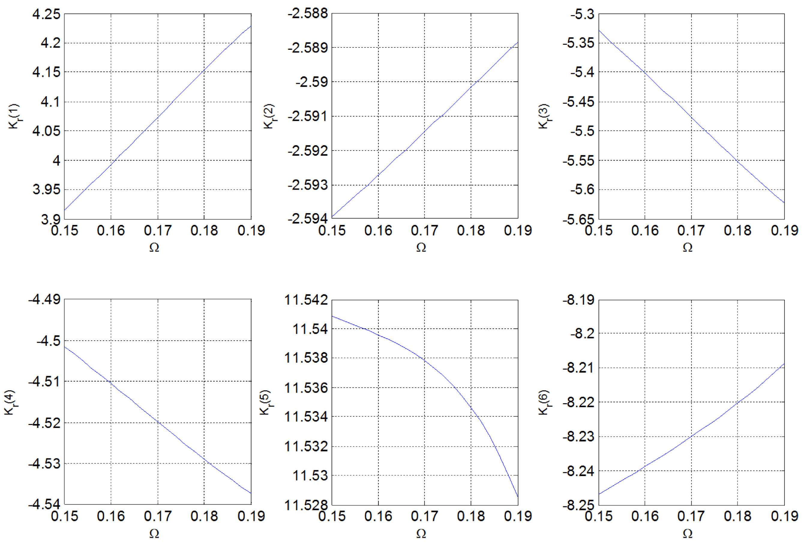
Figure 4 illustrates the elements of the gain matrix K r , which, for this application, forms a six-dimensional vector across different Ω values used to train the MLP. Observe that the elements of K r are different functions of Ω (linear, quadratic or more complex functions). For that reason, an MLP was used to estimate these parameters.
Two tests were performed to prove the performance of the proposed controller:
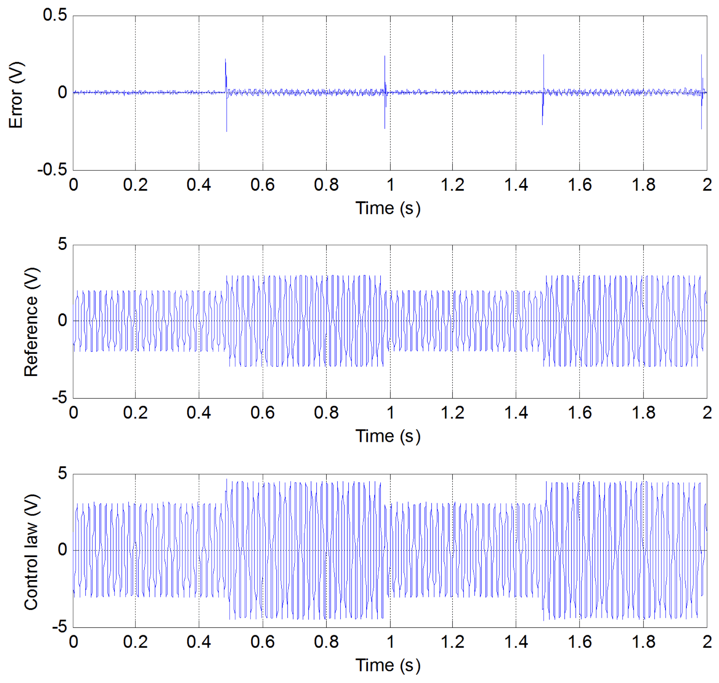
  • Test 1: The reference is sinusoidal with 3 V amplitude and 60 Hz frequency. After 0.5 s, it has an amplitude of 2 V and a frequency of 50 Hz.
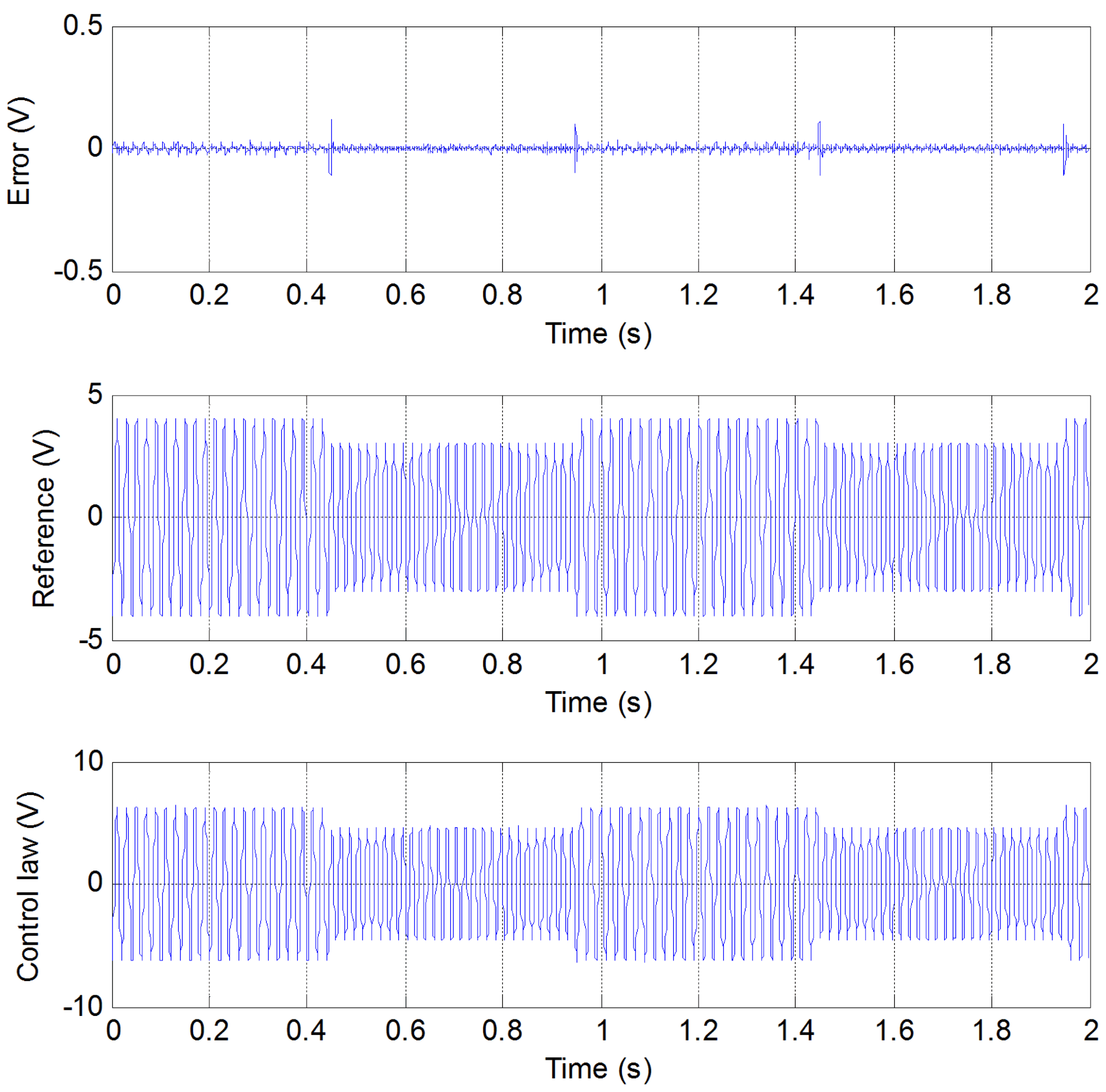
  • Test 2: The reference is a sinusoidal reference with 4 V amplitude and 50 Hz frequency. After 0.5 s, the reference has an amplitude of 3 V and a frequency of 55 Hz.
In both tests, the frequency and amplitude of the reference signal change every 0.5 s.
Figure 5 and Figure 6 show the error, the reference and the control law for the two tests. In both cases analyzed, the steady-state error tends to be zero. The error spikes are expected because the abrupt amplitude and frequency reference change generates them. Furthermore, the proposed controller has a fast-tracking response, where spikes disappear. The abrupt change in the amplitude and frequency of the references produces spikes in the error curves. However, these spikes disappear quickly, proving that the proposed controller has a fast response.
Table 1 shows the mean square error (MSE) and the average duration of the spikes in the error curves (i.e., the settling time required for the controller to produce a steady state output) for each test. Both MSEs are low, with the MSE for the second test being the lowest between them. The results prove that the proposed approach allows tracking sinusoidal references with variable frequencies. The settling times in both tests are similar and small, proving that the proposed controller has a fast response. The proposed approach considers that the PLL gives a good reference frequency estimation.
The proposed approach was compared with the following techniques:
  • The resonant controller in [33], working considering a fixed frequency of 55 Hz. The GPC parameters ( n p , n c , r w ) for this controller are equal to the parameters used in the proposed approach.
  • The adaptive proportional quasi-resonant controller with the transfer function G r e s ( s ) = 4 + 600 s 2 + 0.04 s + ω e 2 , with ω e = 2 π f e being the angular frequency (in rad/s) estimated by the PLL. This controller is based on [43].
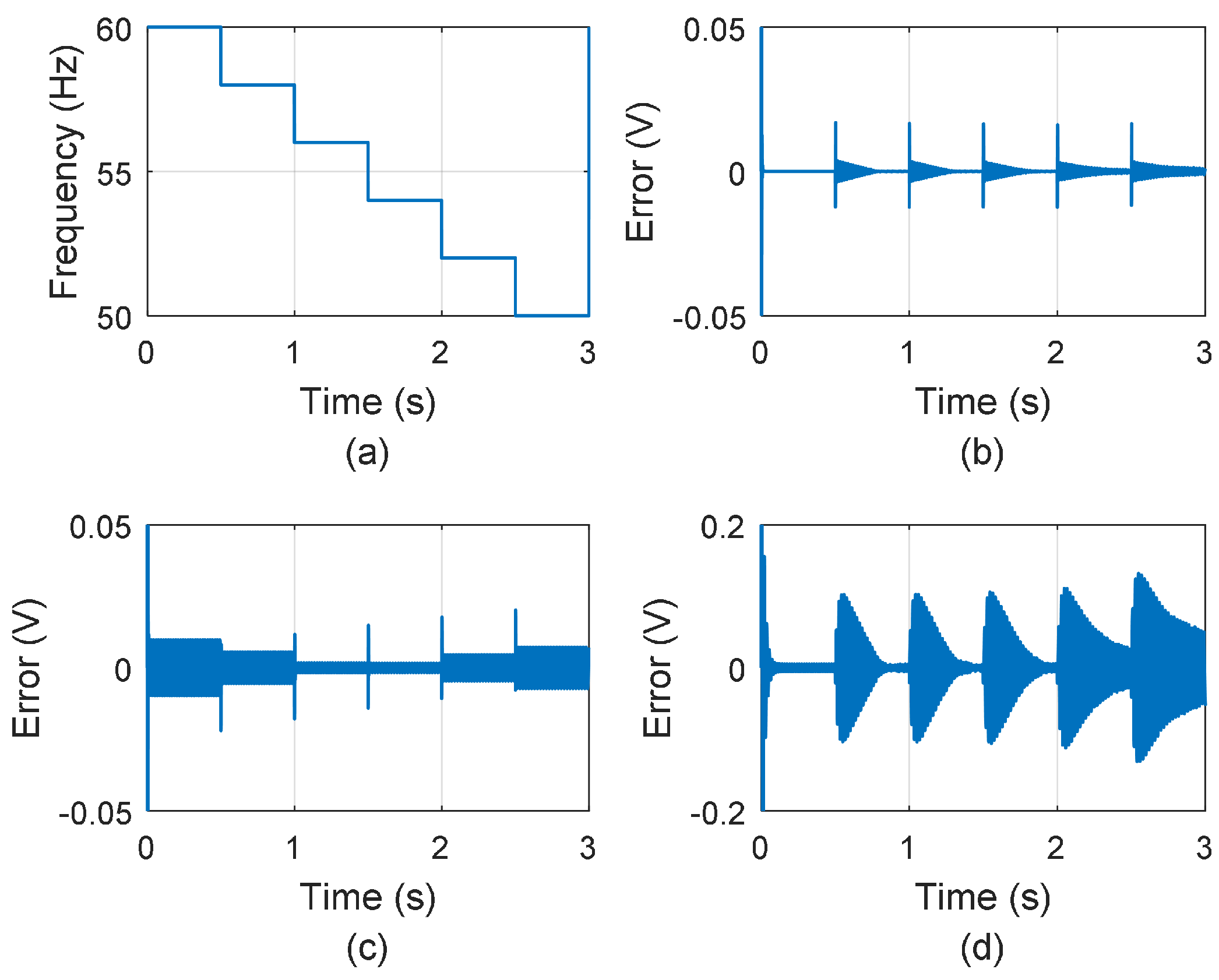
These techniques were tested through simulations performed in MATLAB 2021b. The sinusoidal reference with an amplitude of 2 V and a frequency that varies from 60 Hz to 50 Hz in steps of 2 Hz every 0.5 s. Figure 7 shows the errors for each controller. The proposed approach has the lowest error ripple.
Table 2 shows the mean square error (MSE) for each controller. As shown in Figure 7, the proposed adaptive resonant controller based on GPC has lower MSE than the other approaches. These results prove the good performance of the proposed controller.

5. Discussion

This section will theoretically compare the proposed controller and other approaches in the literature. Advantages, limitations and future research directions will also be analyzed.
The proposed resonant controller was designed to track sinusoidal references with variable frequency. The design of the MLP used to obtain K r M L P considered the steady-state responses. More research should be conducted concerning the stability during the change in frequency. However, the proposed controller was stable for a step in the reference frequency.
Most adaptive resonant or quasi-resonant controllers in literature are applied mainly in power electronics, where the output system is affected by electromagnetic interference, current/voltage harmonics and others [42,43,44,45,46]. In those cases, it is difficult to define if the experimental tracking error is produced by limitations of the controller or from other external sources. Besides, there is no guarantee that those approaches can be applied to other kinds of plants. On the other hand, the proposed approach gives a general mathematical foundation for adaptive GPC-based resonant controllers that satisfy the internal model principle for different kinds of plants—and with a simple adaptive control law. Using augmented prediction models allows powerful mathematical tools (singular value decomposition, similarity transformations, etc.) to be used in the design and analysis of controllers. Other adaptive GPC controllers usually do not use augmented prediction models that embed the model of sinusoidal references [47,48]. The plant used in this work allows analyzing the tracking error produced only by the control strategy. Thus, it is possible to measure the performance of the proposed controller.
Some resonant controllers are designed as continuous-time systems and implemented through the discretization of those controllers [42,43]. Those approaches may suffer discretization problems affecting control performance. On the other hand, the proposed controller is designed as a discrete-time system, avoiding discretization problems.
In this work, restrictions were not considered. However, as the augmented model, the cost function and the receding horizon strategy of the proposed controller are the same as those used in [34], the methodology indicated in [34] to add constraints in the GPC can also be applied in the proposed controller. Adding restrictions in the control law is useful in some practical applications, where the actuator that controls the plant has limited outputs [34].
The proposed controller considers that the reference frequency is known. As in [42,43,44,45,46], this work uses a PLL to obtain the reference frequency. A PLL cannot give instantaneous frequency estimation. However, suppose the settling time of the PLL estimation is short concerning an acceptable settling time of the plant output. In that case, the proposed controller will have a good settling time, depending on the GPC parameters ( n p , n c and r w ). Steady-state oscillations and errors in the frequency estimation would cause errors in the estimation of Ω e , γ e and, thus, in x ¯ ̲ k and v k . Therefore, the main limitation of the proposed controller is the speed, robustness and accuracy of the frequency estimation. The next step in this research is the development of a fast, accurate and robust frequency estimation that can give an adequate value of the reference frequency.

6. Conclusions

This paper presents a resonant controller with an adaptive law control based on GPC for frequency-variant sinusoidal references. The steady-state errors tend to zero for different frequencies, indicating that the proposed controllers satisfy IMP. The controller’s transient response depends on the tuning of the GPC parameters. Frequencies between 50 Hz and 60 Hz were used in the experimental tests. However, if the digital processor has enough processing speed, the proposed resonant controller can be applied to track references with higher frequencies. The main contribution of this work is developing a general mathematical foundation for a GPC-based adaptive resonant controller based on a discrete space-state augmented prediction model. Different to other approaches, the proposed controller can be applied to different plants, not just for power electronics systems (see [42,43,44,45,46]). The tracking capability of the proposed controller was analyzed and theoretically verified through IMP. The authors did not find an adaptive resonant controller based on GPC whose tracking capability has been analyzed through IMP. Using a discrete-time augmented state and a discrete-time control law avoids discretization problems. According to Figure 2, the control law is easy to implement. An MLP was used in this approach to obtain the adaptive matrix gain K r M L P . However, other techniques (e.g., LookUp Table) could also be used. As in [42,43,44,45,46], the proposed controller depends on the PLL’s fast and accurate frequency estimation. The frequency estimation time must be smaller than the sinusoidal period. As a result, the frequency estimation speed is the main limitation of the proposed approach. Thus, the next step in this research is the development of a fast and robust frequency estimation for the proposed approach to track faster sinusoidal references and the insertion of restrictions in the control law, using the methodology explained in [34].

Author Contributions

Conceptualization, R.C. and L.G.; methodology, R.C.; validation, R.C. and J.G.; writing, review and editing the initial version of the manuscript, R.C., J.G., L.G., R.P. and J.O.; writing, review and editing the second version of the manuscript, T.E. All authors read and agreed to the published version of the manuscript.

Funding

This study was financed in part by the Coordenação de Aperfeiçoamento de Pessoal de Nível Superior–Brasil (CAPES)—Finance Code 001.

Data Availability Statement

The raw data supporting the conclusions of this article will be made available by the authors on request.

Acknowledgments

The authors want to thank Federal University of Mato Grosso do Sul, Federal University of Rio de Janeiro, CNPQ (Conselho Nacional de Desenvolvimento Científico e Tecnológico), CAPES (Coordenação de Aperfeiçoamento de Pessoal de Nível Superior) and Oak Ridge National Laboratory (ORNL) for their support of this research.

Conflicts of Interest

The authors declare no conflicts of interest.

Abbreviations

The following abbreviations are used in this manuscript:
GPCGeneralized Predictive Control
IMPInternal Model Principle
MPCModel Predictive Control
PLLPhase-Locked Loop
AState matrix of the discrete-time space-state model of the plant
A ̲ State matrix of the augmented model
BInput matrix of the discrete-time space-state model of the plant
B ̲ Input matrix of the augmented model
COutput matrix of the discrete-time space-state model of the plant
C ̲ Output matrix of the augmented model
e k Tracking error at instant k
fSinusoidal frequency in Hz
f e Estimated sinusoidal frequency by the PLL (in Hz)
G ( z ) Transfer function of the plant
G a ( z ) Transfer function of the augmented model
JCost function
kDiscrete instant of time
K r GPC gain matrix
K r M L P GPC gain matrix estimated by the MLP
m 0 Bias of the sinusoidal reference
m 1 Amplitude of the sinusoidal reference
n c Size of the control window
n p Size of the prediction window
q k Linear combination of x k 3 , x k 2 , x k 1 and x k
q ¯ k Estimation of q k
r k Discrete plant reference
r ( t ) Continuous time reference
r w Tuning parameter of the GPC cost function (J)
tContinuous time
t s Sampling time
u k Input of the discrete-time space-state model of the plant at instant k
v k Input of the augmented model at instant k
v ¯ k Estimation of v k
x k State vector of the plant model
x ̲ k State vector of the augmented model
x ̲ ¯ k Estimation of x ̲ k
y k Output of the discrete-time space-state model of the plant at instant k
y ̲ k Output of the augmented model at instant k
γ Term that depends on Ω . γ = 2 cos ( Ω ) + 1
γ e Estimation of γ
Ψ 1 Vector-valued function whose inputs are n p , n c , r w and Ω
Ψ 2 Vector-valued function whose input is Ω
ω Angular frequency (rad/s)
Ω Discrete-time angular frequency (rad/sample)
Ω e Estimated discrete-time angular frequency (rad/sample)
Ω m a x Maximum value of Ω e
Ω m i n Minimum value of Ω e

References

  1. Wang, G.; Li, P.; Wang, Y. Non-Weighted Two-Stage Model Predictive Control Strategy Based on Three-Level NPC Inverter. Energies 2024, 17, 1813. [Google Scholar] [CrossRef]
  2. Reyes Dreke, V.D.; Lazar, M. Long-Horizon Nonlinear Model Predictive Control of Modular Multilevel Converters. Energies 2022, 15, 1376. [Google Scholar] [CrossRef]
  3. Chaber, P.; Wojtulewicz, A. Flexible Matrix of Controllers for Real Time Parallel Control. Energies 2022, 15, 1833. [Google Scholar] [CrossRef]
  4. Aboelhassan, A.; Abdelgeliel, M.; Zakzouk, E.E.; Galea, M. Design and Implementation of Model Predictive Control Based PID Controller for Industrial Applications. Energies 2020, 13, 6594. [Google Scholar] [CrossRef]
  5. Sun, N.; Zhang, W.; Yang, J. Integrated Path Tracking Controller of Underground Articulated Vehicle Based on Nonlinear Model Predictive Control. Appl. Sci. 2023, 13, 5340. [Google Scholar] [CrossRef]
  6. Lee, Y.-S.; Choo, K.-M.; Lee, C.-H.; An, C.-G.; Yi, J.; Won, C.-Y. Common-Mode Voltage Reduction Method Based on Variable Sampling Frequency Finite Control Set-Model Predictive Control for PMSM Drive Systems. Energies 2024, 17, 1443. [Google Scholar] [CrossRef]
  7. Cheng, S.; Zhou, R.; Li, Z.; Xi, Z.; Zhao, J.; Zhao, K.; Xiang, C. Robust Model-Free Fault-Tolerant Predictive Control for PMSM Drive System. IEEE Access 2024, 12, 8502–8512. [Google Scholar] [CrossRef]
  8. Xue, C.; Wang, J.; Liu, R.; Zhang, H.; Li, Y.; Li, Y. Generalized Predictive Control for LC-Filtered Voltage-Source Inverters with Enhanced Predictive Horizon. IEEE Trans. Power Electron. 2023, 38, 13798–13810. [Google Scholar] [CrossRef]
  9. Prieto Cerón, C.E.; Normandia Lourenço, L.F.; Solís-Chaves, J.S.; Sguarezi Filho, A.J. A Generalized Predictive Controller for a Wind Turbine Providing Frequency Support for a Microgrid. Energies 2022, 15, 2562. [Google Scholar] [CrossRef]
  10. Cordero, R.; Estrabis, T.; Gentil, G.; Batista, E.; Andrea, C. Development of a Generalized Predictive Control System for Polynomial Reference Tracking. IEEE Trans. Circuits Syst. II Exp. Briefs 2021, 68, 2875–2879. [Google Scholar] [CrossRef]
  11. Horla, D. Experimental Results on Actuator/Sensor Failures in Adaptive GPC Position Control. Actuators 2021, 10, 43. [Google Scholar] [CrossRef]
  12. Qu, J.; Xia, Y.; Xue, S.; Wang, H.; Ma, Y. Novel Generalized Predictive Control for Photoelectric Tracking System Based on Improved Objective Function and Predictive Value Correction. IEEE Access 2020, 8, 18893–18901. [Google Scholar] [CrossRef]
  13. Kim, S.-D.; Tran, T.V.; Yoon, S.-J.; Kim, K.-H. Current Controller Design of Grid-Connected Inverter with Incomplete Observation Considering L-/LC-Type Grid Impedance. Energies 2024, 17, 1855. [Google Scholar] [CrossRef]
  14. Liu, X.; Deng, Y.; Wang, J.; Li, H.; Cao, H. Fixed-Time Generalized Active Disturbance Rejection with Quasi-Resonant Control for PMSM Speed Disturbances Suppression. IEEE Trans. Power Electron. 2024, 39, 6903–6918. [Google Scholar] [CrossRef]
  15. de Oliveira, J.H.; Cupertino, A.F.; Brito, E.M.S.; Brandao, D.I. Wear-Out Analysis of a Grid-Forming Two-Phase Three-Wire Converter Under Unbalanced Load. IEEE Trans. Power Electron. 2024, 5, 461–472. [Google Scholar] [CrossRef]
  16. Chatterjee, A.; Mohanty, K.B. Current Control Strategies for Single Phase Grid Integrated Inverters for Photovoltaic Applications—A Review. Renew. Sustain. Energy Rev. 2018, 92, 554–569. [Google Scholar] [CrossRef]
  17. Peng, C.; Sun, J.; Song, X.; Fang, J. Frequency-Varying Current Harmonics for Active Magnetic Bearing via Multiple Resonant Controllers. IEEE Trans. Ind. Electron. 2017, 64, 517–526. [Google Scholar] [CrossRef]
  18. Esbrook, A.; Tan, X.; Khalil, H.K. Control of Systems with Hysteresis Via Servocompensation and its Application to Nanopositioning. IEEE Trans. Control Syst. Technol. 2013, 21, 725–738. [Google Scholar] [CrossRef]
  19. de Lima, P.V.S.G.; Neto, R.C.; Neves, F.A.S.; Bradaschia, F.; de Souza, H.E.P.; Barbosa, E.J. Zero-Phase FIR Filter Design Algorithm for Repetitive Controllers. Energies 2023, 16, 2451. [Google Scholar] [CrossRef]
  20. Francis, B.A.; Wonham, W.M. The Internal Model Principle for Linear Multivariable Regulators. Appl. Math. Optim. 1975, 2, 170–194. [Google Scholar] [CrossRef]
  21. Pan, X.; Huang, J.; Lee, S. Networked Tracking Control Based on Internal Model Principle and Adaptive Event-Triggering Mechanism. IEEE Access 2023, 11, 23531–23543. [Google Scholar] [CrossRef]
  22. Peng, Y.; Sun, W.; Deng, F. Internal Model Principle Method to Robust Output Voltage Tracking Control for Single-Phase UPS Inverters with its SPWM Implementation. IEEE Trans. Energy Convers. 2021, 36, 841–852. [Google Scholar] [CrossRef]
  23. Bouzid, A.E.M.; Zerrougui, M.; Ben Elghali, S.; Beddiar, K.; Benbouzid, M. Robust Resonant Controllers for Distributed Energy Resources in Microgrids. Appl. Sci. 2020, 10, 8905. [Google Scholar] [CrossRef]
  24. Liu, D.; Li, B.; Huang, S.; Liu, L.; Wang, H.; Huang, Y. An Improved Frequency-Adaptive Virtual Variable Sampling-Based Repetitive Control for an Active Power Filter. Energies 2022, 15, 7227. [Google Scholar] [CrossRef]
  25. Kim, D.-H.; Kim, M.-S.; Kim, H.-J. Frequency-Tracking Algorithm Based on SOGI-FLL for Wireless Power Transfer System to Operate ZPA Region. Electronics 2020, 9, 1303. [Google Scholar] [CrossRef]
  26. Salem, M.; Ramachandaramurthy, V.K.; Jusoh, A.; Padmanaban, S.; Kamarol, M.; Teh, J.; Ishak, D. Three-Phase Series Resonant DC-DC Boost Converter with Double LLC Resonant Tanks and Variable Frequency Control. IEEE Access 2020, 8, 22386–22399. [Google Scholar] [CrossRef]
  27. Rohten, J.; Melín, P.; Espinoza, J.; Sbarbaro, D.; Silva, J.; Perez, M. Resonant Control for Power Converters Connected to Weak and Micro Grid Systems with Variant Frequency. In Proceedings of the IEEE Energy Conversion Congress and Exposition (ECCE), Milwaukee, WI, USA, 18–22 September 2016; pp. 1–6. [Google Scholar] [CrossRef]
  28. Dhaouadi, R.; Takrouri, M.; Hafez, I. High Precision Sinusoidal Position Tracking of a Voice-Coil Linear Servomotor Using Resonant Control. Electronics 2023, 12, 977. [Google Scholar] [CrossRef]
  29. Guillén, P.; Fiedler, F.; Sarnago, H.; Lucía, S.; Lucía, O. Deep Learning Implementation of Model Predictive Control for Multioutput Resonant Converters. IEEE Access 2022, 10, 65228–65237. [Google Scholar] [CrossRef]
  30. Santiprapan, P.; Areerak, K.; Areerak, K. An Adaptive Gain of Proportional-Resonant Controller for an Active Power Filter. IEEE Trans. Power Electron. 2024, 39, 1433–1446. [Google Scholar] [CrossRef]
  31. Koch, G.G.; Osório, C.R.D.; Pinheiro, H.; Oliveira, R.C.L.F.; Montagner, V.F. Design Procedure Combining Linear Matrix Inequalities and Genetic Algorithm for Robust Control of Grid-Connected Converters. IEEE Trans. Ind. Appl. 2020, 56, 1896–1906. [Google Scholar] [CrossRef]
  32. Lenwari, W.; Sumner, M.; Zanchetta, P. The Use of Genetic Algorithms for the Design of Resonant Compensators for Active Filters. IEEE Trans. Ind. Electron. 2009, 56, 2852–2861. [Google Scholar] [CrossRef]
  33. Cordero, R.; Estrabis, T.; Gentil, G.; Caramalac, M.; Suemitsu, W.; Onofre, J.; Brito, M.; dos Santos, J. Tracking and Rejection of Biased Sinusoidal Signals Using Generalized Predictive Controller. Energies 2022, 15, 5664. [Google Scholar] [CrossRef]
  34. Wang, L. Model Predictive Control System Design and Implementation Using Matlab®; Springer: London, UK, 2009; pp. 1–20. [Google Scholar]
  35. Duque, E.R.C.; Lunardi, A.; Solís-Chaves, J.S.; Paiva, T.d.S.; Fernandes, D.A.; Sguarezi Filho, A.J. Improvement of Robustness of MPC Adding Repetitive Behavior for the DFIG Current Control. Energies 2022, 15, 4114. [Google Scholar] [CrossRef]
  36. Li, W.; Zhang, J.; Wang, F.; Zhou, H. Model Predictive Control Based on State Space and Risk Augmentation for Unmanned Surface Vessel Trajectory Tracking. J. Mar. Sci. Eng. 2023, 11, 2283. [Google Scholar] [CrossRef]
  37. Song, H.; Qu, D.; Guo, H.; Zhang, K.; Wang, T. Lane-Changing Trajectory Tracking and Simulation of Autonomous Vehicles Based on Model Predictive Control. Sustainability 2022, 14, 13272. [Google Scholar] [CrossRef]
  38. Koo, S.M.; Travis, H.; Sands, T. Impacts of Discretization and Numerical Propagation on the Ability to Follow Challenging Square Wave Commands. J. Mar. Sci. Eng. 2022, 10, 419. [Google Scholar] [CrossRef]
  39. Wang, Z.; Wang, Y.; Kowalczuk, Z. Adaptive Optimal Discrete-Time Output-Feedback Using an Internal Model Principle and Adaptive Dynamic Programming. IEEE/CAA J. Autom. Sin. 2024, 11, 131–140. [Google Scholar] [CrossRef]
  40. Salton, A.T.; Flores, J.V.; Zheng, J.; Fu, M. Asymptotic Tracking of Discrete-Time Systems Subject to Uniform Output Quantization. IEEE Contr. Syst. Lett. 2023, 7, 829–834. [Google Scholar] [CrossRef]
  41. Prakosa, J.A.; Purwowibowo, P.; Kurniawan, E.; Wijonarko, S.; Maftukhah, T.; Sari, F.; Pratiwi, E.B.; Rustandi, D. Discrete-Time Design of Dual Internal Model-Based Repetitive Control Systems. Appl. Sci. 2022, 12, 11746. [Google Scholar] [CrossRef]
  42. Islam, S.U.; Zeb, K.; Din, W.U.; Khan, I.; Ishfaq, M.; Busarello, T.D.C.; Kim, H.J. Design of a Proportional Resonant Controller with Resonant Harmonic Compensator and Fault Ride Trough Strategies for a Grid-Connected Photovoltaic System. Electronics 2018, 7, 451. [Google Scholar] [CrossRef]
  43. Li, X.; Lin, H. Stability Analysis of Grid-Connected Converters with Different Implementations of Adaptive PR Controllers under Weak Grid Conditions. Energies 2018, 11, 2004. [Google Scholar] [CrossRef]
  44. Yang, Y.; Zhou, K.; Blaabjerg, F. Enhancing the Frequency Adaptability of Periodic Current Controllers With a Fixed Sampling Rate for Grid-Connected Power Converters. IEEE Trans. Power Electron. 2016, 31, 7273–7285. [Google Scholar] [CrossRef]
  45. Gómez Jorge, S.; Busada, C.A.; Solsona, J.A. Frequency-Adaptive Current Controller for Three-Phase Grid-Connected Converters. IEEE Trans. Ind. Electron. 2013, 60, 4169–4177. [Google Scholar] [CrossRef]
  46. Gonzalez-Espin, F.; Garcera, G.; Patrao, I.; Figueres, E. An Adaptive Control System for Three-Phase Photovoltaic Inverters Working in a Polluted and Variable Frequency Electric Grid. IEEE Trans. Power Electron. 2012, 27, 4248–4261. [Google Scholar] [CrossRef]
  47. Meng, J.; Xiao, H.; Jiang, L.; Hu, Z.; Jiang, L.; Jiang, N. Adaptive Model Predictive Control for Mobile Robots with Localization Fluctuation Estimation. Sensors 2023, 23, 2501. [Google Scholar] [CrossRef]
  48. Rehman, Z.U.; Khan, M.A.A.; Ma, H.; Rahman, M. Adaptive Model Predictive Control Scheme Based on Non-Minimal State Space Representation. Symmetry 2023, 15, 1508. [Google Scholar] [CrossRef]
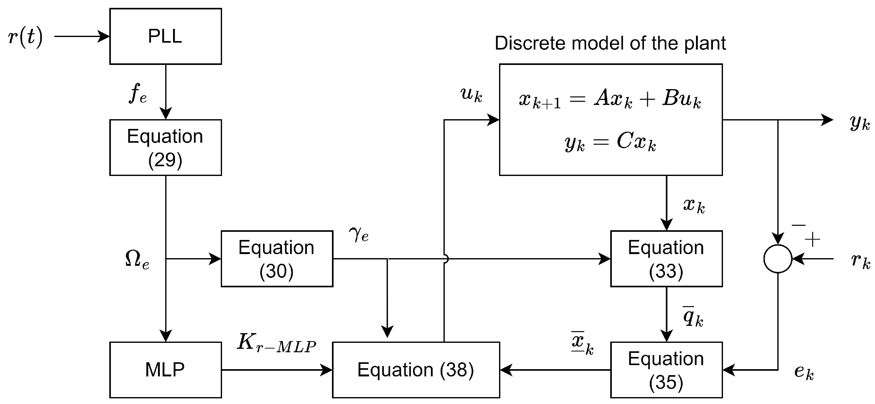
Figure 1. Structure of the proposed resonant controller.
Energies 17 02801 g001
Figure 2. Schematic of the plant used in the tests.
Energies 17 02801 g002
Figure 3. Experimental setup.
Energies 17 02801 g003
Figure 4. Elements of the gain matrix K r with respect to Ω , used in the training of the MLP.
Energies 17 02801 g004
Figure 5. Experimental results for Test 1.
Energies 17 02801 g005
Figure 6. Experimental results for Test 2.
Energies 17 02801 g006
Figure 7. Comparison between controllers. (a) Frequency curve used in the test. (b) Proposed approach. (c) The resonant controller that operates at a fixed frequency of 55 Hz. (d) Proportional quasi-resonant controller.
Energies 17 02801 g007
Table 1. Summary of the results of the tests.
Test NumberMean Square Error (MSE)Settling Time (s)
Test 1 3.21 × 10 4 0.006
Test 2 1.39 × 10 4 0.007
Table 2. Comparison between the controllers.
TestMean Square Error (MSE)
The proposed approach 9.71 × 10 5
The resonant controller operating with fixed frequency 1.15 × 10 4
The proportional quasi-resonant controller 2.30 × 10 3
Disclaimer/Publisher’s Note: The statements, opinions and data contained in all publications are solely those of the individual author(s) and contributor(s) and not of MDPI and/or the editor(s). MDPI and/or the editor(s) disclaim responsibility for any injury to people or property resulting from any ideas, methods, instructions or products referred to in the content.