Article

Numerically Investigating the Energy-Harvesting Performance of an Oscillating Flat Plate with Leading and Trailing Flaps

School of Mechanical Engineering, Kyungpook National University, Daegu 41566, Republic of Korea
*
Author to whom correspondence should be addressed.
Energies 2024, 17(12), 3010; https://doi.org/10.3390/en17123010
Submission received: 24 May 2024 / Revised: 15 June 2024 / Accepted: 15 June 2024 / Published: 18 June 2024

Abstract

:
This study investigates the power generation capability of an oscillating wing energy harvester equipped with two actively controlled flaps positioned at the leading and trailing flaps of the wing. Various parameters, including flap lengths and pitch angles for the leading flap and trailing flap, are explored through numerical simulations. The length of the main wing body ranges from 40% to 65% of the chord length, c, while the leading and trailing flaps vary accordingly, summing up to the total length of the flat plate c = 100%. The pitch angles of the two flaps are adjusted within predefined limits. The pitch angle for the leading flap varies between 25° and 55°, while the trailing flap’s angle ranges from 10° to 40° across 298 different simulation scenarios. The results indicate that employing both leading and trailing flaps enhances the power output compared to a wing with a single flap configuration. The trailing flap deflects the incoming fluid more vertically, while the leading flap increases pressure difference across the surface of the main wing body, synergistically improving overall performance. The power output occurs at a specific length percentage: a leading flap of 30%, a main wing body of 50%, and a trailing flap of 20%, with pitch angles of 50°, 85°, and 30°, respectively, increasing the output power increments by 4.39% compared to a wing with a leading flap, 4.92% compared to a wing with a trailing flap, and 28.24% compared to a single flat plate. The highest efficiency for the specified length percentages is 40.37%.

1. Introduction

The worldwide focus on sustainable and clean energy forms, including photovoltaic, wind, and hydroelectric, plays a critical role in environmental preservation, improving the quality of life for people and advancing the sustainable energy industry [1,2]. Moving from conventional energy sources like coal, oil, and natural gas to renewable alternatives is driving innovation in the energy sector. Among these technologies, oscillating foil systems stand out as a noteworthy option because of their environmentally friendly ability to efficiently convert the kinetic energy of natural water and air flows into usable power [3,4]. While the investigation of energy harvesting via oscillating hydro/aerodynamic mechanisms is a comparatively recent area of research, the concept of employing flapping motions for energy generation was first proposed in 1972 by [5], with its underlying principles established in 1981 by [6]. Their studies focused on wings oscillating harmonically, which combine rotational and vertical movements to harness wind power and realize performance on par with traditional wind turbines. Following these initial studies, comprehensive research has emerged, aimed at refining the energy capture potential of flapping foils. This research has delved into the optimization of motion parameters [7], examined the influence of geometric and viscous variables [8], and explored various flow control techniques [9,10,11,12,13]. Recently, there has been growing interest in the potential of oscillating foils for energy harvesting. Empirical and computational analyses conducted on a NACA0012 foil utilizing a transient panel approach indicated that ideal plunging amplitude and frequency can lead to an energy-harvesting effectiveness of as much as 30% [14]. An extensive parametric evaluation indicated that increasing the rotation amplitude, while keeping the vertical motion conditions constant, can shift the system from power consumption to power generation [15]. A study using FLUENT on a NACA0015 airfoil demonstrated that adjusting the pitching motion within specific frequency and amplitude parameters achieved a peak efficiency of 34%, demonstrating that it is more efficient than vertical motion alone in enhancing power extraction efficiency [16]. Recent progress in piezoelectric power generation has led to highly efficient configurations, exemplified by the U-shaped energy collector [17] and the partially submerged model [18]. A different study showed that the performance of flapping foil power harvesting is affected by factors such as foil movement dynamics, system configuration, flow mechanics, and motion path [19,20]. The relationship between the performance of oscillating foil power harvesters and wake stability was highlighted in recent studies [21].
Researchers have explored tandem arrangements to improve the energy extraction performance of oscillating wing energy harvesters. Studies have shown that the upstream foil in a tandem configuration extracts energy consistently, regardless of the inter-foil spacing, whereas the downstream foil exhibits periodic variations in energy extraction as the separation increases, even though the motion phase shift remains constant [22]. Numerical analysis revealed that an innovative tandem airfoil arrangement oscillating inside a convergent duct significantly boosts energy capture, attributed to boundary constraint effects [23]. A different investigation observed that modifying the vertical distance in tandem or parallel-arranged oscillating wings is able to significantly improve energy capture, resulting in an efficiency improvement of 23%. This underscores the importance of spatial optimization [24]. In addition, the idea of a tandem hydrodynamic foil tidal system was presented, offering advantages in terms of density and cost-effectiveness [25].
Hydrokinetic energy offers a significant potential for dependable power generation. Several studies have investigated the impact of angle of attack changes on the propulsion efficiency of oscillating foils in water-based environments, providing an in-depth examination of the fluid dynamics that advance our knowledge of nature-inspired propulsion systems [26]. Studies were conducted on ideal propulsion patterns for miniature aerial drones and autonomous submersibles, highlighting the relationship between changes in attack angle and propulsion performance [27]. Further similar studies on oscillating foil dynamics in fluids have demonstrated the influence of the attack angle on propulsion performance, being vital to the design as well as the optimization of thrust mechanisms for miniature aerial drones and autonomous submersibles [28]. In addition, research on flapping-foil energy harvesters has explored various deflector designs to boost power output. These studies emphasize the importance of the attack angle and the incoming flow deflector placement for maximizing power generation efficiency [29]. An analysis has been conducted on how density-stratified flow affects energy extraction efficiency, particularly focusing on the amplitude of pitching movements [30].
Studies have demonstrated that combining pitching and heaving motions can significantly improve energy extraction performance. Previous studies have investigated the impact of foil paths and placements, highlighting favorable wake interactions to enhance effectiveness [31]. The power extraction performance of an oscillating hydrofoil was assessed across three different movements: left swing, right swing, and linear. The left-swing motion was found to be more effective at extracting power compared to the right-swing motion and linear trajectories [32]. Non-sinusoidal trajectories have been demonstrated to outperform sinusoidal motions in terms of power output [33,34]. Notably, research on sinusoidal motions identified an optimal efficiency surpassing 33% for a flapping foil [35]. However, investigations into non-sinusoidal motion indicate a slightly lower optimal efficiency of 32% with the same parameters [36]. Furthermore, semi-active oscillating foils with cosine-based pitching movements enhance the performance of the power collector [37]. A hybrid motion that combines non-sine-based and sinusoidal trajectories resulted in a 16.0% increase in power output compared to sinusoidal motion for oscillating flat plate energy harvesters, as reported by [38].
Energy harvesting from flapping-foil systems is achievable via two main flow control approaches: passive and active control [39]. These strategies differ depending on whether additional energy is required in the fluid domain. Passive control strategies improve power harvesting by implementing straightforward adjustments directly to the airfoil surface, eliminating the need for extra power input. It was discovered that vortex motion was enhanced by flexible deformation on the foil’s low-pressure side, improving the lifting force and increasing power extraction by altering the foil’s pressure distribution [40]. This study explores the morphological influence of a scallop shell on the performance of a flapping-type tidal stream generator, investigating an alternative approach to enhance the hydrodynamic efficiency of tidal energy converters [41]. Incorporating a Gurney flap was found to increase vortex formation at the rear edge and amplify the pressure differential along the foil, boosting heaving force and resulting in 21% improvements in energy-harvesting efficiency [42,43]. The exploration of fully passive flapping foils in free surface flow aimed to identify optimal submergence depths and the effects of monochromatic waves [44]. A responsive control mechanism has been designed to adjust the attack angle, with the goal of increasing lift force and improving overall power output [45]. It was discovered that using a shroud can increase the power extraction efficiency of an oscillating foil by 35.8% compared to its unshrouded version [46]. A study revealed that attaching flat plates to the trailing edge of flapping foils influences energy extraction, improving efficiency for both flexible and rigid plates [47].
In contrast to passive techniques, active control methods, including circulation control [48] and plasma actuators [49], outperform passive methods. In the aerospace industry, flaps are frequently utilized within lifting mechanisms due to their straightforward design, durability, and high efficiency [50,51]. A fully deformable flapping foil increased the power output by 2% compared to a traditional airfoil [52]. Flaps are employed to enhance the power efficiency of oscillating energy collectors. A study investigated the power extraction in an oscillating energy collector incorporating a trailing edge that was 20% 20% relative to the overall length and found that by optimizing the flap pitch angle and wing pitch angle to 35° and 70°, respectively, there was an 11% increase in power compared with an oscillating wing without a flap [53]. A study investigating the impact of extending the trailing edge flap on a flapping wing revealed an increase of 26.9% in power and a 21% improvement in performance at a 60% flap length [54]. Similar success was achieved with leading-edge flaps, with a study finding a configuration that boosted power by 29.9% and efficiency by 23% [55]. Extensive studies have been conducted on the use of flaps in applications involving single blades and vertical-axis wind turbines [56,57,58]. The empirical evidence shows that specific structural adjustments can significantly enhance energy-harvesting performance [59]. Similarly, a study explores the enhancement of vibrational energies through modifications in flow dynamics [60]. Lastly, these studies examine how dynamic adjustments to wing configurations can affect energy extraction by modifying lift and drag forces, as highlighted by [10,61].
Previous studies focused on flat plates without any flaps or a flat plate with one flap. They have shown that incorporating either a leading flap or a trailing flap significantly enhances the performance of energy harvesters. This study explores a novel approach by simultaneously integrating both leading and trailing flaps to an oscillating flat plate-based energy harvester to enhance its output performance. A numerical analysis was conducted to investigate the effect of varied leading and trailing flap pitch angles and the effect of the lengths of the two flaps on output power. This study chose a main wing body pitch angle of 85°, as it was found to produce more output power compared to pitch angles of 90° and 80°. This comprehensive investigation revealed the importance of an oscillating flat plate with two flaps to improve energy-harvesting performance in this system.

2. Numerical Methodology

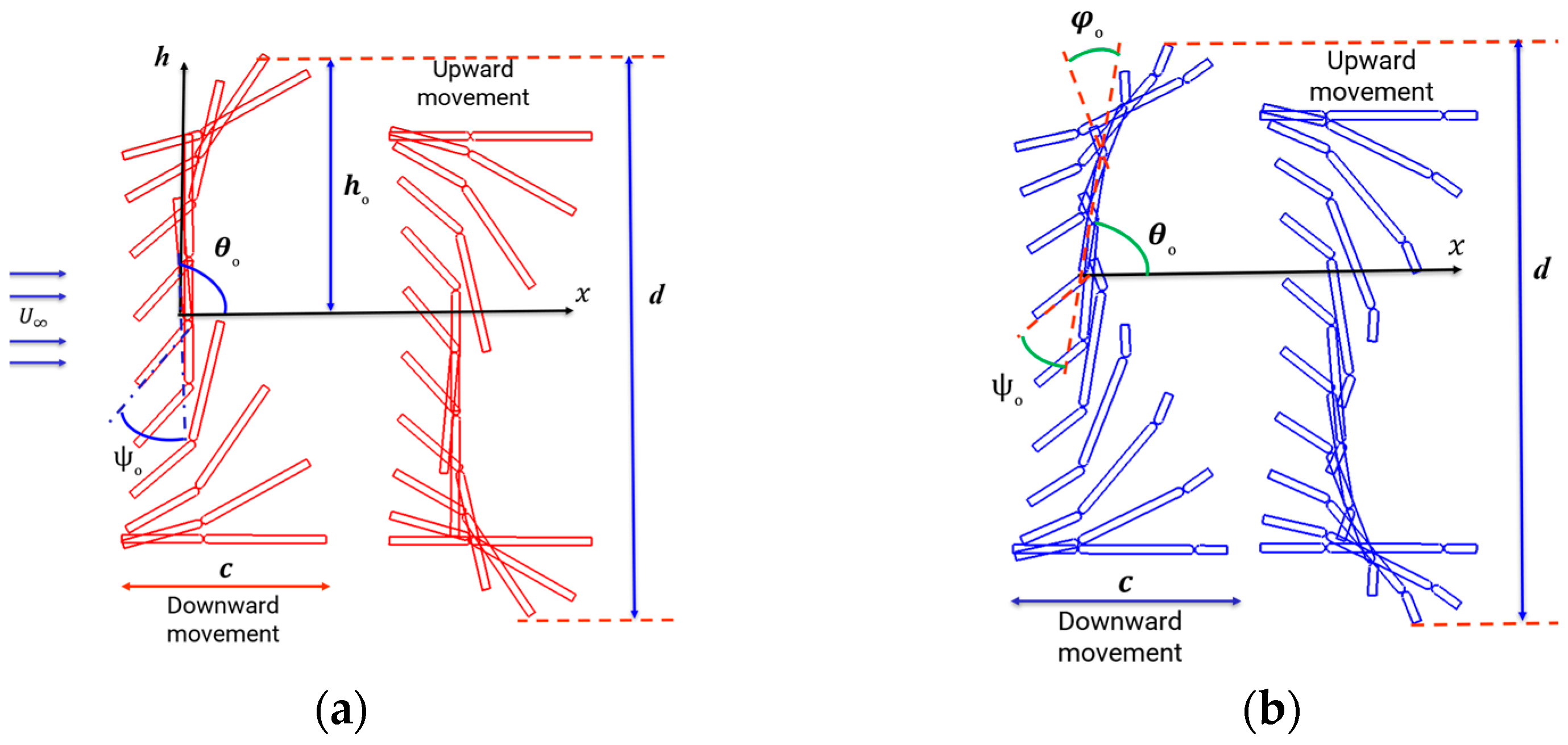
The flat, rectangular plate offers advantages over a profiled airfoil [62]. This study uses a two-dimensional oscillating flat plate with a span of c, as shown in Figure 1. Figure 1a shows a flat plate with a leading flap, Figure 1b shows a flat plate with a trailing flap, and Figure 1c shows the oscillating flat plate with a leading and a trailing flap. The oscillating flat plate model with leading and trailing flaps maintains identical physical characteristics (e.g., the total chord length, c = 1.0, and the thickness, t w , is 4% of c), at reduced frequencies f = 0.14 and heaving amplitudes, h 0 = c, which provide the maximum power and performance [62]. Variables such as the lengths of the flaps and their pitch angles are varied. There is a gap between the wing and the two flaps that equals 0.2% of the chord length of the flat plate, while the connection between the main wing body and the two flaps has a radius that is half the thickness of the plate. Figure 2 shows the oscillating kinematics in two scenarios: a flat plate with a leading flap, as shown in Figure 2a, and Figure 2b shows the oscillating flat plate with leading and trailing flaps. The pivot point, 0.333c from the front edge, coincides along the centerline of the oscillating plate. The incoming fluid velocity is denoted by U . This study investigates the effect of affixing both leading and trailing flaps to the main wing body by comparing its power generation capacity to that of wings equipped solely with a leading flap or a trailing flap. The oscillating plate experiences vertical movements, expressed as h(t) in Equation (1). In this context, h(t) represents the instantaneous heaving motion, and h 0 is the maximum heaving motion of the wing. Here, ω = 2πf, where f is the angular flapping frequency, t denotes time, and ∅ indicates the phase difference between heave and pitch motions.
h ( t ) = h 0   sin   ( ω   t + )
The pitch motion of the main wing body, (θ), the leading flap, ( ψ ), and the trailing flap, ( φ ), is governed by sinusoidal motion [62] in Equations (2), (3), and (4), respectively, where θ denotes the pitch angle of the main wing body.
θ ( t ) = θ O   sin ( ω   t )
ψ ( t ) = ψ o   sin ( ω   t )
φ ( t ) = φ o   sin ( ω   t )
R e = ρ U c μ
Here, ρ is the fluid density, U signifies the free stream velocity, c is the length of the chord, and μ denotes the dynamic viscosity of the fluid. The term reduced frequency f* is defined as follows:
f = f c U
A 2D transient condition numerical simulation was performed at R e = 500,000 to evaluate the performance of the energy harvester.
To calculate the energy output, the average power ( P ¯ ) is determined by integrating the instantaneous power (P) across one cycle as follows:
P = Y t d h ( t ) d t + M t d θ ( t ) d t
P ¯ = 1 T 0 T P d t ,
Y(t) represents the y-direction force, M(t) denotes the pitching moment, and T is the time period.
C p t = P 1 2 ρ U 3 c = 2 ρ U 3 c [ Y t d h ( t ) d t + M t d θ ( t ) d t ]
C p t = C p l + C p m = 1 U [ C L t d h ( t ) d t + C M t d θ ( t ) d t ]
C L (t) indicates the instantaneous pushing coefficient and C M (t) refers to the instantaneous moment coefficient as follows:
C L ( t ) = Y ( t ) / 1 2 ρ U 2 c
C M ( t ) = M ( t ) / 1 2 ρ U 2 c
The average power coefficient ( C p t ¯ ) is determined by integrating the instantaneous C p t values throughout the cycle.
C p t ¯ = 1 T 0 T C p t d t = P ¯ / ( 1 2 ρ U 3 c )
or
C p t ¯ = C p l ¯ + C p m ¯ = 1 T U [ 0 T C L t d h t d t d t + 0 T C M t d θ t d t d t ]
Equations (10) and (14) show that C p l and C p l ¯ correspond to energy extraction based on pushing forces, whereas C p m and C p m ¯ indicate the contributions from moment-based forces. Considering the combined effects of the main wing body and the two flaps, the forces, moments, and power generated by all components were summed. The calculation of the moment power for the flap included accounting for the relative angular motion between the main wing body of the flat plate and the flap. The efficiency of power generation for the oscillating flat plate energy harvester, denoted by η, is calculated using Equation (15) as follows:
η = C p t c d
Here, d represents the maximum vertical spacing of the oscillating foil.
This study uses the overset mesh method as its approach effectively simulates multibody structures, complex geometries, and big body movements [63]. The overset mesh method and the Reynolds-averaged Navier–Stokes flow equations have been derived using version 21 R1 of the Fluent software [64]. The model used the finite volume method along with a pressure-based solver, with the fundamental equations specified in Equations (16) and (17).
u i x i = 0
t ( ρ u i ) + x j ( ρ u i u j ) = P x i + x j   ( μ ( u i x j + u j x i 2 3   δ i j   u l x l ) + x j   ( ρ   u i u j ¯ ) )
u i and u j denote the velocity components. In Equation (17), the term for Reynolds stress − ρ u i u j ¯ is derived using the turbulence model (k − ω SST), which serves as the simulation method employed in this study [63,65]. Spatial discretization of pressure, momentum, and eddy viscosity is achieved using the second-order upwind method. The motion of the flat plate was defined through user-defined functions (UDFs), and the mesh motion was handled by employing the dynamic mesh method.
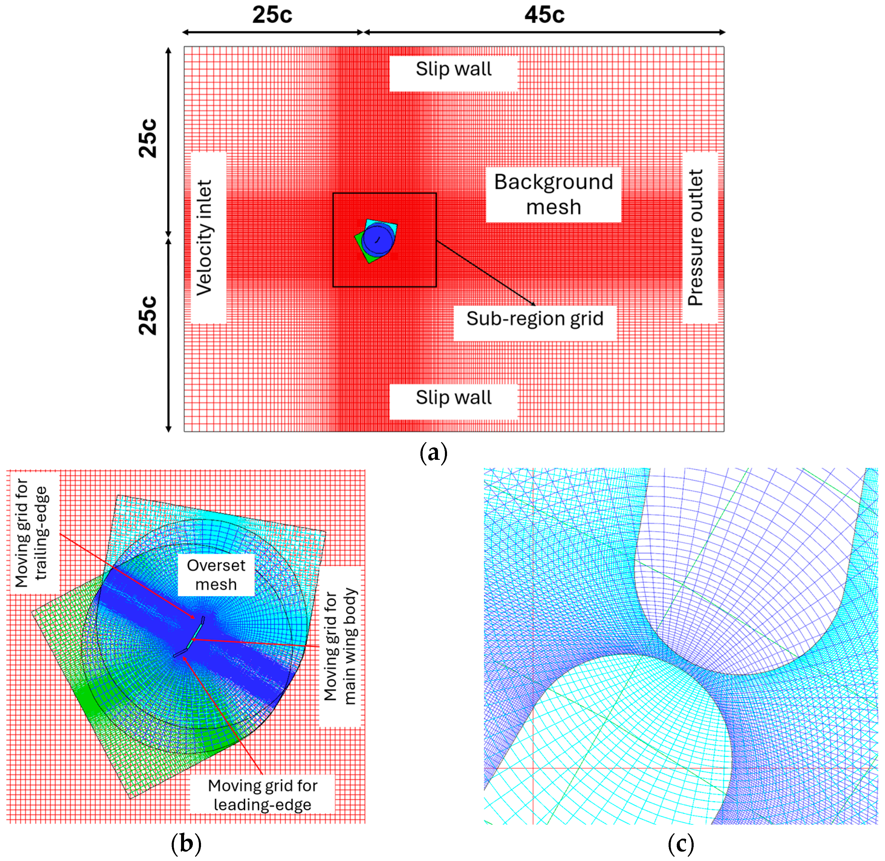
Figure 3 illustrates the rectangular computing area, mesh, sub-region grids, and boundary conditions used in the simulation. A domain independence study determined the optimal computational domain dimensions to be a length, l, ranging from −25c to 45c, and a breadth, b, from −25c to 25c. Enlarging the domain beyond these dimensions did not influence the results. The pressure outlet boundary was set at 45c, and the upper and lower boundaries were assigned a slip boundary condition, as shown in Figure 3a.
Distinct sub-grids (moving grids) were employed for the main wing body, the leading flap, and the trailing flap, as depicted in Figure 3b. Figure 3c presents a zoomed-in view of the main wing body and the trailing edge. The movable grid configurations for the main wing body were structured into elliptical grids with a diameter of 4c, while the grids for the leading and trailing flaps were organized into oval grids of the same diameter. The analysis presented reflects data collected from the seventh stable periodic cycle.
To evaluate the accuracy and reliability of the numerical simulations, studies focusing on grid and time independence were carried out by varying the grid resolution and time step size. Three different levels of mesh density were used: coarse, medium, and fine grids. The impacts of mesh resolution and time steps on the calculated C ¯ P t are presented in Table 1. For the time step independence study, a medium grid came into use over time steps of 500, 2000, and 4000 per cycle. Table 1 shows the output power coefficient and its relative variation. The results indicate that the medium mesh resolution offers adequate spatial accuracy and shows minimal variation across different time steps.
To validate the numerical model and mesh, this simulation compared results with those from [53,62], showing good agreement, as illustrated in Figure 4. To balance accuracy with computing time, this study has selected the medium mesh with 2000 time steps per cycle to ensure both precision and reliability.

3. Results and Discussion

This study examined the power extraction capabilities of an oscillating flat plate with a leading flap and a trailing flap during combined heaving and pitching motions. The movements are analyzed under specific conditions: a pivot point at x p = 0.333c, a phase angle of 90°, a reduced frequency of f = 0.14, and a heave amplitude to chord ratio of h 0 /c = 1.0, which show the optimum performance as mentioned in [62]. This study investigated the broader effectiveness of this configuration under various motion parameters, including the pitch angles and the length percentages of both flaps.

3.1. Effect of the Leading Flap’s Pitch Angles on an Oscillating Flat Plate with Two Flaps

In this section, the energy-harvesting performance of a main wing body equipped with leading and trailing flaps is compared to that of a wing with a leading flap, a trailing flap, and a flat plate without any flap. Table 2 shows the length percentages and pitch angles for a wing without any flaps, as well as for the wing equipped with either leading or trailing flaps. The output power C p t = 1.183 for the wing with a leading flap is higher than the output power C p t = 1.177 for the wing with a trailing flap, showing the importance of the leading flap. These specific percentages with their pitch angles for a wing with a flap were selected in this study because they yield the most efficient energy extraction, as noted by [54,55], and for a wing without any flaps, as noted by [62].
The calculations in Table 3 and Table 4 have selected the following length percentages for the oscillating flat plate with a leading and a trailing flap: the leading flap at 30% (L30), the main wing body at 55% (W55), and the trailing flap at 15% (T15) of c. This configuration was chosen for its good power extraction performance.
Table 3 shows the calculated results for the main wing body pitch angle, θ O = 85°, the trailing flap pitch angle, φ o = 30°, and the pitch angle of the leading flap, ψ o , which varies between 25° and 50° in 5° increments. The best case in Table 3—consisting of a 30% leading flap length, a 55% main wing body, and a 15% trailing flap length—yields a modest output power coefficient C p t of 1.225, representing a 27.20% increase in output power compared to a single wing without any flaps, which has a C p t 0.963. Additionally, it shows a 21.44% increase in efficiency compared to the single wing without any flaps, which has an efficiency of 37.30%, as noted in [54].
Through more than 298 cases, the calculated results of the output power with different length percentages of the leading flap, main wing body, and trailing flap show that the best pitch angle of the main wing body is θ O = 85°. In this specific length percentage, the total power coefficient, C p t , at the leading flap pitch angle, 45°, the trailing flap pitch angle, 30°, and the different main wing body pitch angles ( θ O = 90°, θ O = 85°, and θ O = 80°) were calculated as 1.200, 1.225, and 1.086, respectively. Therefore, the pitch angle of the main wing body, θ O = 85°, was used as it consistently delivered higher output power compared to other pitch angles.
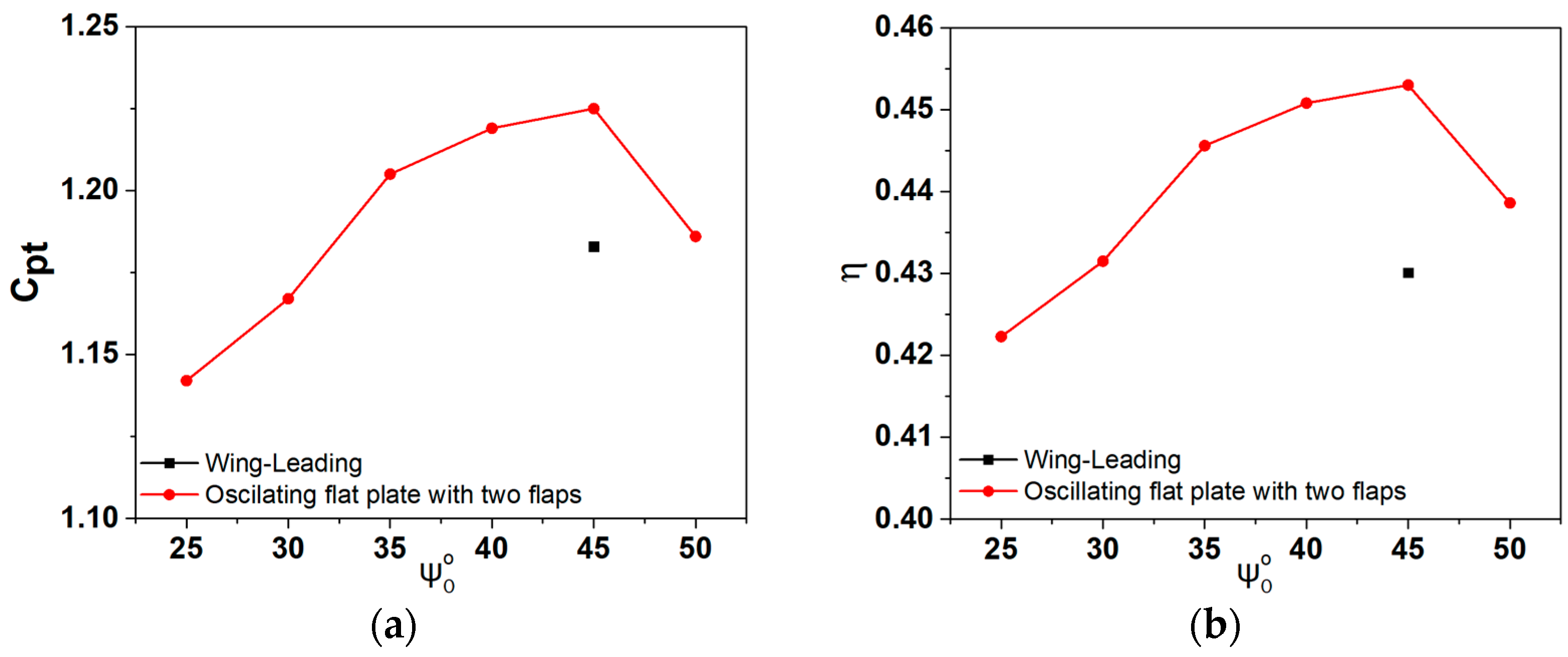
Figure 5 shows the output power coefficient and efficiency for an oscillating flat plate with two flaps compared to a wing with a leading flap. The length percentages and the pitch angles for the wing with the leading flap are shown in Table 2. This wing with a leading flap, marked by the black point in Figure 5a,b, is the optimum case study as mentioned in [55]. The oscillating flat plate with two flaps (L30, W55, and T15) shows a notable performance, achieving an output power C p t of 1.225 and an efficiency η of 45.30%, which surpass the corresponding values of 1.183 in C p t and 43.01% in η observed for the wing with a leading flap. Under the same conditions previously described, the oscillating flat plate with two flaps (L30, W55, and T15) shows increased output power, with a C p t value of 1.225, compared to a C p t of 0.963 for a single flat plate. Furthermore, it shows a 21.44% increase in efficiency compared to the single wing without flaps, which has an efficiency of 37.30% as mentioned in [54].
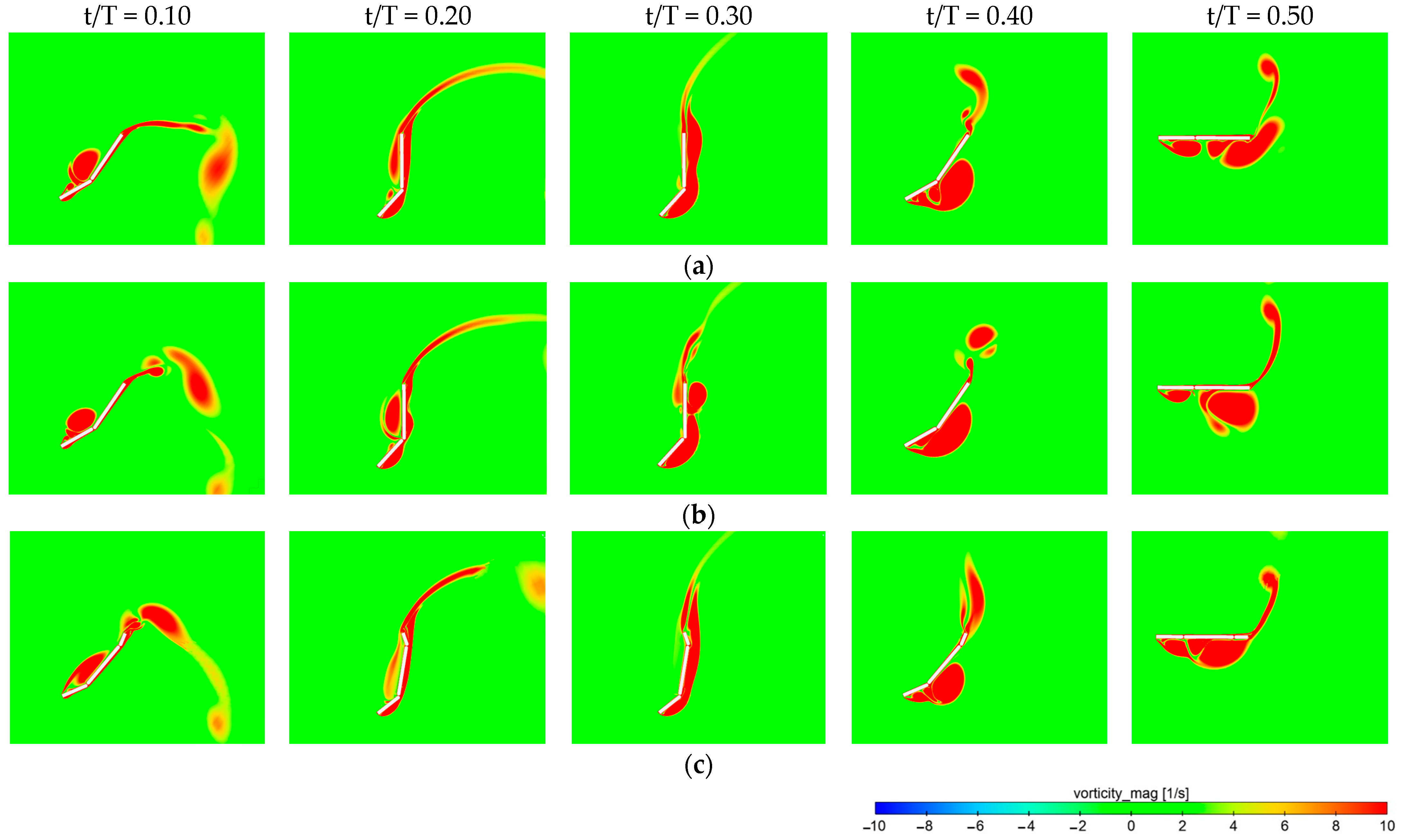
Figure 6 shows vorticity plots around the surface of the oscillating flat plate. Vortex patterns depicted in Figure 6a,b exhibit a notable resemblance to each other, underscoring the similarity in aerodynamic flow behaviors between the two configurations of a wing with a leading flap or a wing with a trailing flap. Meanwhile, Figure 6c shows vorticity plots of the oscillating flat plate equipped with both a leading and a trailing flap. Notably, this configuration shows a reduced area of flow separation when compared to the wings with either a leading or a trailing flap alone, particularly during the time period 0.2 < t/T < 0.3.
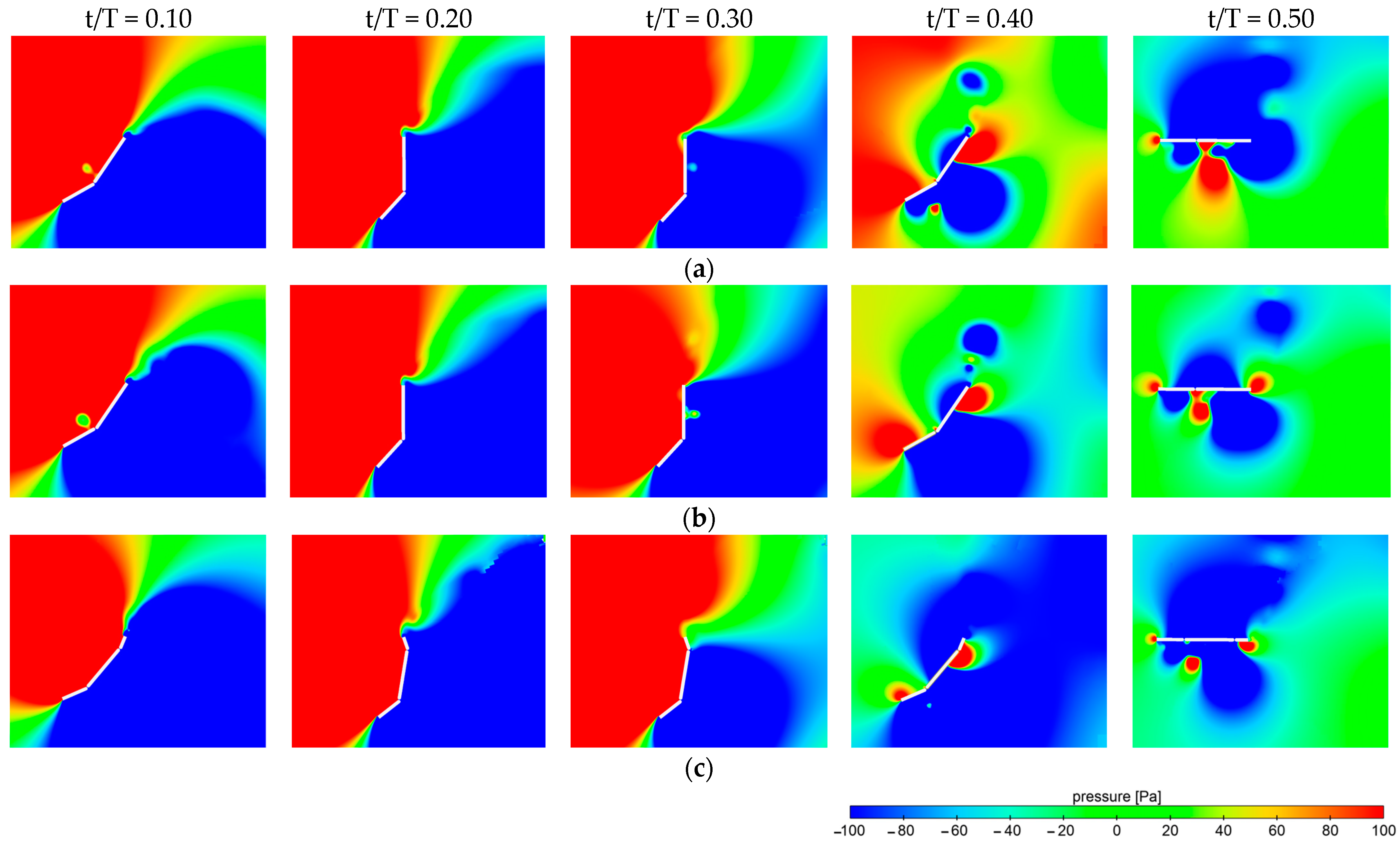
Figure 7 shows the pressure contour around the surface of the oscillating flat plates. The windward side of the flat plates exhibited high pressure due to the incoming flow. The analysis of the pressure contours for the wing with a leading flap and the wing with a trailing flap, as shown in Figure 7a,b, respectively, reveals similar patterns. Moreover, the calculated results for power extraction from these two configurations also exhibit similar values, indicating consistency in their aerodynamic behaviors. However, the pressure contour of the oscillating flat plate with both a leading and a trailing flap distinctly differs from those of the single flap configurations, as shown in Figure 7c. This divergence in the pressure distribution coefficients can be shown in Figure 8.
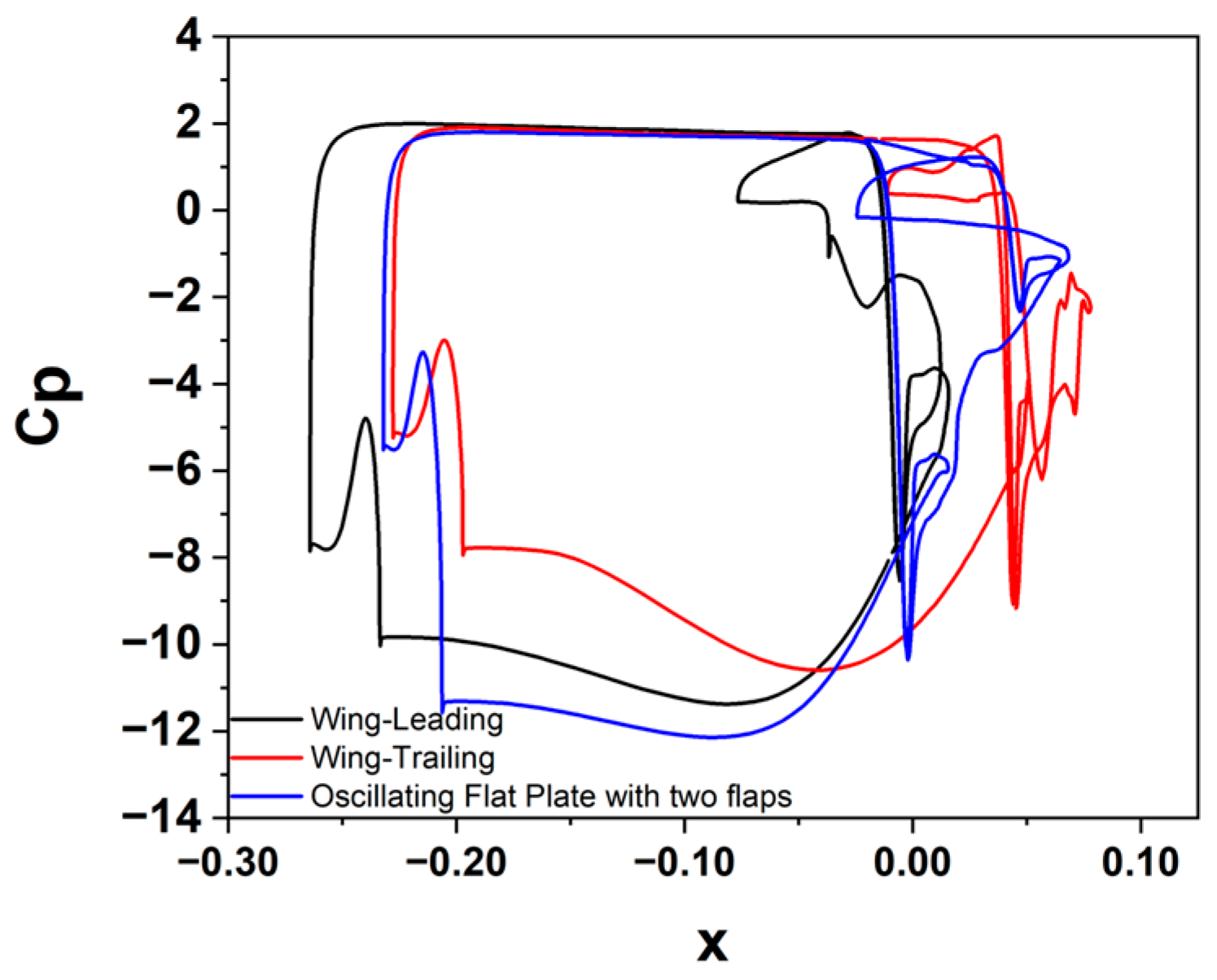
Figure 8 shows the pressure coefficient on the surface of the flat plate during the heaving motion for three different case studies at t/T = 0.25. The wing with a leading flap begins its projected length earlier than other cases, yet the overall projection length aligns closely with the wing with a trailing flap case. The pressure difference between the top and bottom surfaces is similar for the single flap configurations. However, the pressure difference in the case of an oscillating flat plate equipped with both a leading and a trailing flap is notably greater than in the single flap configurations.

3.2. Effect of the Trailing Flap’s Pitch Angles on an Oscillating Flat Plate with Two Flaps

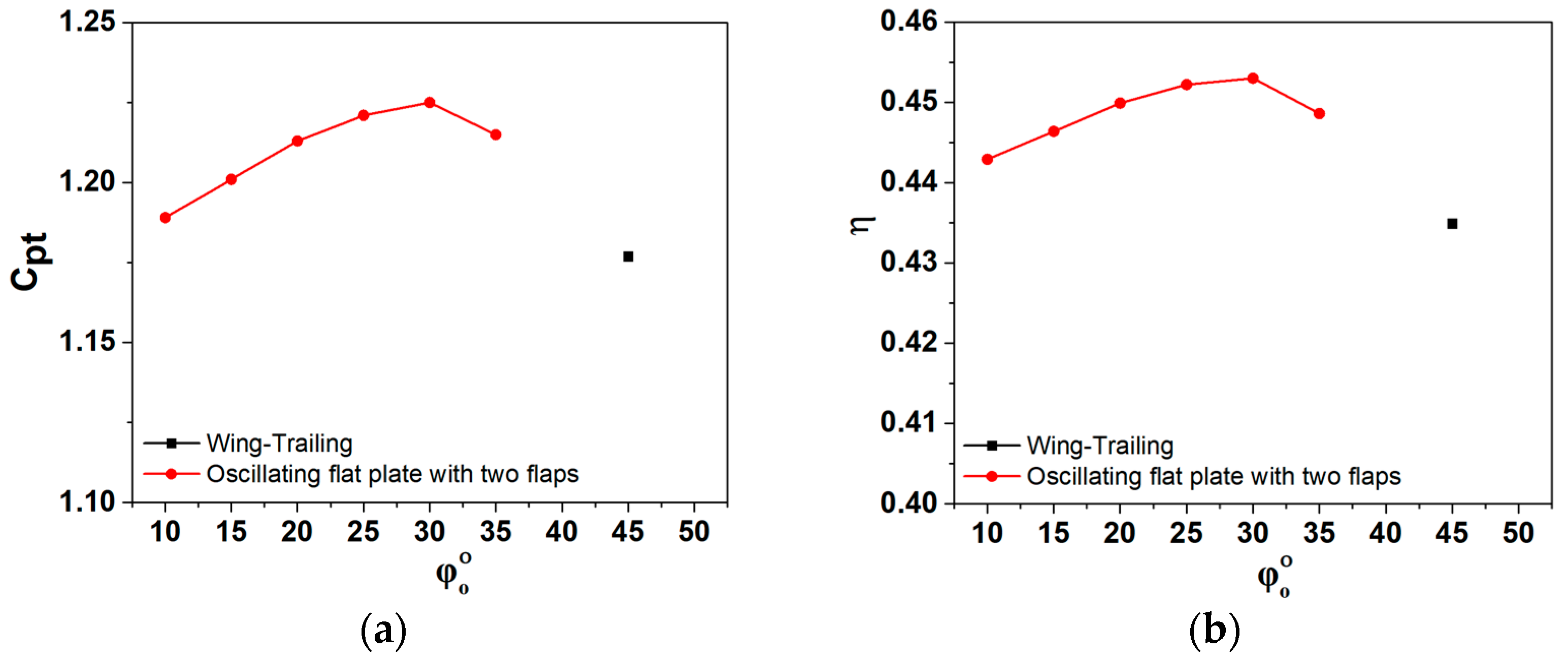
Table 4 presents the values of the calculated results for θ O = 85°, ψ o = 45°, φ o varying from 10° to 35° in 5° increments. The C p t shows a notable increase as φ o increases from 10° to 35° but decreases when φ o exceeds 35°. The C p t for the oscillating flat plate with two flaps shows an enhancement of 3.55% compared to a wing configuration with only a leading flap. The oscillating flat plate with two flaps shows a gradual increase in efficiency, η, as the trailing flap pitch angle, φ o , rises from 10° to 30°. Starting at 44.29% at a 10° pitch angle and peaking at 45.30% at a 30° pitch angle, this shows a notable increase in the performance. Although the efficiency slightly decreases to 44.86% at 35°, it still remains higher than that of the wing with a leading flap.
Figure 9 shows the output power coefficients and efficiency for an oscillating flat plate with two flaps compared to a wing with a trailing flap. The length percentages and the pitch angles for the wing with a trailing flap are shown in Table 2. The wing with a trailing flap, marked by the black point in Figure 9a,b, is the optimum case study as mentioned in [54]. The oscillating flat plate with two flaps shows a notable performance, achieving an output power C p t of 1.225 and an efficiency η of 45.30%, which outperforms the corresponding values of 1.177 in C p t and 43.01% in η observed for the wing with a trailing flap.

3.3. Effect of Flap Lengths on an Oscillating Flat Plate with Two Flaps

This section investigates the impact of varying the lengths of the leading and trailing flaps on the energy harvester’s power output, utilizing two different main wing body length percentages, 50% and 55%, and exploring modifications in the trailing flap lengths at 10%, 15%, and 20%. Additionally, adjustments are made to the leading flap lengths to ensure that the sum of the leading flap, main wing body, and trailing flap segments equals the total length c = 100%. Throughout this analysis, the angles ψ o = 45°, θ O = 85°, and φ o = 30° are used.
Table 5 shows the calculated results of C p l , C p m , and C p t for main wing body lengths of 50% and 55%, alongside variations in the lengths of leading and trailing flaps, all maintained at constant pitch angles of ψ o = 45°, θ O = 85°, and φ o = 30°. The calculated results of the studied cases reveal that the best C pt values are achieved with leading and trailing flap lengths set at 30% and 15% of c. The length percentage of a 55% main wing body shows the highest efficiency of 45.30% at a 30% leading flap length and a 15% trailing flap length.
Table 6 shows the calculated power extraction coefficients and efficiencies for main wing body lengths of 50%, 55%, and 60%, along with variations in the lengths of leading and trailing flaps, all maintained at constant pitch angles of ψ o = 50°, θ O = 85°, and φ o = 30°. Compared to the previous case with length percentages of L30, W55, and T15, the current length percentages of L30, W50, and T20, along with an increase in the leading flap pitch angle ( ψ o ) from 45° to 50°, result in an increase in output power from C p t = 1.225 to C p t = 1.235 and efficiency from η = 45.30% to η = 45.37%.

3.4. Effect of the Combination of Lengths and Pitch Angles on an Oscillating Flat Plate with Two Flaps

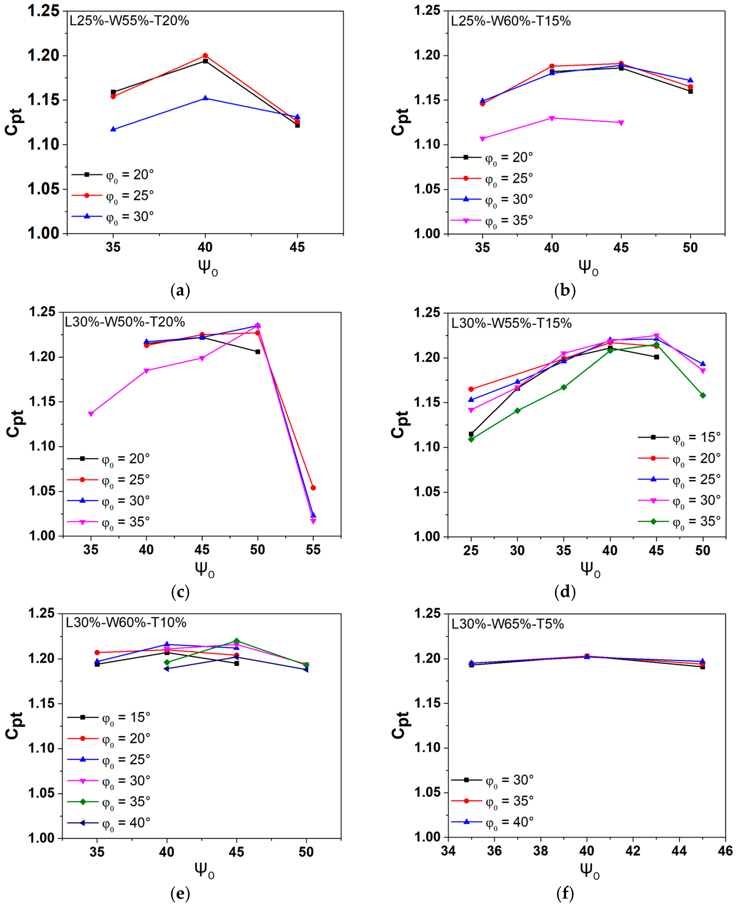
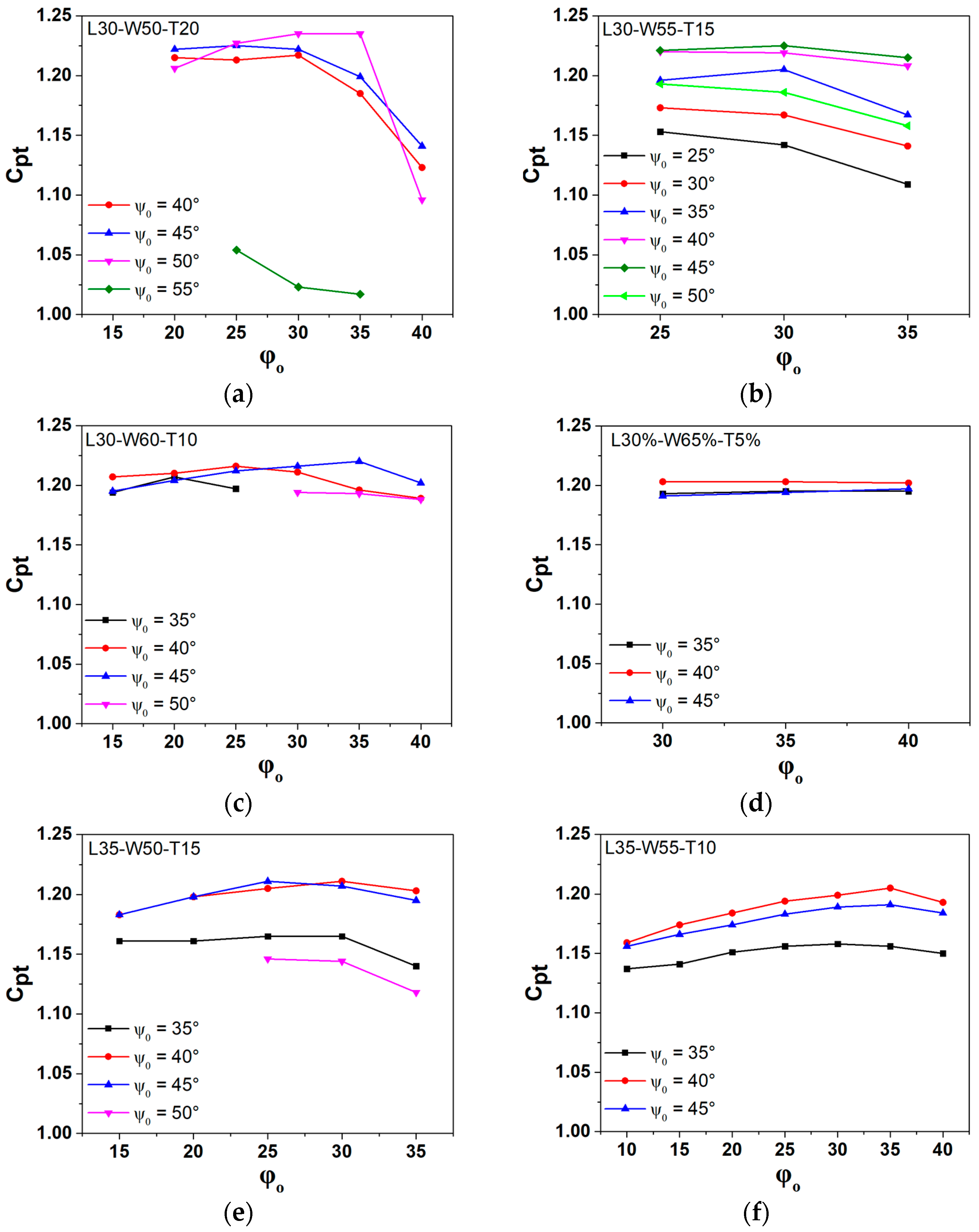
Figure 10a–f show the combined effects of changes in the leading flap length percentages (25%, 30%, and 35% of c) and the pitch angles of the leading flap, ψ o , at the pitch angle of the main wing body, θ O = 85°, and various trailing flap pitch angles, φ o .
Figure 10a,b show the output power for the length percentages (L25, W55, T20) and (L25, W60, T15), respectively, with the leading flap length percentages at 25% of c. The calculated results indicate that the output power, C p t , increases at a leading flap pitch angle ψ o of 40° across various trailing flap pitch angles φ o ranging from 20° to 30°. An enhancement in the output power, C p t , is achieved when the trailing flap length percentages increase from T15 in the configuration (L25, W60, T15) to T20 in the configuration (L25, W55, T20). This improvement is observed at a trailing flap pitch angle of 25° and a leading flap pitch angle of ψ o = 40°. Figure 10b shows that for the length percentages of L25, W60, and T15, decreasing the trailing flap length percentage from T20 to T15, while maintaining the leading flap length percentage at L25, results in a slight decrease in the output power. Figure 10c–f show the following cases: L30, W50, and T20; L30, W55, and T15; L30, W60, and T10; and (L30, W65, and T5), all with the same leading flap length percentage at 30% of c. The calculated results show that increasing the leading flap length percentage to L30 enhances the output power compared to the leading flap length percentage of L25. For the same leading flap length percentages of L30, decreasing the trailing flap length percentage from 20% to 15%, 10%, and 5% resulted in slightly lower output power C pt values of 1.227, 1.225, 1.220, and 1.203, respectively.
Figure 10g,h show the output power for the leading flap length percentage of L35. For the length percentages of L35, W50, and T15 and L35, W55, and T10, the output power C p t values are 1.211, and 1.205, respectively. The calculated results show that increasing the leading flap length percentage to L35 enhances the output power compared to the leading flap length percentage of L25. However, the output power for L35 is slightly lower than that for L30, showing that excessive increases in the leading flap length percentage can lead to a slight decrease in output power. Additionally, the trailing flap pitch angle has a minor effect on the output power, especially for short trailing flap length percentages of T5, and T10, as observed in the following cases: L35, W55, and T10; L30, W60, and T10; and L30, W65, and T5, as shown in Figure 10e,f.
Figure 11 shows the combined effects of variations in the trailing flap length percentages (5%, 10%, 15%, and 20%) and the trailing flap pitch angles, φ o , on the output power at the main wing body pitch angle, θ O = 85°, and various leading flap pitch ψ o angles. Figure 11 shows that the output power is less influenced by the trailing flap pitch angle, φ o , than by the leading flap pitch angle, ψ o .
Figure 11a–d show the output power for the following length percentages: L30, W50, and T20; L30, W55, and T15, L30, W60, and T10; and L30, W65, and T5. In each case, the leading flap length percentage is kept constant at 30%, while the trailing flap length percentage is progressively reduced from 20% to 5%. The calculated results show that reducing the trailing flap length percentage from T20 to T5 leads to a decrease in output power.
Figure 11e,f show the output power for the following length percentages: L35, W50, and T15 and L35, W55, and T10, with a leading flap length percentage of 35%. There is a slight reduction in output power when the leading flap length percentage is 35% compared to 30%.
The calculated results from the previously studied cases indicate that the best performance is typically achieved with a leading flap length percentage of 30% and trailing flap length percentages ranging from 15% to 20% at ψ o values between 40° and 45° and φ o values between 30° and 35°. The best length percentages across all studied cases were achieved with L30–W50–T20 at pitch angles of ψ o = 50°, θ O = 85°, and φ o = 30°, respectively. This configuration maximized power output by 4.92% compared to a wing with a trailing flap and by 28.24% compared to a single flat plate without any flaps.
The leading flap reduces fluid separation under the main wing near the leading edge and increases pressure difference. Additionally, the leading flap extends the projected length in the heaving direction. The trailing flap redirects fluid more vertically, increasing momentum change in the heaving direction for better power output. Combining the leading and trailing flaps enhances performance.

4. Conclusions

This study has provided a comprehensive numerical evaluation of the energy-harvesting capabilities of oscillating flat plate harvesters, which use both leading and trailing flaps. The overset mesh method under unsteady conditions and the k − ꞷ SST turbulence model were used in these simulations. Through more than 298 numerical simulations, various parameters were analyzed, including the length percentages and pitch angles for the leading flap, which ranged from 25% to 40% and 20° to 40°, respectively. For the main wing body, the length percentages spanned from 50% to 65%, with pitch angles between 80° and 90°. Additionally, the trailing flap’s length percentages varied from 5% to 20%, with pitch angles from 5° to 40°. In this study, the best performance was achieved with specific length percentages: a leading flap of 30%, a main wing body of 50%, and a trailing flap of 20% at pitch angles of 50°, 85°, and 30° for the leading flap, main wing body, and trailing flap components, respectively. This case maximized power output by 4.92% compared to a wing with a trailing flap and by 28.24% compared to a single flat plate without any flaps. The efficiency increased by up to 45.37% compared to a wing with a trailing flap. This study highlights the benefits of using an oscillating flat plate with a leading flap and a trailing flap and the effects of the length percentage and pitch angle adjustments of the oscillating flat plates with two flaps. Configurations with flap lengths exhibited a notable improvement in energy extraction, indicating their potential for enhancing the performance of energy harvester systems.

Author Contributions

S.S. and C.-H.S. were responsible for conceptualization; S.S. handled methodology, software, validation, formal analysis, data curation, and original draft preparation. Both S.S. and C.-H.S. participated in investigation and visualization. C.-H.S. provided resources, supervision, project administration, and funding acquisition. All authors have read and agreed to the published version of the manuscript.

Funding

This work received financial support from the National Research Foundation of Korea (NRF) under the Korean government (MSIT) grant number 2022R1F1A1061903.

Data Availability Statement

The data supporting the findings of this study can be obtained from the corresponding author upon request.

Conflicts of Interest

The authors confirm that there are no conflicts of interest associated with this publication.

References

  1. García-Olivares, A.; Solé, J.; Osychenko, O. Transportation in a 100% renewable energy system. Energy Convers. Manag. 2018, 158, 266–285. [Google Scholar] [CrossRef]
  2. Paiva, A.S.S.; Rivera-Castro, M.A.; Andrade, R.F.S. DCCA analysis of renewable and conventional energy prices. Phys. A Stat. Mech. Its Appl. 2018, 490, 1408–1414. [Google Scholar] [CrossRef]
  3. Jones, K.D.; Davids, S.; Platzer, M.F. Oscillating-wing power generator. In Proceedings of the 3rd ASME/JSME Joint Fluids Engineering Conference, San Francisco, CA, USA, 18–23 July 1999; American Society of Mechanical Engineers: New York, NY, USA, 1999. [Google Scholar]
  4. Shimizu, E.; Isogai, K.; Obayashi, S. Multiobjective design study of a flapping wing power generator. J. Fluids Eng. 2008, 130, 021104. [Google Scholar] [CrossRef]
  5. Wu, T.Y.-t. Extraction of flow energy by a wing oscillating in waves. J. Ship Res. 1972, 16, 66–78. [Google Scholar] [CrossRef]
  6. McKinney, W.; DeLaurier, J. Wingmill: An oscillating-wing windmill. J. Energy 1981, 5, 109–115. [Google Scholar] [CrossRef]
  7. Lindsey, K. A Feasibility Study of Oscillating-Wing Power Generators; Naval Postgraduate School: Monterey, CA, USA, 2002. [Google Scholar]
  8. Xie, Y.; Lu, K.; Zhang, D. Investigation on energy extraction performance of an oscillating foil with modified flapping motion. Renew. Energy 2014, 63, 550–557. [Google Scholar] [CrossRef]
  9. Zhu, B.; Han, W.; Sun, X.; Wang, Y.; Cao, Y.; Wu, G.; Huang, D.; Zheng, Z.C. Research on energy extraction characteristics of an adaptive deformation oscillating-wing. J. Renew. Sustain. Energy 2015, 7, 023101. [Google Scholar] [CrossRef]
  10. Rushen, J.; Siala, F.; Totpal, A.D.; Planck, C.J.; Liburdy, J.A. The effects of a passively actuated trailing edge on the aerodynamics of an oscillating wing. In Proceedings of the Fluids Engineering Division Summer Meeting, Chicago, IL, USA, 3–7 August 2014; American Society of Mechanical Engineers: New York, NY, USA, 2014; p. V01BT12A012. [Google Scholar]
  11. Zhu, B.; Xia, P.; Huang, Y.; Zhang, W. Energy extraction properties of a flapping wing with an arc-deformable airfoil. J. Renew. Sustain. Energy 2019, 11, 023302. [Google Scholar] [CrossRef]
  12. Sun, G.; Wang, Y.; Xie, Y.; Ma, P.; Zhang, Y. Hydrodynamic and energy extraction properties of oscillating hydrofoils with a trailing edge flap. Appl. Ocean Res. 2021, 110, 102530. [Google Scholar] [CrossRef]
  13. Drost, K.; Linvog, H.; Apte, S.; Liburdy, J. Low reynolds number flow dynamics of a thin airfoil with an actuated leading edge. In Proceedings of the 41st AIAA Fluid Dynamics Conference and Exhibit, Honolulu, HI, USA, 27–30 June 2011; p. 3904. [Google Scholar]
  14. Davids, S.T. A computational and Experimental Investigation of a Flutter Generator; Naval Postgraduate School: Monterey, CA, USA, 1999. [Google Scholar]
  15. Jones, K.; Platzer, M. Numerical computation of flapping-wing propulsion and power extraction. In Proceedings of the 35th Aerospace Sciences Meeting and Exhibit, Reno, NV, USA, 6–9 January 1997; p. 826. [Google Scholar]
  16. Kinsey, T.; Dumas, G. Parametric study of an oscillating airfoil in a power-extraction regime. AIAA J. 2008, 46, 1318–1330. [Google Scholar] [CrossRef]
  17. Aramendia, I.; Saenz-Aguirre, A.; Boyano, A.; Fernandez-Gamiz, U.; Zulueta, E. Oscillating U-shaped body for underwater piezoelectric energy harvester power optimization. Micromachines 2019, 10, 737. [Google Scholar] [CrossRef]
  18. Teso-Fz-Betoño, D.; Aramendia, I.; Martinez-Rico, J.; Fernandez-Gamiz, U.; Zulueta, E. Piezoelectric energy harvesting controlled with an IGBT H-bridge and bidirectional buck–boost for low-cost 4G devices. Sensors 2020, 20, 7039. [Google Scholar] [CrossRef]
  19. Esfahani, J.; Barati, E.; Karbasian, H.R. Fluid structures of flapping airfoil with elliptical motion trajectory. Comput. Fluids 2015, 108, 142–155. [Google Scholar] [CrossRef]
  20. Karbasian, H.R.; Kim, K.C. Numerical investigations on flow structure and behavior of vortices in the dynamic stall of an oscillating pitching hydrofoil. Ocean Eng. 2016, 127, 200–211. [Google Scholar] [CrossRef]
  21. Zhu, Q. Optimal frequency for flow energy harvesting of a flapping foil. J. Fluid Mech. 2011, 675, 495–517. [Google Scholar] [CrossRef]
  22. He, G.; Yang, H.; Mo, W.; Zhao, Z.; Wang, W.; Ghassemi, H. Influence of inter-foil spacing on energy extraction of tandem oscillating hydrofoils. Ocean Eng. 2022, 259, 111953. [Google Scholar] [CrossRef]
  23. Dahmani, F.; Sohn, C. Effect of convergent duct geometry on the energy extraction performance of tandem oscillating hydrofoils system. J. Fluids Struct. 2020, 95, 102949. [Google Scholar] [CrossRef]
  24. Dahmani, F.; Sohn, C. Effects of the downstream spatial configuration on the energy extraction performance of tandem/parallel combined oscillating hydrofoils. J. Mech. Sci. Technol. 2020, 34, 2035–2046. [Google Scholar] [CrossRef]
  25. Wang, G.; Ng, B.F. Energy harvesting performance of a tandem-hydrofoil based closely-interconnected tidal array. Energy Convers. Manag. 2023, 280, 116796. [Google Scholar] [CrossRef]
  26. Hover, F.; Haugsdal, Ø.; Triantafyllou, M. Effect of angle of attack profiles in flapping foil propulsion. J. Fluids Struct. 2004, 19, 37–47. [Google Scholar] [CrossRef]
  27. Xiao, Q.; Liao, W. Numerical study of asymmetric effect on a pitching foil. Int. J. Mod. Phys. C 2009, 20, 1663–1680. [Google Scholar] [CrossRef]
  28. Xiao, Q.; Liao, W. Numerical investigation of angle of attack profile on propulsion performance of an oscillating foil. Comput. Fluids 2010, 39, 1366–1380. [Google Scholar] [CrossRef]
  29. Shanmugam, A.R.; Park, K.S.; Sohn, C.H. Comparison of the Power Extraction Performance of an Oscillating Hydrofoil Turbine with Different Deflector Designs. Energies 2023, 16, 3420. [Google Scholar] [CrossRef]
  30. Wang, J.; Deng, J.; Kandel, P.; Sun, L. Numerical study on the energy extraction performance by flapping foils in a density stratified flow. J. Fluids Struct. 2023, 118, 103865. [Google Scholar] [CrossRef]
  31. Swain, P.K.; Dora, S.P.; Barik, A.K. Energy extraction performance of tandem flapping foil undergoing elliptical motion trajectory. Ocean Eng. 2023, 268, 113390. [Google Scholar] [CrossRef]
  32. Sitorus, P.E.; Ko, J.H. Power extraction performance of three types of flapping hydrofoils at a Reynolds number of 1.7 E6. Renew. Energy 2019, 132, 106–118. [Google Scholar] [CrossRef]
  33. Xiao, Q.; Liao, W.; Yang, S.; Peng, Y. How motion trajectory affects energy extraction performance of a biomimic energy generator with an oscillating foil? Renew. Energy 2012, 37, 61–75. [Google Scholar] [CrossRef]
  34. Lu, K.; Xie, Y.; Zhang, D. Nonsinusoidal motion effects on energy extraction performance of a flapping foil. Renew. Energy 2014, 64, 283–293. [Google Scholar] [CrossRef]
  35. Deng, J.; Teng, L.; Pan, D.; Shao, X. Inertial effects of the semi-passive flapping foil on its energy extraction efficiency. Phys. Fluids 2015, 27, 053103. [Google Scholar]
  36. Teng, L.; Deng, J.; Pan, D.; Shao, X. Effects of non-sinusoidal pitching motion on energy extraction performance of a semi-active flapping foil. Renew. Energy 2016, 85, 810–818. [Google Scholar] [CrossRef]
  37. Li, W.; Wang, W.-Q.; Yan, Y.; Tian, F.-B. Effects of pitching motion profile on energy harvesting performance of a semi-active flapping foil using immersed boundary method. Ocean Eng. 2018, 163, 94–106. [Google Scholar] [CrossRef]
  38. Saleh, S.; Sohn, C.-H. Power Extraction Performance by a Hybrid Non-Sinusoidal Pitching Motion of an Oscillating Energy Harvester. Energies 2024, 17, 2451. [Google Scholar] [CrossRef]
  39. Kral, L.D. Active Flow Control Technology; ASME Fluids Engineering Technical Brief; Washington University: St. Louis, MI, USA, 2000; pp. 1–28. [Google Scholar]
  40. Yin, B.; Luo, H. Effect of wing inertia on hovering performance of flexible flapping wings. Phys. Fluids 2010, 22, 111902. [Google Scholar] [CrossRef]
  41. Le, T.Q.; Ko, J.H.; Byun, D. Morphological effect of a scallop shell on a flapping-type tidal stream generator. Bioinspiration Biomim. 2013, 8, 036009. [Google Scholar] [CrossRef]
  42. Zhu, B.; Huang, Y.; Zhang, Y. Energy harvesting properties of a flapping wing with an adaptive Gurney flap. Energy 2018, 152, 119–128. [Google Scholar] [CrossRef]
  43. Xie, Y.; Jiang, W.; Lu, K.; Zhang, D. Numerical investigation into energy extraction of flapping airfoil with Gurney flaps. Energy 2016, 109, 694–702. [Google Scholar] [CrossRef]
  44. Petikidis, N.; Papadakis, G. Investigation of Submergence Depth and Wave-Induced Effects on the Performance of a Fully Passive Energy Harvesting Flapping Foil Operating Beneath the Free Surface. J. Mar. Sci. Eng. 2023, 11, 1559. [Google Scholar] [CrossRef]
  45. Balam-Tamayo, D.; Málaga, C.; Figueroa-Espinoza, B. Numerical study of an oscillating-wing wingmill for ocean current energy harvesting: Fluid-solid-body interaction with feedback control. J. Mar. Sci. Eng. 2020, 9, 23. [Google Scholar] [CrossRef]
  46. Jiang, W.; Mei, Z.; Wu, F.; Han, A.; Xie, Y.; Xie, D. Effect of shroud on the energy extraction performance of oscillating foil. Energy 2022, 239, 122387. [Google Scholar] [CrossRef]
  47. Hou, L.; Yang, P.; Du, D.; Zhu, B. An adaptive plate at flapping wing’s trailing edge in promoting energy extraction performance. J. Mech. Sci. Technol. 2021, 35, 591–600. [Google Scholar] [CrossRef]
  48. Shi, F.; Sun, X. Study on Performance Enhancement of a Flapping Foil Energy Harvester Using Circulation Control. J. Fluids Eng. 2021, 143, 071207. [Google Scholar] [CrossRef]
  49. MahboubiDoust, A.; Ramiar, A.; Dardel, M. Numerical investigation of plasma actuated and non-actuated Gurney flaps on aerodynamic characteristics of a plunging airfoil. Proc. Inst. Mech. Eng. Part G J. Aerosp. Eng. 2016, 230, 1423–1437. [Google Scholar] [CrossRef]
  50. Lee, T.; Su, Y. Unsteady airfoil with a harmonically deflected trailing-edge flap. J. Fluids Struct. 2011, 27, 1411–1424. [Google Scholar] [CrossRef]
  51. Visconti, U.; Eun, W.; Sim, J.; Lee, S.; Shin, S. Design improvements and flap deflection evaluations with considering centrifugal load on active trailing edge flap. Aircr. Eng. Aerosp. Technol. 2019, 91, 10–19. [Google Scholar] [CrossRef]
  52. He, G.; Mo, W.; Gao, Y.; Zhang, Z.; Wang, J.; Wang, W.; Liu, P.; Ghassemi, H. Modification of effective angle of attack on hydrofoil power extraction. Ocean Eng. 2021, 240, 109919. [Google Scholar] [CrossRef]
  53. Alam, M.; Sohn, C.H. Enhanced Performance of Oscillating Wing Energy Harvester Using Active Controlled Flap. J. Mech. Sci. Technol. 2023, 37, 2405–2415. [Google Scholar] [CrossRef]
  54. Alam, M.; Sohn, C.H. Parametric analysis of an oscillating wing energy harvester with a trailing edge flap. J. Mech. Sci. Technol. 2023, 37, 3563–3573. [Google Scholar] [CrossRef]
  55. Alam, M.; Sohn, C.H. Enhancing the Performance of an Oscillating Wing Energy Harvester Using a Leading-Edge Flap. J. Mar. Sci. Eng. 2023, 12, 62. [Google Scholar] [CrossRef]
  56. Bianchini, A.; Balduzzi, F.; Di Rosa, D.; Ferrara, G. On the use of Gurney Flaps for the aerodynamic performance augmentation of Darrieus wind turbines. Energy Convers. Manag. 2019, 184, 402–415. [Google Scholar] [CrossRef]
  57. Bofeng, X.; Junheng, F.; Qing, L.; Chang, X.; Zhenzhou, Z.; Yue, Y. Aerodynamic performance analysis of a trailing-edge flap for wind turbines. J. Phys. Conf. Ser. 2018, 1037, 022020. [Google Scholar] [CrossRef]
  58. Liu, Q.; Miao, W.; Li, C.; Hao, W.; Zhu, H.; Deng, Y. Effects of trailing-edge movable flap on aerodynamic performance and noise characteristics of VAWT. Energy 2019, 189, 116271. [Google Scholar] [CrossRef]
  59. Liu, F.-R.; Zhang, W.-M.; Zhao, L.-C.; Zou, H.-X.; Tan, T.; Peng, Z.-K.; Meng, G. Performance enhancement of wind energy harvester utilizing wake flow induced by double upstream flat-plates. Appl. Energy 2020, 257, 114034. [Google Scholar] [CrossRef]
  60. Maruai, N.M.; Mat Ali, M.S.; Ismail, M.H.; Shaikh Salim, S.A.Z. Downstream flat plate as the flow-induced vibration enhancer for energy harvesting. J. Vib. Control 2018, 24, 3555–3568. [Google Scholar] [CrossRef]
  61. Soylak, M. Experimental investigation of aerodynamic performance of oscillating wings at low Re numbers. Proc. Inst. Mech. Eng. Part G J. Aerosp. Eng. 2016, 230, 1882–1902. [Google Scholar] [CrossRef]
  62. Usoh, C.; Young, J.; Lai, J.; Ashraf, M. Numerical analysis of a non-profiled plate for flapping wing turbines. In Proceedings of the 18th Australasian Fluid Mechanics Conference, Launceston, Australia, 3–7 December 2021. [Google Scholar]
  63. Wang, B.; Zhu, B.; Zhang, W. New type of motion trajectory for increasing the power extraction efficiency of flapping wing devices. Energy 2019, 189, 116072. [Google Scholar] [CrossRef]
  64. Ansys, Inc. ANSYS Fluent User’s Guide, Release 2021 R1; Ansys, Inc.: Canonsburg, PA, USA, 2021. [Google Scholar]
  65. Kinsey, T.; Dumas, G. Computational fluid dynamics analysis of a hydrokinetic turbine based on oscillating hydrofoils. J. Fluids Eng. 2012, 134, 021104. [Google Scholar] [CrossRef]
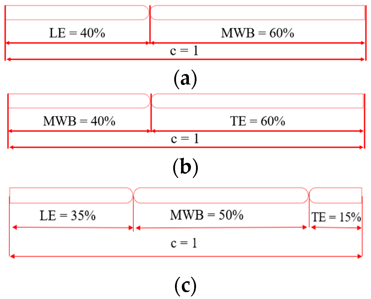
Figure 1. Illustrations of oscillating flat plates: (a) flat plate with a leading flap; (b) flat plate with a trailing flap; and (c) flat plate with leading and trailing flaps.
Energies 17 03010 g001
Figure 2. Dynamics of oscillatory motion: (a) flat plate with a flap; (b) flat plate with two flaps.
Energies 17 03010 g002
Figure 3. The computational zones and grids: (a) computational zone; (b) sub-region grid; and (c) close region of the main wing body and trailing edge.
Energies 17 03010 g003
Figure 4. Comparison of numerical results: (a) C p t of a flatuuplate oscillating wing at R e 1.1 × 10 3 , Usoh et al. [62]; (b) C L for a flat plate at R e 5 × 10 5 , Alam and Sohn [53]; and (c) C p l for a flat plate at the same R e , Alam and Sohn [53].
Energies 17 03010 g004
Figure 5. The calculated results with various ψ o values: (a) the total power coefficient; (b) efficiency at θ O = 85 ° and φ o = 30°.
Energies 17 03010 g005
Figure 6. Vorticity pattern plots evolving over one period, depicted at various time steps: (a) a wing with a leading flap; (b) a wing with a trailing flap; and (c) an oscillating flat plate with two flaps at θ O = 85 ° , ψ o = 45°, and φ o = 30°.
Energies 17 03010 g006
Figure 7. Pressure contour plots evolving over one period, depicted at different time steps: (a) a wing with leading flap; (b) a wing with a trailing flap; and (c) an oscillating flat plates with two flaps at θ O = 85 ° and ψ o = 45°, and φ o = 30°.
Energies 17 03010 g007
Figure 8. Pressure coefficient distribution along the x-direction at t/T = 0.25.
Energies 17 03010 g008
Figure 9. The calculated results with various trailing pitch angle φ o values: (a) the total power coefficient; (b) efficiency at θ O = 85 ° and ψ o = 45°.
Energies 17 03010 g009
Figure 10. Average total power coefficient ( C p t ) for the oscillating flat plate with two flaps: (a) L25%, W55%, T20%; (b) L25%, W60%, T15%; (c) L30%, W50%, T20%; (d) L30%, W55%, T15%; (e) L30%, W60%, T10%; (f) L30%, W65%, T5%; (g) L35%, W50%, T15%; (h) L35%, W55%, T10% at various leading flap pitch angles.
Energies 17 03010 g010aEnergies 17 03010 g010b
Figure 11. Average total power coefficient ( C p t ) for the oscillating flat plate with two flaps: (a) L30%, W50%, T20%; (b) L30%, W55%, T15%; (c) L30%, W60%, T10%; (d) L30%, W65%, T5%; (e) L35%, W50%, T15%; (f) L35%, W55%, T10% at various trailing flap pitch angles.
Energies 17 03010 g011
Table 1. Mesh and time step independence study for the flat plate.
Grid TypeNo. of Moving Body ElementsNo. of Stationary Body ElementsTime Steps/Cycle C ¯ P t MeshVariation   in   C ¯ P t (%) Time   StepVariation   in   C ¯ P t (%)
Coarse 0.6   ×   10 5 0.3   ×   10 5 20000.891
Medium 1.2   ×   10 5 0.6   ×   10 5 5000.904
20000.8870.441.88
40000.883 0.45
Fine 2.6   ×   10 5 1.2   ×   10 5 20000.8860.11
Table 2. Length percentages and pitch angles of a wing with and without flaps.
Wing
Configuration
Wing without
Any Flaps
Wing with
Leading Flap
Wing with
Trailing Flap
Flap ConfigurationWingWingLeadingWingTrailing
Length
percentage
100%60%40%40%60%
Pitch angle θ O = 75° θ O = 95° ψ o = 45° θ O = 50° φ o = 45°
Table 3. The calculated results for the coefficient oscillating flat plate with leading and trailing flaps at θO = 85° and φo = 30°, associated with different ψo values.
Configuration
Type
Wing
with
Leading Flap
Wing
with
Trailing Flap
Oscillating Flat Plate with Leading and Trailing Flaps
Pitch angle, φ o 25°30°35°40°45°50°
C pl 1.5441.4291.1881.3561.4221.4581.4891.432
C pm −0.360−0.251−0.045−0.188−0.216−0.239−0.263−0.246
C pt 1.1831.1771.1421.1671.2051.2191.2251.186
Δ C pt (%)−3.46−1.351.853.043.550.25
η43.0143.4942.2343.1544.5645.0845.3043.86
Δ η (%)−1.820.323.594.795.321.95
Table 4. The calculated results for the coefficient oscillating flat plate with leading and trailing flaps at θO = 85° and ψo = 45°, associated with different φo values.
Configuration
Type
Wing
with
Leading Flap
Wing
with
Trailing Flap
Oscillating Flat Plate with Leading and Trailing Flaps
Pitch angle,
φ o
10°15°20°25°30°35°
C pl 1.5441.4291.4231.4501.4701.4831.4891.473
C pm −0.360−0.251−0.234−0.248−0.257−0.2610.263−0.258
C pt 1.1831.1771.1891.2011.2131.2211.2251.215
Δ C pt (%)0.501.522.533.213.552.70
η43.0143.4944.2944.6444.9945.2245.3044.86
Δ η (%) 2.973.784.585.125.324.29
Table 5. The calculated results with various length percentages at ψ o = 45°, θ O = 85°, and φ o = 30°.
Leading Flap
Length
Wing
Length
Trailing Flap
Length
C p l C p m C p t η
35%55%10%1.469−0.2791.18944.23
30%55%15%1.489−0.2631.22545.30
25%55%20%1.456−0.3241.13241.58
40%50%10%1.422−0.2881.13342.15
35%50%15%1.514−0.3071.20744.63
30%50%20%1.495−0.2721.22244.89
Table 6. The calculated results with different length percentages at ψ o = 50°, θ O = 85°, and φ o = 30°.
Leading Flap
Length
Wing
Length
Trailing Flap
Length
C p l C p m C p t η
25%60%15%1.479−0.3071.17243.32
30%55%15%1.432−0.2461.18643.86
30%60%10%1.437−0.2421.19444.42
35%50%15%1.369−0.2241.14442.30
30%50%20%1.532−0.2961.23545.37
Disclaimer/Publisher’s Note: The statements, opinions and data contained in all publications are solely those of the individual author(s) and contributor(s) and not of MDPI and/or the editor(s). MDPI and/or the editor(s) disclaim responsibility for any injury to people or property resulting from any ideas, methods, instructions or products referred to in the content.