Abstract
As the utilization of wind power systems continues to increase, reducing overall system inertia, there is a consequential negative impact on the power system’s ability to regulate frequency. Consequently, this study focuses on examining the fast-frequency regulation in high penetration of wind power, especially doubly fed induction generators—the most commonly installed wind turbine type, and an energy storage system installed in the wind farm. This study proposes a coordinated control of wind turbine generators and battery energy storage systems that provides fast-frequency regulation to the system while simultaneously ensuring the safety of the battery. Firstly, the fast-frequency regulation capability of the wind turbine will be studied. Secondly, primary frequency control of the battery energy storage system considering adaptive droop control based on state of charge is proposed to prevent both over-charging and over-discharging of the battery. Finally, this study proposed a coordinated fast-frequency regulation approach for the hybrid wind-storage system, which is evaluated under various wind speed scenarios. This approach involves a detailed analysis of the operational characteristics of the wind turbine generators to ensure optimal performance. The proposed method is validated through simulation using a MATLAB model of the wind-storage system, and comparative results with alternative control methods confirm the effectiveness of the proposed approach in raising the frequency nadir and avoiding the secondary frequency dip.
1. Introduction
Variable Speed Wind Turbines (VSWTs), such as doubly fed induction generators (DFIGs), have been extensively employed in the world. In addition to the maximum power point tracking (MPPT) controls of VSWTs, the capability of frequency regulation by VSWTs becomes more important because the penetration of wind power generation increases rapidly. Generally, the frequency support function of a VSWT falls into two categories: power reserve control [1,2] and inertial control [3,4,5,6,7]. However, the utilization of power reserve control faces economic challenges, as it prevents VSWTs from operating in the MPPT mode. Thus, the practical application of power reserve control in wind farms is infrequent.
To enhance the performance of frequency regulation, numerous hybrid control approaches have been proposed, which combine different control strategies. For instance, a combination of droop and virtual inertia control loops within the rotor-side converter (RSC) of DFIGs has been suggested [5,6,7,8,9]. In [8], a real-time pitch angle control was combined with both power reserve control and droop control to fully utilize the reserve power of VSWTs. References [10,11] combined power reserve control with virtual inertia control. Reference [12] applied a power reserve control with adaptive inertia and droop coefficients, which dynamically adjusts inertia and droop coefficients. The main drawbacks of utilizing real-time frequency control include its slow response and the dependence on inertia and droop coefficients. For instance, with a high gain, VSWTs could release more SKE and effectively improve the frequency nadir and the rate of change in frequency (ROCOF); however, it may cause a secondary frequency dip (SFD) due to the recovery of rotor speed. For a lower gain, VSWTs can maintain a stable operation but it cannot provide much SKE for frequency regulation. To enhance inertial response, stepwise inertial controls (SIC) promptly boost the output upon an event detection and maintain an increased power for a predefined power reference curve [13,14,15]. Various SICs may be effective for improving the frequency-response characteristics compared to conventional droop-inertia frequency control loops [3,4,16,17] because they release more SKE at the initial phase of each event. However, SIC methods could also lead to an SFD due to an abrupt reduction in power output [18]. Among various SICs, the ramp-like approaches result in a smaller SFD than the step-like methods, but both of them may induce over-deceleration of rotor speeds due to an excessive release of SKE.
A torque-limit-based frequency control would efficiently release more SKE to enhance the frequency response and reduce over-deceleration [19,20]. When an event is detected, VSWTs promptly boost their outputs to the torque limit and subsequently reduce the power outputs with rotor speeds; this control strategy may guarantee the convergence of rotor speeds to a stable operating range. However, when VSWTs finish the process for frequency support, the SFD may occur due to a sudden power imbalance, which would reduce frequency stability [19,20].
To ensure a continuous power balance, the battery energy storage systems (BESSs) have become a significant component in power systems because of the characteristics of flexible control, stable power generation, and rapid power response, making BESSs suitable for maintaining frequency response and improving frequency nadir. In [21], BESSs were combined with VSWTs that include virtual inertia control to enhance frequency regulation capability. Using real-time frequency deviation as the input of the BESS controller can improve the frequency response. In a high wind power penetration, the fluctuations of power output from VSWTs would lead to an unbalancing between generation and load, causing a severe SFD. In [22], the required BESSs capability to mitigate power fluctuation from a wind farm was discussed, where BESSs were used to reduce frequency deviations. Nevertheless, implementing this coordinated strategy could reduce the lifespan of BESSs because of frequent over-charging and over-discharging operations, which causes higher maintenance costs. To avoid it but assist the frequency control of VSWTs, the state of charge (SOC) of BESSs should be considered. That is, the SOC must maintain within a reasonable range, thus extending the service life of BESSs. Furthermore, to optimize the utilization of wind energy, coordinated control between VSWTs and BESSs must be designed during the process of frequency regulation. The main purpose of the coordinated operation between BESSs and VSWTs is to provide a fast-frequency response (FFR) and enhance the frequency control strategy. This is achieved mainly by improving the frequency nadir and mitigating possible SFDs during the restoration of rotor speeds of VSWTs.
The main motivation behind this study is to leverage the combined capabilities of DFIG-VSWTs and BESSs in a hybrid system to enhance the grid’s frequency response. The coordinated control approach ensures that the system can provide FFR effectively, thereby improving the overall stability and reliability of the power grid. Hence, this study emphasizes the importance of FFR provided by the DFIG-VSWTs and BESSs hybrid system, particularly during the initial moments of a system disturbance when rapid frequency support is critical. Furthermore, proper battery sizing is crucial for economic viability, preventing unnecessary costs from oversized batteries and ensuring reliable frequency regulation. This study assumes that BESS releases energy equivalent to the SKE from VSWTs for FFR and power loss coverage. Optimizing battery size balances performance and cost, justifying the investment. Additionally, the proposed SOC-based adaptive droop control adjusts characteristics based on SOC, preventing over-charging and over-discharging, extending battery lifespan, and reducing maintenance costs. These strategies enhance system reliability, potentially leading to higher revenues from grid support services.
Thus, the innovation of this paper lies in evaluating the FFR capabilities of DFIG-VSWTs and BESSs hybrid systems. This paper develops a coordinated approach that integrates the responses of both wind turbines and BESSs. This coordinated control strategy is designed to deliver balanced and effective frequency regulation under various wind speed scenarios. Furthermore, this paper proposes an adaptive droop control for BESS based on the SOC to prevent over-charging and over-discharging. The proposed method ensures that the charging or discharging of BESSs remains within a reasonable range, and contributes to an extended lifespan of BESSs. The proposed method is validated through detailed simulations using a MATLAB model of the developed wind-storage system, and comparative results with alternative control methods confirm its effectiveness in improving the frequency nadir and preventing secondary frequency dips SFD, thus enhancing grid stability in scenarios with high wind power penetration.
This paper proposes a novel frequency control strategy for the hybrid system that combines VSWTs with BESSs. The main contributions of this paper are summarized as:
- A new SOC-based droop control method for BESS is proposed to set the operating constraints to extend the lifetime of BESSs and the economic cost.
- The size of BESS is designed to meet the economic aspect and provide effective frequency support along with DFIG-VSWTs.
- This paper proposes a method to support the frequency response from DFIG-VSWTs using a torque-limit method, which helps DFIG-VSWTs provide FFR and minimize SFD due to rotor speed recovery.
- The VSWTs and BESS can dynamically cooperate for FFR to enhance system frequency. The process of the control strategy comprehensively considers the operational states of both DFIG-VSWTs and BESS, improving frequency stability and mitigating SFD.
- In this study, wind speeds are categorized into different zones, which consider the relationship between wind speed and power output from VSWTs. Considering the wind speed classification, a coordinated frequency control strategy between VSWTs and BESSs is designed. Consequently, the hybrid system that combines DFIG-VSWTs with BESSs can provide frequency regulation across a broader range of wind speeds.
2. Classification of Wind Speed Zones and Frequency Regulation Capability of VSWTs Based on Torque Limit
2.1. Simplified Model of DFIG-VSWT for Frequency Regulation Studies
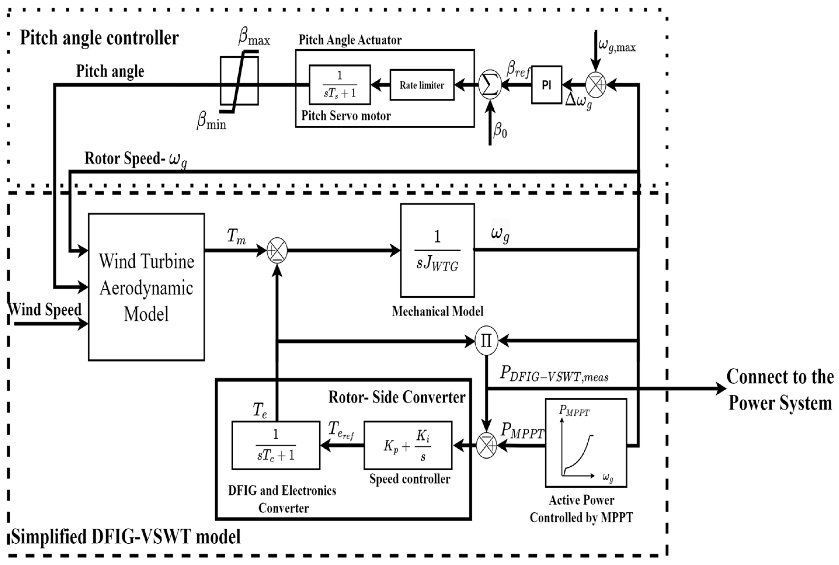
The blades of a VSWT capture wind energy and convert it into mechanical torque. The mechanical energy is then transferred to the electrical energy. Figure 1 shows the block diagram of a simplified electromechanical model of a DFIG-VSWT. It is utilized for the study of frequency control in this paper. The aerodynamic model of a typical DFIG-VSWT comprises the speed multiplier box, wind turbine, and electric generator. Its mathematical equations are shown in the following.
where Pm is the mechanical power of the generator; CP(λ,β) is the wind energy utilization coefficient; λ is the tip-speed ratio; β is the pitch angle; A is the swept area of the blade; ρ is the air density; and v is the wind speed.
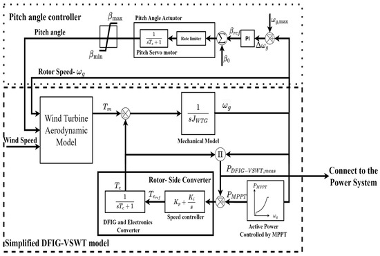
Figure 1.
Simplified model of a DFIG-VSWT.
Equation (2) represents the physical characteristics of a DFIG-VSWT. By applying the Laplace transform, the rotor speed ωg can be obtained by (3).
where Tt is the mechanical torque from blades; Te is electromagnetic torque; n is the number of pole pairs; and JWTG,eq indicates the equivalent inertia coefficient of a DFIG-VSWT.
The pitch-angle controller utilizes hydraulic or electrical pitch servos to adjust the angle of the pitch blades. These servos are represented by a transfer function with a servo time constant Ts. Additionally, the pitch angle actuator model captures the dynamic relationship between the pitch angle reference βref controlled by a PI controller and the initial pitch angle β0.
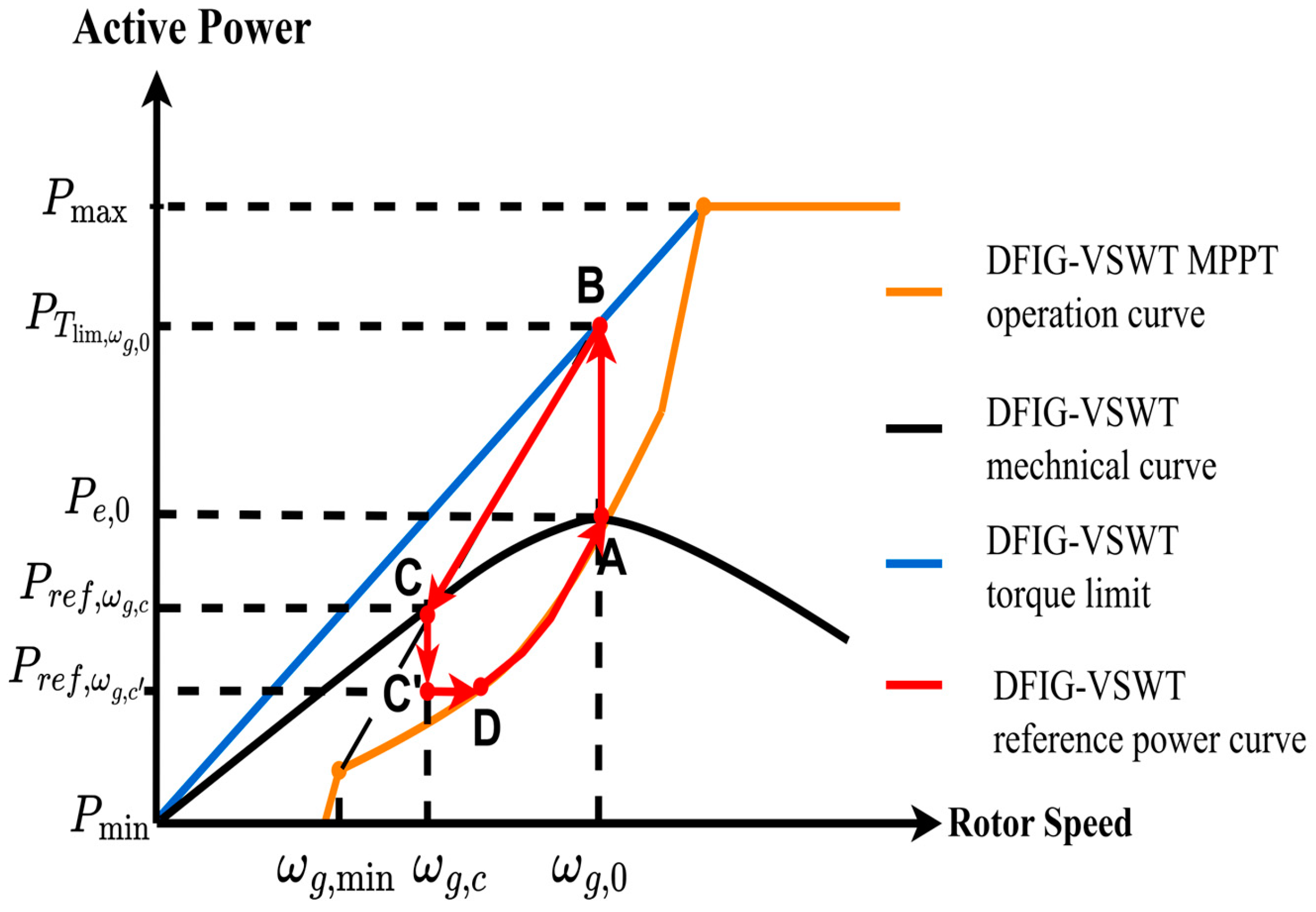
To extract the maximum wind power generation, the speed controller in a DFIG-VSWT typically uses an MPPT technique; its control function can be represented by (4), where Kopt is the optimization constant, whose value depends on the type of DFIG-VSWTs. In Figure 2, the A–B curve marks the initial zone; B–C shows the MPPT operating zone, where the rotor speed can be adjusted. Along with the MPPT operation (B–C curve), the active power reference is obtained and it is applied to the speed controller in the rotor side converter (RSC). In C–D, the rotor speed is changed a little until the DFIG-VSWT reaches its rated power. Beyond D, the pitch angle control takes over.
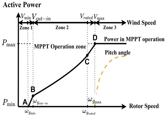
Figure 2.
Operating state diagram of the DFIG-VSWT.
2.2. Classification of Wind Speed Zones
The operating state of DFIG-VSWTs depends on wind speeds, which significantly influence their capability for frequency support. The optimal relationship between rotor speed and power output varies with different wind speeds. Therefore, to design appropriate operational strategies, it is crucial to analyze the performance of DFIG-VSWTs under various wind speed scenarios. For instance, the MPPT operation mode is employed to capture the maximum wind power, and the power output of a DFIG-VSWT is directly linked to the real-time wind speed. Based on the operating characteristics of DFIGs, three wind speed zones are identified:
- Low wind speed zone: in this zone, wind speeds are less than the cut-in wind speed Vcut-in, and the rotor speed of DFIG-VSWT is close to the minimum rotor speed ωg,min. Thus, DFIG-VSWTs cannot provide frequency regulation. These VSWTs are essentially idle or producing negligible power, which limits their contributions to grid stability.
- Medium wind speed zone (optimal operating zone): this zone ranges from the cut-in wind speed Vcut-in to the rated wind speed Vrated. In this zone, DFIG-VSWTs maintain the optimal rotor speed for the MPPT mode, maximizing wind energy capture. Thus, DFIG-VSWTs can support frequency regulation using SKE. These VSWTs operate efficiently, adjusting their outputs dynamically to provide necessary frequency support by temporarily increasing or decreasing their power output in response to grid frequency deviations.
- High wind speed zone: when the wind speed exceeds the maximum wind speed Vmax, the output power of a DFIG-VSWT reaches its rated value Pmax, and the control system starts to adjust the pitch angle to prevent damage from excessive power input. In this zone, the turbine’s ability to contribute to frequency regulation is limited as it operates at its maximum capacity. Therefore, in this zone, DFIG-VSWTs do not contribute to frequency regulation.
According to this classification, the capability of DFIG-VSWTs to support frequency responses under different wind speeds can be analyzed. In the low and high wind speed zones, DFIG-VSWTs do not contribute to frequency regulation. Additionally, due to continuous changes in wind speeds, DFIG-VSWTs cannot ensure reliable frequency-support capability alone. Moreover, with increasing wind power penetration, the variability and unpredictability of wind energy pose significant challenges to maintain grid stability. Higher wind penetration could lead to more frequent and severe frequency deviations if not properly managed.
To address these issues, BESSs are generally used in conjunction with DFIG-VSWTs to enhance frequency-support capability across a wider range of wind speeds. This hybrid approach allows for more stable and reliable frequency regulation. BESSs can provide immediate power compensation, thereby supporting the grid during frequency deviations. By storing excess energy during periods of high wind speeds and releasing it during low wind speed periods, BESS can ensure a more consistent and reliable contribution to frequency regulation. Therefore, combining advanced control strategies with energy storage solutions is essential to mitigate these negative effects. Implementing torque-limit-based frequency control and coordinated control strategies between DFIG-VSWTs and BESSs can optimize the system’s performance, ensuring a more resilient and stable power grid in the face of increasing renewable energy integration.
2.3. Torque-Limit-Based Frequency Control Scheme for a DFIG-VSWT
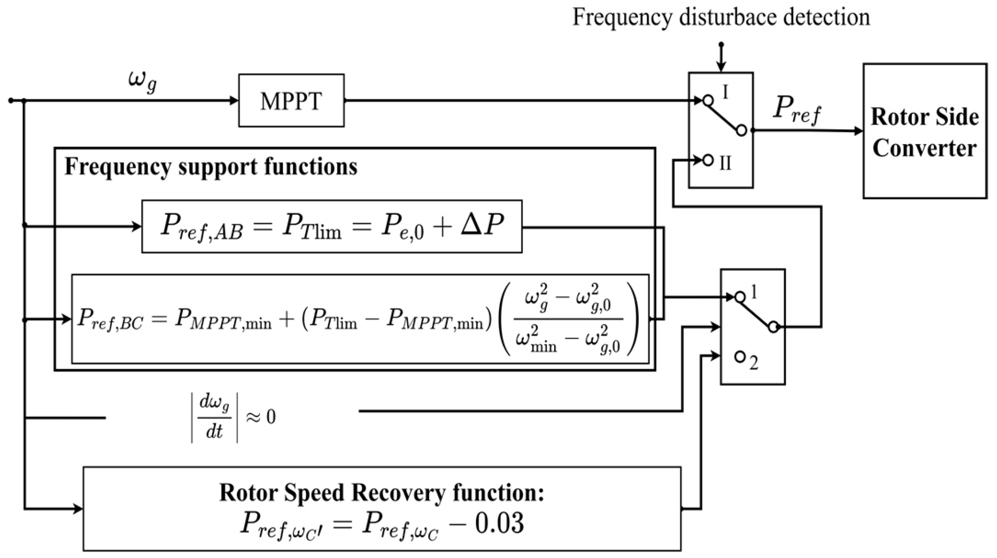
Figure 3 shows the block diagram of the torque-limit-based frequency control scheme of a DFIG-VSWT, and Figure 4 shows the power trajectory from a DFIG-VSWT during the frequency regulation process. As shown in Figure 3, during normal operation, the VSWT operates under the MPPT mode. When a frequency disturbance is detected, the VSWT switches to frequency regulation mode (from state I to II). The frequency regulation mode consists of two functions: the frequency support function (switch 1) and the recovery function for rotor speeds (switch 2). The former aims to release SKE into the system, and the latter aims to recover the rotor speed. The switching action among them is dependent on the signal .

Figure 3.
Block diagram of VSWT torque-limit-based frequency.
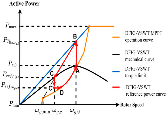
Figure 4.
Active power trajectory of VSWT torque-limit-based control.
When a frequency disturbance is detected, the torque-limit-based scheme instantly raises the power from the MPPT point to a defined reference power that equals the torque limit for providing SKE (the curve A–B in Figure 4). The mathematical equation is given in (5). The incremental power at the instant of frequency disturbance is predetermined based on the torque limit that depends on the current wind speed.
where is the reference power regarding to the torque-limit curve; is the power at a normal operation; is the limit of electrical torque; and is rotor speed.
Since exceeds mechanical power at the initial stage of a frequency accident, starts to decrease until reaches the point. Meanwhile, the is also decreased following (7), i.e., B–C curve.
where is the MPPT power at the minimum rotor speed. is the power reference according to torque limit at the pre-disturbance rotor speed; and are the current rotor speed and pre-disturbance rotor speed, respectively.
At point C, , and converges to , which is higher than minimum rotor . Note that the reference power cannot lead to over-deceleration because the rotor speed cannot be decreased below . During the frequency control period, the rotor speed keeps decreasing with time, because the difference between the reference output power and mechanical power, i.e., , continuously decreases with time.
Additionally, the rate of change in the reference power of DFIG-VSWT, i.e., , is obtained by (8), which represents the slope of the curve B–C in Figure 4.
As shown in (8), is proportional to dωg/dt, which critically depends on . This value decreases with and becomes zero at point C. That is, the output power of a DFIG-VSWT equals to its mechanical power at point C. Therefore, the proposed control scheme ensures a slow reduction rate, and would avoid possible SFD during the deceleration period.
After converging to point C, the proposed scheme starts to recover the rotor speed. That is, when the following condition (Equation (9)) is met, the DFIG-VSWT switches to the recovery operation of its rotor speed.
From point C, to generate an accelerating power for recovering rotor speed, must be less than ; thus, a power reduction is required. However, a significant power reduction would cause a significant SFD. To avoid it, a small power reduction is desirable. Hence, this paper adopts a small power reduction (i.e., 0.03 p.u.) from to , i.e., C–C’ curve. This power reduction is the difference between the actual mechanical power and the electrical power .
This method would increase the recovery time of rotor speed, but it ensures the DFIG-VSWTs can create enough accelerating power and mitigate possible SFDs. After that, the reference power is maintained at until the rotor speed reaches point D. After point D, the DFIG-VSWT returns to the MPPT operation, and the reference power can be restored to Pe,0 (point A) or a new optimal power according to the current wind speed.
3. Dimensioning of the BESSs Capacity
Designing the optimal dimension of BESSs is crucial to balance between investment costs and operating performance. An excessive capacity incurs a higher cost, while an insufficient capacity would result in subpar frequency regulation and possible SFD. A correct selection of the BESS capacity to ensure technical-economic balance has become a mandatory requirement, especially in the high penetration of distributed energy sources.
Currently, there is no unique agreement to design the optimal capacity of a BESS for FFR. One of the suggested methods is to assume that the BESSs release the same energy as that released by SKE from VSWTs to cover the power loss in a certain period. That is, the FFR is supported by both BESSs and DFIG-VSWTs [23]. At the rated rotor speed, the released SKE ΔEWTG_rated from the DFIG-VSWT is:
where ωg,rated is the rated rotor speed; Jeq,WTG is the rotational inertia of DFIG-VSWT; HWTG is the inertia time of DFIG-VSWT; and PWTG is the rated power of DFIG-VSWT.
For example, it is assumed that a DFIG-VSWT releases the maximum SKE from its rotor, so that the rotor speed decreases from ωmax to ωmin, corresponding to the rotor speed from 1.2 p.u. to 0.7 p.u. [24]. Then, the maximum SKE released by the DFIG-VSWT is:
It is assumed that the energy released by the BESS at time t is equal to the SKE released by the DFIG-VSWT:
From (11)–(13), the capacity of the BESS is obtained by:
For simplifying the modeling, it is assumed t H. Therefore, the BESSs capacity can be determined as
The above calculation demonstrates the design of BESSs capacity for FFR, which also considers the rotor speed limit for power recovery. Be aware that the calculated value of 95% PWTG represents a condition with a very severe under-frequency. In practice, the characteristics of the analyzed power grid would affect the appropriate dimension of the BESS capacity. Since the rotor speed of DFIG-VSWTs rarely drops to ωmin in practice, the necessary dimension of battery capacity may even be lower than the result by (15).
4. Frequency Regulation Supported by BESSs
4.1. BESSs Model for Frequency Regulation Studies
The model of BESSs for frequency regulation can be described in Figure 5. The frequency deviation is used as the input of the control model, and the droop control is used to control the power output of BESS. As the frequency deviation Δf is less than zero, the BESS discharges active power to the system. By contrast, as Δf exceeds zero, the BESS is charged.
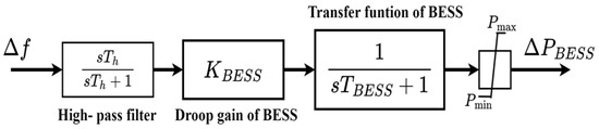
Figure 5.
BESSs with droop control model.
As shown in Figure 5, the product of the first-order transfer function of the BESSs and the droop control gain KBESS is usually used to describe the attribute of BESSs participating in grid frequency regulation, which is expressed in (16). Therefore, as a frequency disturbance occurs, the BESS can release or absorb active power based on the droop gain to provide frequency support [25,26].
where KBESS is the droop gain of BESS; TBESS is the time-response constant of BESS that represents the delay response time between BESS and the power conversion system.
4.2. State of Charge (SOC)–Based Droop Control
SOC represents the proportion of the current charge to the total charge in a fully charged state. As supporting frequency regulation, the BESSs must consider their frequency-regulation capacity based on their SOC. To avoid over-charging and over-discharging of BESSs, designing an appropriate SOC ensures that the charging or discharging of BESSs remains within a reasonable range, and contributes to an extended lifespan of BESSs.
The SOC of a BESSs is calculated by integrating the flowing current [16,23,27]. If the internal voltage of a BESSs is assumed to be constant, the SOC of BESSs can be directly calculated by integrating power, as shown in (17). Furthermore, by applying the Laplace transform, the equation at the time domain can be converted to that at the s domain (18), which helps simplify the analysis of the dynamic characteristics of BESSs. The dynamic equation between SOC and the output power of BESS, e.g., (18), is used to link SOC and the change in power from BESSs.
where SOC0 is the initial SOC, E is a nominal BESS capacity (MWh), h indicates a factor to change one hour to seconds (h = 3600), PBESS is the active power from BESS (MW), ΔSOC(t) = SOC(t) − SOC0, and KE = E · h (MW·s) is the stored energy in BESS.
The droop control in BESSs is designed for frequency regulation, where the droop rate is denoted in (19). When a frequency deviation Δf is detected, the BESS will support the required power for frequency regulation. By combining (18) with (19), the relation between frequency deviation and the change in SOC is represented by (20). Equation (20) represents that the SOC of BESSs is affected by frequency deviation and the controller’s droop gain.
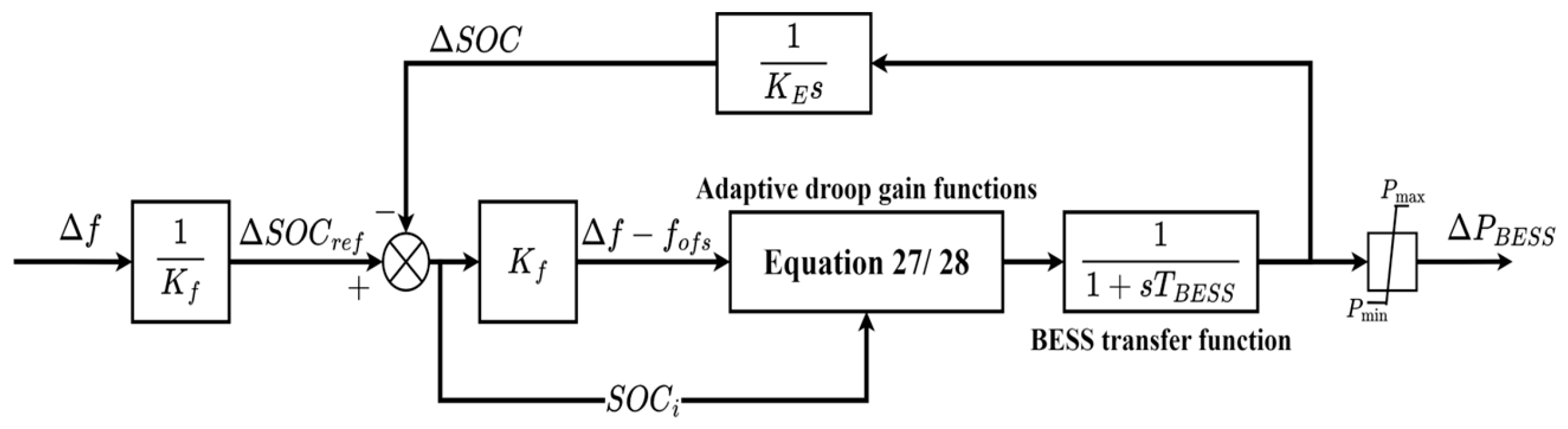
The droop control with SOC feedback is typically used as an energy management method of BESSs for frequency regulation. Figure 6 shows the block diagram of the droop control of BESSs using SOC feedback, which is based on the SOC perspective.
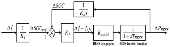
Figure 6.
Block diagram of droop control with SOC feedback method.
As shown in Figure 6, frequency deviation Δf generates the SOC reference ΔSOCref. Equation (21) is used to calculate ΔSOCref by using the center of the SOC range SOCcen for a nominal frequency. This ensures that when the frequency returns to nominal, SOC reference SOCref reaches the central value (50%). The crucial aspect of this method lies in the unit conversion factor Kf. It simplifies the SOC feedback by converting between SOC and grid frequency, as depicted in (22). The frequency offset fofs is used to convert from SOC to the frequency unit. Hence, the fofs can be determined from the measured SOC change ∆SOC and Kf, as in (23).
In this method, for the management of the SOC level, the BESS output power calculation is calculated as in (24) by subtracting the frequency offset fofs from the frequency deviation [28]. When the frequency deviation occurs, the Δf leads to a change in SOC reference deviation ΔSOCref. This adjustment affects the power change ΔPBESS, which is determined by ΔSOCref and measured ΔSOC, leading to a change in ΔSOC. Finally, the difference between ΔSOCref and ΔSOC ΔSOCref(t) − ΔSOC(t) approaches to zero.
where ΔPBESS is the changing output power of BESS; Δf is the frequency deviation; SOCref is the SOC reference; ΔSOCref is the SOC reference deviation from SOCcen; SOCcen is the center of the SOC range, which is denoted as 50%; SOC(t) ranges from 0 to 100(%) during frequency regulation; KBESS is the droop gain of BESSs; fofs is the frequency offset; fofsmax and fofsmin are maximum and minimum frequency offset, respectively.
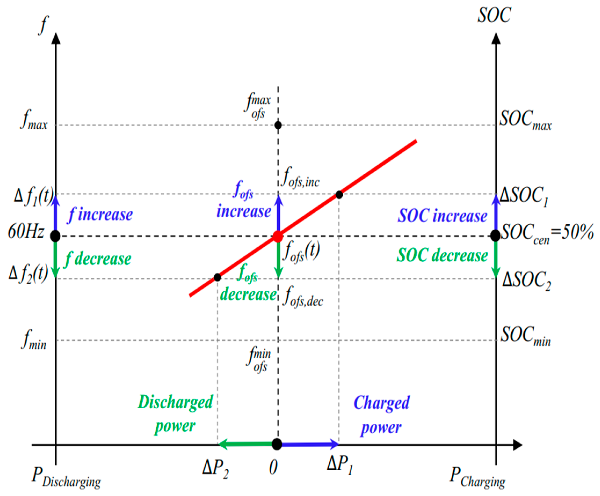
Figure 7 shows the principle of frequency regulation by BESSs. They release or absorb power in response to the variation of grid frequency, resulting in the change in SOC. When the frequency is within the offset range, the SOC does not change. However, SOC changes if the frequency is outside the offset range. Equation (25) presents that the frequency offset is directly proportional to frequency deviation. When grid frequency increases Δf1, the BESSs absorb power as ΔP1, leading to an increase in the SOC by ΔSOC1. Conversely, when grid frequency decreases Δf2, the BESSs discharge power by ΔP2, then and the SOC decreases ΔSOC2.
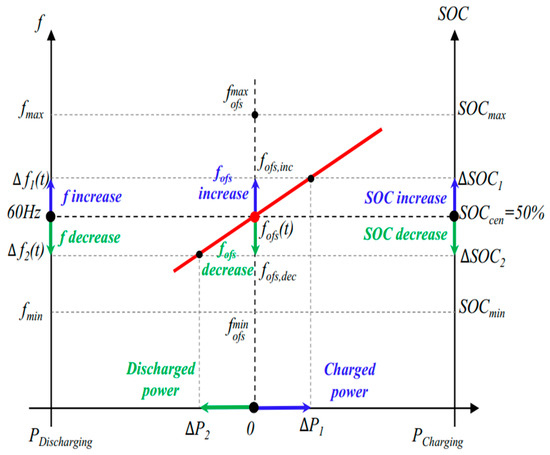
Figure 7.
Operating principle of droop control with SOC feedback.
: SOC increases, indicating the BESS is charging.
: SOC decreases, indicating the BESS is discharging.
The droop control with the SOC feedback ensures that the SOC of BESSs is adjusted proportionally to the frequency deviation. A small frequency deviation causes a small SOC change, while a large deviation leads to a larger SOC adjustment. This approach can automatically manage the SOC of BESSs and help support system frequency.
4.3. Operation Rules for BESSs
When participating in frequency regulation, BESSs should be able to maintain system frequency around its nominal value. The control signal for frequency regulation is passed into the distributed battery management systems (BMSs). The BMSs control the output of the BESS based on the charging and discharging signals. Moreover, the current SOC of each BESS SOCi also affects the frequency regulation setting of BESS, and the supporting power of an aggregated BESS system is limited to its maximum power capacity. In this paper, the rule for frequency regulation in the DFIG-VSWT and BESS hybrid system is listed below.
- Rule 1: If Δf is greater than 0.02 Hz, BESSs will provide FFR to improve the frequency nadir and ROCOF [29].
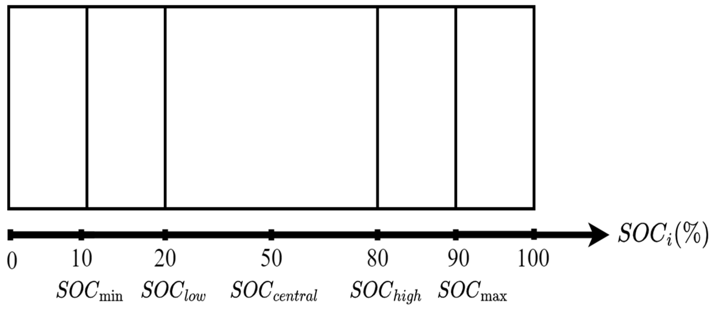
- Rule 2: The SOC can be divided into four intervals with a central SOC of 50%, as shown in Figure 8. The SOCi ranging between 20% and 80% is the optimal operation of BESSs in frequency regulation. If the SOCi is greater than 90%, the power output of BESSs remains at the maximum value, and BESS cannot be charged anymore. Conversely, SOCi is less than 10%, the BESSs cannot be discharged anymore. Furthermore, if the BESS is fully charged (100%) and holding it at that level for prolonged periods can degrade the battery’s health over time. Hence, limiting the charge to 90% helps reduce stress on the battery and can extend its lifespan [10,30].
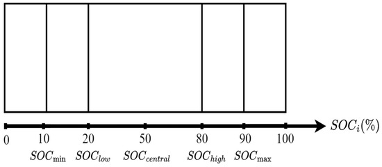 Figure 8. SOC intervals.
: Over-discharge state;
: Critical discharge stages;
: Critical charge stage;
: Over-charge state.
Generally, the SOC-based droop control method is used to avoid over-charging or over-discharging operations of BESSs. Normally, the charging/discharging power is constrained by 5% of the BESS capacity because of safety issues [10,30]. In simulations, the SOCi of BESSs is updated by the following equation:
where SOCi is the current SOC of each BESS, which ranges from 0–100(%) during frequency regulation; ΔSOCref is the SOC reference deviation; ΔSOC is the difference between measured SOC and the initial SOC.
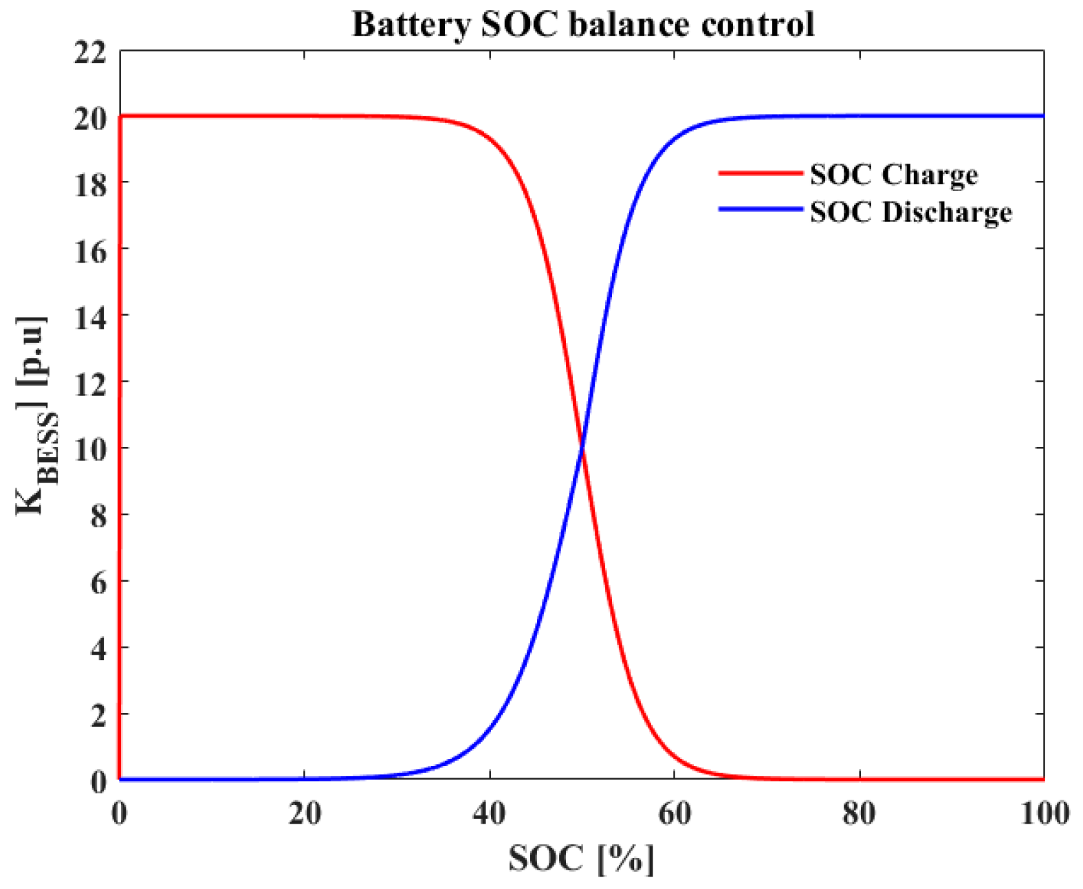
Figure 9 shows the block diagram with an adaptive droop gain of BESSs based on real-time SOC. This diagram represents a modified control strategy based on the SOC-droop control of BESS as depicted in Figure 6. As shown in Figure 9, the frequency deviation Δf is used as the input signal for the BESS response. In this adaptive approach, the droop gain of the BESS is dynamically adjusted according to the real-time SOC. The proposed SOC-adaptive droop control is suggested based on each SOC interval. The SOC-adaptive droop gain is mathematically expressed in (27) and (28). The adaptive droop control based on the SOC curve is illustrated in Figure 10. This adaptive feature enables the BESS to optimize its response to varying grid conditions, ensuring efficient and effective frequency regulation.
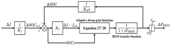
Figure 9.
Block diagram of BESS SOC-adaptive droop control.
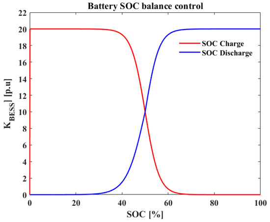
Figure 10.
BESS adaptive droop control-based SOC.
- Adaptive droop control in the case of a discharging operation and an under-frequency disturbance
When , KBESS should become greater to efficiently deliver frequency regulation. In contrast, when , KBESS should be smaller to safeguard the battery. In the case of , KBESS remains at the maximum value to enable BESSs to provide their full potential in frequency regulation.
- Adaptive droop control in the case of a charging operation and an over-frequency disturbance
Contrary to a discharging operation, during a charging operation, when , KBESS should be smaller to efficiently deliver frequency regulation. The range of , KBESS should be set at the smallest value to preserve the lifetime of the battery. Conversely, when , KBESS should be larger to be more effective in frequency regulation.
In summary, the implementation of SOC-based adaptive droop control is a crucial aspect of the economic feasibility of the hybrid system. This control strategy dynamically adjusts the droop characteristics based on the battery’s SOC, ensuring that the battery operates within safe limits and avoids over-charging or over-discharging. Furthermore, the SOC-based adaptive droop control reduces wear and tear on the battery, leading to fewer replacements and lower maintenance expenses.
5. The Proposed Coordinated Frequency Regulation Method for the DFIG-VSWT and BESSs Hybrid System
The DFIG-VSWT stores different levels of SKE according to varying wind speeds. Therefore, it is required to coordinate the controls for a DFIG-VSWTs and BESSs hybrid system for providing frequency regulation at different wind speeds. The designed rule is illustrated below:
- From cut-in wind speed to the rated wind speed: the DFIG-VSWT operates at the MPPT mode. In this wind speed range, the DFIG-VSWTs have low reserved SKE. Thus, when DFIG-VSWTs release SKE for frequency regulation, the rotor speed drops and is closed to the rotor speed limit (0.7 p.u.), causing a severe SFD when the rotor speed is restored. To mitigate a possible SFD caused by VSWTs, BESSs need to participate in frequency regulation under this wind speed range.
- The rated wind speed: DFIG-VSWTs also operate at the MPPT mode. During this wind speed level, the rotor speed of VSWTs is high; thus, it brings a high potential to support frequency regulation. In this wind speed zone, the DFIG-VSWTs and BESSs can collaborate to offer FFR.
- High wind speeds (exceeds 12 m/s): DFIG-VSWTs maintain the maximum power by regulating the pitch angle. Thus, it should avoid DFIG-VSWTs to provide extra power to regulate system frequency. Therefore, it is recommended to use BESSs only to participate in frequency regulation.
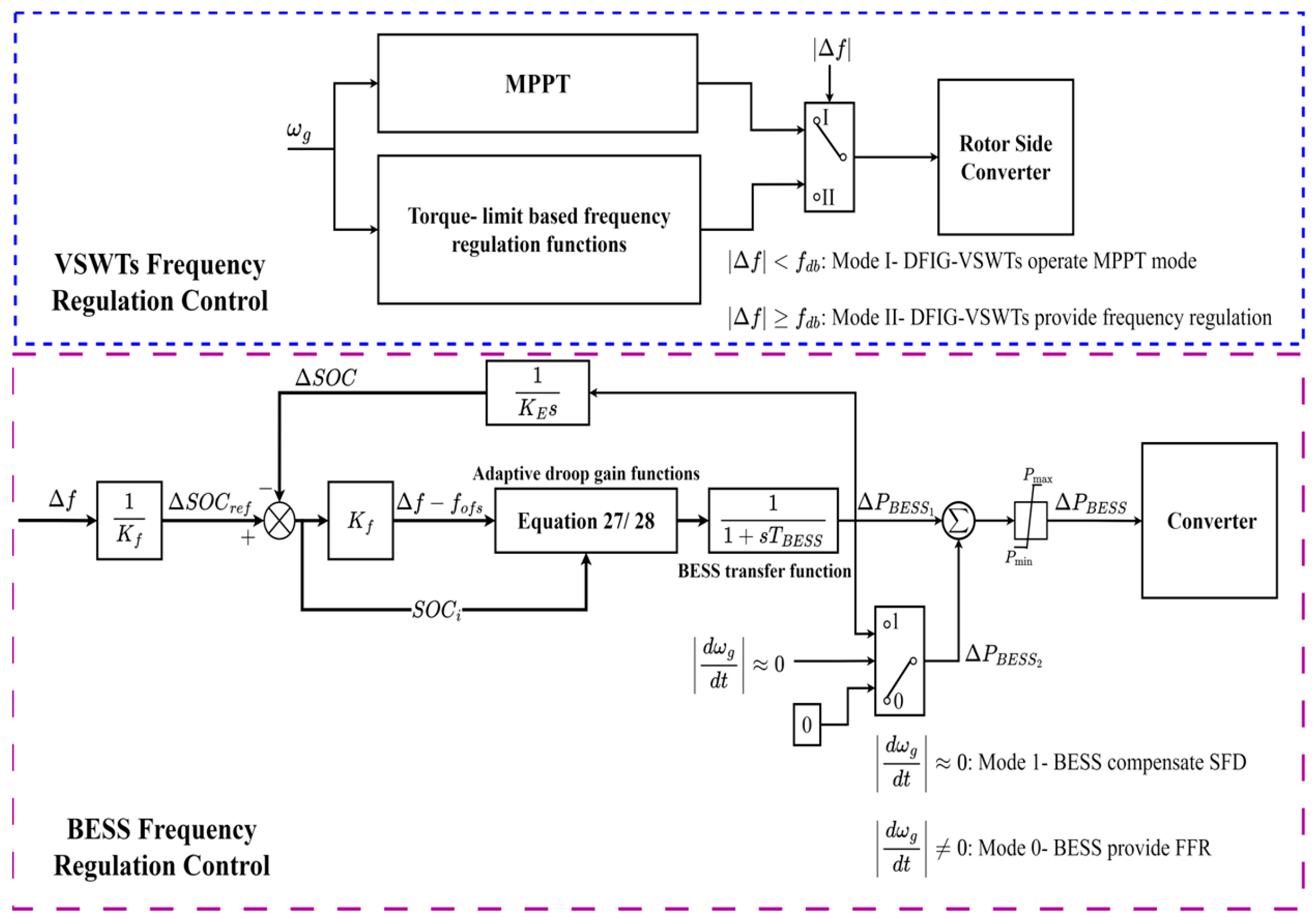
In addition to considering wind speed ranges, the coordinated control for the hybrid system that combines VSWTs with BESSs should also consider different stages during the frequency regulation [23,31], especially for the states of rotor speeds. Figure 11 shows a block diagram of the hybrid DFGI-VSWT and BESSs hybrid system.
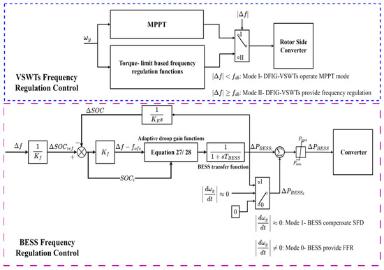
Figure 11.
Block diagram of DFIG-VSWTs and BESSs hybrid system frequency regulation strategy.
As shown in Figure 11, the control diagram consists of two main blocks: the upper block for DFIG-VSWTs and the lower block for BESSs.
- Operating modes of DFIG-VSWTs: the DFIG-VSWTs operate in two modes:
Mode I: MPPT operation—The VSWTs operate under MPPT based on wind speeds.
Mode II: Frequency disturbances—When a frequency disturbance occurs (|Δf| ≥ fdb), VSWTs switch to Mode II, contributing additional power by SKE through the torque-limit-based control.
- Frequency regulation support by BESSs
Simultaneously, BESSs support frequency regulation if their SOC is within the allowed range. In the control block of BESSs, frequency deviation is input to the droop controller, and real-time SOC adjusts the droop gain to improve frequency nadir and ROCOF.
- Mitigate SFD operation
After releasing SKE, the rotor speed of VSWTs decreases due to an imbalance between mechanical and electromagnetic power. Consequently, DFIG-VSWTs switch to under-production, reducing generated power to recover rotor speed. The signal determines when the rotor-speed recovery will start. During this operating stage, BESSs provide additional power to compensate for the power drop from VSWTs (transitioning from Mode 0 to Mode 1), using real-time SOC to determine the necessary supportive power and mitigate potential SFD.
Furthermore, to implement this coordinated control approach in actual wind farms that require integrating control systems for both DFIG-VSWTs and BESSs. The switch control is embedded in the VSWT and battery management system, and the controller monitors wind speed, rotor speed, and frequency deviations in real time. The control algorithms including MPPT, torque-limit-based control, and SOC-based droop control are implemented in their respective controllers. Effective communication systems ensure seamless coordination between DFIG-VSWTs and BESSs for the power output and frequency regulation. Additionally, before a full-scale deployment, extensive testing and validation in simulated environments are conducted to ensure reliability and effectiveness in improving grid stability. This systematic integration optimizes the performance of wind farms and enhances grid contribution.
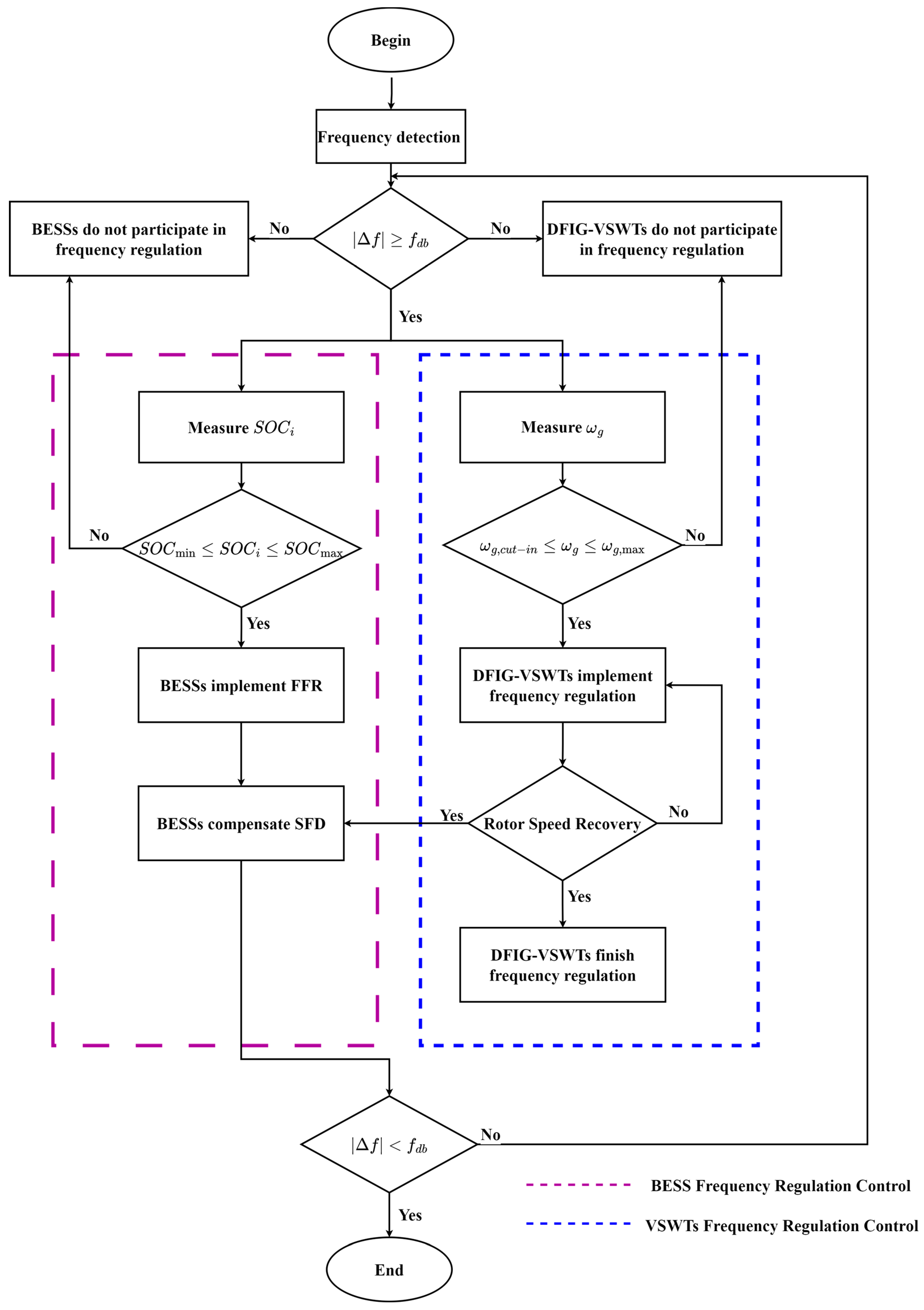
Figure 12 shows the flow chart of the proposed frequency control strategy for the hybrid system. When a large frequency disturbance is detected, the DFIG-VSWTs and BESSs will start to support frequency regulation. The right side of Figure 12 is the process for frequency regulation by DFIG-VSWTs. First, the rotor speed of DFIG-VSWTs is measured. If the rotor speed is within the range between cut-in speed and the maximum speed, DFIG-VSWTs can participate in frequency regulation by releasing their SKE. Simultaneously, the SOC of BESSs is measured to ensure the BESSs ability for frequency regulation. The left side of Figure 12 shows this process. If the SOC is within the allowed range, BESSs can participate in frequency regulation.
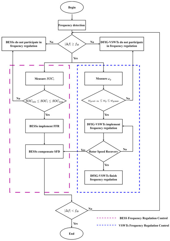
Figure 12.
Block diagram of the coordinated control strategy.
The control process of frequency regulation by DFIG-VSWTs is finished when the rotor speed of VSWTs begins to recover. Meanwhile, BESSs continue to support more power, which aims to mitigate a possible SFD caused by the effect of rotor-speed recovery. Thus, the coordinated control between DFIG-VSWTs and BESSs improves frequency stability.
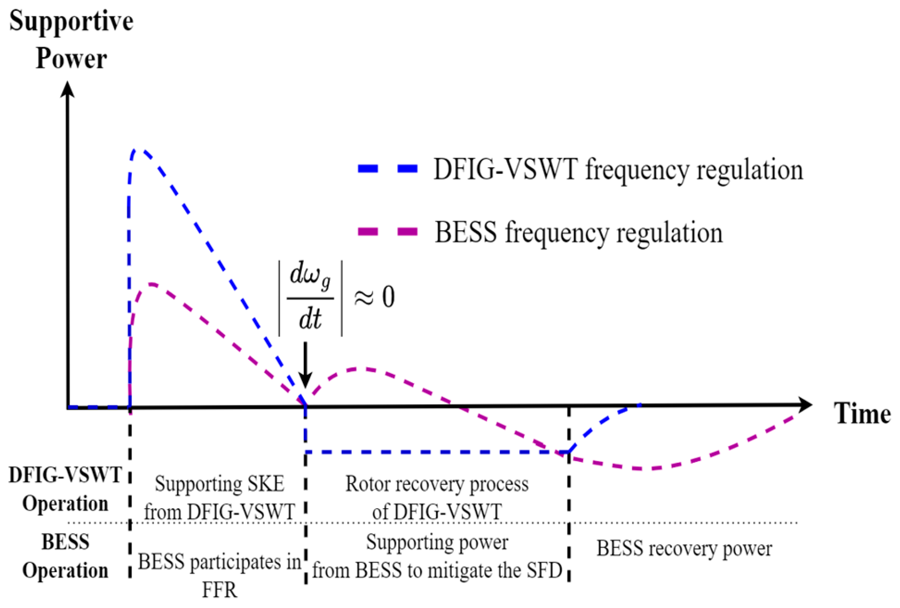
Figure 13 shows the time series of the coordinated control strategy of the DFIG-VSWTs and BESSs hybrid system. The coordinated frequency regulation of the DFIG-VSWTs and BESSs hybrid system will be divided into two stages.
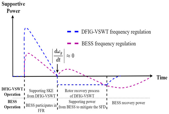
Figure 13.
Time series sequence of the DFIG-VSWTs and BESSs hybrid system.
- Stage 1: Both DFIG-VSWTs and BESSs provide FFR:
When a frequency disturbance occurs, if the rotor speed exceeds the minimum speed, the DFIG-VSWTs start to contribute additional power for frequency regulation by releasing SKE through torque-limit control, which is shown in detail in Figure 3. Meanwhile, BESSs also support frequency regulation if their SOC is within the allowed range. In BESSs, the frequency deviation is taken as an input for the droop controller. Moreover, the real-time SOC is measured to adapt the droop gain of the controller. At this stage, it aims to improve frequency nadir and ROCOF.
- Stage 2: Auxiliary frequency support by BESSs:
After releasing the SKE in VSWTs, the rotor speed of VSWTs decreases owing to an imbalance between mechanical power and electromagnetic power. Thus, DFIG-VSWTs switch to under-production operation, which reduces generated power to recover the rotor speed. The signal is used to determine when DFIG-VSWTs begin to recover rotor speed. At this point, BESSs provide additional power to compensate for the power drop in VSWTs. In this process, the real-time SOC of BESSs is applied to determine the supportive power to mitigate a possible SFD.
6. Simulation and Results
The proposed method is validated on a simplified frequency-response system as shown in Figure 14. This power system includes DFIG-VSWTs, traditional synchronous generators, and BESSs. The specification of the DFIG-VSWTs is shown in Table 1 [24]. All VSWTs have identical parameters and actively support frequency regulation. The equivalent 15 MW synchronous generator model includes re-heat governors with parameters in Table 2 [24]. The traditional synchronous generator contributes approximately 60% of the system load, while the DFIG-VSWTs are responsible for the rest. The installed capacity of the BESS in this paper is designed to be 80% of the installed capacity of DFIG-VSWTs, rather than 95% shown in Equation (15). This design aims to achieve a cost-effective operation. An 80% capacity reduces initial investment costs, which would avoid over-sizing the BESS. The detailed specifications of the used BESSs are shown in Table 3, and the initial SOC of the BESS operates in nominal frequency is SOCcen (50%).
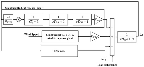
Figure 14.
Block diagram of the system.

Table 1.
Parameters of a DFIG-VSWT.
Table 2.
Parameters of re-heat governor and the used power system.
Table 3.
Parameters of BESSs.
To study the frequency control techniques by the DFIG-VSWTs, the simplified model aims to speed up the computation that is required for the controllers. The simplified model in Figure 14 is modified and extended from [32]. Since the simplified model focuses on the issue of active power and frequency control, the related control for reactive power was eliminated.
The simulation compares the control strategies among the coordinated DFIG-VSWTs and BESSs hybrid control and stand-alone ones to verify the effectiveness of the proposed FFR strategy by the hybrid system. The simulation software in this study was the MATLAB version 2024a. The DFIG-VSWTs in all strategies have the same parameters and have the same Torque-limit-based frequency regulation control. The BESSs in all cases also have the same parameters and the SOC-adaptive droop control. The comparison is conducted across three distinct wind speed levels, as detailed in Table 4.
Table 4.
Simulation scenarios.
The selection of these specific wind speeds might be based on standard operational thresholds and performance characteristics of a typical wind turbine:
Below-Rated Wind Speed (8.4 m/s): This speed is selected as a representative speed below the rated speed but within the optimal operation range of the VSWT. It is a typical value where the VSWT can still generate power efficiently but is not at its maximum capacity. Selecting 8.4 m/s allows the analysis of frequency control when the VSWT operates in a partial load condition.
Rated Wind Speed (12 m/s): This is the wind speed at which the VSWT generates its maximum rated power. It is a critical point for assessing the frequency control performance since it represents the turbine’s full-load operation.
Constant High Wind Speed (14 m/s): This speed is chosen to represent a scenario where the wind speed is high but within the operational limits of the turbine (below the cut-out speed, which is 20 m/s). In this zone, the output power of a DFIG-VSWT reaches its rated value, and pitch control is likely used to regulate power output. Hence, the DFIG-VSWT cannot provide extra power to regulate the system frequency drop; otherwise, its power output will exceed the rated value.
By selecting these specific wind speeds, this study can evaluate the performance of frequency control strategies across different operational states of the VSWTs, including partial load, full load, and high wind conditions. This selection provides a comprehensive understanding of the control strategy’s effectiveness and stability across a range of typical operating scenarios.
6.1. Case 1: Constant Below-Rated Wind Speed: Vw = 8.4 m/s
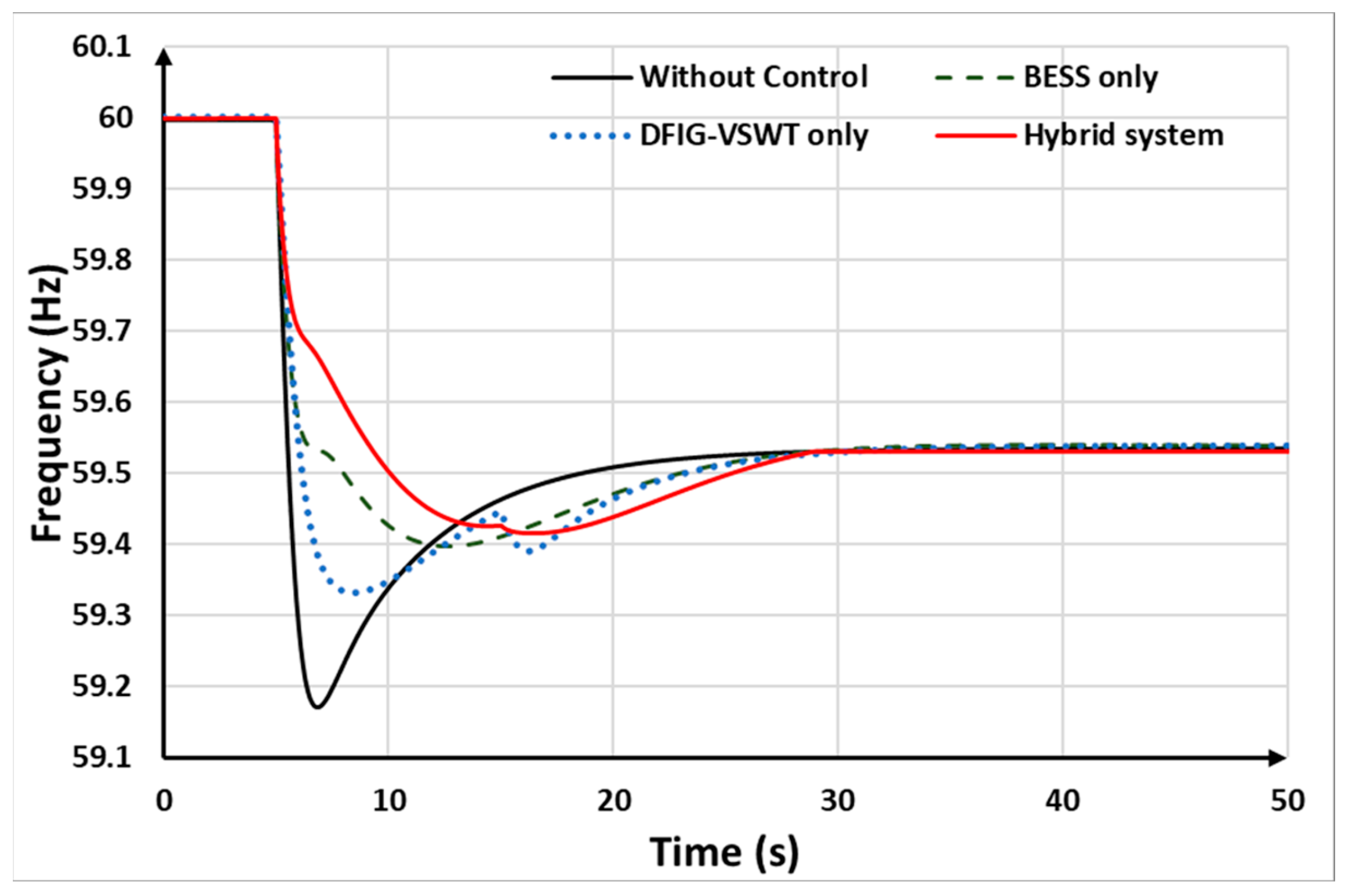
The DFIG-VSWTs operate under a wind speed of 8.4 m/s. In this case, the DFIG-VSWTs operate at the MPPT mode, and its rotor speed is high enough for effective frequency regulation. In this scenario, it is assumed that the synchronous generators trip offline 10% of power at 5 s. The simulation results are shown from Figure 15, Figure 16, Figure 17, Figure 18 and Figure 19.
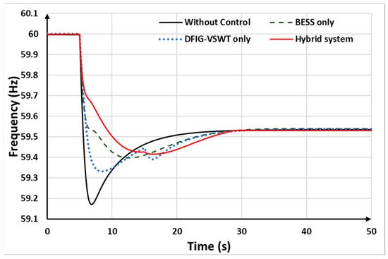
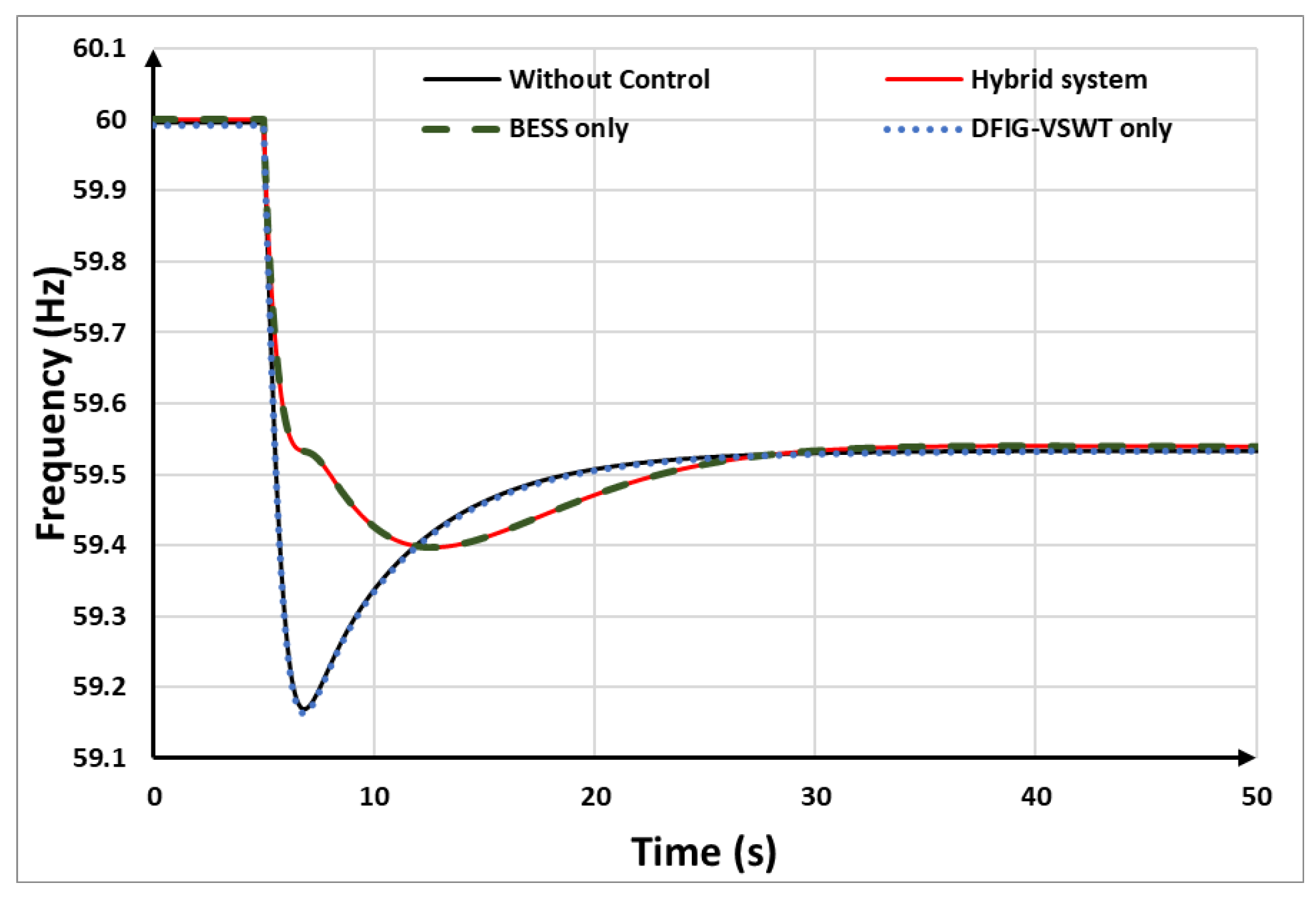
Figure 15.
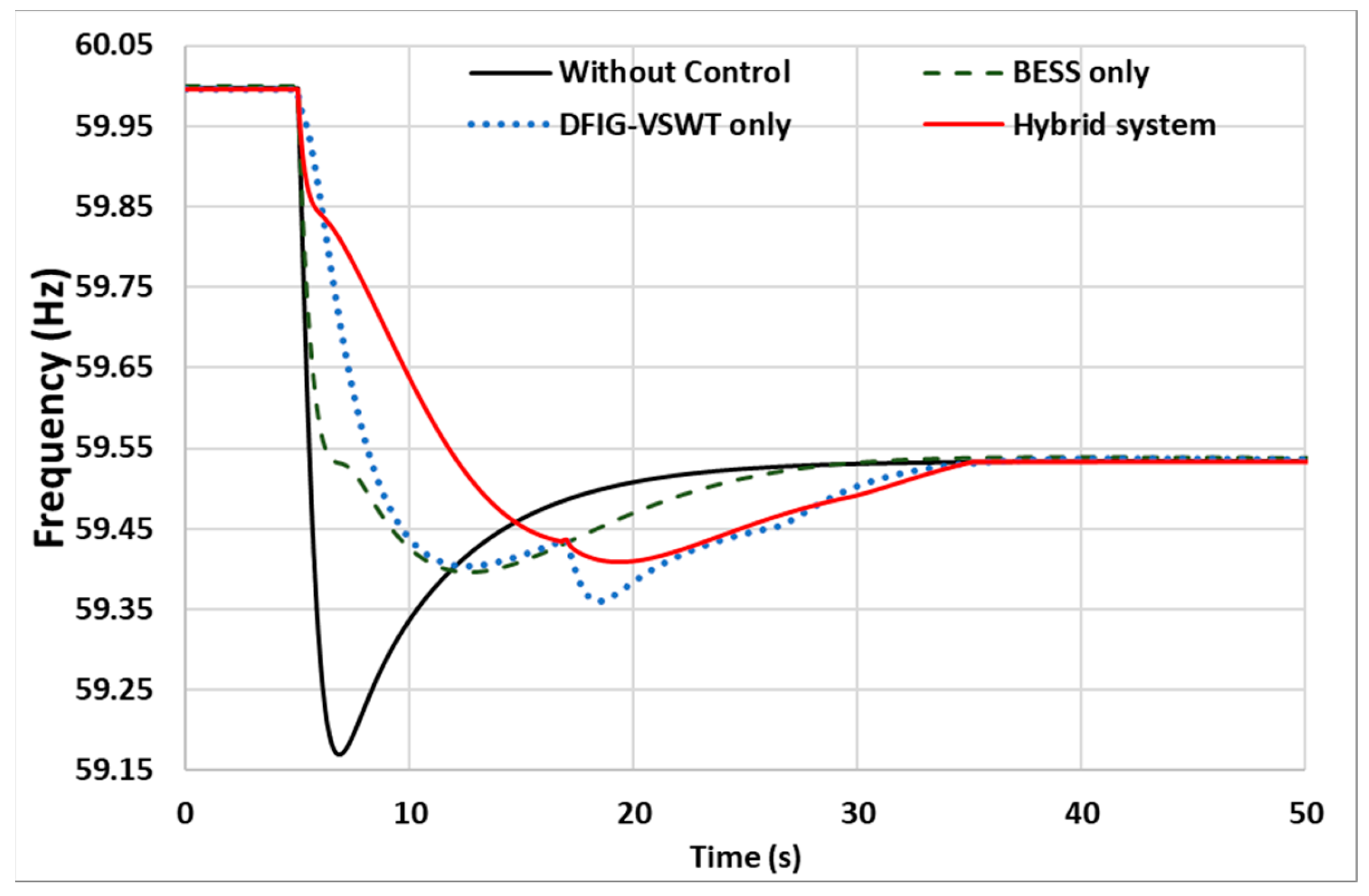
System frequency in case 1.
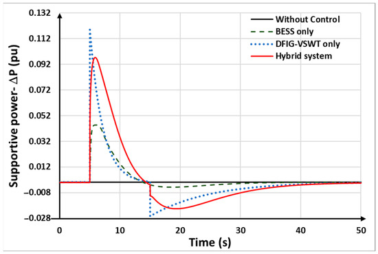
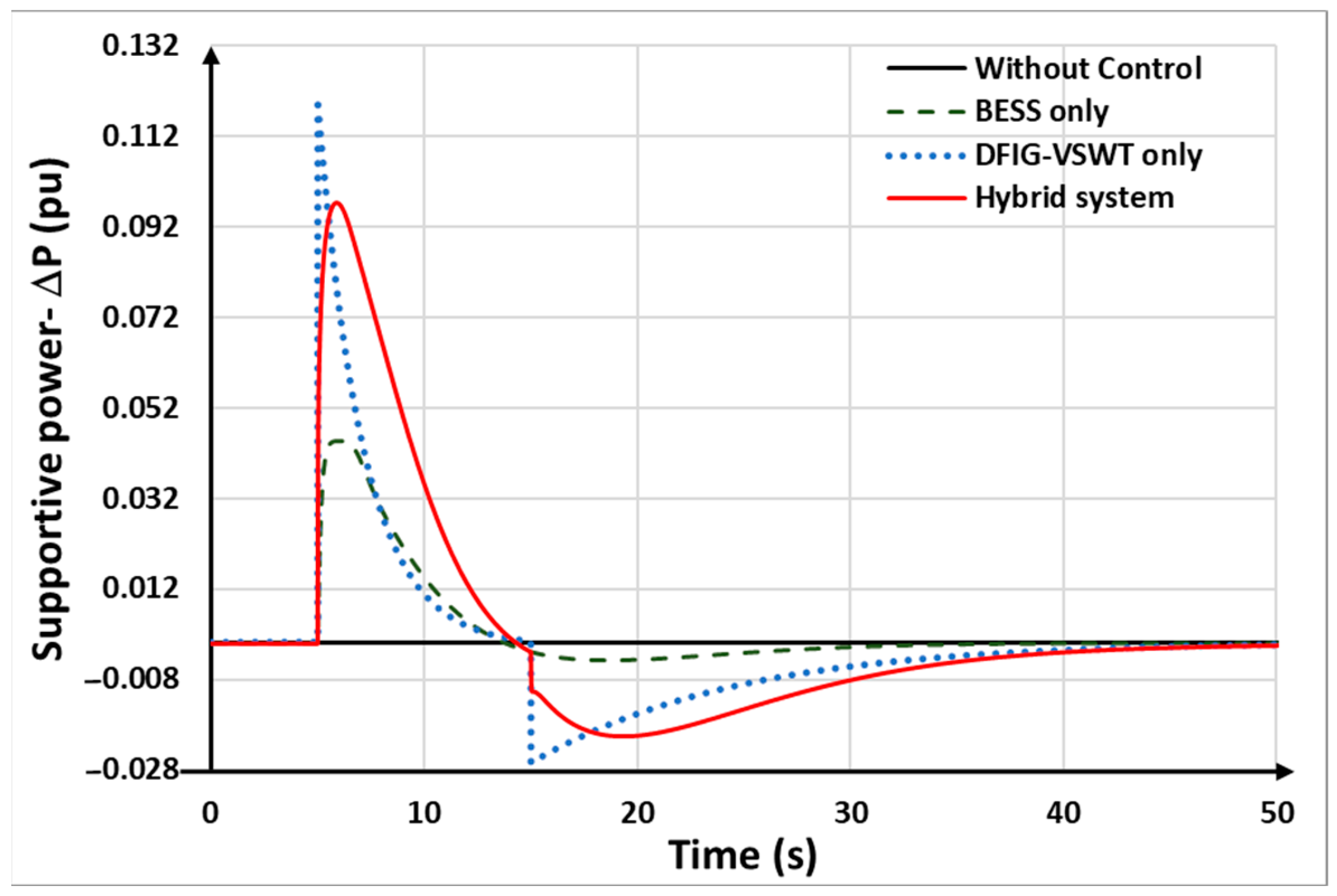
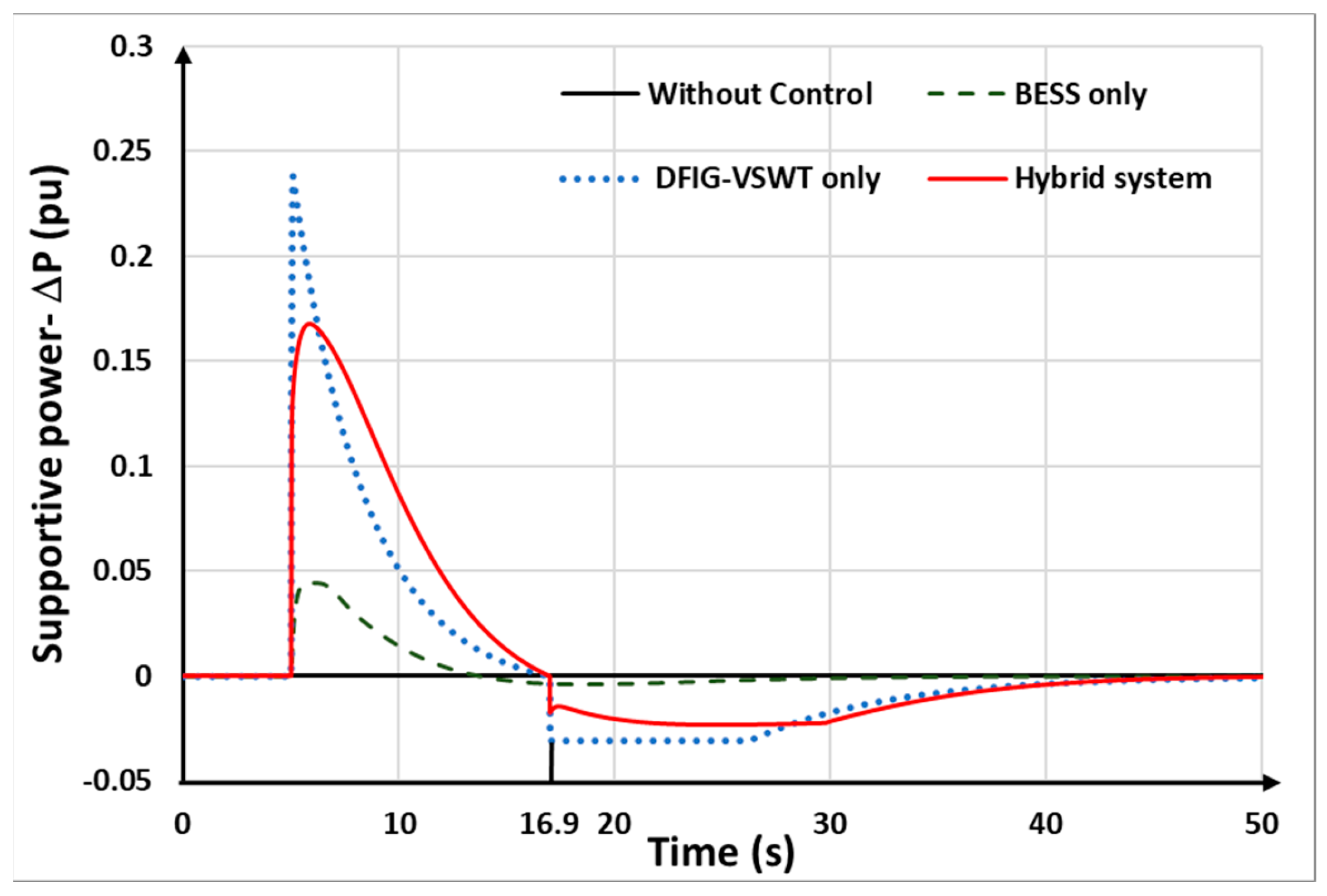
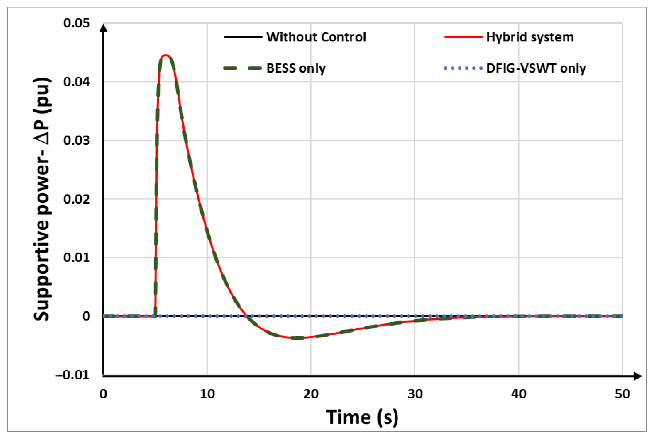
Figure 16.
Comparison of the overall supportive power in case 1.
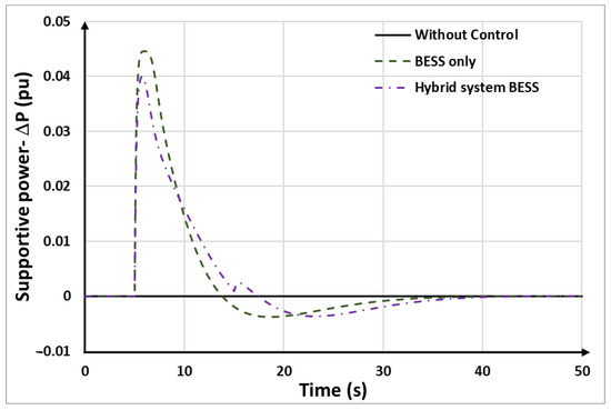
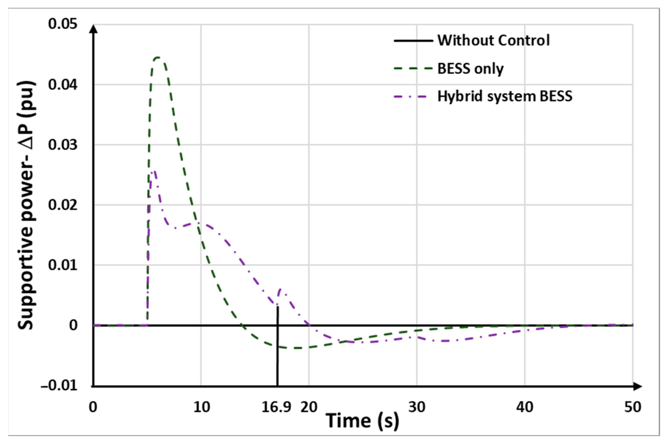
Figure 17.
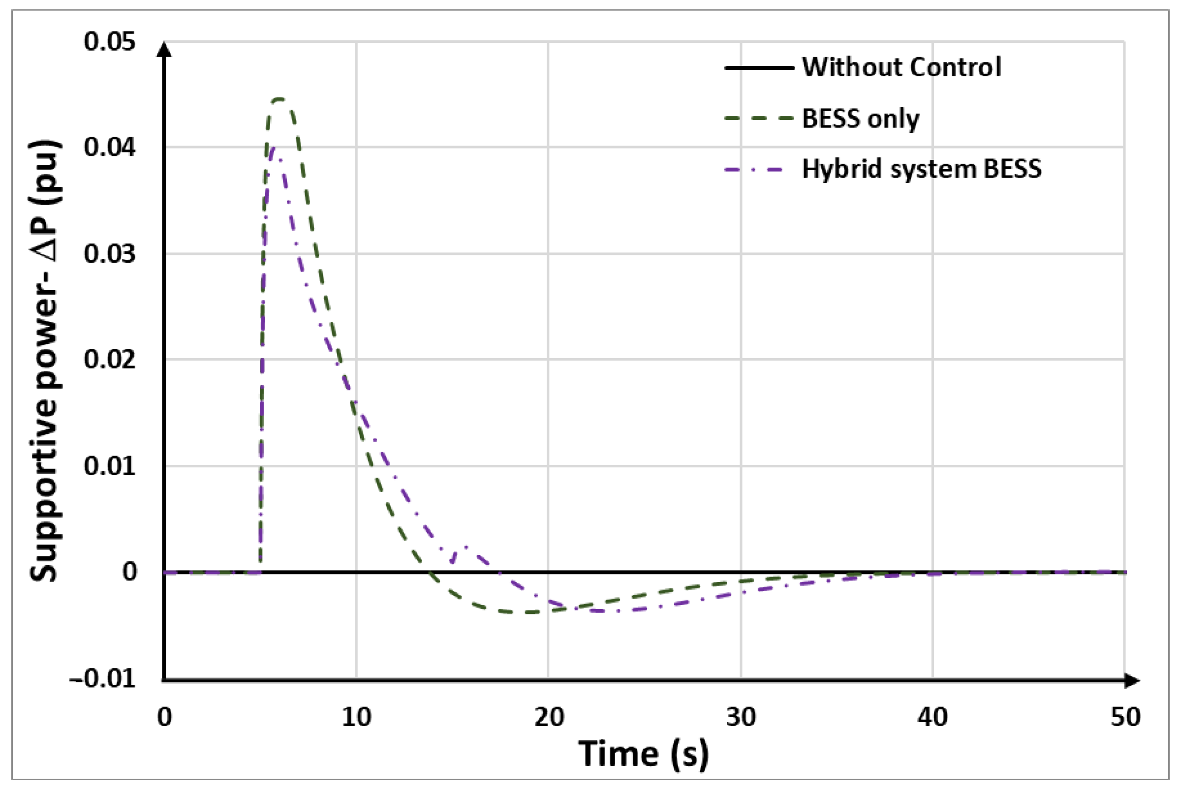
Comparison of supportive power of BESSs in case 1.
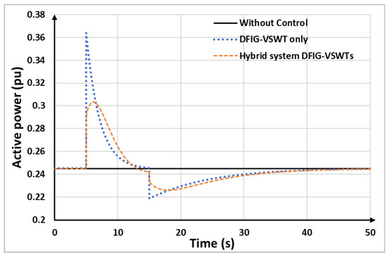
Figure 18.
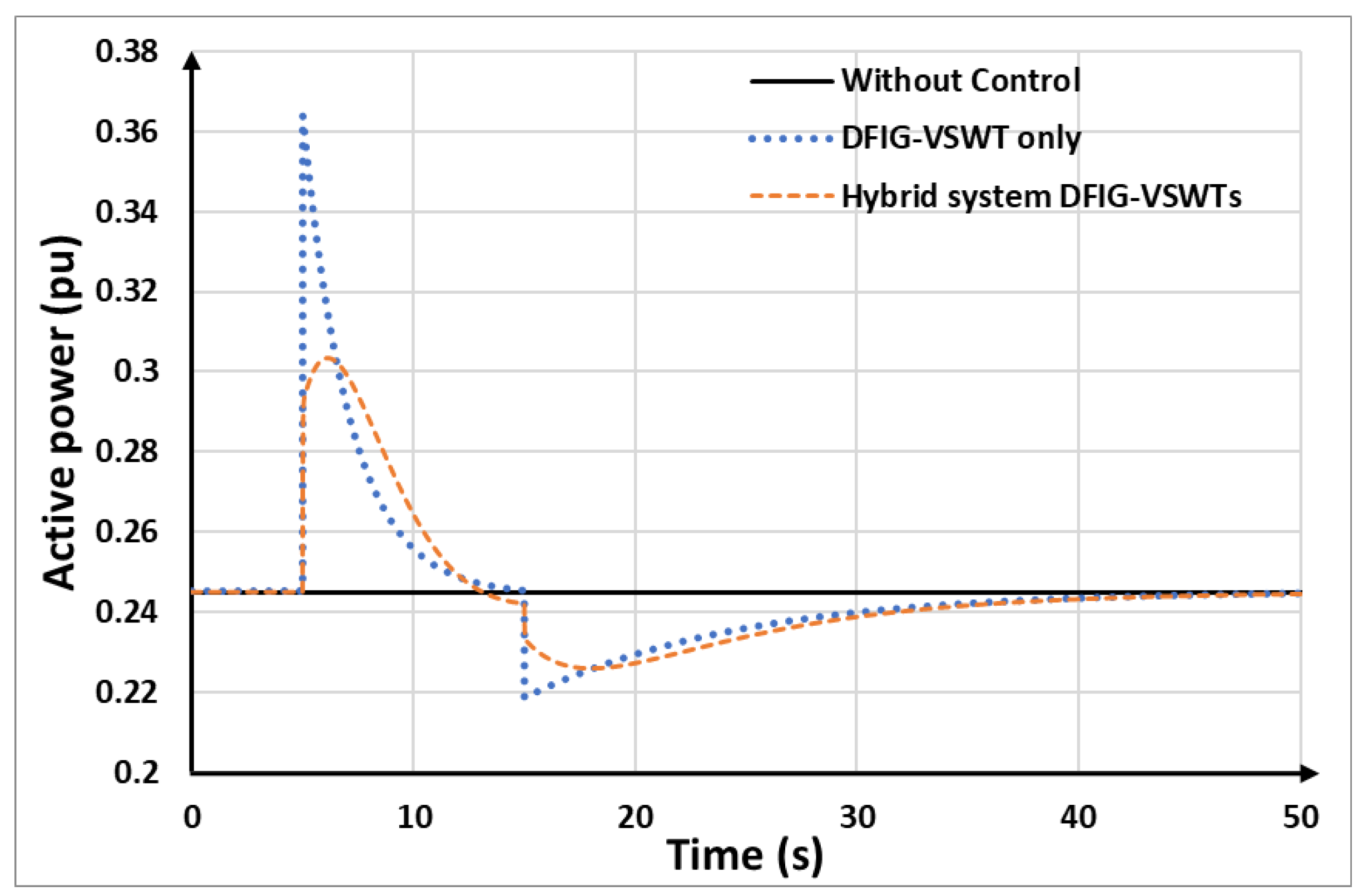
Comparison of active power of DFIG-VSWTs in case 1.
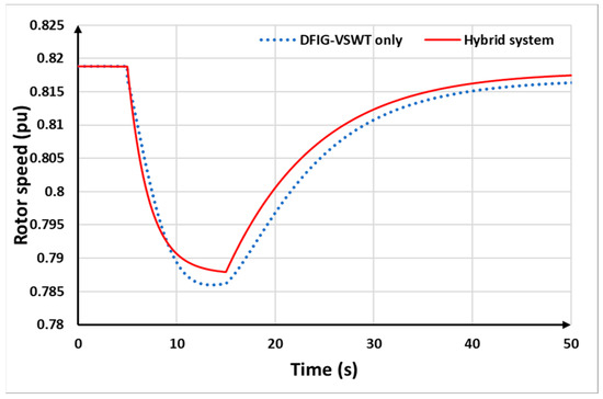
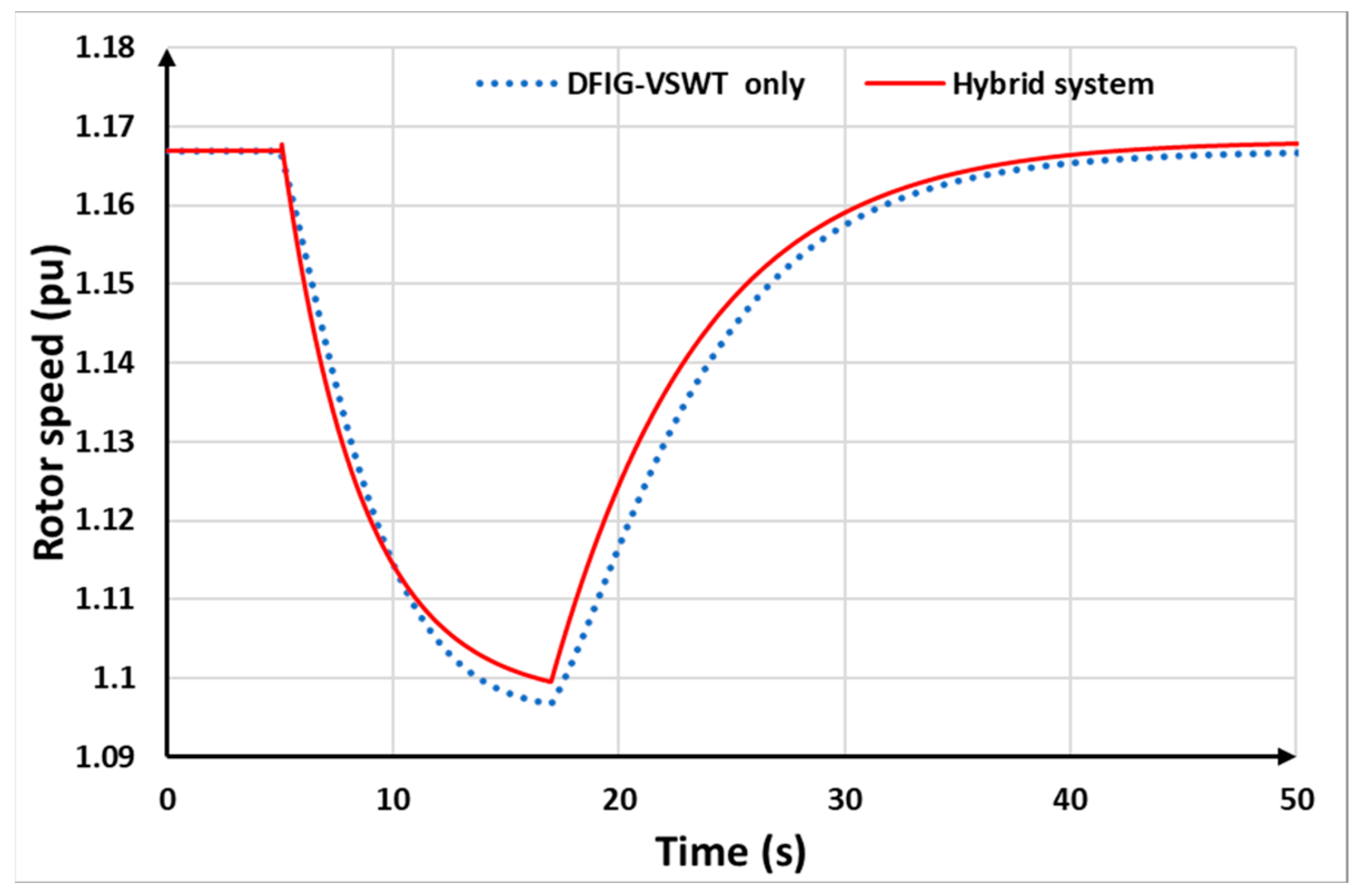
Figure 19.
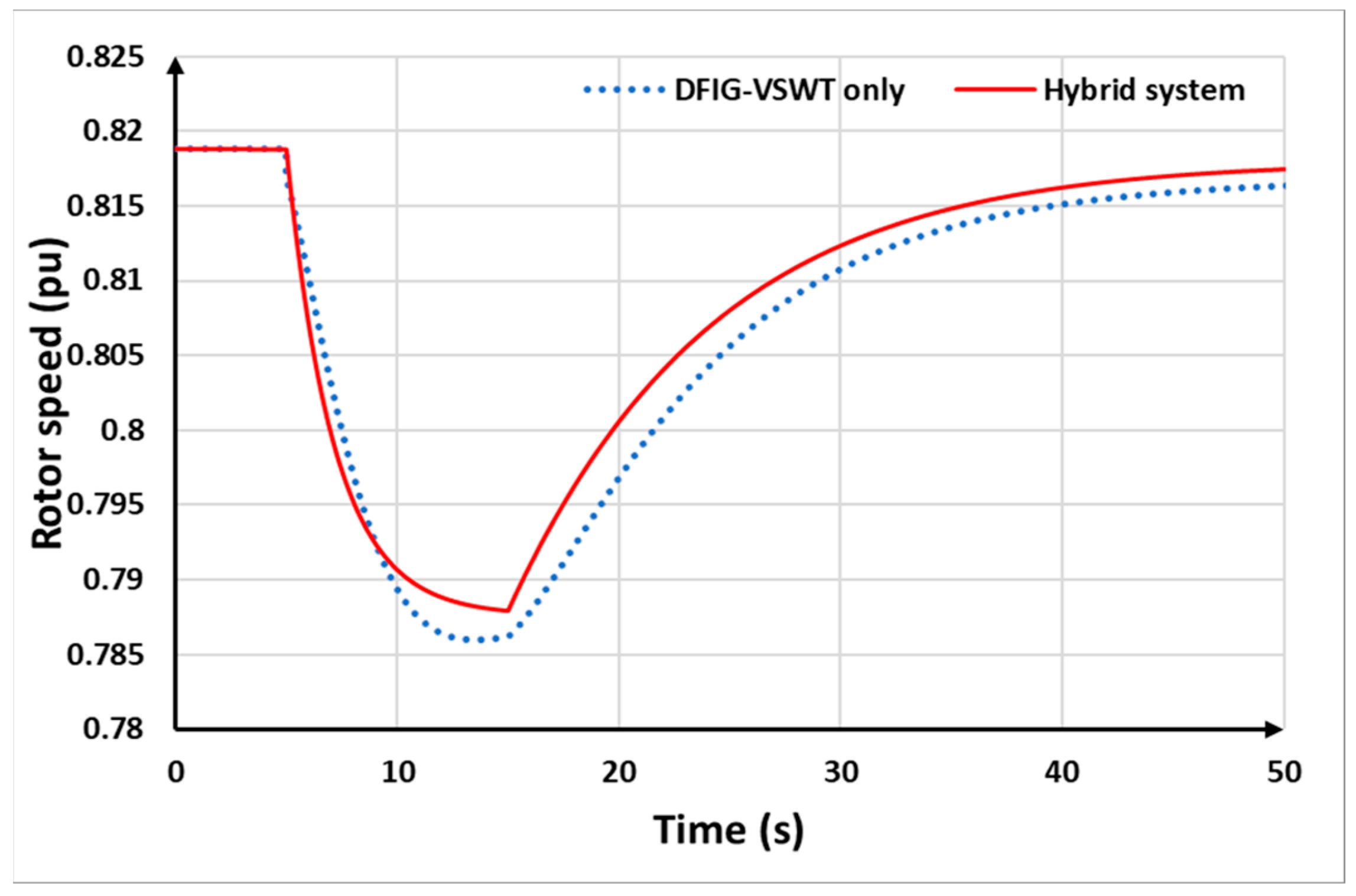
DFIG-VSWT rotor speed comparison in case 1.
Figure 15 illustrates the transient system frequency using the four control strategies. The corresponding frequency nadir and SFD values for each control technique are summarized in Table 5. Without any control strategy, the frequency nadir drops to 59.17 Hz. In the DFIG-VSWTs mode, the DFIG-based VSWTs provide reserved SKE through torque-based limit control, raising the frequency nadir to 59.33 Hz. Additionally, in the DFIG-VSWTs-only strategy, the system experiences an SFD, reducing the frequency to 59.38 Hz due to rotor speed recovery. With the BESS-only strategy, the frequency nadir is increased by 0.06 Hz compared to the DFIG-VSWTs-only strategy. The hybrid system strategy achieves a frequency nadir of 59.425 Hz, surpassing all other control strategies. Furthermore, with the auxiliary support from the BESSs, the hybrid system can avoid SFD.
Table 5.
Simulation results in case 1.
Figure 16 shows the supporting power output based on different methods. The supportive power of the hybrid system combines the supportive power of the DFIG-VSWTs and BESSs. Compared to the DFIG-VSWTs only and BESSs only, the hybrid system shows a larger area in supportive power, hence the hybrid system can support more supportive power in frequency regulation, which results in the highest frequency nadir among the strategies.
The comparison of the BESSs’ supportive power between the hybrid system and the BESS-only strategy is illustrated in Figure 17. It can be seen that, in both control strategies, the BESSs instantly provide reserved power for FFR at the beginning of the disturbance and then decrease to recover the reserved power afterward. In the hybrid system, the BESSs are controlled to provide auxiliary power to compensate for the power drop of the DFIG-VSWTs during rotor speed recovery.
Figure 18 shows the output power of the DFIG-VSWTs under different controls. At the beginning of the disturbance, both control approaches demonstrate that the DFIG-VSWTs can instantly provide SKE for frequency control. After that, the active power is reduced to recover the rotating speed. As shown in Figure 18, in the hybrid system, when the DFIG-VSWTs begin rotor speed recovery, the BESSs provide auxiliary power to compensate for the power drop. Therefore, the power drop of the DFIG-based VSWTs is improved from 0.218 p.u. for DFIG-VSWTs alone to 0.226 p.u. for the hybrid system. Furthermore, in the hybrid system, BESSs and DFIG-VSWTs share the supportive power, resulting in the DFIG-VSWTs providing less power compared to the DFIG-VSWTs-only strategy. As a result, in the hybrid system, the BESSs help prevent the DFIG-VSWTs from over-deceleration by taking on less of the power support burden. Thus, the rotor speed in the DFIG-VSWTs-only strategy is lower than in the hybrid system strategy, as observed in Figure 19.
6.2. Case 2: Constant Rated Wind Speed: Vw = 12 m/s
The disturbance of this scenario is identical to Case 1 but with a higher wind speed (12 m/s). The simulation results are summarized from Figure 20, Figure 21, Figure 22, Figure 23 and Figure 24.
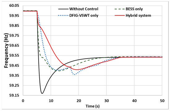
Figure 20.
System frequency in case 2.
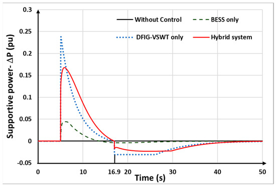
Figure 21.
Supportive power comparison in case 2.
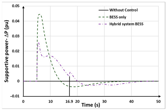
Figure 22.
Comparison of supportive power of BESSs in case 1.
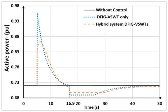
Figure 23.
Comparison of active power of DFIG-VSWTs in case 2.
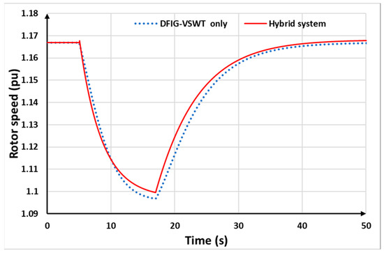
Figure 24.
DFIG-VSWT rotor speed comparison in case 2.
As the wind speed is 12 m/s, the rotor speed of DFIG-VSWTs is close to the maximum rotor speed, resulting in a higher reserved power compared to the wind speed at 8.4 m/s. Consequently, it becomes efficient for DFIG-VSWTs to provide frequency regulation.
The outcomes of frequency by different controls are shown in Figure 20, and the detailed results for frequency nadir and SFD are listed in Table 6. Using the proposed control strategy that combines DFIG-VSWTs with BESSs, the frequency nadir reaches 59.44 Hz, which is the highest value achieved among all examined control strategies. Furthermore, compared with the DFIG-VSWTs-only strategy, the hybrid system can avoid the SFD. The results clearly demonstrate the sustained effectiveness of the hybrid system in improving the frequency nadir and mitigating the adverse effects of SFDs, thereby highlighting its potential for enhancing overall system reliability.
Table 6.
Simulation results in case 2.
Figure 21 shows the supportive power in different control approaches. It can be seen that the hybrid system has a larger area in supportive power compared to other control strategies, hence the hybrid system can provide more power for frequency regulation, ensuring more effective improvement in frequency nadir and stabilization of system frequency during disturbances.
Figure 22 illustrates the comparison of the BESSs’ supportive power between the hybrid system and the BESS-only strategy. In both control strategies, the BESSs initially provide reserved power for FFR immediately at the beginning of the disturbance. This rapid response helps stabilize the system frequency. After this initial support, the BESSs gradually reduce their output to recover the reserved power. In the hybrid system, the BESSs are strategically controlled to provide auxiliary power to compensate for the power drop of the DFIG-VSWTs during their rotor speed recovery phase (at t = 16.9 s). This coordination ensures that the overall system maintains stability and the frequency remains within acceptable limits while the DFIG-VSWTs regain their operational speed.
Figure 23 further illustrates the efficacy of BESSs in regulating frequency within a hybrid system. By supplying supportive reserve power, BESSs contribute to enhancing the frequency nadir and mitigating the severity of the SFD. These findings underscore the crucial role of BESSs in maintaining grid stability during disruptive events such as SFDs. The results demonstrate the sustained effectiveness of the hybrid system in mitigating the adverse effects of SFDs, thereby highlighting its potential for enhancing overall system reliability.
Figure 23 shows the output power of the DFIG-VSWTs under different control strategies. Initially, both the DFIG-VSWTs-only and hybrid approaches allow the DFIG-VSWTs to provide instant SKE for frequency control. However, the power output from DFIG-VSWTs declines sharply after the frequency regulation process at 16.9 s, causing an SFD in system frequency. In the hybrid system, BESSs provide auxiliary power during the rotor speed recovery of the DFIG-VSWTs, resulting in a 0.01 p.u. higher power drop compared to the DFIG-VSWTs-only approach. Moreover, the BESSs share the burden in frequency control with DFIG-VSWTs, hence, reducing over-deceleration and maintaining higher rotor speeds, as shown in Figure 24. This collaboration enhances overall system stability and efficiency.
6.3. Case 3: Constant High Wind Speed: Vw = 14 m/s
Similar to case 2, only the wind speed is changed in this case (14 m/s). For wind speed at 14 m/s, the power output of DFIG-VSWTs reaches its rated value. Hence, the DFIG-VSWTs performance is limited effectively by utilizing the controlling the pitch angle control. If the DFIG-VSWTs provide extra power to regulate the system frequency drop, its power output will exceed the rated value. Therefore, at high wind speeds, only BESSs participate in frequency regulation.
Figure 25 depicts the system frequency response of various control models following a sudden loss of synchronous generators, resulting in an under-frequency fault. At this point, the DFIG-VSWTs have reached their maximum output power capacity; hence, they are unable to respond to frequency fluctuations. Consequently, the frequency nadir without control and utilizing DFIG-VSWTs alone strategies is lower than that of the BESSs and the proposed strategy. The frequency nadir is raised from 59.17 Hz to 59.4 Hz with FFR provided by BESSs. This highlights the limitations of DFIG-VSWTs in frequency regulation under these conditions and demonstrates the effectiveness of the BESSs, which enables the hybrid system to provide full FFR in this scenario. Figure 26 illustrates that only BESSs and the hybrid strategies are responsive to the regulation demand. Therefore, this case underscores the efficacy of the proposed coordinated control strategy in meeting frequency regulation requirements during high wind speed conditions. By dynamically coordinating with the BESS, the proposed strategy can enhance the system frequency and overcome the limitations of DFIG-VSWTs.
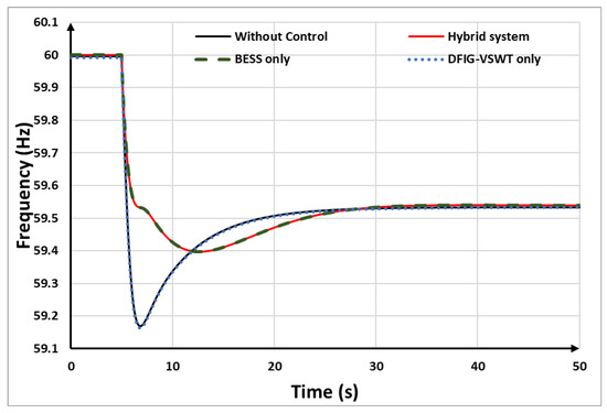
Figure 25.
System frequency in case 3.

Figure 26.
Supportive power comparison in case 3.
In conclusion, the hybrid system can provide full FFR in a wide- range of wind speed scenarios by combining the BESSs and DFIG-VSWTs. Furthermore, the appropriately sized BESS does not incur excessive investment costs. By distributing the output power reasonably between the BESS and DFIG-VSWTs, the hybrid system enhances the frequency regulation. This balanced approach optimizes both performance and cost-effectiveness, making the hybrid system a practicable solution for reliable frequency regulation.
7. Conclusions
This study highlights the rising utilization of wind power systems, which reduces overall system inertia and adversely affects the power system’s frequency regulation capability. This research investigates frequency control in DFIG-VSWTs and proposes a solution by integrating BESS into the wind farm. This paper also examines the optimal sizing of BESS to ensure economic viability while effectively providing frequency support in combination with DFIG-VSWTs. A SOC-adaptive droop control strategy is applied based on the SOC of the battery storage system, successfully preventing over-charging and over-discharging of the battery. Furthermore, this study identifies the coordinated output operation of the DFIG-VSWT and BESS hybrid system for each stage of primary frequency regulation across various wind speed scenarios. The effectiveness of the proposed approach is rigorously validated through numerous simulations using a MATLAB model of the wind-storage system. Comparative analyses with alternative control methods substantiates the efficacy of the proposed method in addressing the challenges posed by the evolving landscape of wind power systems. This research contributes valuable insights to the ongoing efforts to enhance power stability and performance amidst increasing renewable energy penetration, providing a robust framework for future implementations of hybrid energy systems. The findings underscore the importance of integrating advanced control strategies and optimal sizing in hybrid energy systems to maximize economic and operational benefits, paving the way for more resilient and efficient power grids.
Furthermore, the economic feasibility of a hybrid VSWT-BESS system can be researched more in the future, which includes detailed cost–benefit analyses. These analyses will refine economic models and guide practical implementation strategies for hybrid VSWT-BESS systems.
Author Contributions
Conceptualization, B.N.P.; methodology, B.N.P. and Y.-K.W.; data curation, B.N.P.; software, B.N.P.; formal analysis B.N.P.; investigation, B.N.P.; re-sources, B.N.P.; writing original draft preparation, B.N.P.; writing—review and editing, Y.-K.W. and M.-H.P.; validation, Y.-K.W. and M.-H.P.; Visualization, M.-H.P.; supervision, Y.-K.W.; funding acquisition Y.-K.W.; project administration, Y.-K.W. All authors have read and agreed to the published version of the manuscript.
Funding
This work was financially supported by both National Science and Technology Council (NSTC) of Taiwan under Grant NSTC 112-2221-E-194-005-MY2 and the Advanced Institute of Manufacturing with High-tech Innovations (AIM-HI) from the Featured Areas Research Center Program within the framework of the Higher Education Sprout Project by the Ministry of Education (MOE) in Taiwan.
Data Availability Statement
The original contributions presented in the study are included in the article, further inquiries can be directed to the corresponding author.
Conflicts of Interest
The authors declare no conflicts of interest.
References
- Lou, W.; Jin, Z.; Zhang, C.; Hou, A.; Wang, W.; Ding, L. Analysis of Primary Frequency Response Based on Overspeed and Pitch Control Reserve and Coordinated Control Strategy. In Proceedings of the 2023 IEEE International Conference on Power Science and Technology (ICPST), Kunming, China, 5–7 May 2023; pp. 193–198. [Google Scholar] [CrossRef]
- Fang, Q.; Chen, Z.; Zou, Y.; Zhou, L.; Yin, M. Improved Stepwise Inertial Control for Wind Turbines Considering Frequency Response of Synchronous Generators. In Proceedings of the 2021 China Automation Congress (CAC), Beijing, China, 22–24 October 2021; pp. 2587–2593. [Google Scholar] [CrossRef]
- Gao, W.; Wu, Z.; Wang, J.; Gu, S. A review of inertia and frequency control technologies for variable speed wind turbines. In Proceedings of the 2013 25th Chinese Control and Decision Conference (CCDC), Guiyang, China, 25–27 May 2013; pp. 2527–2533. [Google Scholar] [CrossRef]
- Morren, J.; Pierik, J.; de Haan, S.W.H. Inertial response of variable speed wind turbines. Electr. Power Syst. Res. 2006, 76, 980–987. [Google Scholar] [CrossRef]
- Morren, J.; de Haan, S.W.H.; Kling, W.L.; Ferreira, J.A. Wind Turbines Emulating Inertia and Supporting Primary Frequency Control. IEEE Trans. Power Syst. 2006, 21, 433–434. [Google Scholar] [CrossRef]
- Ramtharan, G.; Jenkins, N.; Ekanayake, J.B. Frequency support from doubly fed induction generator wind turbines. IET Renew. Power Gener. 2007, 1, 3. [Google Scholar] [CrossRef]
- Xue, Y.; Tai, N. Review of contribution to frequency control through variable speed wind turbine. Renew Energy 2011, 36, 1671–1677. [Google Scholar] [CrossRef]
- Abdeen, M.; Sayyed, M.; Dominguez-Garcia, J.L.; Kamel, S. Supplemental Control for System Frequency Support of DFIG-Based Wind Turbines. IEEE Access 2022, 10, 69364–69372. [Google Scholar] [CrossRef]
- Attya, A.B.; Dominguez-Garcia, J.L.; Anaya-Lara, O. A review on frequency support provision by wind power plants: Current and future challenges. Renew. Sustain. Energy Rev. 2018, 81, 2071–2087. [Google Scholar] [CrossRef]
- Miao, L.; Wen, J.; Xie, H.; Yue, C.; Lee, W.J. Coordinated Control Strategy of Wind Turbine Generator and Energy Storage Equipment for Frequency Support. IEEE Trans. Ind. Appl. 2015, 51, 2732–2742. [Google Scholar] [CrossRef]
- Tan, J.; Zhang, Y. Coordinated Control Strategy of a Battery Energy Storage System to Support a Wind Power Plant Providing Multi-Timescale Frequency Ancillary Services. IEEE Trans. Sustain. Energy 2017, 8, 1140–1153. [Google Scholar] [CrossRef]
- Wu, Y.K.; Yang, W.H.; Hu, Y.L.; Dzung, P.Q. Frequency regulation at a wind farm using time-varying inertia and droop controls. In IEEE Transactions on Industry Applications; Institute of Electrical and Electronics Engineers Inc.: New York, NY, USA, 2019; pp. 213–224. [Google Scholar] [CrossRef]
- Ullah, N.R.; Thiringer, T.; Karlsson, D. Temporary primary frequency control support by variable speed wind turbines—Potential and applications. IEEE Trans. Power Syst. 2008, 23, 601–612. [Google Scholar] [CrossRef]
- Yang, D.; Kim, J.; Kang, Y.C.; Muljadi, E.; Zhang, N.; Hong, J.; Song, S.H.; Zheng, T. Temporary Frequency Support of a DFIG for High Wind Power Penetration. IEEE Trans. Power Syst. 2018, 33, 3428–3437. [Google Scholar] [CrossRef]
- Hansen, A.D.; Altin, M.; Margaris, I.D.; Iov, F.; Tarnowski, G.C. Analysis of the short-term overproduction capability of variable speed wind turbines. Renew Energy 2014, 68, 326–336. [Google Scholar] [CrossRef]
- Das, K.; Altin, M.; Hansen, A.D.; Sørensen, P.E. Inertia Dependent Droop Based Frequency Containment Process. Energies 2019, 12, 1648. [Google Scholar] [CrossRef]
- Lee, J.; Muljadi, E.; Sørensen, P.; Kang, Y.C. Releasable kinetic energy-based inertial control of a DFIG wind power plant. IEEE Trans. Sustain. Energy 2016, 7, 279–288. [Google Scholar] [CrossRef]
- El Itani, S.; Annakkage, U.D.; Joos, G. Short-term frequency support utilizing inertial response of DFIG wind turbines. In Proceedings of the IEEE Power and Energy Society General Meeting, Detroit, MI, USA, 24–28 July 2011. [Google Scholar] [CrossRef]
- Xu, Y.; Wang, H. Torque Limit-Based Inertial Control of a DFIG for Rapid Frequency Stabilization. Front. Energy Res. 2021, 9, 788989. [Google Scholar] [CrossRef]
- Kang, M.; Kim, K.; Muljadi, E.; Park, J.-W.; Kang, Y.C. Frequency Control Support of a Doubly-Fed Induction Generator Based on the Torque Limit. IEEE Trans. Power Syst. 2016, 31, 4575–4583. [Google Scholar] [CrossRef]
- Wu, Z.; Gao, D.W.; Zhang, H.; Yan, S.; Wang, X. Coordinated Control Strategy of Battery Energy Storage System and PMSG-WTG to Enhance System Frequency Regulation Capability. IEEE Trans. Sustain. Energy 2017, 8, 1330–1343. [Google Scholar] [CrossRef]
- Choi, J.W.; Heo, S.Y.; Kim, M.K. Hybrid operation strategy of wind energy storage system for power grid frequency regulation. IET Gener. Transm. Distrib. 2016, 10, 736–749. [Google Scholar] [CrossRef]
- Tang, Y.; Yang, C.; Yan, Z.; Xue, Y.; He, Y. Coordinated Control of a Wind Turbine and Battery Storage System in Providing Fast-Frequency Regulation and Extending the Cycle Life of Battery. Front. Energy Res. 2022, 10, 927453. [Google Scholar] [CrossRef]
- Ochoa, D.; Martinez, S. Fast-Frequency Response Provided by DFIG-Wind Turbines and its Impact on the Grid. IEEE Trans. Power Syst. 2017, 32, 4002–4011. [Google Scholar] [CrossRef]
- Chen, S.; Zhang, T.; Gooi, H.B.; Masiello, R.D.; Katzenstein, W. Penetration Rate and Effectiveness Studies of Aggregated BESS for Frequency Regulation. IEEE Trans. Smart Grid. 2016, 7, 167–177. [Google Scholar] [CrossRef]
- Kim, H.S.; Hong, J.; Choi, I.S. Implementation of distributed autonomous control based battery energy storage system for frequency regulation. Energies 2021, 14, 2672. [Google Scholar] [CrossRef]
- Shepherd, C.M. “Design of Primary and Secondary Cells. J. Electrochem. Soc. 1965, 112, 657. [Google Scholar] [CrossRef]
- Shim, J.W.; Verbic, G.; Zhang, N.; Hur, K. Harmonious Integration of Faster-Acting Energy Storage Systems into Frequency Control Reserves in Power Grid with High Renewable Generation. IEEE Trans. Power Syst. 2018, 33, 6193–6205. [Google Scholar] [CrossRef]
- Díaz-González, F.; Hau, M.; Sumper, A.; Gomis-Bellmunt, O. Participation of wind power plants in system frequency control: Review of grid code requirements and control methods. Renew. Sustain. Energy Rev. 2014, 34, 551–564. [Google Scholar] [CrossRef]
- Shim, J.W.; Verbic, G.; Kim, H.; Hur, K. On droop control of energy-constrained battery energy storage systems for grid frequency regulation. IEEE Access 2019, 7, 166353–166364. [Google Scholar] [CrossRef]
- Rebello, E.; Watson, D.; Rodgers, M. Practical aspects and results—Providing secondary frequency regulation from a single Type 4 wind turbine and a battery storage system. In Proceedings of the 2021 IEEE Green Technologies Conference (GreenTech), Denver, CO, USA, 7–9 April 2021; pp. 105–111. [Google Scholar] [CrossRef]
- Zhao, X.; Lin, Z.; Fu, B.; Gong, S. Research on frequency control method for micro-grid with a hybrid approach of FFR-OPPT and pitch angle of wind turbine. Int. J. Electr. Power Energy Syst. 2021, 127, 106670. [Google Scholar] [CrossRef]


Disclaimer/Publisher’s Note: The statements, opinions and data contained in all publications are solely those of the individual author(s) and contributor(s) and not of MDPI and/or the editor(s). MDPI and/or the editor(s) disclaim responsibility for any injury to people or property resulting from any ideas, methods, instructions or products referred to in the content. |
© 2024 by the authors. Licensee MDPI, Basel, Switzerland. This article is an open access article distributed under the terms and conditions of the Creative Commons Attribution (CC BY) license (https://creativecommons.org/licenses/by/4.0/).