Article

Study on the Operation Optimization of Medium-Depth U-Type Ground Source Heat Pump Systems

1
CTG Wuhan Science and Technology Innovation Park, China Three Gorges Corporation, Wuhan 430010, China
2
China Yangtze Power Co., Ltd., Wuhan 430010, China
3
School of Environmental Science and Engineering, Huazhong University of Science and Technology, Wuhan 430074, China
*
Authors to whom correspondence should be addressed.
Energies 2024, 17(13), 3184; https://doi.org/10.3390/en17133184
Submission received: 24 May 2024 / Revised: 20 June 2024 / Accepted: 24 June 2024 / Published: 28 June 2024

Abstract

:
Deep geothermal energy is a sustainable and renewable spacing heating source. Although many studies have discussed the design optimization of deep borehole systems, few have accomplished optimization and in-depth analysis of system operation control. In this study, an analytical model of the U-type deep borehole heat exchanger is proposed, and the average relative error between the simulated outlet temperatures and experimental data is −3.2%. Then, this paper presents an integrated model for the operation optimization study of the U-type deep-borehole ground source heat pump system. The optimal control of flow rate is adopted to match the variation in heating load. Compared with the constant-flow rate (110 m3/h) operation mode, the variable flow rate method reduces the power consumption of the heat pump and circulating pump by 22.1%, from 288,423 kW·h to 224,592 kW·h, during 2112 h of operation. In addition, the system has a larger RHS and COP when the thermal conductivity of the backfill material increases. When the borehole depth increases by 200 m from 2300 m, the energy consumption of the circulating pump will drop from 85,844 kW·h to 56,548 kW·h. The COP of the heat pump unit will decrease approximately linearly as the heating load increases, and the total power consumption will increase accordingly. This work can provide guidance for the design and optimization of U-shaped GSHP systems.

1. Introduction

Geothermal energy is an important renewable energy source for power generation [1], spacing cooling/heating [2] and some additional preheating processes [3]. The traditional ground source heat pump (GSHP) systems typically utilize geothermal energy from depths shallower than 200 m, applicable for both cooling and heating [4]. Although this technology is relatively mature and widely employed, shallow GSHP systems [5] encounter limitations due to their small temperature differentials, necessitating substantial land area and soil thermal balance maintenance [6]. In scenarios where the thermal load of buildings significantly exceeds the cooling load, shallow GSHP systems often struggle to meet long-term heating demands, and prolonged heat extraction leads to lowered soil temperatures, resulting in decreased operational efficiency [7].
In comparison to shallow GSHP systems, mid-deep GSHP systems [8], with borehole depths typically ranging from 2000 to 3000 m, exhibit higher bottom temperatures, significantly enhancing their heat extraction capabilities. And it should be noted that the U-type ground heat exchanger in this study is referring to a much deeper-buried tube instead of a shallow single-U system. These systems operate more efficiently and stably but are solely suitable for heating purposes, particularly in colder regions [9]. With the continuous exploitation of resources, more and more natural gas or oil wells have been abandoned [10]. These wells contain abundant geothermal energy, and harmful gases may leak if they are improperly sealed or left open [11]. In recent years, there have been cases of using abandoned wells to develop mid-deep geothermal energy in many countries [12,13,14], which can reduce drilling costs and promote the application of mid-deep borehole heat exchangers. There are coaxial and U-type DBHEs applied in engineering, but it should be noted that the deep U-type BHE differs from the shallow U-tube borehole [15]. Zhang et al. [16] examined the differences in thermal performance between coaxial and U-type DBHE. The results show that the nominal heat extraction of U-type deep BHE is usually higher than 1000 kW, which is more than twice as much as that of coaxial pipe deep BHE. A similar work was also presented by Brown et al. [17], in which both hydraulic and thermal features were compared in numerical way. In terms of the long-term operation and thermal recovery performance for U-type BHE, the results show that the thermal recovery rate of deep rock and soil is over 91.2% after an eight-month thermal recovery period [18].
In recent years, to enhance the utilization efficiency of mid-deep geothermal energy, a U-type borehole heat exchanger has been developed in the Guanzhong Basin of China [19,20]. As illustrated in Figure 1, this borehole heat exchanger features a U-shaped configuration designed for mid-deep applications. In this design, the circulating fluid flows through a descending pipe, horizontal pipe, and ascending pipe successively, reducing the risk of thermal short-circuiting compared to conventional borehole heat exchangers. Additionally, the horizontal pipes at the bottom increase the heat exchange area between the circulating fluid and the high-temperature rock, resulting in enhanced heat extraction capabilities [16,21]. However, current research on mid-deep U-shaped borehole GSHP systems predominantly relies on numerical models, facing challenges such as high computational requirements and lengthy calculation time [22,23].
The U-type deep borehole heat exchanger (DBHE) differs from the coaxial deep borehole heat exchanger in that it consists of two deep boreholes connected in a deep layer with a horizontal tube. To understand the thermal performance of this U-type deep borehole heat exchanger, researchers examined different efficient models including numerical or analytical simulation. Chen et al. [23] established the geometry of the U-type DBHE and solved the heat transfer process using OpenGeoSys. The numerical model was verified through comparison with data from the study by Ramey Jr et al. [24]. In addition to using existing commercial software or codes, the pursuit-solving method of the heat transfer governing equation used by Zhang et al. [21] is an effective way. In order to obtain an analytical model of this U-type DBHE, some researchers [25,26,27,28] adopted similar methods of separation into two vertical boreholes and one horizontal borehole and used the superposition method for a finial ground temperature solution. Moreover, if the groundwater flow condition is considered, the moving line method should be integrated into the solution [25].
The Taguchi method is a commonly used method for multi-factor analysis and the simple optimization of a U-type DBHE system. Jiang et al. [29] mainly considered the influence of ground conditions, such as thermal conductivity, geothermal gradient, specific heat capacity, etc. Huang et al. [30,31] explored more influencing parameters for the U-type DBHE, and Analysis of Variance (ANOVA) was used to quantify the percentage contribution of each factor. Instead of a simple U-type heat exchanger, Wang et al. [32] investigated a type of multi-branch U-type DBHE system. It was found that for a 2000 m long horizontal well, increasing the number of branches is conducive to increasing the heat production capacity of the geothermal system, and the total power shows a linear relationship with the number of branches.
Considerable research efforts have been devoted globally to mid-deep borehole GSHP systems, focusing primarily on the performance of borehole heat exchangers and analyzing the energy efficiency of heat pump systems. Nevertheless, research on the performance coupling between mid-deep GSHP systems and buildings is relatively scarce. The novelty here is in establishing an analytical model for mid-deep U-shaped BHEs and proposing an operation optimization model coupling GSHP systems with buildings. For the latter, constant inlet temperature and variable flow rate are proposed to match the change of heating load. The energy saving performance of the optimization model is proved by comparing it with the constant-flow-rate mode. This paper also analyses the effect of three parameters, including backfill material, borehole length and heating load, on the optimization results.

2. Method

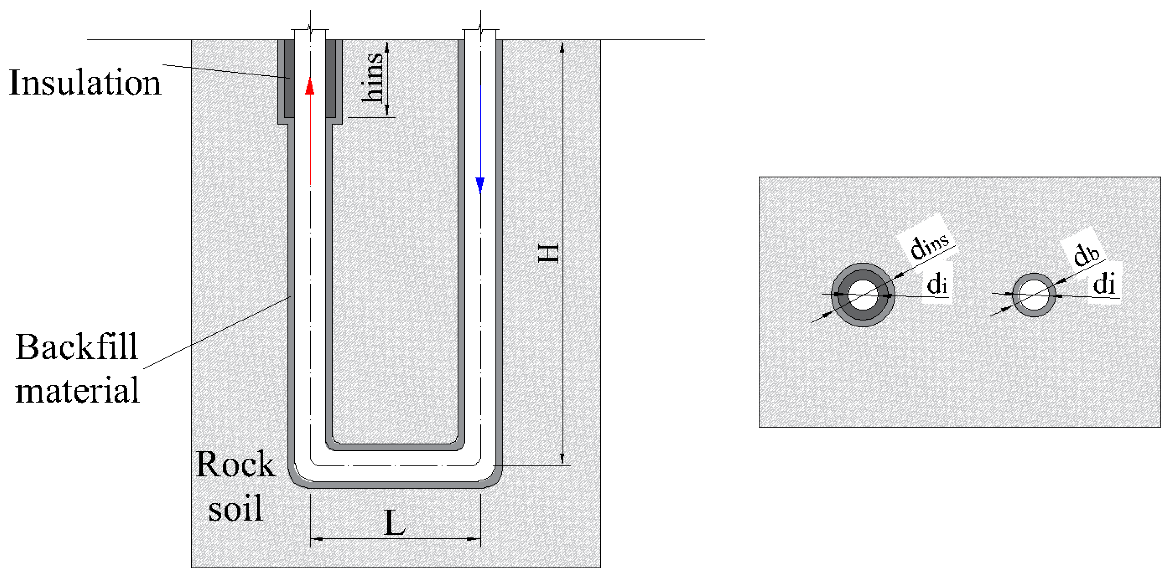
2.1. Basic Assumptions

To simplify the heat transfer problem, this study regularizes the geometry of the U-shaped buried pipe heat exchanger. The heat transfer process between the circulating fluid inside the underground pipes and the surrounding rock and soil is complex, involving heat convection between the fluid and the pipe, heat conduction between the inner and outer walls of the pipe, heat conduction between the outer wall of the pipe and the backfill material, heat conduction between the backfill material and the borehole wall, and heat conduction between the borehole wall and the rock and soil. To simplify the heat transfer model and facilitate subsequent research and analysis, the following assumptions are made:
(1)
Neglect the slope of the horizontal pipe section, and consider the initial soil temperature based on the geothermal gradient;
(2)
Ignore the heat conduction in the depth direction inside the borehole;
(3)
At the same depth, the temperatures of the underground pipe, backfill material, and circulating fluid are equal;
(4)
Do not consider the effects of water evaporation, diffusion, condensation, and groundwater seepage on the heat conduction process in the rock and soil;
(5)
Each layer of rock and soil has constant and uniform thermal properties, unaffected by temperature.

2.2. Mathematical Model

In this study, the underground heat transfer process of the deep U-shaped buried pipe heat exchanger is divided into two parts, inside and outside the borehole, and energy control equations for the rock and soil and the circulating fluid are established. Through their coupling, an analytical solution model for the heat transfer analysis of the U-shaped buried pipe heat exchanger is established, realizing the simulation and analysis of the entire underground temperature field evolution process.
For boreholes with uneven heat flux density, applying the conventional finite line heat source model is not feasible. Based on this, Luo et al. [33] proposed a segmented finite line heat source model. Consistent with the traditional FLS method, a virtual line heat source with a heat extraction rate of −q is symmetrically set with the horizontal plane as the mirror, dividing the actual line heat source and the virtual line heat source into n segments, including 2 × n1 vertical segments and n2 horizontal segments, with uniform heat flux density distribution in each segment. Furthermore, during the operation of the buried pipe heat exchanger, the heat flux density changes dynamically. Based on the superposition principle, the excess temperatures generated at the τ moment and the point (x,0,z) in the ascending, horizontal, and descending sections are as follows:
θ 1 ( x , z , τ ) = j = 1 N i = 1 n 1 q i , N j + 1 8 π λ j e x 2 4 a j Δ τ ( - erf ( z i Δ z 2 a τ ) + erf ( z ( i 1 ) Δ z 2 a τ ) + erf ( z + ( i 1 ) Δ z 2 a τ ) - erf ( z + i Δ z 2 a τ ) )
θ 2 ( x , z , τ ) = j = 1 N i = n 1 + 1 n 1 + n 2 q i , N j + 1 8 π λ j ( e ( z H ) 2 4 a j Δ τ + e ( z + H ) 2 4 a j Δ τ ) × ( - erf ( x ( i n 1 ) Δ x 2 a τ ) - erf ( x z ( i n 1 1 ) Δ x 2 a τ ) )
θ 3 ( x , z , τ ) = j = 1 N i = n 1 + n 2 + 1 n q i , N j + 1 8 π λ j e ( x L ) 2 4 a j Δ τ ( - erf ( z ( n i + 1 ) Δ z 2 a τ ) + erf ( z ( n i ) Δ z 2 a τ ) + erf ( z + ( n i ) Δ z 2 a τ ) - erf ( z + ( n i + 1 ) Δ z 2 a τ ) )
where H and L are the lengths of the vertical and horizontal boreholes, respectively, m; q is the heat extraction per unit length of the borehole, W/m; λ is the thermal conductivity of the rock and soil medium, W/(K·m); Δτ is the time step, s; Δx and Δz are the lengths of the horizontal and vertical segments, m; a is the thermal diffusivity of the rock and soil, m2/s; and τ is the operation time, s.
For the heat transfer process inside the borehole, the heat transfer of the fluid inside the pipe is considered a one-dimensional problem, and the U-shaped pipe is divided into n segments. Subscripts 1, 2, and 3 represent the ascending pipe, horizontal pipe, and descending pipe, respectively. The energy equation of the circulating fluid in the U-shaped pipe can be expressed as follows:
  C i T f , i τ = T b , i T f , i R b , i m c f T f , i z i = 1 , 3
  C i T f , i τ = T b , i T f , i R b , i c f T f , i x m c f T f , i x i = 2
In the equation, Tf,i is the temperature of the circulating fluid, °C; Tb,i is the temperature of the borehole wall, °C; m is the mass flow rate of the circulating fluid, kg/s; and Ci is the sum of the thermal capacitance of materials per unit length inside the borehole, J/(kg·K).
Based on the heat transfer equations of the soil and fluid, simulation can be carried out by compiling computer programs. The fluid temperature at time k + 1 can be determined using the fluid temperature and the borehole wall temperature at time k. Next, the heat flow along the borehole can be calculated, followed by calculating the wall temperature at time k + 1 using Equations (1)–(3). Consequently, the evolution of the underground temperature field can be simulated.

2.3. Model Validation
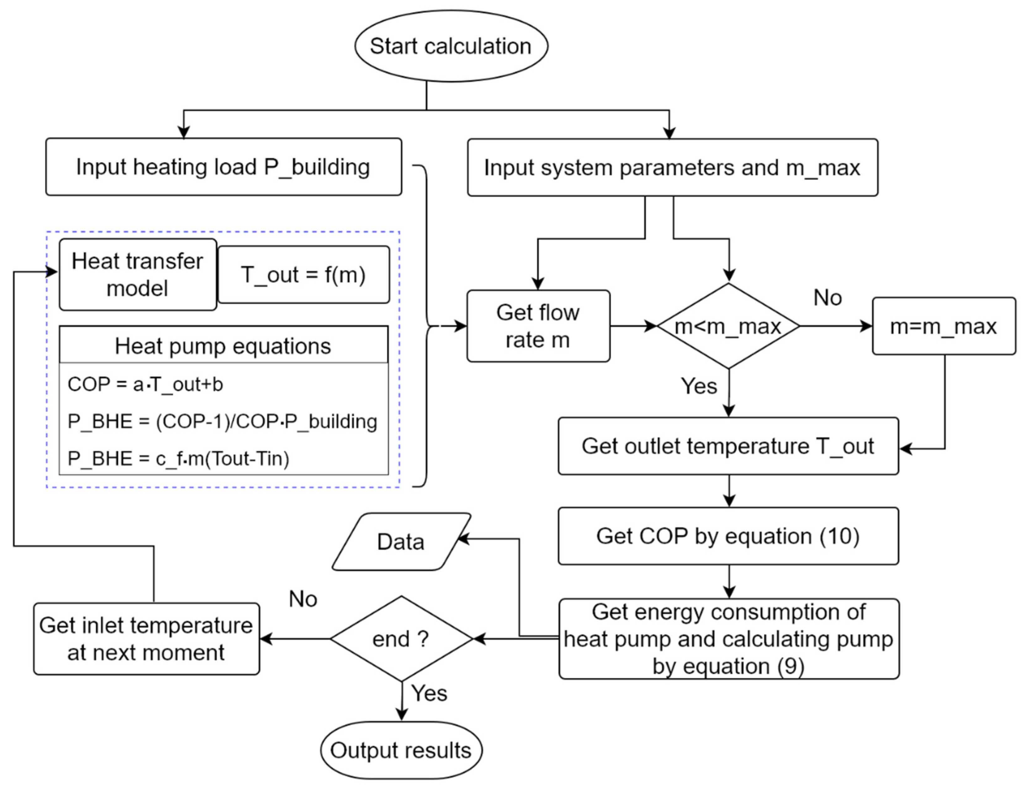
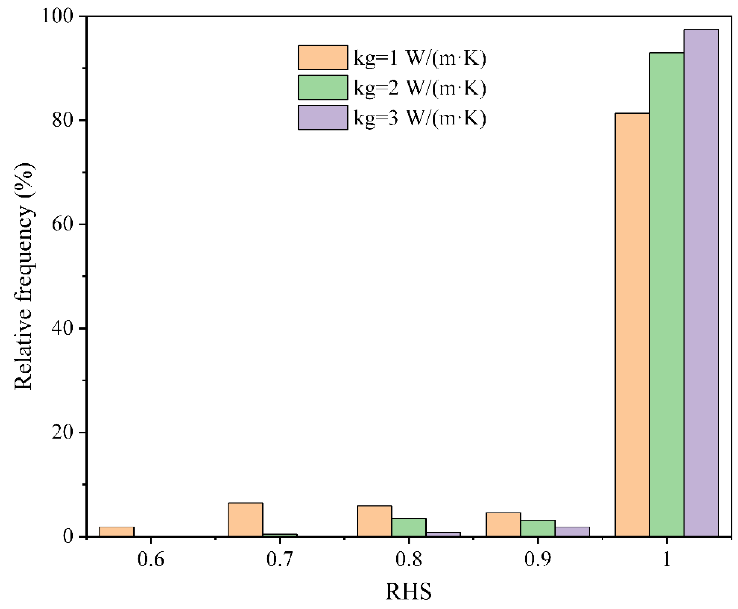
This section validates the established mathematical model by comparing simulation results with experimental measurements reported in the literature. The experimental data were sourced from Li et al. [34], derived on 28 February 2017, starting at 10:00 and concluding after 72 h. The inlet water temperature was maintained at 19.5 °C with a flow rate of 46.5 m3/h. Table 1 presents the basic model parameters. The ground temperature gradient was 2.62 °C/100 m, with initial temperatures of soil and water being equal. Based on these conditions, the mathematical model was employed to simulate the outlet fluid temperature over 72 h and the results were compared with experimental data [34], as shown in Figure 2. Initially, the maximum relative error in the outlet temperature was −18.2%, which was attributed to neglecting the influence of pipe walls and the backfill material’s thermal capacitance. After 9 h of operation, the simulation results stabilized and exhibited consistent trends with experimental data, showing good agreement with relative errors ranging from −4% to −2%, and the average value of relative error was −3.2%.

3. Results

In the design process of ground source heat pump systems with buried pipes, the drilling depth is typically calculated under the premise of meeting the most unfavorable conditions. In practical operation, the real-time heat load of most buildings often falls below the design value. In this chapter, we propose a variable-flow operation model for medium-depth U-type ground source heat pump systems. This model comprehensively considers the dynamic heat load of terminal buildings and the dynamic heat exchange process on the ground source side. It adopts a variable-flow method to match the dynamic changes in building heat load, while also reducing the energy consumption of the ground source loop pump. This enables the calculation of water flow based on known building heat load, achieving optimization of ground source heat pump system operation. The calculation process is illustrated in Figure 3. Assuming a fixed inlet temperature, the program calculates the required flow rate to match the heating load using Equations (1)–(7). If the flow rate is greater than the maximum value, it is necessary to further reduce the outlet temperature of the heat pump, i.e., the inlet temperature of the BHE at the next moment. The coefficient of performance (COP) of the heat pump unit is calculated by the following equation:
C O P = P b u i l d i n g P hp
where Pbuilding is the building heat load, kW, and Php is the energy consumption of the heat pump unit, kW.
Considering that the heating capacity of the heat pump unit is the sum of its power consumption and the heat absorbed by the ground source heat exchanger, Equation (6) can be expressed as follows:
P B H E = C O P 1 C O P P b u i l d i n g
The energy consumption of the circulating water pump is related to the drilling structure and the flow rate of the circulating fluid [35], and can be calculated by the following equation:
P cp = q f η f L D h ρ f v 2 2
where qf is the water flow rate, m3/s; η is the efficiency of the circulating water pump (assumed to be 70%); f is the Darcy friction factor; L is the length of the borehole, m; Dh is the hydraulic diameter of the pipeline, m; and v is the flow velocity, m/s. The total power consumption of the heat pump unit and the circulating water pump can be represented as follows:
W = [ P h p ( τ ) + P c p ( τ ) ] d τ
The COP of the heat pump unit is related to the outlet temperature of the ground source heat exchanger and the terminal temperature of the building heating, and is linearly related to the outlet temperature of the ground source [36,37], as expressed by the following equation:
C O P = a · T o u t + b
In this study, the temperature of hot water for floor heating is set to 35 °C, and then a = 0.083 and b = 3.925.
Figure 4 shows the heat load of an office building from 1 December of one year to 28 February of the next year. Based on this, simulation calculations of the variable-flow operation of ground source heat pump systems were conducted, and the results are shown in Figure 5 and Figure 6. In the following analysis, the concept of Heating Assurance Rate (RHS) is used, which is the ratio of system heating capacity to building heat load. From the figures, this operation mode prioritizes controlling fluid flow. If the fluid flow is still insufficient to meet the heating demand of the building when it reaches its maximum value, it is necessary to further reduce the outlet temperature of the heat pump, i.e., the inlet temperature of the ground source at the next moment, but the inlet temperature must be maintained above 5 °C. The variation of circulating fluid flow with time is consistent with the change in heating load overall. When the building heat load decreases, the fluid flow also decreases, thereby reducing the system’s heating capacity and avoiding energy waste. During the simulation operation, the inlet temperature of the ground source shows a decreasing trend, while the outlet temperature fluctuates with time. When the building heat load is low, the required fluid flow decreases, resulting in a higher temperature difference between the inlet and outlet. Although the inlet temperature of BHE is lower, its outlet temperature is higher than that of constant-flow-rate mode, resulting in higher COP of the heat pump. As shown in Figure 6, the average COP is 5.14, which is higher than the value of 4.99 with constant flow rate. Therefore, the heat extraction of BHE will be slightly higher. Under variable-flow operation, the average RHS during the simulation operation period is 98.8%. Considering similar RHS values, the fluid flow rate under fixed-flow operation is set to 110 m3/h. Compared with this, variable-flow operation reduces the power consumption of the heat pump unit from 171,090 kW·h to 168,043 kW·h, and the circulating pump power consumption from 117,332 kW·h to 56,548 kW·h, resulting in a total reduction in power consumption of 22.1%. The variable-flow-rate operation is realized by frequency conversion, which has no influence on the longevity of the system.

4. Discussion

The thermal conductivity of the backfill material was set to 1.0, 2.0, and 3.0 W/(m·K), respectively. After simulating the operation of the ground source heat pump system for 2112 h, the relative frequency distribution chart of the RHS and the variation curve of the unit COP over time are shown in Figure 7 and Figure 8, respectively. As the thermal conductivity of the backfill material decreases, the occurrence time of insufficient heating advances, and the minimum value of the RHS also decreases. When the thermal conductivity increases, the COP of the heat pump unit and the heating guarantee rate also increase accordingly. For instance, when the thermal conductivity increases from 1.0 W/(m·K) to 3.0 W/(m·K), the average RHS increases from 95.7% to 99.6%, and the average COP increases from 4.953 to 5.233.
Figure 9 and Figure 10 illustrate the distribution of RHS and the variation in the heat pump unit COP over time with different lengths of vertical pipe segments during the simulation period. With the increase in the length of the vertical pipe segment, both RHS and COP increase, indicating that increasing the drilling depth is beneficial for improving the heat extraction performance of the system. When the pipe length increases from 2300 m to 2500 m, the average RHS increases from 95.7% to 98.8%, and the heat pump unit COP increases from 4.929 to 5.135. Increasing the length of the vertical pipe segment enhances the heat extraction capacity of the ground loop, thereby reducing the circulation flow rate and further decreasing the power consumption of the circulation pump. For example, when the pipe length increases from 2300 m to 2500 m, the power consumption of the circulation pump decreases from 85,844 kW·h to 56,548 kW·h, while the power consumption of the heat pump unit increases from 166,013 kW·h to 168,043 kW·h. Consequently, the total power consumption decreases from 251,858 kW·h to 224,592 kW·h, while ensuring the economic efficiency of the system. Therefore, it is feasible to appropriately increase the drilling depth to improve system performance.
The building load relative percentages were set at 80%, 90%, 100%, 110%, and 120%, respectively, to study the system performance under different heat loads, as shown in Figure 11 and Figure 12. As the building heat load decreases, the heat extraction capacity of the ground loop heat exchanger also decreases, and the heating guarantee rate increases to a certain extent. When the building heat load decreases by 20%, during the simulation period, the average heat extraction capacity of the ground loop heat exchanger decreases from 320 kW to 265 kW, a reduction of 17.2%. As the building heat load increases, the COP of the heat pump unit gradually decreases, while the energy consumption of the heat pump and circulation pump gradually increases. This is because with an increase in heat load, the demand for heat extraction from the ground loop heat exchanger increases, causing the surrounding rock and soil temperature to decrease more rapidly, resulting in a lower outlet temperature of the circulating fluid and consequently decreasing the COP of the unit.

5. Conclusions and Outlook

5.1. Conclusions

This paper proposes an analytical solution model for the heat transfer analysis of U-shaped ground heat exchangers, and it is validated by experimental data in the reference. Additionally, a variable-flow operation model, which comprehensively considers the dynamic heating load and heat transfer process of BHEs, is established for the operation optimization research of ground source heat pump systems with known building thermal loads. The conclusions drawn are as follows:
  • An analytical solution heat transfer model for medium-depth U-type ground heat exchangers is established, and the simulation results align well with experimental data with an average relative error of −3.2%.
  • Operating the system with variable fluid flow can reduce energy consumption. When the heating load decreases, the flow rate becomes smaller and the temperature difference between inlet and outlet will increase. Compared to constant flow operation, the average COP of the heat pump increases from 4.99 to 5.12 over a simulated runtime of 2112 h. In addition, the power consumption of the heat pump decreases from 171,090 kW·h to 168,043 kW·h, and the circulating pump power consumption decreases from 117,332 kW·h to 56,548 kW·h, with the total power consumption decreasing by 22.1%.
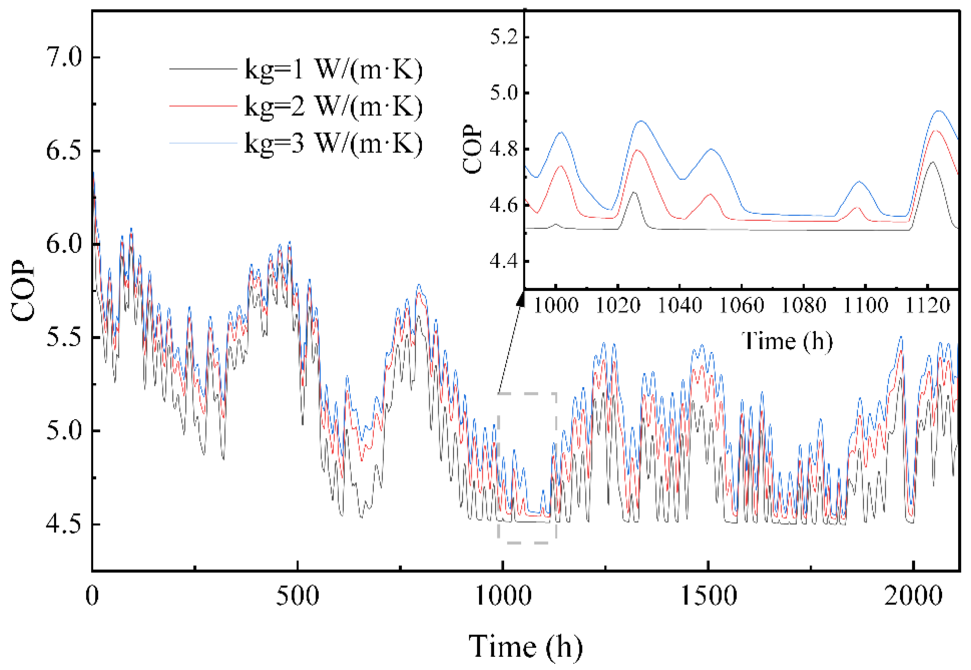
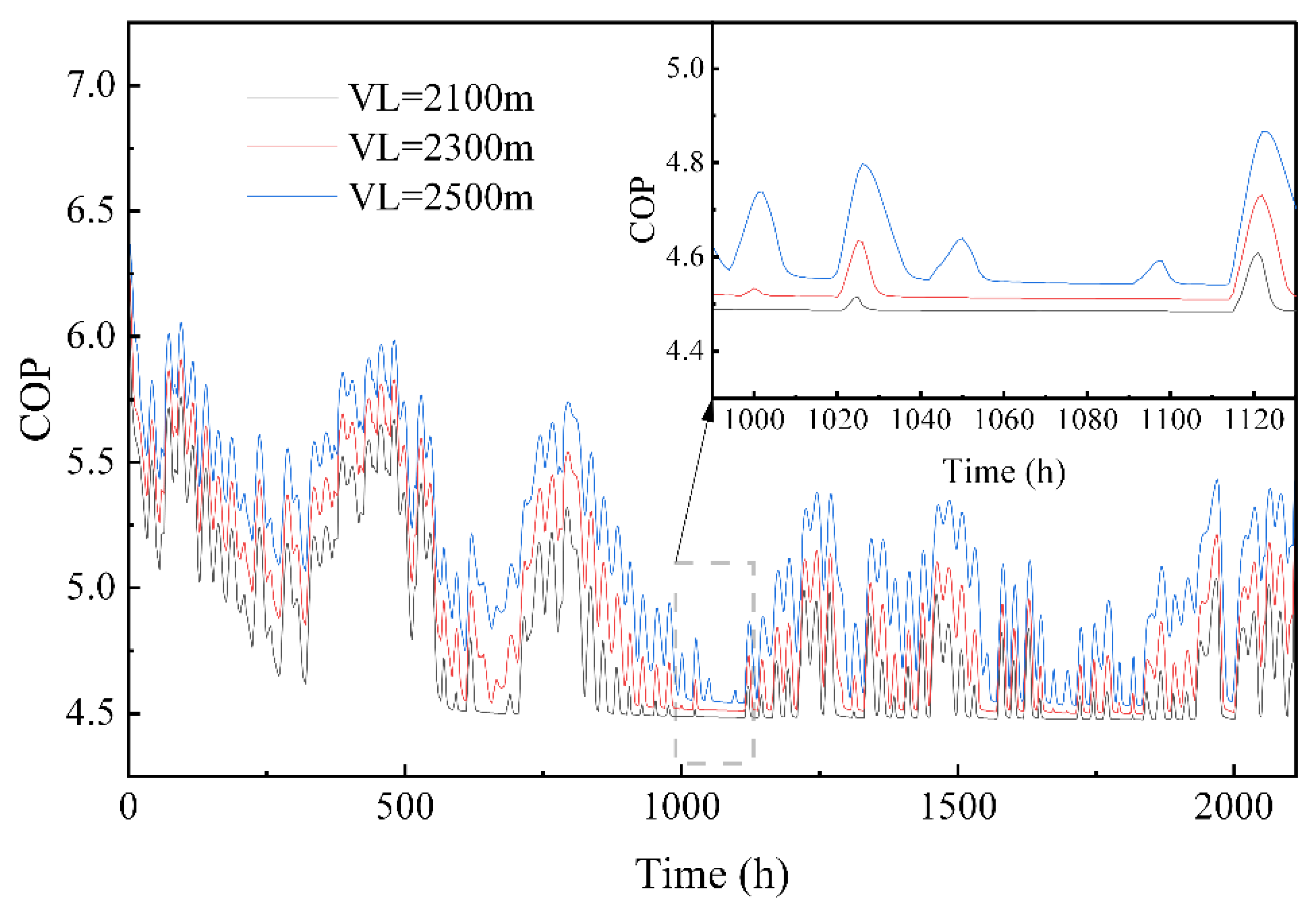
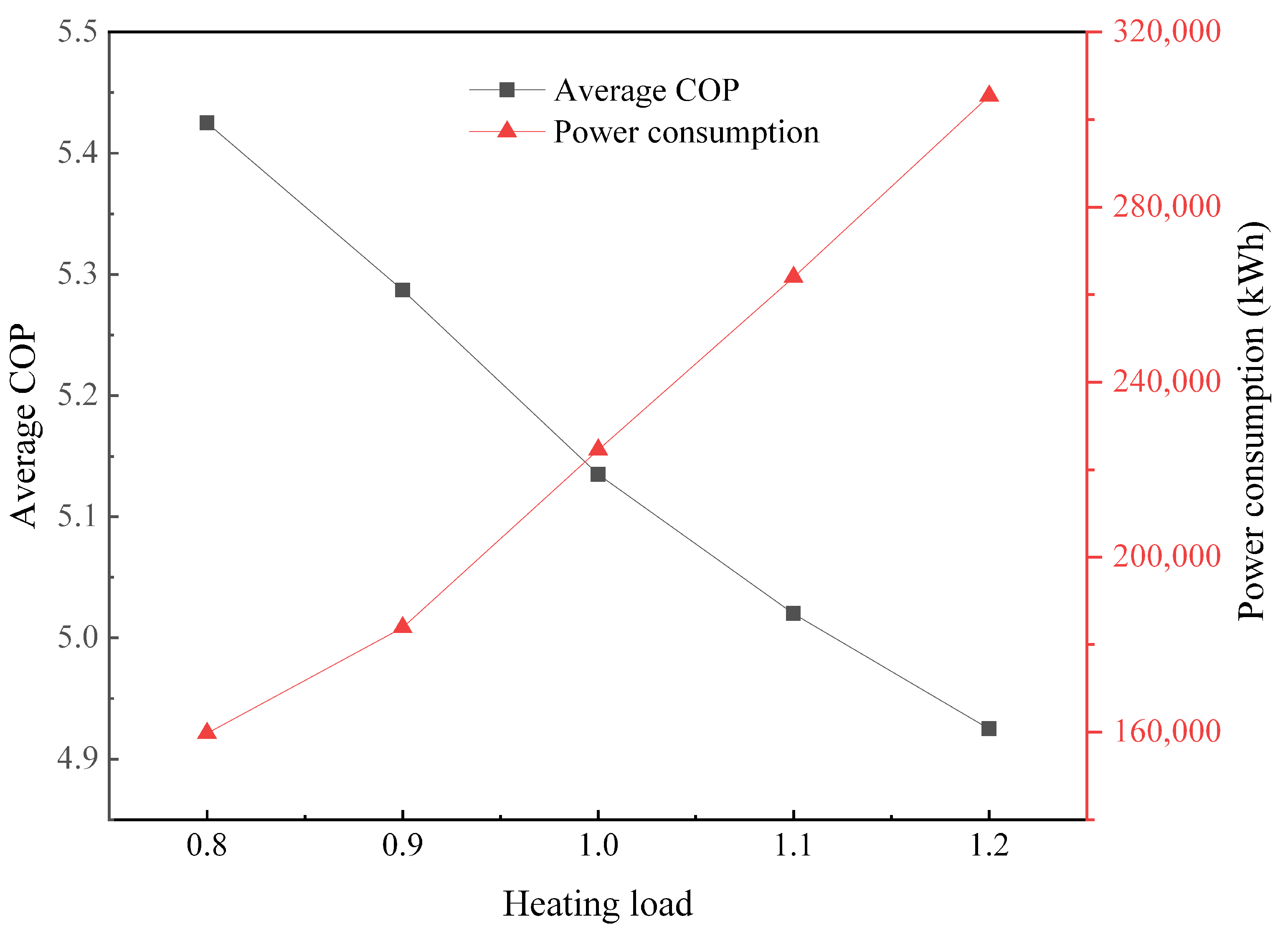
  • When the thermal conductivity of the backfill materials increases, the underground heat transfer will be enhanced, so both the RHS and COP of the system will increase accordingly. As the borehole depth increases, the required flow rate decreases, which significantly reduces the energy consumption of the circulating pump. If the depth increases from 2300 m to 2500 m, the value will decrease from 85,844 kW·h to 56,548 kW·h during the 2112 h operation. An increase in the building thermal load leads to a nearly linear decrease in the COP of the heat pump unit and an increase in total power consumption.

5.2. Outlook

  • The model overlooks groundwater seepage but will be further improved to take its influence into account.
  • It is necessary to obtain the cost information of drilling and equipment, and to conduct economic and environmental benefit analysis in order to apply the research results to actual engineering design processes.
  • The U-type medium-depth GSHP system can be combined with an energy storage system, such as the PCM-based floor [38,39], to achieve more flexible and efficient energy utilization.

Author Contributions

Conceptualization, C.Z., Y.H. and Y.L. (Yongqiang Luo); methodology, C.Z. and Y.L. (Yongqiang Luo); software, Y.L. (Yuce Liu) and R.L.; validation, Y.L. (Yongqiang Luo); formal analysis, C.Z. and X.W.; resources, C.Z. and H.L.; data curation, C.Z.; writing—original draft preparation, C.Z.; writing—review and editing, Y.L. (Yongqiang Luo); visualization, C.Z. and Y.H.; project administration, C.Z. and Y.L. (Yuce Liu); funding acquisition, Y.L. (Yongqiang Luo). All authors have read and agreed to the published version of the manuscript.

Funding

This research was funded by the China Yangtze Power Co., Ltd. grant number Z342302007.

Data Availability Statement

Data will be provided upon reasonable requests.

Conflicts of Interest

The authors declare no conflict of interest.

References

  1. Jolie, E.; Scott, S.; Faulds, J.; Chambefort, I.; Axelsson, G.; Gutiérrez-Negrín, L.C.; Regenspurg, S.; Ziegler, M.; Ayling, B.; Richter, A.; et al. Geological controls on geothermal resources for power generation. Nat. Rev. Earth Environ. 2021, 2, 324–339. [Google Scholar] [CrossRef]
  2. Lund, J.W.; Toth, A.N. Direct utilization of geothermal energy 2020 worldwide review. Geothermics 2021, 90, 101915. [Google Scholar] [CrossRef]
  3. Alhuyi Nazari, M.; Kumar, R.; Mukhtar, A.; Yasir, A.S.H.M.; Ahmadi, M.H.; Al-Bahrani, M. Geothermal energy for preheating applications: A comprehensive review. J. Cent. South Univ. 2023, 30, 3519–3537. [Google Scholar] [CrossRef]
  4. Cui, P.; Yang, W.; Zhang, W.; Zhu, K.; Spitler, J.D.; Yu, M. Advances in ground heat exchangers for space heating and cooling: Review and perspectives. Energy Built Environ. 2024, 5, 255–269. [Google Scholar] [CrossRef]
  5. Zhang, X.; Xu, M.; Liu, L.; Yang, Q.; Ki-Il, S. Heat Storage/Heat Release of Phase-Change Filling Body with Casing Heat Exchanger for Extracting Geothermal Energy. J. Therm. Sci. 2023, 32, 1171–1189. [Google Scholar] [CrossRef]
  6. Qian, M.; Yan, D.; An, J.; Hong, T.; Spitler, J.D. Evaluation of thermal imbalance of ground source heat pump systems in residential buildings in China. Build. Simul. 2020, 13, 585–598. [Google Scholar] [CrossRef]
  7. Yu, M.; Zhang, K.; Cao, X.; Hu, A.; Cui, P.; Fang, Z. Zoning operation of multiple borehole ground heat exchangers to alleviate the ground thermal accumulation caused by unbalanced seasonal loads. Energy Build. 2016, 110, 345–352. [Google Scholar] [CrossRef]
  8. Zhou, W.; Li, R.; Chen, Y.; Zhu, S. Numerical Simulation of Mid-Deep Buried Casing Heat Exchanger and its Heating System Application. J. Therm. Sci. 2023, 32, 1445–1454. [Google Scholar] [CrossRef]
  9. Deng, J.; He, S.; Wei, Q.; Li, J.; Liu, H.; Zhang, Z.; Zhang, H. Field test and optimization of heat pumps and water distribution systems in medium-depth geothermal heat pump systems. Energy Build. 2020, 209, 109724. [Google Scholar] [CrossRef]
  10. Nian, Y.-L.; Cheng, W.-L. Evaluation of geothermal heating from abandoned oil wells. Energy 2018, 142, 592–607. [Google Scholar] [CrossRef]
  11. Jello, J.; Baser, T. Utilization of existing hydrocarbon wells for geothermal system development: A review. Appl. Energy 2023, 348, 121456. [Google Scholar] [CrossRef]
  12. Cheng, W.-L.; Li, T.-T.; Nian, Y.-L.; Wang, C.-L. Studies on geothermal power generation using abandoned oil wells. Energy 2013, 59, 248–254. [Google Scholar] [CrossRef]
  13. Śliwa, T.; Kruszewski, M.; Zare, A.; Assadi, M.; Sapińska-Śliwa, A. Potential application of vacuum insulated tubing for deep borehole heat exchangers. Geothermics 2018, 75, 58–67. [Google Scholar] [CrossRef]
  14. Mehmood, A.; Yao, J.; Fan, D.; Bongole, K.; Liu, J.; Zhang, X. Potential for heat production by retrofitting abandoned gas wells into geothermal wells. PLoS ONE 2019, 14, e0220128. [Google Scholar] [CrossRef]
  15. Mousavi Ajarostaghi, S.S.; Javadi, H.; Mousavi, S.S.; Poncet, S.; Pourfallah, M. Thermal performance of a single U-tube ground heat exchanger: A parametric study. J. Cent. South Univ. 2021, 28, 3580–3598. [Google Scholar] [CrossRef]
  16. Zhang, W.; Li, W.; Sørensen, B.R.; Cui, P.; Man, Y.; Yu, M.; Fang, Z. Comparative analysis of heat transfer performance of coaxial pipe and U-type deep borehole heat exchangers. Geothermics 2021, 96, 102220. [Google Scholar] [CrossRef]
  17. Brown, C.S.; Kolo, I.; Banks, D.; Falcone, G. Comparison of the thermal and hydraulic performance of single U-tube, double U-tube and coaxial medium-to-deep borehole heat exchangers. Geothermics 2024, 117, 102888. [Google Scholar] [CrossRef]
  18. Huang, S.; Li, J.; Zhu, K.; Dong, J.; Jiang, Y. Thermal recovery characteristics of rock and soil around medium and deep U-type borehole heat exchanger. Appl. Therm. Eng. 2023, 224, 120071. [Google Scholar] [CrossRef]
  19. Li, C.; Guan, Y.; Wang, X.; Li, G.; Zhou, C.; Xun, Y. Experimental and numerical studies on heat transfer characteristics of vertical deep-buried U-bend pipe to supply heat in buildings with geothermal energy. Energy 2018, 142, 689–701. [Google Scholar] [CrossRef]
  20. Li, C.; Guan, Y.; Wang, X.; Zhou, C.; Xun, Y.; Gui, L. Experimental and numerical studies on heat transfer characteristics of vertical deep-buried U-bend pipe in intermittent heating mode. Geothermics 2019, 79, 14–25. [Google Scholar] [CrossRef]
  21. Zhang, W.; Wang, J.; Zhang, F.; Lu, W.; Cui, P.; Guan, C.; Yu, M.; Fang, Z. Heat transfer analysis of U-type deep borehole heat exchangers of geothermal energy. Energy Build. 2021, 237, 110794. [Google Scholar] [CrossRef]
  22. Yu, M.; Wei, L.; Fangfang, Z.; Wenke, Z.; Ping, C.; Zhaohong, F. A novel model and heat extraction capacity of mid-deep buried U-bend pipe ground heat exchangers. Energy Build. 2021, 235, 110723. [Google Scholar] [CrossRef]
  23. Chen, C.; Cai, W.; Naumov, D.; Tu, K.; Zhou, H.; Zhang, Y.; Kolditz, O.; Shao, H. Numerical investigation on the capacity and efficiency of a deep enhanced U-tube borehole heat exchanger system for building heating. Renew. Energy 2021, 169, 557–572. [Google Scholar] [CrossRef]
  24. Ramey, H.J. Wellbore Heat Transmission. J. Pet. Technol. 1962, 14, 427–435. [Google Scholar] [CrossRef]
  25. Bao, L.; Wang, X.; Jin, P.; Cui, J.; Zhu, Y.; Wang, Y. An analytical heat transfer model for the mid-deep U-shaped borehole heat exchanger considering groundwater seepage. J. Build. Eng. 2023, 64, 105612. [Google Scholar] [CrossRef]
  26. Shen, J.; Zhou, C.; Luo, Y.; Tian, Z.; Zhang, S.; Fan, J.; Ling, Z. Comprehensive thermal performance analysis and optimization study on U-type deep borehole ground source heat pump systems based on a new analytical model. Energy 2023, 274, 127367. [Google Scholar] [CrossRef]
  27. Wang, C.; Sun, W.; Fu, Q.; Lu, Y.; Zhang, P. Semi-analytical and numerical modeling of U-bend deep borehole heat exchanger. Renew. Energy 2024, 222, 119959. [Google Scholar] [CrossRef]
  28. Wang, X.; Bao, L.; Jin, P.; Zhu, Y. Analytical model of heat transfer of U-shaped borehole heat exchanger under convolution theory and its optimal heat extraction analysis. Int. J. Therm. Sci. 2023, 193, 108496. [Google Scholar] [CrossRef]
  29. Jiang, J.; Wang, F.; Yang, X.; Zhang, Y.; Deng, J.; Wei, Q.; Cai, W.; Chen, C. Evaluation of the long-term performance of the deep U-type borehole heat exchanger on different geological parameters using the Taguchi method. J. Build. Eng. 2022, 59, 105122. [Google Scholar] [CrossRef]
  30. Huang, S.; Li, J.; Zhu, K.; Dong, J.; Jiang, Y. Influencing factors analysis for the long-term thermal performance of medium and deep U-type borehole heat exchanger system. J. Build. Eng. 2023, 68, 106152. [Google Scholar] [CrossRef]
  31. Huang, S.; Li, J.; Zhu, K.; Dong, J.; Jiang, Y. Multifactor optimization of medium and deep U-type borehole heat exchanger design using Taguchi method. Geothermics 2023, 109, 102644. [Google Scholar] [CrossRef]
  32. Wang, G.; Ma, H.; Liu, S.; Yang, D.; Xu, X.; Fu, M.; Jia, H. Thermal power extraction from a deep, closed-loop, multi-level, multi-branch, U-shaped borehole heat exchanger geothermal system. Renew. Energy 2022, 198, 894–906. [Google Scholar] [CrossRef]
  33. Luo, Y.; Guo, H.; Meggers, F.; Zhang, L. Deep coaxial borehole heat exchanger: Analytical modeling and thermal analysis. Energy 2019, 185, 1298–1313. [Google Scholar] [CrossRef]
  34. Li, C.; Guan, Y.; Wang, X. Study on reasonable selection of insulation depth of the outlet section of vertical deep-buried U-bend tube heat exchanger. Energy Build. 2018, 167, 231–239. [Google Scholar] [CrossRef]
  35. Holmberg, H.; Acuña, J.; Næss, E.; Sønju, O.K. Thermal evaluation of coaxial deep borehole heat exchangers. Renew. Energy 2016, 97, 65–76. [Google Scholar] [CrossRef]
  36. Casasso, A.; Sethi, R. Efficiency of closed loop geothermal heat pumps: A sensitivity analysis. Renew. Energy 2014, 62, 737–746. [Google Scholar] [CrossRef]
  37. Hein, P.; Kolditz, O.; Görke, U.-J.; Bucher, A.; Shao, H. A numerical study on the sustainability and efficiency of borehole heat exchanger coupled ground source heat pump systems. Appl. Therm. Eng. 2016, 100, 421–433. [Google Scholar] [CrossRef]
  38. Hariti, Y.; Hader, A.; Faraji, H.; Boughaleb, Y. Scaling Law of Permeability and Porosity for Fluid Transport Phenomena in Porous PCM Media. J. Appl. Comput. Mech. 2021, 7, 84–92. [Google Scholar] [CrossRef]
  39. Babaharra, O.; Choukairy, K.; Faraji, H.; Hamdaoui, S. Improved heating floor thermal performance by adding PCM microcapsules enhanced by single and hybrid nanoparticles. Heat Transfer 2023, 52, 3817–3838. [Google Scholar] [CrossRef]
Figure 1. Schematic of deep U-shaped buried pipe heat exchanger.
Energies 17 03184 g001
Figure 2. Comparison of simulated outlet temperature with experimental data.
Energies 17 03184 g002
Figure 3. The calculation process of variable-flow operation.
Energies 17 03184 g003
Figure 4. The building thermal load.
Energies 17 03184 g004
Figure 5. The variation curves of water flow rate and RHS over time.
Energies 17 03184 g005
Figure 6. The fluctuation curves of inlet and outlet temperatures, along with the COP of the heat pump unit over time.
Energies 17 03184 g006
Figure 7. The frequency distribution of RHS under different thermal conductivity coefficients of backfill materials.
Energies 17 03184 g007
Figure 8. The variation curves of COP over time under varying thermal conductivity coefficients of backfill materials.
Energies 17 03184 g008
Figure 9. The frequency distribution of RHS under different pipe lengths.
Energies 17 03184 g009
Figure 10. The variation curves of COP over time under varying pipe lengths.
Energies 17 03184 g010
Figure 11. The frequency distribution of RHS under different percentage loads.
Energies 17 03184 g011
Figure 12. The variation in COP of the heat pump unit and total power consumption with building thermal load.
Energies 17 03184 g012
Table 1. Basic parameters.
Conditions
Drilling diameter db215.9 mmDensity of circulating water ρf995.7 kg/m3
Drilling depth H2520 mThermal conductivity of circulating water λf0.618 W/(m·K)
Horizontal drilling length L210 mSpecific heat capacity of circulating water cf4174 J/(kg·°C)
Insulation section drilling diameter dbins 444.5 mmInsulation material volume heat capacity Cins7.74 × 104 J/Km3
Insulation section depth Hins350 mInsulation material thermal conductivity λins0.022 W/(m·K)
Insulation layer thickness40 mmHeat capacity of backfill material Cg2.5 × 106 J/Km3
Outer diameter of descent pipe dor139.7 mmThermal conductivity of backfill material λg1.5 W/(m·K)
Wall thickness of descent pipe9.17 mmSpatial step Δx/Δz35 m
Outer diameter of ascent pipe doc177.8 mmTime step Δτ3600 s
Wall thickness of ascent pipe8.05 mm -
Disclaimer/Publisher’s Note: The statements, opinions and data contained in all publications are solely those of the individual author(s) and contributor(s) and not of MDPI and/or the editor(s). MDPI and/or the editor(s) disclaim responsibility for any injury to people or property resulting from any ideas, methods, instructions or products referred to in the content.

