Abstract
This study investigates the crucial role of Carbon Capture and Storage (CCS) technology in mitigating CO2 emissions from Poland’s power systems, which is essential not only for meeting climate targets but also for maintaining energy security in the country. Acknowledging natural gas as a transitional fuel, the focus is on evaluating the decarbonization potential of the natural gas combined cycle (NGCC) power plant. The NGCC with and without an amine-based carbon capture unit was modeled using IPSEpro (SimTech, version 7.0). It was found that the annual CO2 emission from 435.68 MWe (net) NGCC can be reduced from 1,365,501 tons (357.8 kgCO2/MWh) to 136,556 tons (42.9 kgCO2/MWh). On the other hand, the CCS reduced the net electric power of the NGCC from 435.68 MW to 363.47 MW and the net energy efficiency from 55.60% to 46.39%. Nonetheless, these results demonstrate the potential of using the amine-based CO2 capture technology in NGCC systems. This is especially important in the context of the decarbonization of the Polish power system.
1. Introduction
The urgency behind transitioning to a low-carbon energy system arises from the alarming rate at which societies are depleting their carbon budget. As shown in Figure 1, 2560 Gt of CO2 was emitted between 1750 and 2019, and the remaining carbon budget represents the allowable amount of CO2 that can still be emitted to limit warming below specific temperature thresholds (1.5 °C or 2.0 °C) [1].
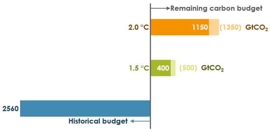
Figure 1.
Various types of carbon budgets (own elaboration based on [1]).
The annual global emissions of CO2, as of 2022, stand at approximately 36.5 billion tons, resulting in an average daily emission of 100 million tons (0.1 billion tons) [2]. Consequently, if such a high emission rate persists, the 1.5 °C and 2.0 °C thresholds will be reached within 10 to 13 years and 31 to 36 years, respectively, with 67% and 50% probability. Hence, each emitted ton of CO2 counts, as every reduction contributes to the mitigation of climate change.
Therefore, developing a comprehensive transition plan for the entire coal value chain is crucial to align with the rapid energy transition required by 2030, promoting carbon neutrality and ensuring a fair transition. This plan should prioritize the integration of carbon capture, utilization, and storage (CCUS) technologies, recognizing that fossil fuels will continue to play a role in power generation in Poland [3]. According to the Energy Policy of Poland until 2040 (PEP2040) [3], the share of coal in electricity production will be reduced to 56% by 2030 and further decrease thereafter. As a result, the share of natural gas will increase, and to address the remaining CO2 emissions from fossil fuels, PEP2040 assumes the development of CCS. Although conversion to natural gas and the implementation of CCS can boost CO2 emission reductions, several dilemmas arise. Natural gas deposits in Poland are not as large as coal reservoirs, which will lead to a dependency on natural gas imports. Furthermore, the large-scale deployment of CCS technology is still emerging and carries some concerns regarding technology readiness level, economic feasibility, and long-term CO2 storage security. Nonetheless, this study focuses on deploying CCUS as a transitional solution in line with the statements from the International Energy Agency (IEA) and the Intergovernmental Panel on Climate Change (IPCC), emphasizing the need to capture between 15% and 20% of global CO2 emissions to limit global warming below 2 °C [4,5]. Translating this into action, apart from electrification, renewables, or hydrogen implementation, CCUS will require a rapid scale-up to about 5 and 7 gigatons (Gt) per year [4]. Applied to Poland, the achievement of this target requires injecting between 21 and 28 million tons of CO2 from commercial power plants alone, and 60 to 80 million tons of CO2 from all sectors, into suitable underground storage sites each year by the end of the century [6].
Coal-fired power plants play a dominant role in electricity production in Poland. In 2022, the country produced 178.8 TWh, with fossil fuels accounting for approximately 77% of the total production share [6]. As a result, the electricity, heat production, and industry sectors collectively contributed to 53.4% of the total emissions, amounting to 215.7 Mt of CO2eq [6]. One possible solution to the CO2 emissions problem is carbon capture and storage (CCS) technology.
CCS is a focused approach for a climate change mitigation strategy. The post-combustion CCS process begins with the capture of CO2 emissions from major industrial point sources, including operations such as cement and chemical production or coal and biomass power plants. There are a variety of post-combustion capture methods which can be grouped by the physicochemical processes used to separate the gasses [7]:
- Solvent-based, where an absorption liquid is used;
- Sorbent-based, where adsorption solid particles are used;
- Cryogenic, where different gas condensation temperatures are used;
- Membranes, where solid-state chemical barriers are used.
In the capture process, CO2 is effectively removed from flue gasses before they are released into the atmosphere. Once captured, the CO2 is then purified and compressed, usually transforming it into a liquid state to be injected and permanently stored in suitable underground formations. Alternatively, if CO2 storage is not pursued, there is the option of utilization. This involves CO2 conversion into biofuels or fertilizers [8], as well as its employment in greenhouse applications for agriculture [9]. By reusing captured CO2 for various industrial purposes or transforming it into valuable products, the circular carbon economy is fostered.
Considering the storage of CO2, underground geological formations, including depleted oil and gas fields, coal beds, and saline aquifers, typically serve as secure storage sites for captured CO2 [10]. Transportation can be accomplished through pipelines, ships, or tankers, with ship transport increasingly recognized as a viable option for many regions worldwide, drawing from the knowledge gained from transporting Liquified Natural Gas (LNG) [11]. Indeed, the comprehensive process of CCUS carries the potential to significantly mitigate global emissions and promote a more sustainable future.
Regarding the post-combustion capture processes, absorption-based technologies are considered to be the most mature and commercially available [12]. Typically, the absorption-based carbon capture process is as follows. Flue gas enters the absorption column, where a counter-current flowing lean sorbent solution, e.g., monoethanolamine (MEA) [13], absorbs CO2 from the flue gas. The rich (i.e., CO2-loaded) sorbent solution flows to the desorption column, while the CO2-free flue gas is emitted to the atmosphere. The rich sorbent solution is heated in the desorption column, which results in the release of CO2. Pure CO2 then goes into the compression and purification unit, while the lean sorbent solution returns to the absorption column [14].
Numerous studies regarding the improvement of absorption-based CO2 capture technology have been conducted. This research concerns improvements in various aspects, e.g., improving sorbent properties [15,16], optimizing the operating parameters of the CO2 capture unit [17,18,19], changing the configuration of the CCS unit [20], or using a multi-stage membrane module for selective exhaust gas recirculation (SEGR) and the combination of turbine exhaust gas recirculation with SEGR [21]. There have also been attempts to use renewable energy sources (e.g., solar energy) to power CCS installations [22]. Additionally, Omehia et al. [23] investigated the performance of CCS operating under various fuel compositions, and it was found that increasing the CO2 concentration in flue gas improves the performance of the CCS unit.
Although research on improving the CO2 capture process is of significant importance, studying the impact of CO2 capture technology on the entire power plant is also crucial. As the CCS technology requires heat for sorbent regeneration and electricity for powering pumps, etc., the integration of the CCS technology with power plants affects the performance of the latter. The CCS usually leads to a reduction in the net electric power and efficiency of the power plant [24]. However, it allows for a decrease in the CO2 emission rate per kilowatt-hour generated [25]. Going further, the integration of CCS with a natural gas combined cycle (NGCC) can even lead to negative CO2 emissions when direct air capture is additionally utilized [26]. Nonetheless, a simple CCS unit without any other improvements negatively affects the performance of the power plant. Several papers regarding the effect of CCS on the performance of power plants can be found in the available literature. For example, Mohammed et al. [27] used the life cycle assessment methodology to examine the CCS integrated with the natural gas combined cycle (NGCC) power plant in Iraq. Shao et al. [28] investigated the NGCC coupled with amine-based CCS in China and reported that the reduction in CO2 emissions by 100 g per each generated kWh increased the levelized cost of electricity by up to 13.5%.
This work emphasizes the need for sustainable solutions that balance environmental concerns with energy security while closing the loop on CO2 emissions. The research aims to assess the impact of CCS technology on the performance of a Natural Gas Combined Cycle (NGCC) power plant. In this study, the NGCC power plant was integrated with an amine-based CO2 capture system and investigated by computer simulations employing IPSEpro (SimTech GmbH, version 7.0). The key operating parameters of the NGCC with and without CCS were indicated. The key operating parameters included the net electric power and net energy efficiency of the NGCC, CO2 captured and emitted per year, and the electrical power required for flue gas and CO2 compression. Also, the annual emission of CO2 and the costs associated with it were determined. All of the abovementioned calculations were conducted for various shares of flue gasses directed to the carbon capture unit. This research contributes to the advancement of CCS technologies, supporting the transition into sustainable and low-carbon energy systems in Poland.
2. Materials and Methods
This work develops a comprehensive numerical model of the NGCC power plant integrated with amine-based CO2 capture technology and a CO2 compression system, as shown in Figure 2. Firstly, the model of the NGCC power plant is modeled in the IPSEpro (SimTech, version 7.0). Technical data for modeling the installation were based on documents related to commissioning [29], data from the GateCycle software (version 5.51), and data from the NETL [30,31] study. Then, the post-combustion CO2 capture method (amine-based) and CO2 compression system were integrated with the NGCC, and their performance was investigated using IPSEpro. The analysis was conducted in such a way as to investigate the performance of the system depending on the share of flue gasses directed to the carbon capture unit.

Figure 2.
The methodology of research—systems analyzed in this paper.
The analyzed system is presented in Figure 3. The system consists of the NGCC power plant (gross electric power of 474 MW, steam extraction of 120 t/h for technological purposes) [29] and an amine-based CCS unit. In the power plant, the air is compressed in the compressor and goes to the combustion chamber. In the combustion chamber, the fuel (natural gas) is burned and the flue gasses generated are then expanded in the gas turbine. The flue gas leaving the gas turbine is then directed to the heat recovery steam generator (HRSG). The steam generated in the HRSG is expanded in the steam turbine, cooled in the condenser, and pumped (as per the Rankine cycle). The flue gas leaving the HRSG is compressed to 1.2 bar and directed to the amine-based carbon capture unit. The carbon capture unit is composed of the absorber, desorber, and heat exchanger. The CO2 is absorbed by the amine solution in the absorber. Then, the CO2-rich amine solution passes through the heat exchanger and flows to the desorber, where the CO2 is released from the amine solution as heat is applied in the form of steam from the steam turbine. The released CO2 is then compressed and transported to the storage site, while the regenerated amine solution goes back to the absorber.
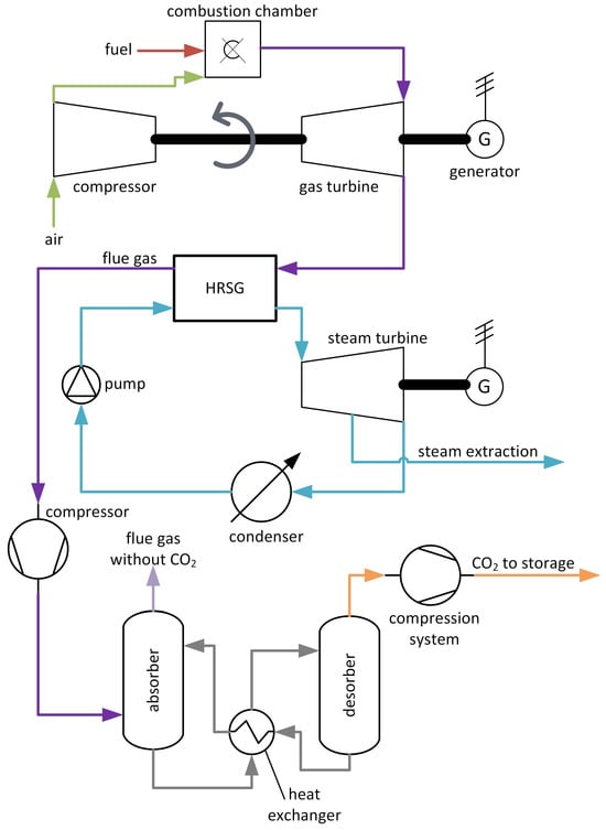
Figure 3.
Diagram of the NGCC with CCS.
By adopting co-generation principles, the power plant not only generates electricity but also harnesses useful heat, maximizing energy utilization and contributing to reduced emissions. The NGCC power plant is a power generation facility that utilizes both gas turbines and steam turbines to produce electricity. The plant operates in two main cycles, the gas turbine cycle and the steam turbine cycle, which are combined to maximize efficiency and power generation. The combination of the gas turbine and steam turbine cycles significantly improves the overall efficiency of the power plant compared to a standalone gas turbine plant.
The model of the investigated system (NCGG with CCS) was implemented into IPSEpro software. The software allows the entire system to be built from the components (e.g., gas turbine, steam turbines, pumps, heat exchangers, etc.) available in the IPSEpro library. Additional data and assumptions were derived from the GateCycle software and the NETL document [30]. Each component is described mathematically with appropriate algebraic mass and energy conservation equations. Then, after specifying the input data (Table 1), the equations are solved and the following parameters are obtained: gross electric power of gas and steam turbines, the power plant’s own electricity consumption, electric power to compress flue gasses to 1.2 bar (before carbon capture unit), electric power for CO2 compression, net electric power of the power plant, net power plant efficiency, captured and emitted CO2, and mass flow rate of steam used for sorbent regeneration. These parameters are assessed both in the existing setup and in the simulated scenario with integrated CCS. The modeling is focused on the impact of CCS integration on the power plant’s operational parameters in the function of the share of flue gas, in the range of 5% to 100%, directed to the CCS unit.

Table 1.
Input data to the IPSEpro simulations.
3. Results and Discussion
3.1. Model Validation
Table 2 presents a summary of the key operational parameters of the NGCC power plant operating at a nominal load of 100% with the production of process steam at 120 t/h, without CCS. The table comprises data from the power plant and those calculated using IPSEpro. The data provided by the power plant are compared to the results of simulations. As can be seen, the results of the simulations agree fairly well with the data from the power plant. Thus, the developed model is valid and can be used in further simulations.
Table 2.
Operating parameters of the investigated NGCC and results simulations.
3.2. Case Scenario for CO2 Capture
The total modeled flue gas stream remains constant at 671.03 kg/s, of which 43.30 kg/s is CO2, throughout the operation of the NGCC power plant. If the total flue gas (100%) is directed to the carbon capture unit, the process yields a pure CO2 stream of 38.97 kg/s out of the 671.03 kg/s of flue gas with an assumption of 90% CO2 capture efficiency. Decreasing the share of flue gas directed to the carbon capture unit from 100% to 5% results in a linear decrease in the capture CO2, as shown in Figure 4. Thus, the flue gas flow rate through the CO2 capture unit is 33.55 kg/s at 5% operation, while the remaining exhaust stream, equal to 637.48 kg/s, of which 41.35 kg/s is CO2, is emitted into the atmosphere. Finally, 1.95 kg/s of CO2 is captured and compressed in the case of a 5% share of the flue gas directed to the carbon capture unit.
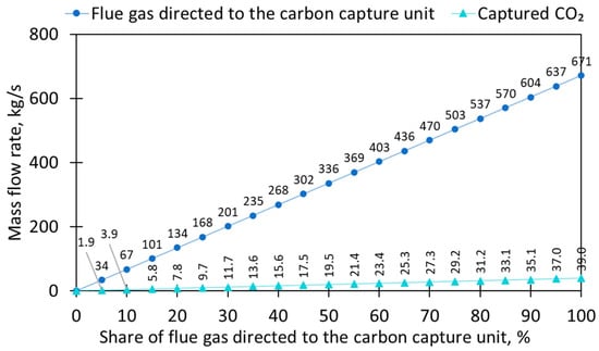
Figure 4.
Mass flow rate of the flue gas directed to the carbon capture unit and captured CO2.
The cumulative annual CO2 emissions from the NGCC power plant (Figure 5) are 1,365,501 tons if no carbon capture technology is applied. However, this translates to an annual potential of CO2 emission reduction of 1,228,945 tons if the amine-based CCS technology with 90% CO2 capture efficiency, examined in this project, is to be retrofitted at the NGCC power plant and if all flue gas is directed to the CCS unit. The adjustment in the capture rate is made to highlight the impact of CCS on the decarbonization of power systems, even at lower capture rates. At a 5% share of flue gas directed to the carbon capture unit, about 61,447 tons of CO2 can be captured annually. The importance of this capture becomes more evident when the rate reaches 40%, which translates into an annual capture of approximately 500,000 tons of CO2. However, the true impact takes place at an 80% capture rate, where a substantial reduction of nearly 1 million tons of CO2 per year is achieved. This reduction represents a significant contribution to mitigating climate change, particularly within the Polish context, marking an important milestone in carbon abatement within the power sector.
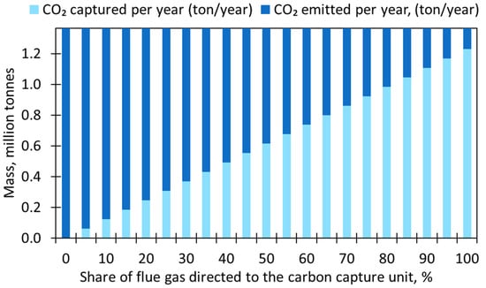
Figure 5.
CO2 emitted per year and CO2 captured per year.
Although the amine-based carbon capture technology has great potential to reduce CO2 emissions from the power sector, it also impacts the performance of the investigated NGCC power plant. Heat, in the form of steam, is required in the amine-based CO2 capture unit for sorbent regeneration. Thus, part of the steam generated in the HRSG must be extracted and diverted for sorbent regeneration purposes in the CO2 capture unit. Also, flue gas leaving the gas turbine and then HRSG has a pressure of 1 bar and must be compressed to 1.2 bar before entering the CO2 capture unit due to pressure losses in the absorber column. Secondly, pure CO2 leaving the CO2 capture unit is compressed to 100 bar (and cooled to a temperature of approximately 30 °C) to achieve a supercritical state. As a result, the use of CCS technology is linked to heat demand and electrical power demands.
Figure 6 presents the mass flow rate of steam in the CO2 capture unit. The steam mass flow rate increases linearly from 2.43 kg/s (for a 5% share of flue gas) to 47.61 kg/s (for a 100% share of flue gas). This steam extraction affects electric power generation in the steam turbine. The electric power generated via the steam turbine is 135.36 MW when CCS is not used and it decreases to 92.07 MW when CCS is used and 100% of flue gas is directed to the CO2 capture unit. Meanwhile, the electric power generated via the gas turbine remains constant at 303.14 MW. As mentioned in the previous paragraph, there is also a CCS-related electric power demand for flue gas compression and pure CO2 compression. This CCS-electric-power-demand reaches a maximum value of 28.91 MW for a 100% share of flue gas.
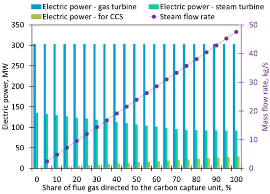
Figure 6.
Electric power supply and demand, and mass flow rate of steam directed to the carbon capture unit.
Even though integrating the CO2 capture unit into the NGCC power plant decreases its net electric power generation, it reduces the CO2 emissions related to the generated electricity, as is presented in Figure 7. The CO2 emission rate is 357.8 kgCO2/MWh when no CCS is used. However, it drops significantly to a minimum value of 42.9 kgCO2/MWh after applying the carbon capture technology. This proves that CO2 capture technology reduces the emissions of CO2 more than it reduces electricity generation.
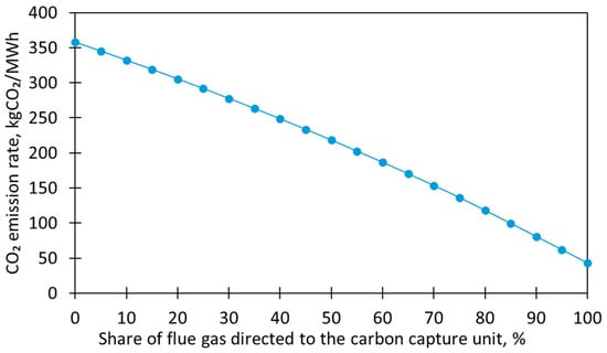
Figure 7.
CO2 emission rate.
The primary challenges associated with proposing CCS as an alternative solution within low-carbon power systems are intricately linked to the energy-intensive nature of CO2 capture. This aspect is particularly evident in the context of the NGCC power plant, as depicted in Figure 8. It shows the power requirements for both exhaust gas compression and subsequent CO2 compression as functions of different CO2 recovery percentages. As can be seen, the electric power demand for flue gas compression before the CO2 capture unit stands for approximately 59% of the total CCS-related electric power consumption. This ratio remains constant for the entire range of the share of flue gas directed to the CO2 capture unit. The high electrical energy demand for flue gas compression is due to a high mass flow rate of flue gas, i.e., a maximum of 671 kg/s, while the maximum pure CO2 mass flow rate is 39 kg/s. Thus, because of a higher mass flow rate, the compression of flue gas is more energy-consuming than the compression of pure CO2. Total electric power demand in the CCS system at the lower end, with a 5% CO2 recovery rate, is relatively moderate at 1.445 MW. However, as the CO2 recovery percentage approaches 100%, the power requirement increases significantly, reaching a peak of 28.9 MW.
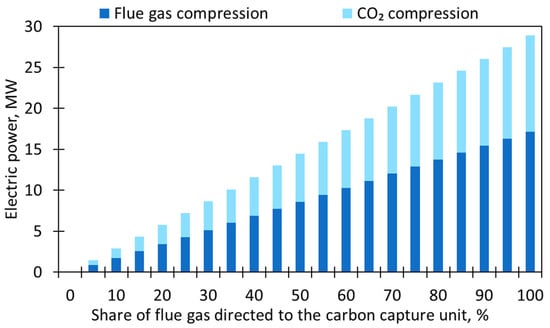
Figure 8.
Electric power demand for flue gas compression and CO2 compression.
Integrating the CCS technology into the NGCC power plant impacts the net energy efficiency of the NGCC η (%), with reference to lower heating value (LHV, kJ/kg), and defined as
where PGT (kW) and PST (kW) are electric power generated via gas and steam turbine generators, respectively, Pown (kW) stands for the needs of the NGCC power plant (electrical energy required for mechanical devices such as pumps), PCCS (kW) is the power demand for CCS purposes, and is the mass flow rate of fuel (kg/s). Both the steam extraction and the electricity demand for flue gas and CO2 compression affect the net energy efficiency of the power plant. The net efficiency stands at 55.60% when operating without CCS. However, after introducing the CCS, this efficiency metric undergoes notable changes, as depicted in Figure 9. Initially, at a 5% flue gas recovery rate, the net efficiency is measured at 55.05%, which represents a decrease of 0.55 percentage points compared to the efficiency when no CCS is in place. The rate at which the efficiency goes down stays steady at an average of 0.55 percentage points with every 5% step of the capture rate from 5% to 75%. Remarkably, as the CO2 recovery rate is increased to 80%, there is a change in this trend. The average values decrease from 0.54 percentage points to 0.21 percentage points per 5% of capture share. Such a change is directly attributable to the extraction of steam for the regeneration of amines in the capture unit. When 5–75% of the flue gasses are directed to the capture unit, there are 2 steam extraction points; for process purposes at 120 t/h and for the regeneration of amines, which influences the described decrease in efficiency of the power plant unit. However, when 80% or more of the flue gasses are directed to the CO2 capture unit, the amount of steam produced for technological purposes has to be reduced due to the increasing heat demand in the carbon capture unit due to the technological limitations of the plant. Therefore, when 80% of the flue gasses are directed to the capture unit, the amount of steam that can be produced for process purposes is 112 t/h, and each 5% increase in the flue gas stream is associated with a reduction in process steam of 8 t/h. In turn, a reduction in process steam production is associated with a smaller decrease in the net efficiency of the power plant unit, as observed in Figure 9. Then, as the CO2 capture rate reaches 100%, the final efficiency is 46.39%. This signifies an overall decrease of 9.09 percentage points in efficiency when CCS is implemented in the NGCC power plant.
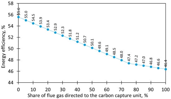
Figure 9.
Net energy efficiency.
The summary of the impact on electricity generation when integrating CCS is presented in Table 3 and Figure 10. As the flue gas recovery rate increases, the electric power for flue gas and CO2 compression increases, resulting in a drop in the net electric power of the NGCC power plant. For instance, at a 50% recovery rate, CCS requires 14.45 MW of power, causing a 9.8% decrease in net power, equivalent to 392.87 MW, compared to the starting value. In this case, the CCS electric power requirements represent 3.7% of the total net power produced by the NGCC power plant. To put this in perspective, against the initial simulated total net electrical output of 435.68 MW, the achievement of 100% CO2 recovery from the flue gas results in a net output of 363.47 MW with 28.91 MW power demand by the CCS. The power required by the CCS accounts for 8.0% of the net NGCC power plant’s power production.
Table 3.
Key performance parameter indicators.
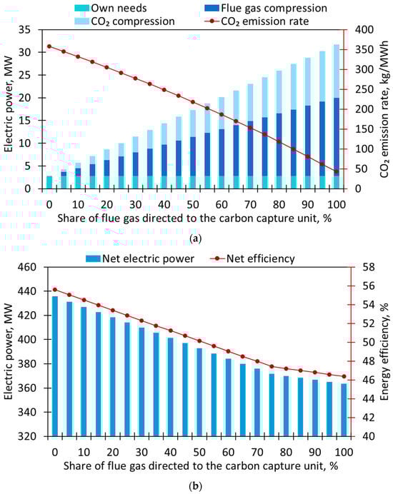
Figure 10.
Summary of the results: (a) electric power for own needs, flue gas compression and CO2 compression, and CO2 emission rate; (b) net electric power and net energy efficiency of the investigated NGCC.
3.3. Economic Scenario
In this paper, the economic implications of reducing CO2 emissions within the Polish power sector were examined. To assess this impact, the authors relied on the current carbon tax rate in Poland, which has consistently remained one of the lowest in Europe at EUR 0.07 per ton of CO2 since 1990, as reported by the World Bank dataset comparison [33]. Additionally, carbon tax rates from other European countries were also considered. Notably, Norway, one of the most committed countries to achieving Net-Zero emissions in the EU, was found to have a carbon tax rate of EUR 84.76 per ton of CO2. Additionally, Portugal, known for its greener energy matrix, was also included, with a carbon tax rate of EUR 24 per ton of CO2. Also, the EU ETS was referenced with a rate of EUR 89 per ton of CO2. Furthermore, it was factored into the average carbon tax rate in Europe, which stood at EUR 42.77 per ton of CO2 for the purposes of this analysis. This consideration is based on the expectation that Poland’s carbon tax may eventually align with the rates observed in other EU member countries, which could significantly impact the economics of emission reduction in the Polish power sector.
Figure 11 provides a visual representation of the economic impact due to CO2 emissions of a 435 MW NGCC power plant in Poland, when compared to its potential performance in different countries or under varying carbon pricing scenarios. The figure clearly illustrates that, given the current carbon tax rate in Poland, the implementation of CCS may not be economically sustainable. The cost associated with emitting 1,365,501 tons of CO2 annually, as computed using IPSEpro, amounts to only EUR 95,585.10 when subject to a tax rate of EUR 0.07 per ton of CO2. In contrast, this cost increases significantly to EUR 32,772,033.90 if the same NGCC plant were situated in Portugal, or EUR 58,402,495.42 when subjected to the EU average carbon tax rate. Furthermore, this cost escalates sharply when compared to the carbon tax rate in Norway, reaching EUR 115,739,899.74, or EUR 121,529,625.73 under the EU ETS.
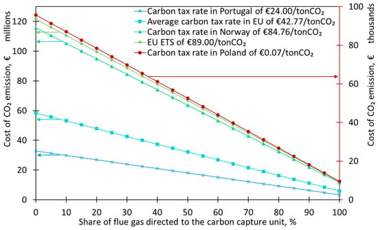
Figure 11.
Cost of CO2 emissions in Poland compared to other European countries.
On the other hand, the use of the discussed CCS technology in the existing NGCC power plant can reduce the costs associated with CO2 emissions to EUR 9558.93, EUR 3,277,348.44, EUR 5,840,508.03, EUR 11,574,502.24, and EUR 12,153,500.47 in the case of carbon tax rates in Poland, Portugal, the EU, Norway, and the EU ETS, respectively. It gives a percentage reduction of 90% as compared to the CO2 emission costs without CCS.
3.4. Comparison to the Literature
The results obtained in this study were compared to the results published in the available literature, which are shown in Table 4. In all compared works, the NGCC power plant without CCS was the base case. Then, the amine-based CCS technology was integrated into the base NGCC, and the crucial operating parameters, i.e., net electric power, net energy efficiency, and mass of the emitted CO2, were compared.
As can be seen, in almost all references and this work, the implementation of CCS lowered the annual CO2 emission by 90%. Only in the case of Oh et al. [34] was the reduction 95%. It is also obvious that the net electric power and net energy efficiency decreased after CCS utilization in all cases. The greatest drop in net electric power was reported in this paper and by Oh et al. [34] (by 16.6%), while the slightest decline, by 10.5%, was reported by Carapellucci et al. [35]. The same results were reported regarding the net energy efficiency—the lowest drop was by 9.6% (5.4 percentage points), while the greatest drop was by 16.7% (8.4 percentage points). Generally, the results obtained in this paper are in agreement with the results reported in the available literature. Slight differences between the individual works may result from different operational parameters of the NGCC systems themselves (e.g., isentropic efficiency of gas turbines), and CCS (e.g., temperature and pressure in the absorption column), and the CO2 compression system (e.g., CO2 temperature and pressure after compression).
Table 4.
Results comparison between this work and other works from the available literature.
Table 4.
Results comparison between this work and other works from the available literature.
| Reference | Without CCS | With CCS | ||||
|---|---|---|---|---|---|---|
| Pnet, MW | η, % | MCO2, tons/year | Pnet, MW | η, % | MCO2, tons/year | |
| Strojny et al. [36] | 735.5 | 57.7 | 1,998,435 | 628.4 | 49.3 | 199,843 |
| Oh et al. [34] | 580.4 | 52.6 | 1,844,190 | 484.2 | 43.8 | 90 044 |
| Ystad et al. [37] | 444.0 | 58.26 | n.a. | n.a. | 51.07–52.00 * | n.a. |
| Sipöcz et al. [38] | 442.0 | 58.29 | 1,359,289 | 377.8 | 49.81 | 130,874 |
| Carapellucci et al. [35]—NGCC 1 | 384.0 | 56.1 | 1,240,248 | 343.5 | 50.7 | 122,770 |
| Carapellucci et al. [35]—NGCC 2 | 153.9 | 50.6 | 552,747 | 137.0 | 45.6 | 54,485 |
| Carapellucci et al. [35]—NGCC 3 | 50.0 | 48.5 | 187,683 | 42.8 | 41.9 | 18,484 |
| Lindqvist et al. [39] | 416.4 | 58.13 | 1,294,921 | 354.3 | 51.41 | 124,147 |
| This work | 435.68 | 55.60 | 1,365,501 | 363.47 | 46.39 | 136,556 |
MCO2—mass of emitted CO2, tons/year; * depending on the case.
Although the results obtained in this study are comparable with the results from the available literature, it must be remembered that some simplifications were assumed. For example, this work did not include auxiliary systems, e.g., a dehydration unit for water removal from CO2. Usually, water removal from CO2 is obligatory due to stringent requirements regarding CO2 purity for pipeline transport. Additionally, implementing the amine-based CCS technology into an existing power plant is related to the necessity of retrofitting the power plant, which is expensive and technically difficult.
Considering all simplifications assumed in this study and bearing in mind that CCS is becoming increasingly implemented in many facilities, further research on CCS is essential. Thus, as part of further research, it is suggested that an analysis is carried out that would also take into account the auxiliary installations mentioned in the paragraph above. Possible directions for further research on CCS also include research on the use of amine technology in other types of power plants and combined heat and power plants, as well as in other industries, e.g., in the lime industry. It would also be worth analyzing a comparison of other CCS technologies, e.g., cryogenic or calcium looping technology for use in various facilities.
4. Conclusions
In this paper, the potential of CO2 emission reduction from the NGCC power plant using amine-based carbon capture technology was assessed. The key conclusions from the analysis can be drawn as follows.
- The annual CO2 emissions from the investigated 435 MW NGCC power plant are 1,365,501 tons when no CCS is used and can be reduced to 136,556 tons if the entire flue gas is directed to the CO2 capture unit with a CO2 capture efficiency of 90%.
- Using CCS technology impacts the NGCC power plant’s operational parameters, particularly in terms of energy efficiency, energy consumption, and power generation.
- CCS technology comes with increased energy demands, both electric and thermal. Thermal energy, in the form of steam, is used for sorbent regeneration in the CO2 capture unit. The mass flow rate of the steam increases linearly to 47.61 kg/s (for a 100% share of flue gas). The electric power demand for both flue gas and CO2 compression rises to 28.9 MW when 100% of the flue gas is directed towards the CO2 capture unit.
- As a result of steam intake and electricity demand for compression, the net electric power of the NGCC decreases from 435.68 MW (no CCS) to 363.47 MW (with CCS, 100% share of flue gas directed to the capture unit). Also, the net energy efficiency declines from 55.60% to 46.39% after CCS integration. This reduction in efficiency is primarily attributed to the energy requirements of CCS operations, underscoring the trade-off between reducing emissions and maintaining energy efficiency. It is advisable to set the capture rate for the NGCC at a level higher than 80%, as there is no significant impact on efficiency beyond this threshold.
- The cost of emission of 1,365,501 tons of CO2 is EUR 95,585.10 when subject to a tax rate of EUR 0.07 per ton of CO2 in Poland. However, this cost increases to EUR 32,772,033.90 if the same NGCC plant were situated in Portugal, EUR 58,402,495.42 when subjected to the EU average carbon tax rate, EUR 115,739,899.74 if the same NGCC plant were situated in Norway, and EUR 121,529,625.73 under the EU ETS. The application of the CCS technology in the analyzed NGCC power plant can reduce those costs by up to 90%.
The observation that Poland maintains a relatively low cost for CO2 emissions, with a carbon tax rate of EUR 0.07 per ton of CO2, highlights a crucial aspect of the carbon pricing landscape in the country. This low carbon tax rate suggests that, from an economic standpoint, there may be less immediate financial incentive for industries to invest in emission reduction technologies like CCS. In comparison to other European countries with higher carbon tax rates, such as Norway, Portugal, and the EU average, Poland’s lower carbon pricing might make the adoption of emission reduction technologies less financially attractive. This economic context underscores the importance of aligning carbon pricing policies with environmental goals, especially in the context of power generation.
Although the CCS technology can provide a valuable reduction in CO2 emissions, one of the most significant barriers to the widespread deployment of CCS technologies is the high associated costs, particularly in terms of equipment and energy required for the capture and compression phases of CO2. Nonetheless, integrating CCS projects in power and industrial clusters, including sectors like steel manufacturing, cement production, hydrogen and petrochemicals, may become advantageous.
Author Contributions
Conceptualization, K.S., L.A. and T.B.; methodology, K.S. and L.A.; software, T.B.; validation, T.B. and E.R.; formal analysis, K.S. and L.A.; investigation, T.B., P.B. and L.F.P.G.; data curation, T.B. and L.F.P.G.; writing—original draft preparation, L.F.P.G. and E.R.; writing—review and editing, T.B., P.B., E.R., A.M.-M., Ł.M. and T.C.; visualization, E.R.; supervision, K.S., Ł.M. and T.C.; project administration, K.S.; funding acquisition, A.M.-M. and K.S. All authors have read and agreed to the published version of the manuscript.
Funding
This research was funded by the Ministry of Science and Higher Education, Poland, AGH grant no. 16.16.210.476.
Data Availability Statement
The original contributions presented in the study are included in the article; further inquiries can be directed to the corresponding author.
Conflicts of Interest
The authors declare no conflicts of interest.
References
- Canadell, J.G.; Monteiro, P.M.S.; Costa, M.H.; Cotrim da Cunha, L.; Cox, P.M.; Eliseev, A.V.; Henson, S.; Ishii, M.; Jaccard, S.; Koven, C.; et al. (Eds.) Climate Change 2021: The Physical Science Basis. Contribution of Working Group I to the Sixth Assessment Report of the Intergovernmental Panel on Climate Change. In Climate Change 2021–The Physical Science Basis; 2021: Global Carbon and other Biogeo; Cambridge University Press: Cambridge, UK, 2023; pp. 673–816. [Google Scholar]
- IEA. CO2 Emissions in 2022; IEA: Paris, France, 2023. [Google Scholar]
- Ministry of Climate and Environment. Energy Policy of Poland Until 2040; Ministry of Climate and Environment: Warsaw, Poland, 2021. [Google Scholar]
- IEA. CCUS in Clean Energy Transitions; IEA: Paris, France, 2020. [Google Scholar]
- Metz, B.; Davidson, O.; de Coninck, H.; Loos, M.; Meyer, L. IPCC Special Report on Carbon Dioxide Capture and Storage. Prepared by Working Group III of the Intergovernmental Panel on Climate Change; Metz, B., Davidson, O., de Coninck, H., Loos, M., Meyer, L., Eds.; Cambridge University Press: Cambridge, UK, 2005. [Google Scholar]
- Forum Energii. Energy Transition in Poland. 2023 Edition; Forum Energii: Warsaw, Poland, 2023. [Google Scholar]
- Rao, A.B.; Rubin, E.S.; Berkenpas, M.B. An Integrated Modeling Framework for Carbon Management Technologies. Volume 1–Technical Documentation: Amine-Based CO2 Capture and Storage Systems for Fossil Fuel Power Plant; Carnegie Mellon University: Pittsburgh, PA, USA, 2004. [Google Scholar]
- Anwar, M.N.; Fayyaz, A.; Sohail, N.F.; Khokhar, M.F.; Baqar, M.; Yasar, A.; Rasool, K.; Nazir, A.; Raja, M.U.F.; Rehan, M.; et al. CO2 utilization: Turning greenhouse gas into fuels and valuable products. J. Environ. Manag. 2020, 260, 110059. [Google Scholar] [CrossRef] [PubMed]
- Oreggioni, G.D.; Luberti, M.; Tassou, S.A. Agricultural greenhouse CO2 utilization in anaerobic-digestion-based biomethane production plants: A techno-economic and environmental assessment and comparison with CO2 geological storage. Appl. Energy 2019, 242, 1753–1766. [Google Scholar] [CrossRef]
- Ajayi, T.; Gomes, J.S.; Bera, A. A review of CO2 storage in geological formations emphasizing modeling, monitoring and capacity estimation approaches. Pet. Sci. 2019, 16, 1028–1063. [Google Scholar] [CrossRef]
- Al Baroudi, H.; Awoyomi, A.; Patchigolla, K.; Jonnalagadda, K.; Anthony, E.J. A review of large-scale CO2 shipping and marine emissions management for carbon capture, utilisation and storage. Appl. Energy 2021, 287, 116510. [Google Scholar] [CrossRef]
- Hong, W.Y. A techno-economic review on carbon capture, utilisation and storage systems for achieving a net-zero CO2 emissions future. Carbon Capture Sci. Technol. 2022, 3, 100044. [Google Scholar] [CrossRef]
- Chai, S.Y.W.; Ngu, L.H.; How, B.S. Review of carbon capture absorbents for CO2 utilization. Greenh. Gases Sci. Technol. 2022, 12, 394–427. [Google Scholar] [CrossRef]
- Liang, Z.H.; Rongwong, W.; Liu, H.; Fu, K.; Gao, H.; Cao, F.; Zhang, R.; Sema, T.; Henni, A.; Sumon, K.; et al. Recent progress and new developments in post-combustion carbon-capture technology with amine based solvents. Int. J. Greenh. Gas Control 2015, 40, 26–54. [Google Scholar] [CrossRef]
- Ping, T.; Dong, Y.; Shen, S. Energy-Efficient CO2 Capture Using Nonaqueous Absorbents of Secondary Alkanolamines with a 2-Butoxyethanol Cosolvent. ACS Sustain. Chem. Eng. 2020, 8, 18071–18082. [Google Scholar] [CrossRef]
- Li, H.; Guo, H.; Shen, S. Low-Energy-Consumption CO2 Capture by Liquid–Solid Phase Change Absorption Using Water-Lean Blends of Amino Acid Salts and 2-Alkoxyethanols. ACS Sustain. Chem. Eng. 2020, 8, 12956–12967. [Google Scholar] [CrossRef]
- Bravo, J.; Drapanauskaite, D.; Sarunac, N.; Romero, C.; Jesikiewicz, T.; Baltrusaitis, J. Optimization of energy requirements for CO2 post-combustion capture process through advanced thermal integration. Fuel 2021, 283, 118940. [Google Scholar] [CrossRef]
- Oh, S.Y.; Binns, M.; Cho, H.; Kim, J.K. Energy minimization of MEA-based CO2 capture process. Appl. Energy 2016, 169, 353–362. [Google Scholar] [CrossRef]
- Adu, E.; Zhang, Y.D.; Liu, D.; Tontiwachwuthikul, P. Parametric process design and economic analysis of post-combustion CO2 capture and compression for coal- and natural gas-fired power plants. Energies 2020, 13, 2519. [Google Scholar] [CrossRef]
- Arshad, N.; Alhajaj, A. Process synthesis for amine-based CO2 capture from combined cycle gas turbine power plant. Energy 2023, 274, 127391. [Google Scholar] [CrossRef]
- Asadi, J.; Kazempoor, P. Economic and operational assessment of solar-assisted hybrid carbon capture system for combined cycle power plants. Energy 2024, 303, 131861. [Google Scholar] [CrossRef]
- Zhang, Z.; Oh, D.H.; Dat Nguyen, V.; Lee, C.H.; Lee, J.C. Techno-Economic Assessment of Natural Gas Combined Cycle Power Plants with Carbon Capture and Utilization. Energy Fuels 2023, 37, 5961–5975. [Google Scholar] [CrossRef]
- Omehia, K.C.; Clements, A.G.; Michailos, S.; Hughes, K.J.; Ingham, D.B.; Pourkashanian, M. Techno-economic assessment on the fuel flexibility of a commercial scale combined cycle gas turbine integrated with a CO2 capture plant. Int. J. Energy Res. 2020, 44, 9127–9140. [Google Scholar] [CrossRef]
- Berstad, D.; Arasto, A.; Jordal, K.; Haugen, G. Parametric study and benchmarking of NGCC, coal and biomass power cycles integrated with MEA-based post-combustion CO2 capture. Energy Procedia 2011, 4, 1737–1744. [Google Scholar] [CrossRef]
- Hammond, G.P.; Akwe, O.S.O.; Williams, S. Techno-economic appraisal of fossil-fuelled power generation systems with carbon dioxide capture and storage. Energy 2011, 36, 975–984. [Google Scholar] [CrossRef]
- Cheng, P.; Thierry, D.M.; Hendrix, H.; Dombrowski, K.D.; Sachde, D.J.; Realff, M.J.; Scott, J.K. Modeling and optimization of carbon-negative NGCC plant enabled by modular direct air capture. Appl. Energy 2023, 341, 121076. [Google Scholar] [CrossRef]
- Mohammed, R.K.; Farzaneh, H. Life Cycle Environmental Impacts Assessment of Post-Combustion Carbon Capture for Natural Gas Combined Cycle Power Plant in Iraq, Considering Grassroots and Retrofit Design. Energies 2023, 16, 1545. [Google Scholar] [CrossRef]
- Shao, Y.; He, X.; Yang, C.; Zhu, Y.; Liu, C.; Shao, L.; Ni, Y.; Zheng, C.; Gao, X. Techno-economic evaluation of CO2 capture and storage retrofit in decarbonizing different thermal power plants: A case study in China. Appl. Therm. Eng. 2024, 242, 122380. [Google Scholar] [CrossRef]
- Decyzja ŚG-IV.7222.3.2014.AMK; Marszałek Województwa Kujawko-Pomorskiego: Toruń, Poland, 2015.
- US DoE/NETL Quality Guidelines for Energy System Studies. Process Modeling Design Parameters. 2019. Available online: https://www.osti.gov/servlets/purl/1570826/ (accessed on 12 May 2023).
- National Energy Technology Laboratory. Cost And Performance Baseline for Fossil Energy Plants Volume 1: Bituminous Coal and Natural Gas to Electricity; National Energy Technology Laboratory: Pittsburgh, PA, USA; Morgantown, WV, USA; Albany, OR, USA, 2019. [Google Scholar]
- Heavy Duty Gas Turbines. Available online: https://www.gevernova.com/gas-power/products/gas-turbines (accessed on 5 April 2024).
- World Bank Group. State and Trends of Carbon Pricing 2023. 2023. Available online: http://hdl.handle.net/10986/39796 (accessed on 10 January 2024).
- Oh, D.H.; Lee, C.H.; Lee, J.C. Performance and Cost Analysis of Natural Gas Combined Cycle Plants with Chemical Looping Combustion. ACS Omega 2021, 6, 21043–21058. [Google Scholar] [CrossRef] [PubMed]
- Carapellucci, R.; Giordano, L.; Vaccarelli, M. Application of an amine-based CO2 capture system in retrofitting combined gas-steam power plants. Energy 2017, 118, 808–826. [Google Scholar] [CrossRef]
- Strojny, M.; Gładysz, P.; Hanak, D.P.; Nowak, W. Comparative analysis of CO2 capture technologies using amine absorption and calcium looping integrated with natural gas combined cycle power plant. Energy 2023, 284, 128599. [Google Scholar] [CrossRef]
- Ystad, P.A.M.; Bolland, O.; Hillestad, M. NGCC and hard-coal power plant with CO2 capture based on absorption. Energy Procedia 2012, 23, 33–44. [Google Scholar] [CrossRef][Green Version]
- Sipöcz, N.; Tobiesen, A.; Assadi, M. Integrated modelling and simulation of a 400 MW NGCC power plant with CO2 capture. Energy Procedia 2011, 4, 1941–1948. [Google Scholar] [CrossRef]
- Lindqvist, K.; Jordal, K.; Haugen, G.; Hoff, K.A.; Anantharaman, R. Integration aspects of reactive absorption for post-combustion CO2 capture from NGCC (natural gas combined cycle) power plants. Energy 2014, 78, 758–767. [Google Scholar] [CrossRef]


Disclaimer/Publisher’s Note: The statements, opinions and data contained in all publications are solely those of the individual author(s) and contributor(s) and not of MDPI and/or the editor(s). MDPI and/or the editor(s) disclaim responsibility for any injury to people or property resulting from any ideas, methods, instructions or products referred to in the content. |
© 2024 by the authors. Licensee MDPI, Basel, Switzerland. This article is an open access article distributed under the terms and conditions of the Creative Commons Attribution (CC BY) license (https://creativecommons.org/licenses/by/4.0/).