

Analysis of a New Asymmetric Biased-Flux Operation for an Inter-Modular Permanent Magnet Motor
 , ,
, ,  , , and
Abstract
:1. Introduction
2. Operation Schemes
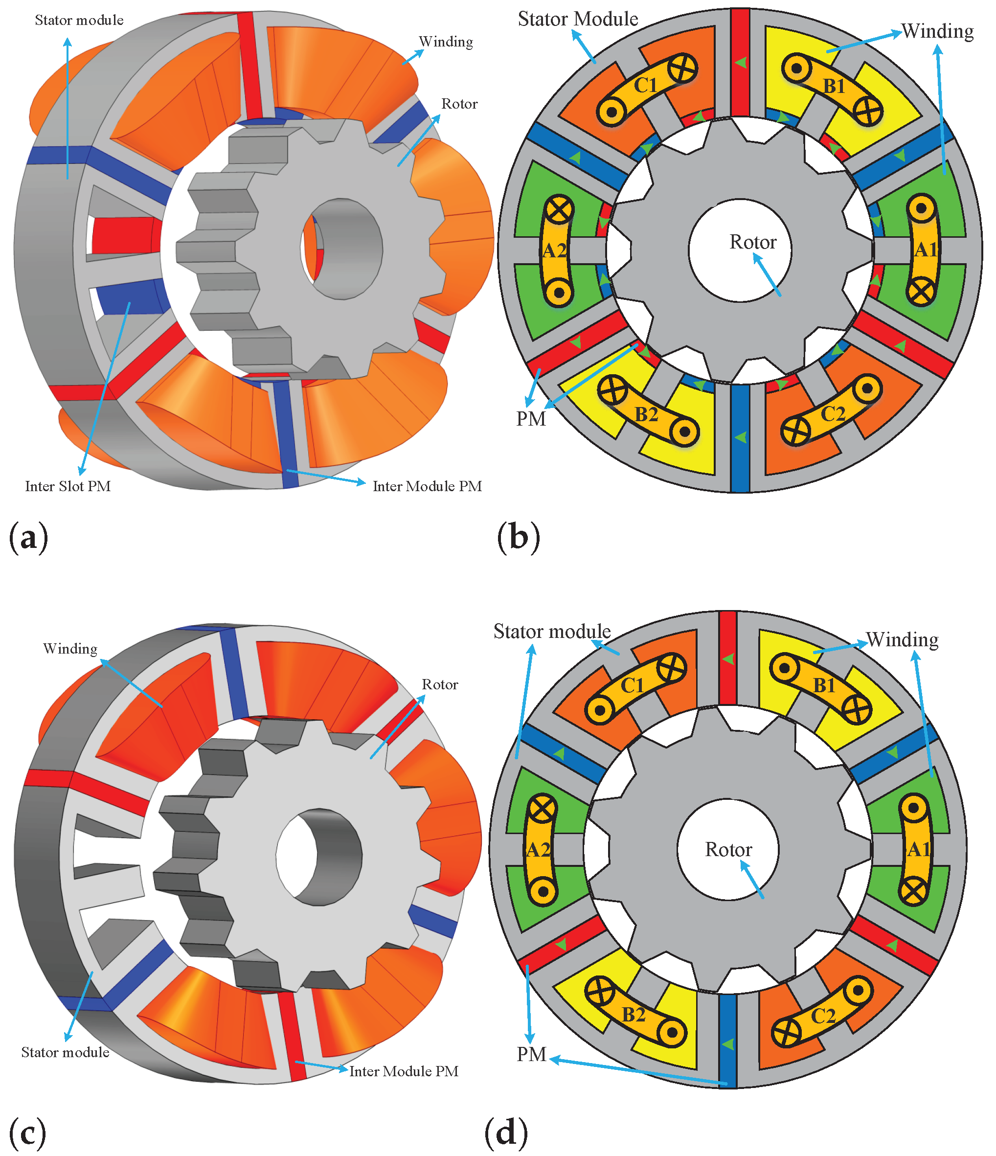
2.1. IMPM’s Operation Principle
2.2. Asymmetric-Biased-Flux Operation
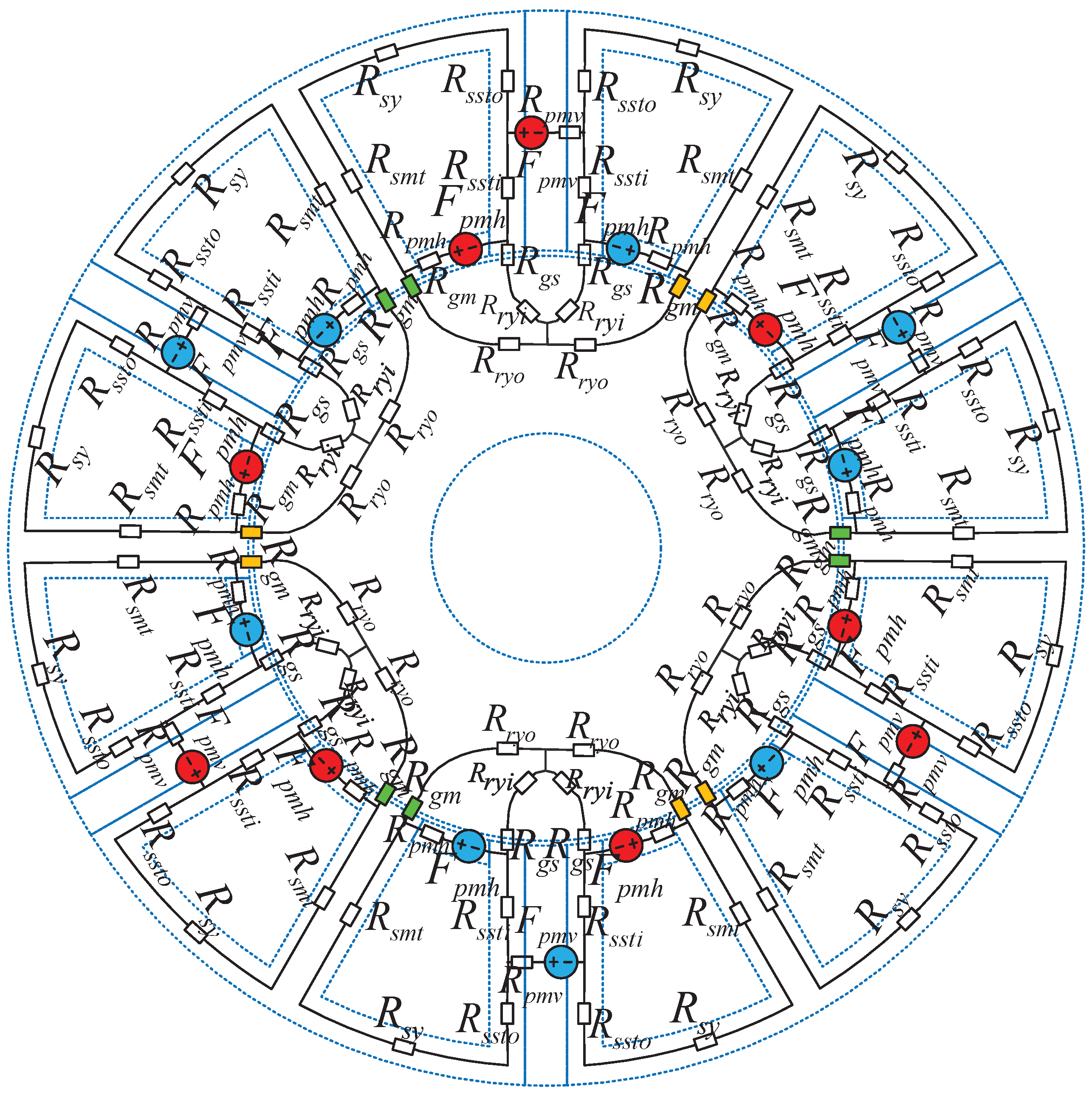
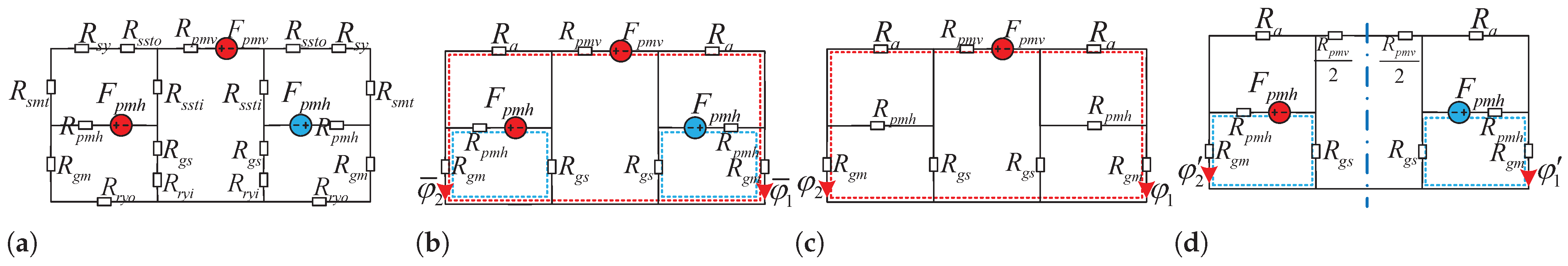
2.3. Mathematical Verification
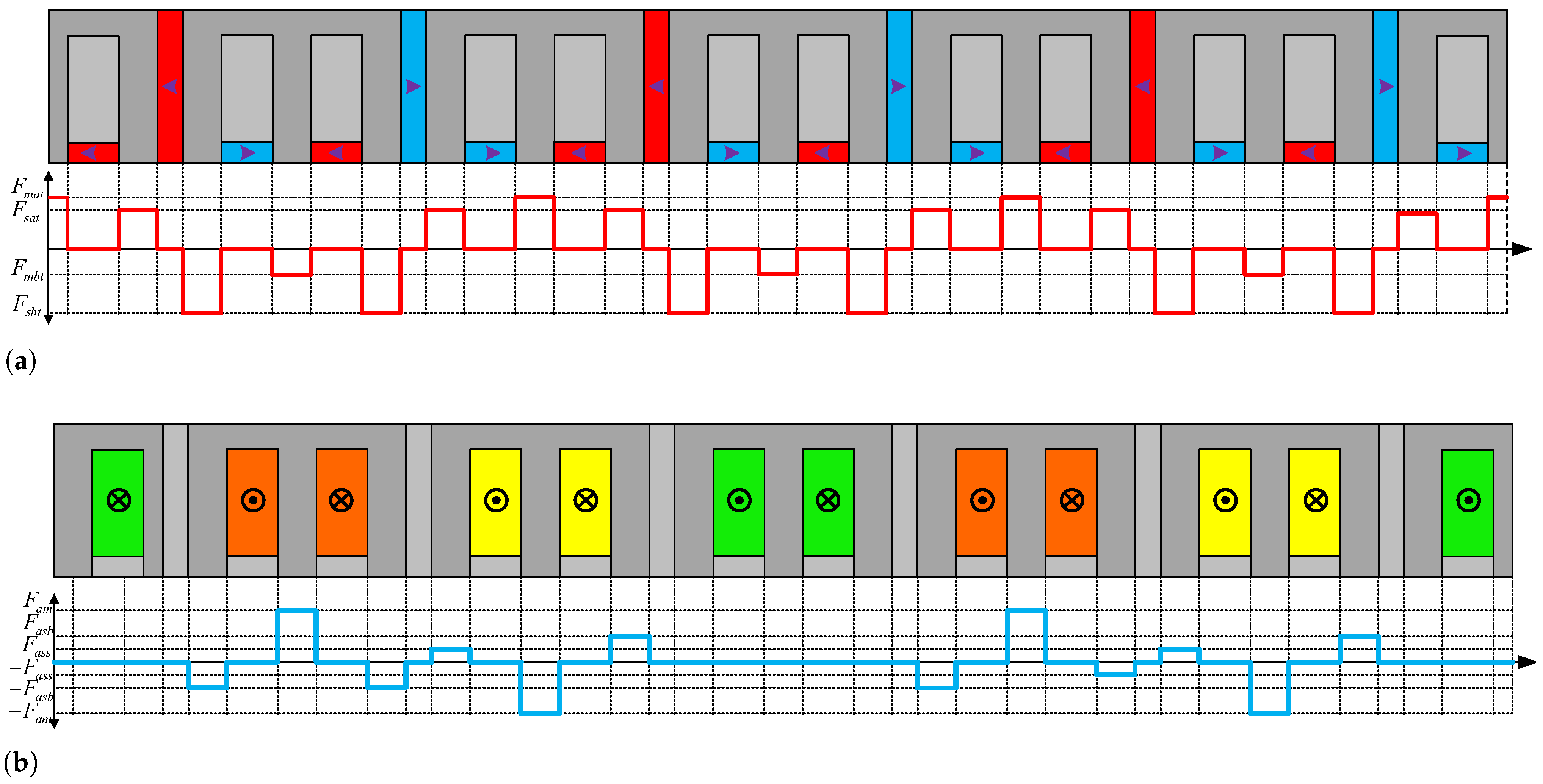
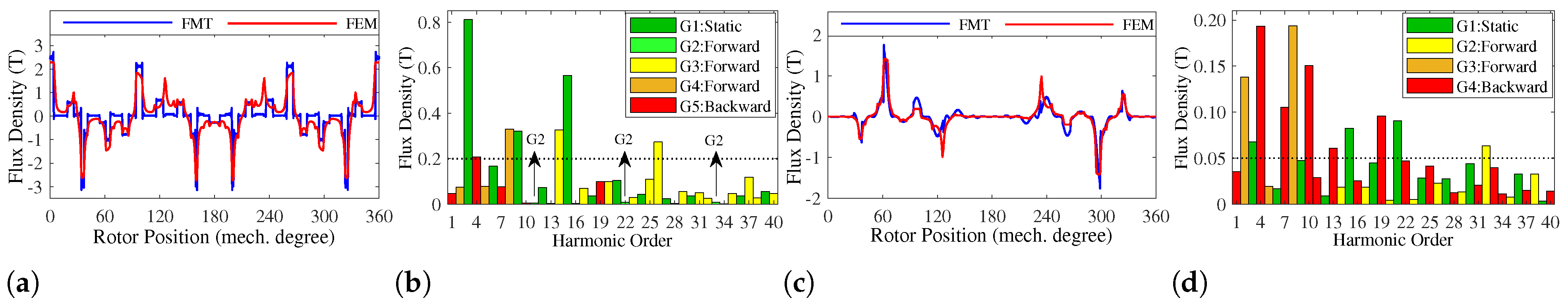
2.4. Space Harmonics
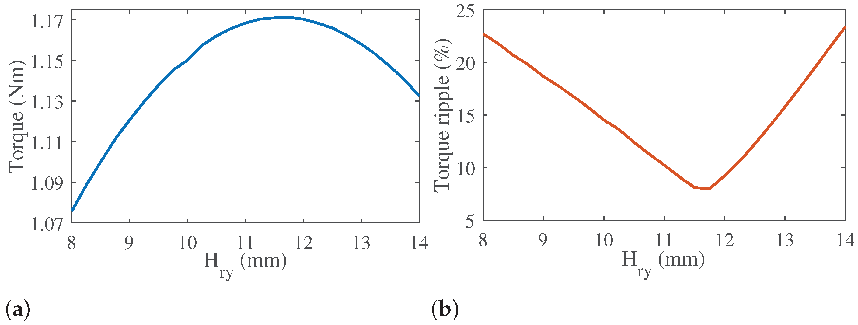
3. Optimization
4. FEA Study
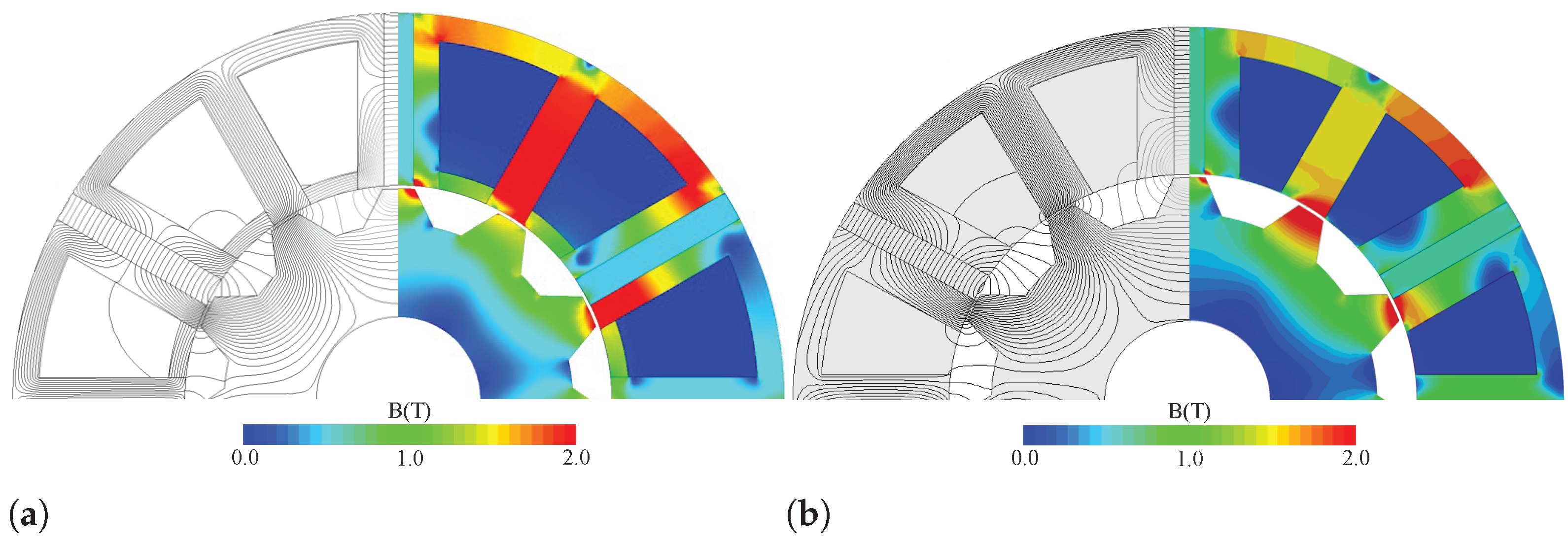
4.1. No-Load Performances
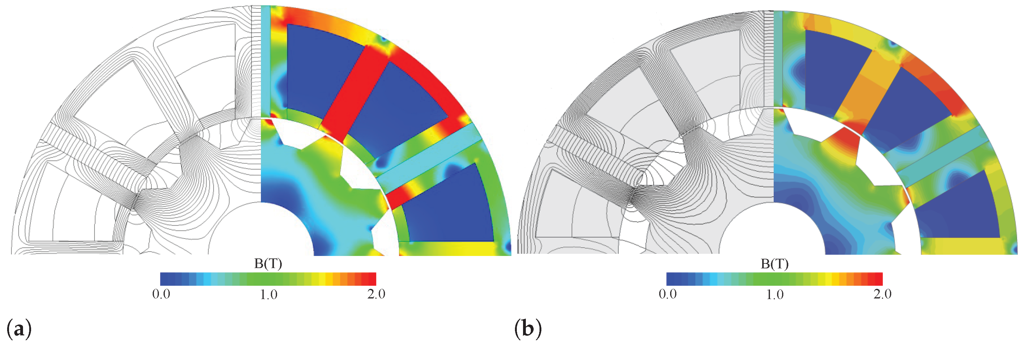
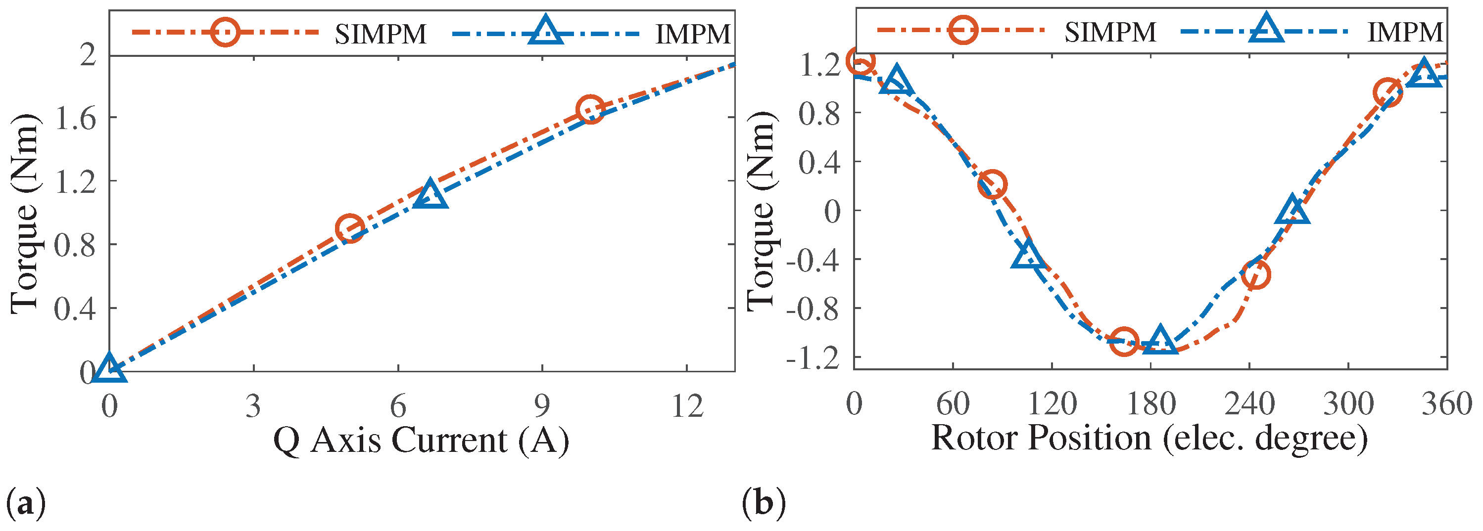
4.2. Full Load
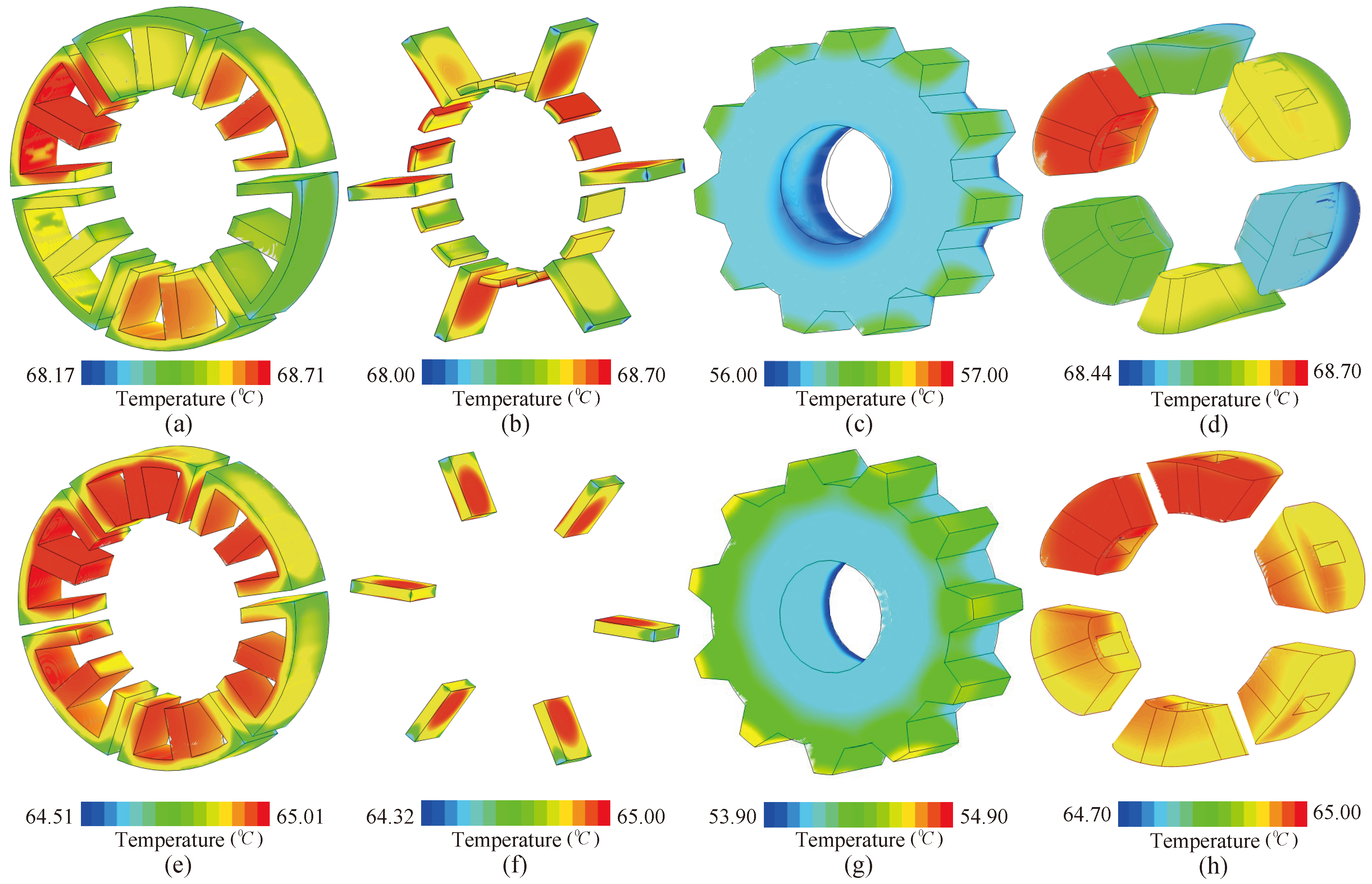
4.3. Thermal
5. Conclusions
Author Contributions
Funding
Data Availability Statement
Conflicts of Interest
References
- Wang, Q.; Zhao, X.; Niu, S. Flux-Modulated Permanent Magnet Machines: Challenges and Opportunities. World Electr. Veh. J. 2021, 12, 13. [Google Scholar] [CrossRef]
- Cai, S.; Kirtley, J.L.; Lee, C.H. Critical Review of Direct-Drive Electrical Machine Systems for Electric and Hybrid Electric Vehicles. IEEE Trans. Energy Convers. 2022, 37, 2657–2668. [Google Scholar] [CrossRef]
- Huang, Z.; Ding, Z.; Pang, M.; Chen, B. Multidisciplinary Design Overview and Comparison for Two Case Studies of High Speed Permanent Magnet Machines. IEEE Trans. Transp. Electrif. 2022, 8, 4242–4254. [Google Scholar] [CrossRef]
- Cheng, M.; Hua, W.; Zhang, J.; Zhao, W. Overview of stator-permanent magnet brushless machines. IEEE Trans. Ind. Electron. 2011, 58, 5087–5101. [Google Scholar] [CrossRef]
- Qu, H.; Zhu, Z.Q. Analysis of split-tooth stator slot PM machine. IEEE Trans. Ind. Electron. 2020, 68, 10580–10591. [Google Scholar] [CrossRef]
- Farahani, E.F.; Kondelaji, M.A.J.; Mirsalim, M. An innovative hybrid-excited multi-tooth switched reluctance motor for torque enhancement. IEEE Trans. Ind. Electron. 2020, 68, 982–992. [Google Scholar] [CrossRef]
- Farahani, E.F.; Baker, N.J.; Mahmouditabar, F. An Innovative H-Type Flux Switching Permanent Magnet Linear Generator for Thrust Force Enhancement. Energies 2023, 16, 5976. [Google Scholar] [CrossRef]
- Sarshar, M.R.; Kondelaji, M.A.J.; Mirsalim, M. Analysis of a Synthesized Slot Permanent Magnet Flux Reversal Motor. In Proceedings of the 2023 3rd International Conference on Electrical Machines and Drives (ICEMD), Tehran, Iran, 20–21 December 2023; pp. 1–4. [Google Scholar] [CrossRef]
- Gao, Y.; Qu, R.; Li, D.; Li, J.; Zhou, G. Consequent-pole flux-reversal permanent-magnet machine for electric vehicle propulsion. IEEE Trans. Appl. Supercond. 2016, 26, 1–5. [Google Scholar] [CrossRef]
- Liao, Y.; Liang, F.; Lipo, T.A. A novel permanent magnet motor with doubly salient structure. IEEE Trans. Ind. Appl. 1995, 31, 1069–1078. [Google Scholar] [CrossRef]
- Kondelaji, M.A.J.; Mirsalim, M. Segmented-rotor modular switched reluctance motor with high torque and low torque ripple. IEEE Trans. Transp. Electrif. 2020, 6, 62–72. [Google Scholar] [CrossRef]
- Farahani, E.F.; Masoumi, M.; Amirkhani, M.; Kondelaji, M.A.J.; Mirsalim, M. A comprehensive analysis of an axial flux switched reluctance motor with different number of rotor poles. In Proceedings of the 2020 11th Power Electronics, Drive Systems, and Technologies Conference (PEDSTC), Tehran, Iran, 4–6 February 2020; pp. 1–5. [Google Scholar]
- Radmanesh, H.; Farmahini Farahani, E. Performance evaluation of a new modular split-tooth permanent magnet-assisted switched reluctance motor. IET Electr. Power Appl. 2023, 17, 441–451. [Google Scholar] [CrossRef]
- Radmanesh, H.; Farahani, E.F. Analysis of a permanent magnet switched reluctance motor with new arrangements for permanent magnets. In Proceedings of the 2022 13th Power Electronics, Drive Systems, and Technologies Conference (PEDSTC), Tehran, Iran, 1–3 February 2022; pp. 96–100. [Google Scholar]
- Farmahini Farahani, E.; Mirsalim, M. Comprehensive study on divided-teeth and permanent magnet assisted outer-rotor switched reluctance motors. IET Electr. Power Appl. 2020, 14, 2293–2300. [Google Scholar] [CrossRef]
- Lordoglu, A.; Gulbahce, M.O.; Kocabas, D.A. A comprehensive disturbing effect analysis of multi-sectional rotor slot geometry for induction machines in electrical vehicles. IEEE Access 2021, 9, 49590–49600. [Google Scholar] [CrossRef]
- Wu, D.; Shi, J.T.; Zhu, Z.; Liu, X. Electromagnetic performance of novel synchronous machines with permanent magnets in stator yoke. IEEE Trans. Magn. 2014, 50, 1–9. [Google Scholar] [CrossRef]
- Ming, G.; Wu, L.; Zhang, L.; Niu, F.; Yan, Y.; Fang, Y.; Zhu, Z. Comparative study of biased flux PM machines having different stator core segments and armature winding configurations. IEEE Trans. Transp. Electrif. 2022, 8, 3379–3389. [Google Scholar] [CrossRef]
- Amirkhani, M.; Ghanbari, M.A.; Kondelaji, M.A.J.; Mirsalim, M.; Khorsandi, A. Performance Analysis of Outer Rotor Multi-Tooth Biased Flux Permanent Magnet Motors. IEEE Trans. Energy Convers. 2023, 38, 1738–1752. [Google Scholar] [CrossRef]
- Amirkhani, M.; Kondelaji, M.A.J.; Ghaffarpour, A.; Mirsalim, M.; Vaez-Zadeh, S. Study of boosted toothed biased flux permanent magnet motors. IEEE Trans. Transp. Electrif. 2022, 8, 2549–2564. [Google Scholar] [CrossRef]
- Amirkhani, M.; Farahani, E.F.; Mirsalim, M. Study of An Improved Biased Flux Intermodular Permanent Magnet Motor. IEEE Trans. Transp. Electrif. 2023, 10, 4455–4469. [Google Scholar] [CrossRef]
- Afrank, M.; Eikani, A.; Farahani, E.F.; Mirsalim, M. Comparative Study of Alternative-Pole Flux Switching and Inter-Modular Biased-Flux Permanent Magnet Motors. In Proceedings of the 2023 3rd International Conference on Electrical Machines and Drives (ICEMD), Tehran, Iran, 20–21 December 2023; pp. 1–5. [Google Scholar] [CrossRef]
- Cai, S.; Zhu, Z.; Mipo, J.; Personnaz, S. Investigation of novel doubly salient hybrid excited machine with non-overlapped field winding. IEEE Trans. Energy Convers. 2020, 36, 2261–2275. [Google Scholar] [CrossRef]
- Zheng, M.; Zhu, Z.; Cai, S.; Li, H.; Liu, Y. Influence of magnetic saturation and rotor eccentricity on back EMF of novel hybrid-excited stator slot-opening permanent magnet machine. IEEE Trans. Magn. 2018, 54, 1–5. [Google Scholar]
- Amirkhani, M.; Mirsalim, M. An improved biased-flux doubly salient shifted permanent magnet motor. In Proceedings of the 2022 13th Power Electronics, Drive Systems, and Technologies Conference (PEDSTC), Tehran, Iran, 1–3 February 2022; pp. 619–623. [Google Scholar]
- Kim, H.K.; Hur, J. Dynamic characteristic analysis of irreversible demagnetization in SPM and IPM type BLDC motor. Trans. Ind. Appl. 2016, 53, 982–990. [Google Scholar] [CrossRef]


| Group | Pole Pairs | Mech. Speed | Harmonic Orders | Direction |
|---|---|---|---|---|
| 1 | 0 | Static | ||
| 2 | Forward | |||
| 3 | Forward | |||
| 4 | Forward | |||
| 5 | Backward |
| Group | Pole Pairs | Mech. Speed | Harmonic Orders | Direction |
|---|---|---|---|---|
| 1 | 0 | Static | ||
| 2 | Forward | |||
| 3 | Forward | |||
| 4 | Backward |
| Group | Harmonic Orders | Torque Contribution | Sum |
|---|---|---|---|
| 1 | 3 (), 6 () 15 (), 21 () | 10.7% (), 3.2% () 46.7% (), 4.9% () | 65.5% |
| 2 | 11 () 22 () 33 () | 0.01% () 0.1% () 0.1% () | 0.2% |
| 3 | 14 () 25 () 26 () 37 () | 19.6% () 2.2% () 7.5% () 3.5% () | 32.8% |
| 4 | 2 () 5 () 8 () | 2.9% () 2.1% () 40.0% () | 45.0% |
| 5 | 4 () 7 () 9 () | −15.1% () −4.6% () −15.3% () | −35.0% |
| Symbol | Value | ||
|---|---|---|---|
| SIMPM | IMPM | ||
| Rotor tooth height (mm) | 4.38 | 4.63 | |
| Rotor yoke width (mm) | 11.23 | 13.45 | |
| Stator yoke width (mm) | 3.14 | 3.26 | |
| Horizontal PM height (mm) | 2.10 | - | |
| Vertical PM angle (deg.) | 8.10 | 6.99 | |
| Rotor tooth angle (deg.) | 8.88 | 7.44 | |
| Rotor slot angle (deg.) | 9.39 | 13.37 | |
| Stator side tooth angle (deg.) | 6.93 | 8.96 | |
| Stator middle tooth angle (deg.) | 11.58 | 12.94 | |
| Parameter | DSPM [23] | TBFSPM [20] | HESSPM [24] | PMaSRM [6] | Sh-BFPM [25] | SSPM [5] | IMPM [21] | SIMPM | |
|---|---|---|---|---|---|---|---|---|---|
| Volume | Core volume (mL) | 159 | 139 | 139 | 139 | 139 | 139 | 139 | 139 |
| PM volume (mL) | 7.7 | 8.6 | 5.5 | 2.2 | 11.7 | 6.2 | 12.0 | 12.6 | |
| Stack length (mm) | 25 | 20 | 20 | 20 | 20 | 20 | 20 | 20 | |
| Loss | Copper loss (W) | 20 | 3.8 | 15.8 | 15.1 | 5.8 | 9.3 | 6.0 | 6.7 |
| Core loss (W) | N.R. | 0.9 | 1.0 | 16.0 | 2.2 | 10.7 | 3.6 | 3.7 | |
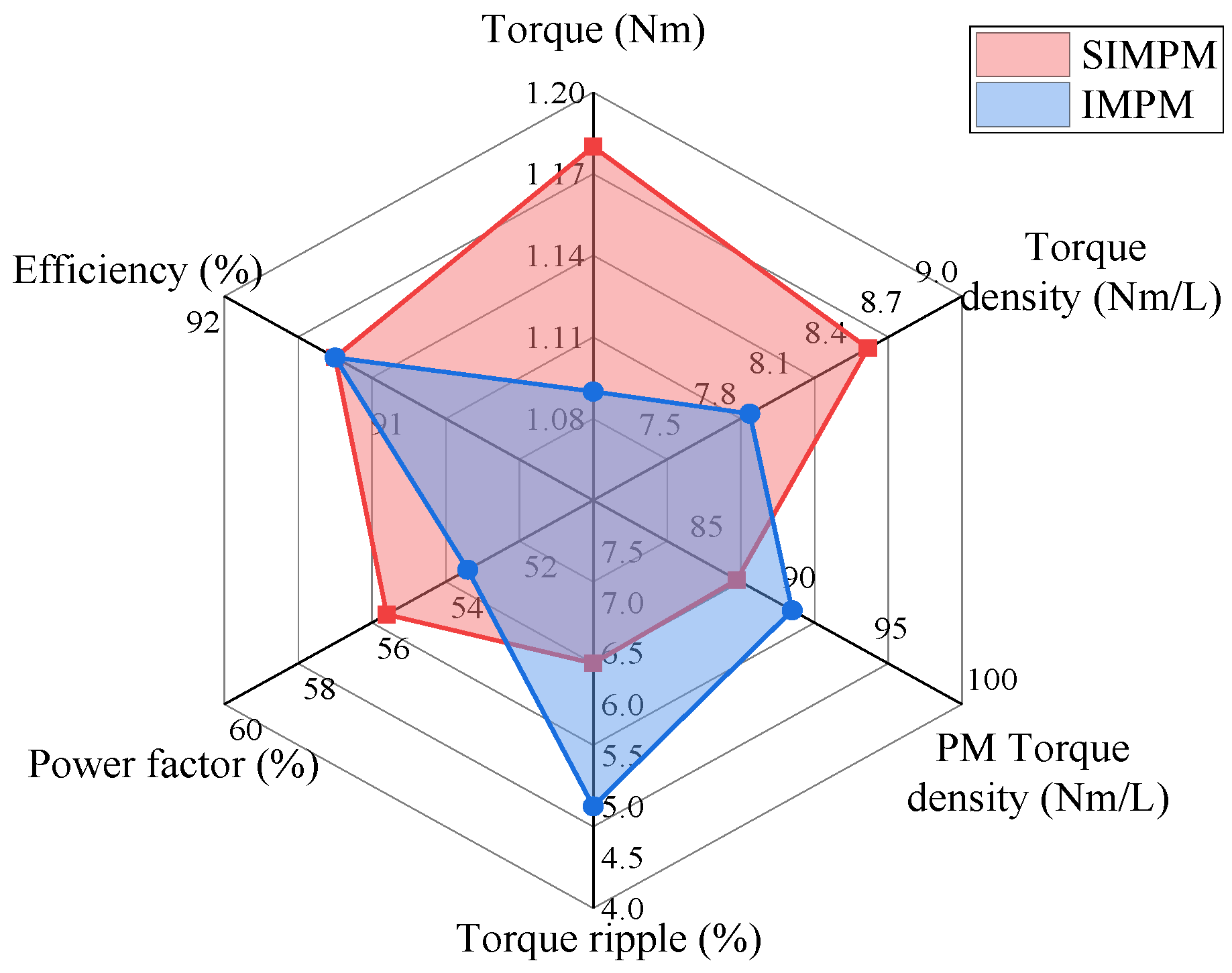
| Electromechanical performance | Average torque (Nm) | 0.98 | 0.77 | 0.69 | 0.67 | 1.0 | 1.18 | 1.09 | 1.18 |
| Torque ripple (%) | 23.5 | 17.5 | 15.7 | 119.2 | 17.8 | 7.0 | 5.0 | 6.4 | |
| Torque density (Nm/L) | 6.16 | 5.54 | 4.96 | 4.82 | 7.19 | 8.49 | 7.85 | 8.49 | |
| Torque per PM volume (Nm/L) | 127.3 | 89.5 | 125.5 | 304.5 | 85.5 | 190.3 | 90.8 | 93.7 | |
| Ang. speed (rpm) | 400 | 400 | 400 | 900 | 900 | 900 | 900 | 900 | |
| Electrical performance | Power factor (%) | 38.0 | 29.7 | 41.2 | N.R. | 58.1 | 17.2 | 53.4 | 55.6 |
| Output power (W) | 33.9 | 32.3 | 28.9 | 63.1 | 94.3 | 111.2 | 102.7 | 111.2 | |
| Efficiency (%) | 67.3 | 87.3 | 63.2 | 67.0 | 92.2 | 84.8 | 91.4 | 91.4 | |
| Material | Specific Heat (J/kg·°C) | Thermal Conductivity (W/(m·°C)) | |
|---|---|---|---|
| Core | M470-50A | 1.24 | 29.2 |
| PM | NdFeB-N42 | 8.93 | 6.16 |
| Winding | Copper | 116.5 | 400 |
| Frame | Aluminum | 6.9 | 237.5 |
Disclaimer/Publisher’s Note: The statements, opinions and data contained in all publications are solely those of the individual author(s) and contributor(s) and not of MDPI and/or the editor(s). MDPI and/or the editor(s) disclaim responsibility for any injury to people or property resulting from any ideas, methods, instructions or products referred to in the content. |
© 2024 by the authors. Licensee MDPI, Basel, Switzerland. This article is an open access article distributed under the terms and conditions of the Creative Commons Attribution (CC BY) license (https://creativecommons.org/licenses/by/4.0/).
Share and Cite
Afrank, M.; Amirkhani, M.; Farmahini Farahani, E.; Mirsalim, M.; Khorsandi, A.; Baker, N.J. Analysis of a New Asymmetric Biased-Flux Operation for an Inter-Modular Permanent Magnet Motor. Energies 2024, 17, 3459. https://doi.org/10.3390/en17143459
Afrank M, Amirkhani M, Farmahini Farahani E, Mirsalim M, Khorsandi A, Baker NJ. Analysis of a New Asymmetric Biased-Flux Operation for an Inter-Modular Permanent Magnet Motor. Energies. 2024; 17(14):3459. https://doi.org/10.3390/en17143459
Chicago/Turabian StyleAfrank, Mohammad, Mohammad Amirkhani, Ehsan Farmahini Farahani, Mojtaba Mirsalim, Amir Khorsandi, and Nick J. Baker. 2024. "Analysis of a New Asymmetric Biased-Flux Operation for an Inter-Modular Permanent Magnet Motor" Energies 17, no. 14: 3459. https://doi.org/10.3390/en17143459