Review

Optimal Electric Motor Designs of Light Electric Vehicles: A Review

Institute of Mechatronics and Information Systems, Lodz University of Technology, 90-537 Lodz, Poland
Energies 2024, 17(14), 3462; https://doi.org/10.3390/en17143462
Submission received: 7 May 2024 / Revised: 29 June 2024 / Accepted: 11 July 2024 / Published: 14 July 2024
(This article belongs to the Special Issue Energy, Electrical and Power Engineering 2024)

Abstract

:
This paper summarizes the results of numerous studies aimed at improving the operating characteristics of electric motors used in light electric vehicles (LEVs). This review focuses on four types of electric motors that can be installed in the drive wheel rims of LEVs. Due to the availability of new magnetic materials and the use of advanced techniques for optimizing the design of electric motors, new motor topologies have emerged. The latest generation motors have been shown to be more efficient, have higher torque density, and generate less torque ripple. This paper indicates and discusses current trends in the topology of electric motors designed for LEV drives. In this context, the effectiveness of the proposed design modifications in terms of selected motor operational characteristics was assessed. The proposed new topologies were compared with commercial solutions, also in terms of the possibility of improving their operational parameters.

1. Introduction

The concept of using electric motors to power vehicles without the need for horses or human muscle first appeared in the 1820s and 1830s [1]. Initially, electric vehicles had limited popularity due to the limited capacity of batteries for storing electricity. Additionally, manufacturers faced significant competition from gasoline-powered vehicles. The widespread availability and low cost of fossil fuels, lobbying by oil companies, and the overall cost of cars are key factors contributing to the popularity of gasoline-powered vehicles both a century ago and today. At the beginning of the twentieth century, gasoline-powered cars were even three times cheaper than electric cars [1]. While the price difference may not be as significant today as it was in the early 20th century, it still exists, and electric cars are generally more expensive than gasoline-powered cars with similar specifications. The popularity of electric and hybrid vehicles has been growing in recent years, driven by rising fuel costs resulting from global geopolitical tensions and the trade policies of major oil producers. Moreover, due to the introduction of stricter requirements limiting the production of harmful substances, manufacturers of gasoline cars are facing increasing demands. Therefore, climate change and greenhouse gas emissions are subjects of great debate worldwide. Electric vehicles are considered the most effective alternative for achieving zero emissions compared to conventional gasoline-powered vehicles. Estimates suggest that electric car sales could reach hundreds of millions of units by 2030 and will vary regionally [2]. The Chinese market is projected to represent around 48% of the global electric vehicle market [3]. Beyond 2030, the market share of electric autonomous vehicles is expected to grow rapidly, with forecasts suggesting it could reach up to 20% of total EV sales by 2040 [4]. However, global sales of plug-in cars are expected to decline after 2030, with the Chinese market maintaining its dominance [5].
Electric vehicles have both advantages and disadvantages. The advantages of electric vehicles include lower operating costs, reduced maintenance expenses, minimal noise pollution, and easier access to urban areas compared to traditional petrol or diesel vehicles. However, electric vehicles also have several significant disadvantages, including higher initial costs compared to vehicles with traditional gasoline engines; the necessity of purchasing a new battery pack to store energy from the traction motor within a specified period of time; the high cost of disposing of old battery packs; the need for a heavy battery pack in vehicles with long ranges; and the limited range of the vehicle without battery charging. Fast charging stations can reduce charging times to 30 min, while using standard electric charger connections in private homes may require several hours.
The use of electric motors in electric vehicle drives is widely discussed and compared in the literature [6,7,8,9,10,11,12]. Various motor design solutions are analyzed based on operating conditions, vehicle range, and other specific requirements. These requirements include, for example, rapid speed changes while maintaining high efficiency; availability of increased torque for hill climbing; ability to work for long periods under high loads; offering high power at low speeds; overload capability; light construction of the vehicle; low moment of inertia; and cost-effectiveness.
In this review article, the author summarizes recent research findings on the design of electric motors used in light electric vehicles. The term light electric vehicle (LEV) refers to a wide range of vehicles, electrically powered, used to travel relatively short distances and for urban or suburban commutes. An LEV is a vehicle designed for carrying small loads of one or more passengers up to an officially specified weight. We can therefore indicate the following vehicle groups:
-
e-bikes with pedal assistance, e-scooters, electric kick scooters, self-balancing scooters, Segways, mopeds, electric three-wheelers, e-skateboards, and electric unicycles—called Personal Light Electric Vehicles;
-
e-cargo bikes for goods transport (e-rickshaws);
-
Mobility scooters, microcars, golf cars, BSO-buses (electric child carrier).
The following has been accepted:
-
e-bike vehicles with pedal assistance have a maximum construction speed of 25 km/h, the maximum mass in running order (mass of the vehicle including batteries without load) should be less than 55 kg, the maximum total mass in running order is approximately 200 kg, and the maximum width of the vehicle is 0.75 m;
-
e-cargo bike vehicles for goods transport have a maximum construction speed of 25 km/h, the maximum mass in running order (mass of the vehicle including batteries without load) should be less than 55 kg, the maximum total mass in running order is approximately 140 kg, and the maximum width of the vehicle is 0.75 m;
-
Mobility scooter vehicles have a maximum construction speed of 25 (even up to 45 for microcars) km/h, and the maximum mass in running order (mass of the vehicle including batteries without load) is greater than 55 kg but does not exceed 350 kg, maximum total mass in running order is approximately 550 kg, and the maximum width of the vehicle is 1 m;
-
The above-mentioned groups of vehicles are powered by electric motors with a power output of several hundred W (Personal Light Electric Vehicles) up to 3–4 kW (microcars, BSO-buses);
-
No license is needed for users of a large portion of these vehicles;
-
Vehicles are powered by an internal battery or are additionally supported by the power of human muscles.
The purpose of this investigation was to determine the appropriate motor topology and materials used in the building of the magnetic circuit. Although this article does not include an overview of developments in the design of systems that power electric motors, the literature clearly shows that these systems are crucial. Many scientists are exploring the topic of motor topology, obtaining interesting results. In their works, they use efficiency maps to demonstrate how control parameters affect an electric motor’s performance [13,14,15]. This review article is divided into the following sections: Introduction, Types of electric motors used in EV drives, A review of LEV motor designs, including topologies that improve operational performance, and Discussion and Conclusions.

2. Types of Electric Motors Used in EV Drives

Key Factors and Parameters to Consider When Selecting an Electric Motor for an Electric Vehicle

Electric vehicles can be classified into several groups based on selected criteria [10,16,17]. Each group can be matched with the most suitable types of electric motors based on factors such as the electric motor price relative to the price of the EV, motor performance, efficiency, and other important factors. Electric motors used in electric vehicles are typically categorized into three main groups: DC motors, induction motors (ACIM), and synchronous motors (SM), including those with permanent magnets (PMSM). Detailed descriptions of their structure and key operational parameters can be found in the literature [18,19,20,21,22,23,24,25,26,27,28,29,30,31,32,33,34,35,36,37,38,39,40]. When selecting an electric motor for a specific type of electric vehicle, it is crucial to consider numerous significant factors.
  • The amount of power and torque generated is directly related to the power-to-weight ratio. A higher value of this ratio will lead to increased speed and acceleration of the electric vehicle.
  • Power density influences space usage by addressing the question of whether a motor can be built to fit into a particular space.
  • Peak power output is the maximum power that an electric motor can generate in a short period of time.
  • Motor efficiency has a direct impact on the vehicle’s operational range.
  • The battery and electronic drive system are selected based on the motor’s voltage and current specifications.
  • The motor’s application area is determined by its cooling technology (air-cooled or liquid-cooled), which is crucial for improved heat management and performance.
The first factor mentioned above is one of the most important in determining the level of technology used in the production of electric motors. Recent developments have highlighted the technological advances in the production of electric motors for electric vehicles. The IDTech Ex report provides a detailed assessment of these changes, emphasizing the current technology landscape and potential challenges [41]. The report analyzed key parameters of electric motors used in various electric vehicles, including light EVs, electric cars, trucks, and buses. The study focuses on electric power units found in new vehicles sold over the past eight years. The motors examined range in power from hundreds of watts to approximately 630 kW and weight from 1 kg to 350 kg—see Table 1. It is important to note that no conventional DC motors are included in the list.
The multimedia presentation by IDTechEx Group highlighted the results of comprehensive research on electric motors for powering EVs [42]. The presentation covered five types of motors: ACIM, PMSM (permanent magnet synchronous motor), PMSR (permanent magnet switched reluctance motor), WRSM, and BLDC (brushless DC motor).
The parameters for the comprehensive evaluation were divided into four groups: operating parameters, production complications, ease of adjusting the existing operating parameters of the electric motor, and structure-related factors (such as power and torque densities). The overall rating considers parameters like controllability, motor cost, efficiency, ease of manufacturing, noise level, power density, reliability, scalability, and torque density. Each parameter was rated on a scale of 1 to 10, with 1 being the lowest and 10 being the highest. The detailed results of these evaluations are presented in Table 2 and Figure 1.

3. A Review of LEV Motor Designs, Including Topologies That Improve Operational Performance

This review analyzed the construction of four types of electric motors, taking into account the above-mentioned criteria and specifications of LEVs. The selection was made based on the nominal power range (from several hundred W to three to four kW) and weight (from approximately 1 kg to 20 kg) of a single electric motor intended for the LEV drive. The IDTechEx report, which outlines the development trends (from 2024 to 2034) of many types of electric motors intended for use in electric vehicles, was considered in the selection process [41].

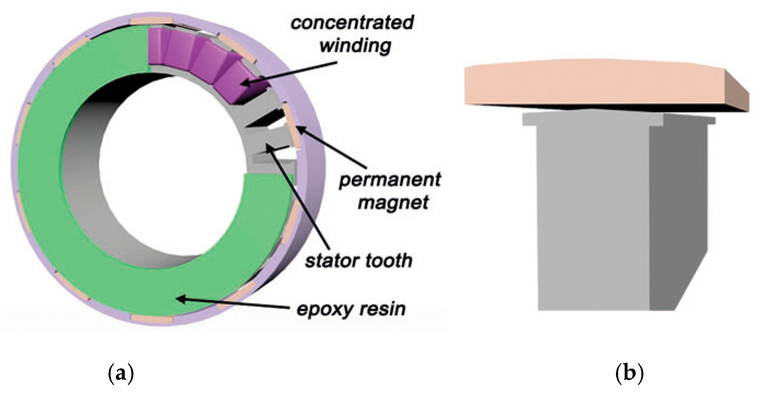
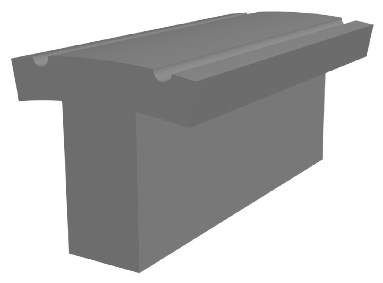
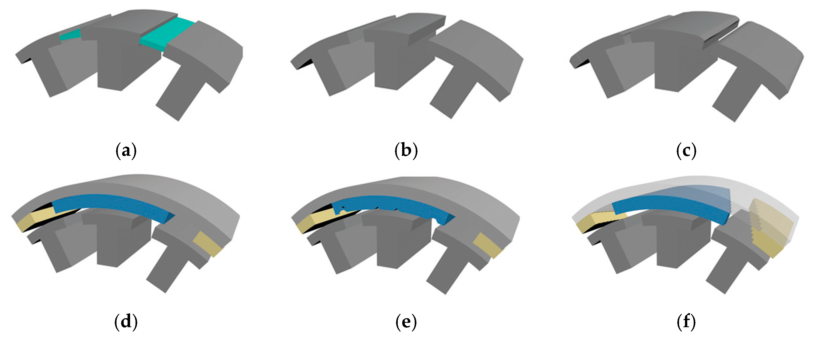
3.1. In-Wheel Motors with Surface-Mounted Permanent Magnets

In recent years, in-wheel motors have gained popularity due to the integration of the electric motor with the wheel. This integration eliminates the need for a drive transmission system, significantly improving the efficiency and reliability of the design. Researchers have studied several types of electric motors, including permanent magnet motors, magnetic gear motors, switched reluctance motors, and wireless motors. In low-speed electric vehicles, permanent magnet in-wheel motors are often used, where the external rotor can be embedded into the wheel [43,44]. The main advantages of this electric motor design are its double-salient structure and good thermal stability, which is ensured by easy cooling.
A 20-pole–24-slot surface permanent magnet synchronous motor for low-speed in-wheel direct drive is investigated in [43]. The motor’s geometry is shown in Figure 2. This is one of the potential solutions used in such a drive [45,46]. The advantage of this solution is that it reduces the use of PM material while maintaining performance during continuous operation.
Electric motors developed for powering electric vehicles (EVs) are currently designed to minimize the use of permanent magnet (PM) materials by introducing new topologies. Therefore, the possibility of using a design with an external rotor should be considered, but this may lead to a magnetic imbalance. This issue can be mitigated by utilizing a proper combination of pole-slot configurations and winding connections [45]. A study by researchers [43] has shown that in such cases there are limitations related to the imposed outer diameter of the motor and the axial length of the core. The dimensions must be carefully adjusted to fit a 16-inch aluminum rim. One of the key features of the proposed electric motor type is thermal stability. To achieve this stability, the authors recommend using segmented stator cores. Additionally, rectangular cross-section conductors were incorporated into the design to optimize the available slot area, thereby reducing current density and Joule loss in the winding. All stator components were enclosed in epoxy resin, providing structural strength and a path for heat transfer from the windings to the housing. The authors suggested the possibility of utilizing an uneven air gap, which reduces cogging torque, torque ripple, and induced voltage harmonics at no-load conditions. This is one of the well-known methods used to reduce vibrations, as confirmed in the work of other researchers [47,48,49,50,51,52,53,54,55,56]. In the proposed motor geometry, the use of an uneven air gap proved to be very effective, as it lowered the cogging torque amplitude fourfold [43]. This method also effectively reduced the torque ripple, which is associated with rotational smoothness. The amplitude of the torque ripple was reduced by half [43]. These design achievements significantly improved the comfort of driving an electric vehicle powered by this type of motor. Another advantage of the proposed approach is the motor’s extremely high efficiency, which reaches 94%. It should be noted that the proposed approach performs well across a variety of speeds and torque ranges [43]. The effectiveness of the proposed solution stems from the fact that the uneven air gap allows for interference in the spatial distribution of the electromagnetic field in the air gap. The theoretical basis related to the reduction in higher harmonics in the air gap can be found in the works of other researchers [57]. The literature contains examples of different strategies for creating an air gap with variable thickness than those described above—see Figure 3 and Figure 4.
The techniques mentioned above address interference in both the geometry of the stator teeth and the shape and size of permanent magnets (PMs) in the rotor. In [58], the authors studied the impact of the size of the so-called not fully magnetized zone, which is essentially a recess in the shape of a stator tooth, as shown in Figure 3. The authors achieved a 60% reduction in cogging torque by carefully optimizing the shape and size of this recess. Similar results were reported in [59], where the authors managed to reduce cogging torque by up to 85%. A similar approach to reducing cogging torque was also presented in [60], where two recesses were created in the head of the stator tooth. By examining the optimal position and size of these recesses, a 30% reduction in cogging torque was achieved. Another modification of the topology was recommended in [61], where the authors investigated the influence of size, location, and the material used for creating the stator bridge, also known as a wedge—see Figure 4a. The stator bridge connects the heads of neighboring stator teeth and is located next to the air gap. The authors managed to reduce the cogging torque by three times while increasing the average torque by 5%. Another team of researchers studied the influence of the width of the stator tooth heads on the reduction in the cogging torque—see Figure 4b. During the study, two versions of the solutions were tested, one with the same width of tooth heads and the other examining the influence of asymmetry in the width of the tooth heads in adjacent teeth [62]. By selecting the head size, the researchers achieved a fivefold reduction in cogging torque. Even better results were achieved by pairing teeth with different head widths. More approaches to modulating the thickness of the air gap can be found in the literature. The solution proposed in [43] resulted in a considerable reduction in both cogging torque and torque ripple. In another study [63], the authors investigated four scenarios of air gap variation profiles, as shown in Figure 4c. They also highlighted the significant influence of the air gap profile on the obtained results, showing a several-fold reduction in cogging torque and a corresponding increase in average torque.
Another technique to reduce torque ripple or cogging torque is to modify the design specifications of permanent magnets (PMs), which can yield interesting results. A study conducted by the research team [62] showed that adjusting the angle of the magnet pole can reduce the cogging torque by six times. Additionally, shaping the edge of the magnet helped reduce the cogging torque by a factor of five when adjacent magnets come into contact with each other. A similar study was described in [64], where they analyzed two permanent magnet synchronous motors (PMSM): one with 24 poles and 72 slots, and another with 6 poles and 36 slots. In these studies, the widths of permanent magnets placed adjacent to one another were optimized to reduce cogging torque and torque ripple. In both scenarios, the optimization process successfully generated permanent magnet width combinations that effectively eliminated cogging torque and significantly reduced torque ripple. For the 24-pole/72-slot motor, the torque ripple was reduced by more than ten times, while the average torque decreased by about 5%. In the second scenario involving a 6-pole/36-slot motor, a six-fold reduction in torque ripple was achieved without compromising the average torque. Similar results have been reported by other researchers. In [65], the authors detailed the findings of a study on magnet pole arc reduction for an 8-pole/12-slot motor. An example of this solution can be seen in Figure 4d. Finding the optimal width of the magnet arc allowed for a seven-fold reduction in cogging torque while maintaining the average torque level. Moreover, the torque ripple amplitude has been reduced three-fold, and the back EMF waveform has been adjusted closer to a sinusoidal waveform. A slightly modified strategy was adopted by another research team, which presented the results of their research in [66]. Instead of seeking the optimal width of permanent magnets, each magnet was divided into pieces separated by an air gap. From a design standpoint, such a segmented group of permanent magnets is comparable to a single magnet of the same width. The research resulted in a reduction in cogging torque amplitude by 97% or 90%, depending on the number of segments. Interesting research results on an external rotor motor can be found in [67]. The authors’ primary goal was to determine Joule losses in individual motor parts and assess motor efficiency. The external rotor of the tested motor was equipped with 31 pairs of permanent magnets. The spacing of the magnets was chosen to ensure that the back EMF waveform closely resembled a sinusoid. Air gaps were present between the magnets, and additional air gaps were introduced in the rotor yoke, dividing it into sections with one air gap between each pair of poles. The stator teeth had trapezoidal recesses at their heads, following the concept shown in Figure 3. As a result of the study, the motor efficiency increased from 83% (in the version without additional air gaps in the rotor yoke) to 86% (in the version with slots). The same type of electric motor underwent further analysis and design modifications [68]. The width of the air gaps between permanent magnets was adjusted to discover the optimal slot/pole number combinations. The research revealed that widening the air gap between permanent magnets leads to a tenfold reduction in both cogging torque and torque ripple. It was also observed that wider gaps resulted in smaller amplitudes of both torques. Conversely, narrower gaps and an increased number of pole pairs reduced the amplitude of both torques. Unfortunately, wider gaps led to lower motor efficiency, regardless of the number of pole pairs.
It is well known that shaping the surface of permanent magnets minimizes the content of higher harmonics of the magnetic field in the air gap, thereby reducing parasitic torques. Significant research in this field has been documented in the literature [69]. An example design related to this research is shown in Figure 4e. The literature discusses the concept of creating notches in the surface of the permanent magnet, which is similar to shaping tooth surfaces by creating recesses—see Figure 3. The research team that addressed this problem designed the shape, geometric dimensions, and position of the permanent magnet notches to ensure that the back EMF waveform contains a minimum number of higher harmonics. This design effectively eliminated torque ripples, reducing the ripple amplitude by several dozen times, and decreasing cogging torque to the same level. After shaping the permanent magnets (PMs), the average torque generated by the motor remained constant, which is a significant advantage of this technique. Another effective way to regulate the higher harmonic content of the magnetic field in the air gap is to use skewed permanent magnets—see Figure 4f. Studies using this technique have shown a significant reduction in cogging torque and a decrease in the ripple torque amplitude [70,71]. By adjusting the PM skew, specific harmonics of the magnetic field can be reduced, resulting in lower cogging torque and torque ripple. In a study [70], the results of two experiments are presented. In the first experiment with an 8-pole/24-slot motor, after eliminating the first two harmonics, the cogging torque was reduced by 98%. In the second experiment with a 6-pole/27-slot motor, the torque was reduced by 86% by eliminating the second harmonic. Another team of researchers further developed this concept by proposing a sinusoidal PM shape [71]. In practice, the desired shape of permanent magnets was achieved by combining multiple magnets of different sizes, resulting in a significant reduction in magnet volume. Additionally, an almost sinusoidal back EMF waveform was obtained, the cogging torque was decreased by 86%, and the torque ripple was reduced by 75%. Importantly, the average torque generated by the motor remained constant. The proposed solutions were compared to the results obtained from a motor with skewed magnets. The motor with skewed magnets exhibited significantly lower cogging torque, but torque ripples were 50% higher. Research conducted in this area, with a slightly modified technique for obtaining the skew of permanent magnets, was described in [72]. An alternative approach was to use multiple magnets with a length shorter than the rotor package, allowing for the PM skew effect to be achieved in a different way. A group of two to five PMs was examined, each rotated by a specific angle relative to the others. As a result of the work carried out, the amplitude of the cogging torque was reduced by 5–7 times, depending on the combination of displacements of the individual magnets in the group.
As mentioned earlier, torque ripple reduction can be achieved by adjusting the air gap thickness using the designs shown in Figure 2, Figure 3 and Figure 4. Another approach to reducing torque ripple is by considering a modified motor topology, as discussed in [73]. In their research, the authors focused on improving the design of Vernier permanent magnet machines, which utilize ferrite magnets in both the stator and rotor. The research was conducted in two stages. In the first stage, changes were made to the number of stator teeth (Z), rotor pole pairs (Pr), and stator winding MMF pole-pair number (Ps) based on a proposed relationship [74]. Two configurations labeled as Ps/Z/Pr were analyzed, with the first configuration represented by Ps/Z/Pr = 1/20/21 and the second by 5/24/19. The second design showed a fivefold reduction in torque ripple. In the second stage of the research, the results were obtained for:
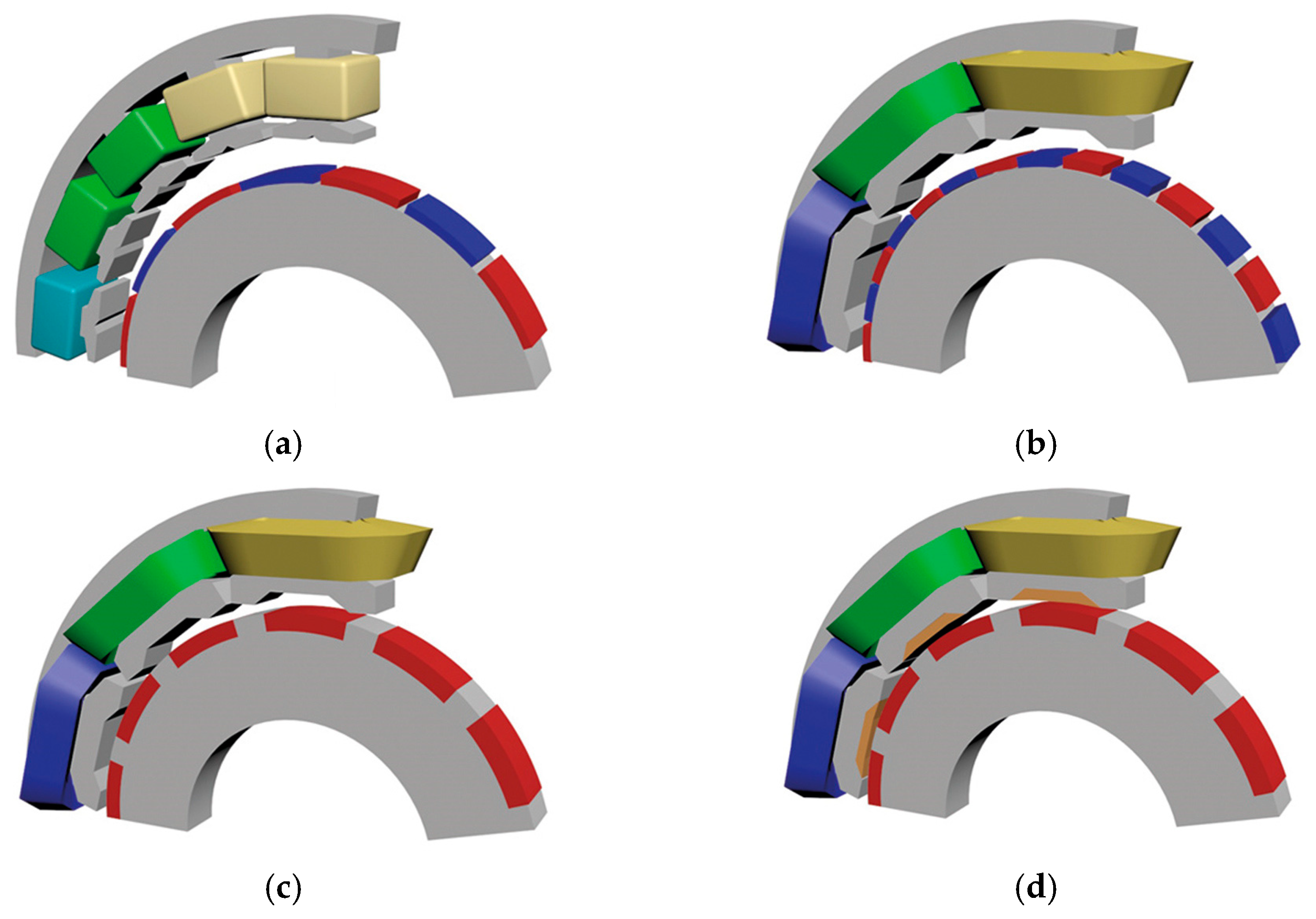
  • Optimized 27-slot, 12-pole-pair regular PMSM with ferrite magnets or NdFeB magnets—Figure 5a;
  • Optimized split-tooth, 12-slot, 19-pole-pair, regular permanent magnet Vernier motor with NdFeB magnets—Figure 5b;
  • A 12-slot, 24-tooth, 19-pole-pair, consequent-pole permanent magnet Vernier motor with ferrite magnets—Figure 5c;
  • A 12-slot, 24-tooth, 19-pole-pair, consequent-pole permanent magnet Vernier motor with stator-assisted ferrite magnets—Figure 5d.
The torque density of the different motor versions varied significantly. The best approach (#4) showed almost three times higher torque density than solution #1 and a 34% higher static moment compared to another optimized conventional PMSM of the same volume. The optimal approach also had a very low peak-to-peak cogging torque (only 4% of the maximum torque) and 20% lower total losses. Further analysis comparing the standard VPM (Figure 5b) and consequent-pole VPM (Figure 5c) can be found in [75], while [76] presents research results on the topology of a segmented rotor with flux barriers. The technique used resulted in a 10% reduction in total losses and increased efficiency by 1 to 3%, depending on the motor load.
Permanent magnet Vernier motors are known for their simple topology and high torque density. The high torque density is achieved through the interaction of two torque generation mechanisms. The first torque component is generated by the standard PM machine mechanism, while the second is generated by the magnetic gearing effect. Extensive research has been conducted on these motors in recent years [77,78]. In Ref. [77], the authors compared the performance of PMSM and PMVM motors with an average torque of approximately 1000 Nm. The conducted research on PMVM and PMSM showed similar values of torque per active mass, twice the torque density, a 40% reduction in PM mass, a 15% reduction in total active material cost, and a 40% reduction in cogging torque and torque ripple amplitude. In Ref. [78], various combinations of the number of stator teeth, rotor pole pairs, and stator winding MMF pole-pair number were investigated. The specific values selected had a significant impact on the motor’s average torque and torque ripple amplitude. The values of these parameters varied by 10% depending on the combinations used. Moreover, torque density changed significantly, by up to 40%. As shown in [79], a slight change in the geometry of the stator teeth compared to the solutions used in standard VPM resulted in a considerable improvement in torque density. The authors investigated a prototype design of a spoke-type permanent-magnet Vernier machine (STPMV) with an external rotor—see Figure 6. By adjusting the dimensions of the permanent magnets and the head sizes of the stator teeth, they increased torque density by 30% over typical VPM. Design considerations for this type of electric motor were previously presented by another group of authors [80].
Further tests on the STPMV motor, including the selection of the size and shape of the stator tooth, are presented in [81], while the topology is shown in Figure 7a. The authors investigated the harmonic content of the induction curve in the air gap, considering the dimensions and shape of the stator slots. The analysis led to the proposal of specific dimensions and shape of the stator slot, which resulted in over a 50% increase in the generated average torque. For the recommended topology, the best size ratio of the inner stator diameter to the outer stator diameter was found to be 0.5–0.7. The authors demonstrated that adjusting the thickness of the permanent magnets could reduce torque ripple in the tested motor by 2.5 times. The optimal thickness of the permanent magnets, 2–2.5 mm, also provided the highest average torque. Additionally, the optimal angular width of permanent magnets in the recommended motor topology was determined to be 24–30 degrees. Wider magnets led to lower average motor torque and higher torque ripple. Test results showed that the motor with the selected tooth and permanent magnet sizes showed an 86% lower cogging torque compared to a conventional VPM motor.
Another interesting approach can be found in the literature: the V-shape flux-modulated permanent-magnet (V-FMPM) motor [82]—see Figure 7b. This topology refers to the motor design concept known as the air gap-harmonic-oriented design technique. In the tested scenario, the stator teeth were shaped like those shown in Figure 6a, and their geometric dimensions were optimized. The magnets in the stator were arranged at a specific angle to the air gap. They, together with the stator teeth, were a key component of the “harmonics modulator” of the induction curve in the air gap. In comparison to the initial motor, the dimensional optimization method enhanced average torque by 12% and reduced torque ripple by 50%.
Table 3 summarizes the effectiveness of the described design ideas in improving the operating characteristics of in-wheel motors using surface permanent magnets.

3.2. Axial-Flux Motors

Axial-flux motors are categorized into different groups based on their rotor structure: axial-flux induction motors with a squirrel cage rotor [83,84,85], axial-flux reluctance motors with direction-dependent rotor reluctance [86,87,88,89], axial-flux motors with permanent magnets mounted on the rotor surface, and axial-flux motors with internal permanent magnets integrated inside the rotor.
There are three types of stator structures in axial-flux motors: coreless [90,91,92], slotless [93,94], and slotted [95,96]. Stators are typically made of materials such as stamped laminations [97], amorphous metals [98], hybrid multi-materials [99,100,101], or soft magnetic composites [95,102,103,104]. The stator windings can also be printed on PCBs [90,105,106]. Additionally, these motors may have more than one stator or rotor.
Researchers are focusing on optimizing the geometry of permanent magnets in axial-flux motors, similar to the work undertaken in the design of in-wheel motors with permanent magnets. Research conducted on single-sided axial flux permanent magnet (AFPM) machines has contributed to the reduction in torque ripple, as shown in [107]. The authors used the arc profile for the conventional hexagonal-shaped PM—see Figure 8. The proposed new hexagonal-shaped PM reduced air gap flux density, hence reducing cogging torque and torque ripple. During the study, the authors assumed that the volume of magnets in conventional and proposed hexagonal-shaped magnets would remain constant. In addition to adjusting the magnet’s dimensions, they proposed that its surface be convex, thus modulating the thickness of the air gap between the magnets and the stator teeth. This work resulted in keeping the average torque constant, reducing the THD (total harmonic distortion) coefficient from 1.33% to 0.79%, reducing torque ripples from 18.9% to 12% of the average torque, and reducing cogging torque by over 36%.
A broader scope of research related to rotor topology is described in [108]. The authors’ primary goal was to reduce cogging torque, which is directly related to the reduction in higher harmonic induction content in the air gap. The study focused on an AFPM motor with one stator and one rotor. The motor had permanent magnets placed on the rotor, and their shapes were varied to find the best design. Computer simulation results were analyzed for various magnet configurations, including flat-top trapezoidal magnets, skewed magnets, curved-shaped magnets, and curved skew magnets. The study revealed that the motor with curved skew magnets had the lowest total harmonic distortion (THD) value, which was three times lower than that of flat-top trapezoidal magnets. Additionally, the peak-to-peak cogging torque decreased by more than two times, with a 10% reduction in back EMF.
An interesting study on a single-sided axial-flux motor (AFM) with one rotor and one stator can be found in [109]. The authors explored the concept of eliminating the use of permanent magnets in the design of such motors. The test results showed torque-to-weight ratios based on different excitation types (neodymium-boron magnets, ferrite magnets, and electrical) and air gap thicknesses (ranging from 0.05 to 1 mm). The authors demonstrated that for air gaps thicker than 0.1 mm, the use of neodymium-boron magnets resulted in a torque-to-weight ratio four times higher than with other excitations. The authors also noted that as the air gap thickness decreased, the increase in this ratio compared to electrical excitation was less significant. Specifically, for air gaps thinner than 0.1 mm, a motor with electrical excitation outperformed other solutions in terms of torque-to-weight ratio.
As mentioned earlier, electric motors used in electric vehicle drives should have the highest possible torque density. Research in this area has been conducted, for example, in [110]. A design solution was considered to achieve the maximum power density and average torque. The research focused on an axial-flux permanent magnet motor (AFPM) with a single stator and two rotors. In the tested motor, permanent magnets were installed on the rotor, and overlays made of SMC material were added to them. During the tests, power and torque densities were evaluated for several stator material combinations. The research included a yokeless motor, a motor with a yoke made of grain-oriented material, a motor with a yoke made of non-oriented material, and a motor with a yoke separated into two sections (tooth and yoke). In the last topology, the stator sections consisted of grain-oriented material arranged in various directions. The findings showed that the yokeless motor had a 40% higher power density and 17% higher torque density than the other examined options. In turn, the use of two parts of the stator yoke with different orientations increased both power density and torque density by approximately 2% compared to a yoke made of grain-oriented material.
Another line of research focuses on reducing the mass of permanent magnets while increasing torque density. In [111], the authors presented an innovative concept of rotor construction. They compared two approaches: the yokeless and segmented armature axial-flux permanent magnet motor (YASA) and a parallel magnetic circuit yokeless and segmented armature axial-flux permanent magnet motor (PMC-YASA)—see Figure 9. Both designs were intended for use on a 15-inch wheel hub. The main objective of the research was to minimize total losses in both the core and permanent magnets. While the motor’s dimensions remained constant, the rotor topologies have changed significantly. Instead of using axially magnetized permanent magnets (YASA motor), tangentially magnetized permanent magnets and a radial Halbach array were used. As a result of these modifications, the axial length of the PMC-YASA motor has been reduced compared to the YASA motor. Additionally, the stator teeth, rotor back iron, rotor iron core segments, and the radial part of a yoke were made of a soft magnetic composite material. An added benefit of this proposed solution was that the PMC-YASA motor required 38% less mass of permanent magnets than the YASA motor. The new topology reduced the total harmonic distortion (THD) of the back EMF waveform by half, increased the maximum torque by 9%, and decreased total losses in the rotor iron and permanent magnets by half.
Reducing the bulk of permanent magnets used in motor manufacturing is a significant scientific challenge. In pursuit of this goal, another team of researchers examined the same type of motor (YASA) [112]. The authors studied three motor designs to determine which of them allowed for the highest overloads—examples of topologies are shown in Figure 10. The estimated total power losses generated for a given constant load torque at a specific speed indicated the possibility of overloading the motors. The following topologies were tested: the topology with one and two rotors, and the topology using ferrite and neodymium magnets. The axial length, active diameter, slot depths, and copper volume remained consistent across all three motor topologies. The stator was made of SMC material in all situations.
Research results showed that the motor with neodymium magnets generated more than twice the torque compared to the motor with ferrite magnets. Although the introduction of ferrite magnets considerably reduced the magnet losses, additional copper losses, and total stator core losses, the overall losses increased several times. Based on these observations, the authors concluded that for naturally cooled motors, the single-sided motor has better parameters than the YASA topology. For motors with high torque density and forced cooling, the YASA motor is the preferred option.
The permanent magnet vernier machine (PMVM) is a popular alternative motor topology for low-speed direct-drive applications, such as electric vehicle motors. Compared to radial-flux PMVM, axial-flux PMVM has a compact axial structure and high power density. A study on a single-stator single-rotor PMVM can be found in [113], where the authors focused on improving the geometry of the stator teeth and selecting the dimensions of the permanent magnets in the rotor. As other authors note, the relationship between the dimensions of the specified motor components and the generated torque, as well as the axial forces acting on the rotor, should be taken into account. The authors demonstrated that reducing the height of the stator tooth enhances the axial force but decreases the generated torque while increasing the magnet field arc coefficient increases both the axial forces and the generated torque. In the improved motor design, the radial force was reduced by approximately 18%, while the generated torque was reduced by only 2%.
Research conducted by various teams of scientists goes beyond determining the sizes and shapes of the parts of the magnetic circuit of axial-flux motors that provide the highest possible torque density and motor efficiency. An important factor to consider is the weight of electric motors for solar-powered vehicles, as detailed in [114]. In this research, the authors compared a commercially available single rotor-single stator motor with a coreless multi-disc version with air gap concentrated windings–see Figure 11.
The number of stator disks was varied during the coreless motor testing. Three models with one, two, and three stators were investigated, considering modifications in the number of poles and coils. The tests assumed that the air gap, active volume, PM mass, and steel mass remained constant. The tests showed that the highest torque density was achieved by the motor with three stator disks, while the lowest copper losses were achieved by the motor with 16 poles and 12 coils. In turn, the 32 poles/24 coils combination resulted in the lowest copper mass. Moreover, the proposed coreless motor topology was 40% lighter than the commercially available AFPM motor, while reducing the rated torque by approximately 40%. The proposed solution had the advantage of achieving more than double the rated speed.
Table 4 summarizes the effectiveness of the described design ideas in improving the operating characteristics of axial-flux motors for LEVs.

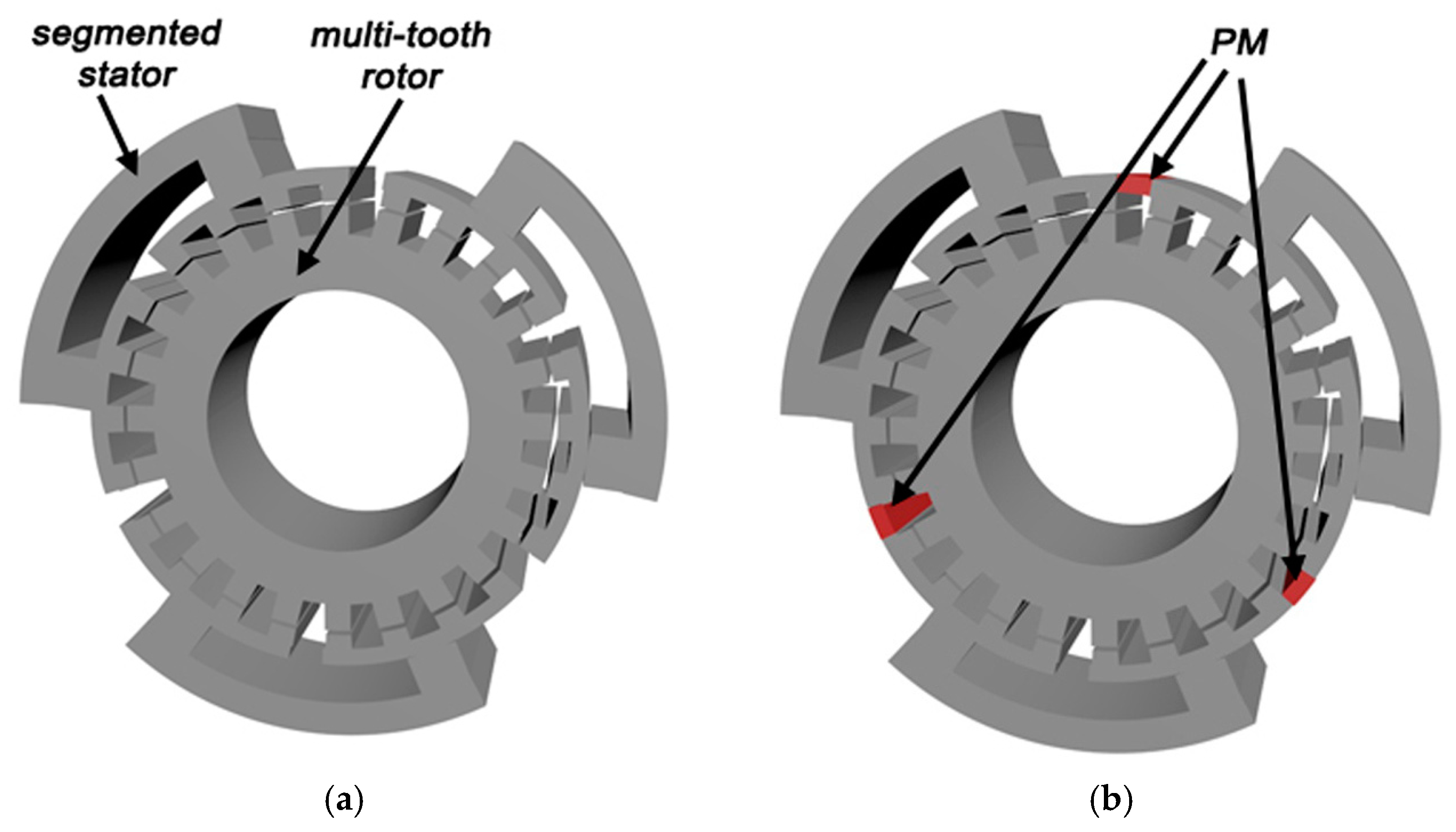
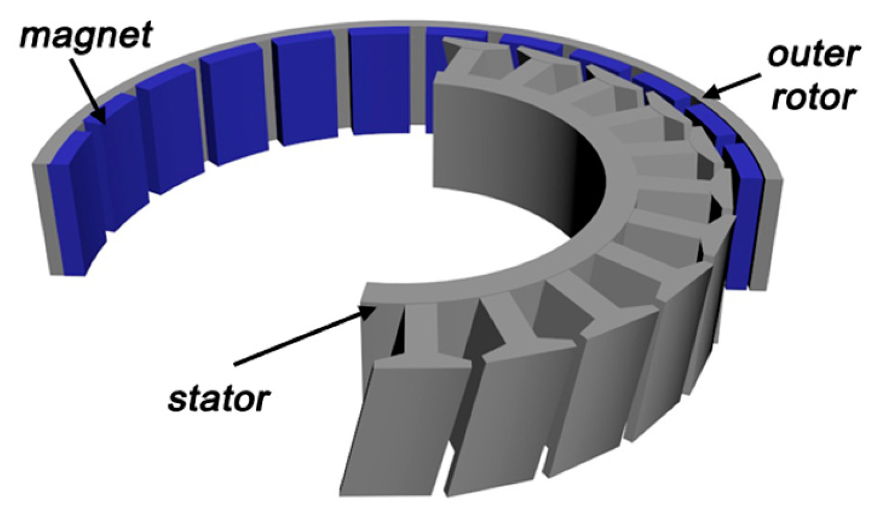
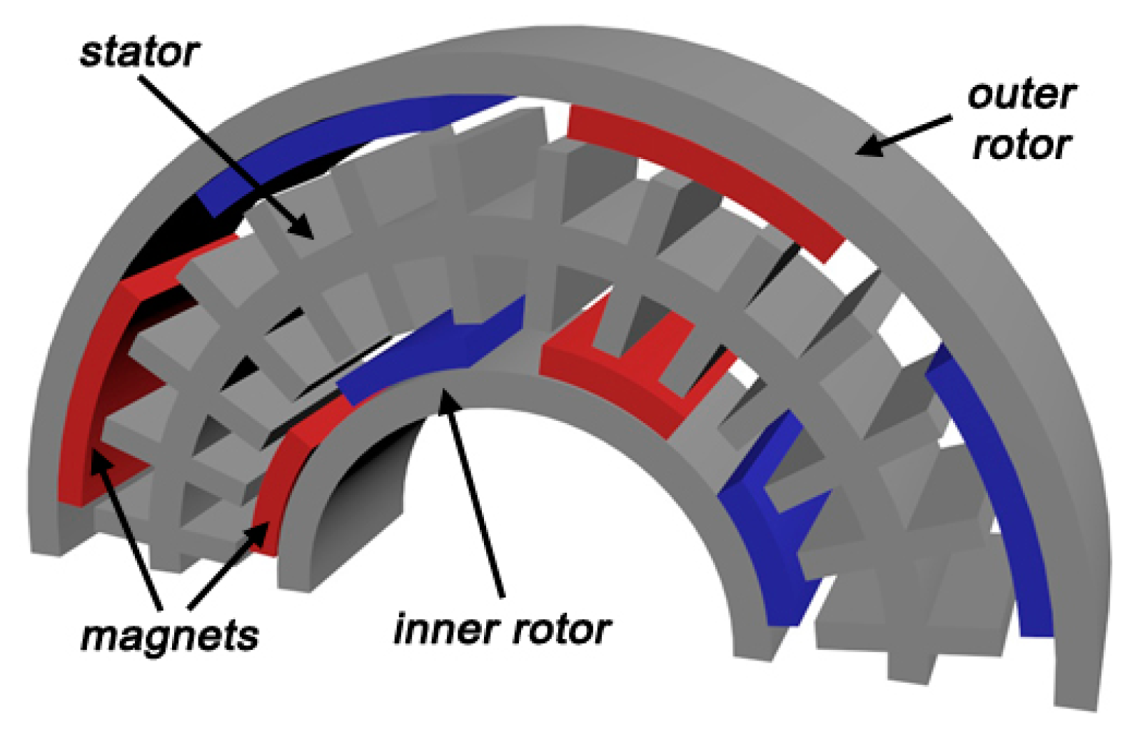
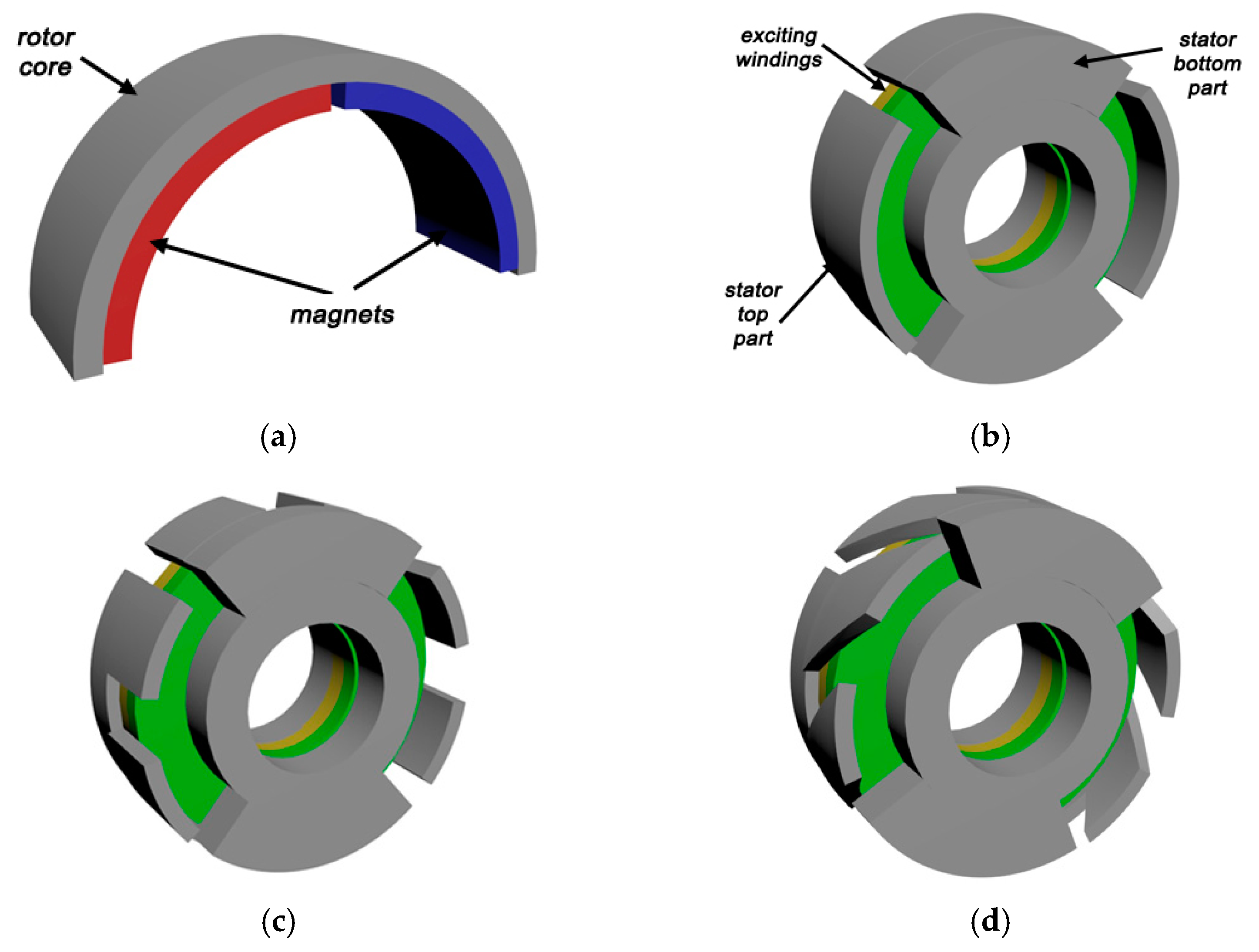
3.3. Switched Reluctance Motors

It is known that reluctance machines generate torque by utilizing the variable reluctance of the rotor. Depending on the stator topology and control system, they are classified as synchronous reluctance machines (SynRM) or switched reluctance machines (SRM). The SRM stator is salient and wound with concentrated coils around each pole, while the SynRM stator typically has a distributed winding. The rotor usually does not have windings, although there are commercial solutions that include a starting cage. The advantages of reluctance motors include durability, relatively high efficiency, low torque ripple, low production costs, and, above all, no permanent magnets in the rotor.
The search for an SRM topology that offers the highest torque density, similar to other motor types discussed, remains a significant challenge. For instance, research utilizing the metaheuristic Gray Wolf Optimization algorithm to optimize the geometric dimensions of the motor has been conducted [115]. In this study, the authors explored various SRM topologies and optimized the dimensions of the stator and rotor poles. The examined topology is depicted in Figure 12. In the initial phase of the study, conventional SRMs with 6/4, 8/6, and 12/8 topologies were compared, revealing that their rated torque, torque density, and efficiency differed by only 2–4%. In the subsequent phase of the research, the 12/8 SRM was optimized. By maintaining the same outer volume, the rated torque increased by 120%, the torque density increased by 170%, and the efficiency improved by 2% compared to a conventional 12/8 switched reluctance motor.
Another team studied the same type of motor, the 12/8 SRM, but focused on the winding arrangement rather than the geometric dimensions of the motor [116]. The aim of the research was to find a winding arrangement that could provide the highest average torque, the lowest torque ripple, reduce core losses (by reducing flux reversal), and maximize motor efficiency. Two winding arrangements were examined: three short-pitch winding variants for single-phase excitation and two full-pitch winding variants for two-phase excitation. In the short-pitched winding, each coil was wound around a single stator pole, while in the fully pitched winding, each coil spanned the surrounding three adjacent stator poles. Research and calculations have shown that, depending on the winding arrangement, the average torque can vary ten-fold and the torque ripple can vary by a factor of fifteen. The highest average torque was achieved by one of the fully pitched winding variants, while one of the short-pitched winding variants allowed for minimizing total losses while achieving 85% efficiency across a wide speed range.
Outer-rotor SRM topologies are of interest when the motor is mounted in the wheel of an electric vehicle. Research on three topologies of this type of motor was described in [117]. All motor topologies were designed to generate the same torque of 18 Nm at a specified speed of 600 rpm. The following topologies of switched reluctance motors were tested: 12/26, 6/10, and 12/8, as shown in Figure 13. During the tests, it was assumed that the external diameter of the motors would not vary and that the maximum current density in the windings would remain constant. Moreover, the stator package would have a maximum length of 40 mm and an air gap thickness of 0.4 mm. The initially proposed topology (12/26 SRM) had an innovatively designed rotor, while the core was built in two variants with different lamination materials. The research conducted showed that the best motor efficiency (88%) was achieved by the 12/26 SRM with a core made of M27-29G material. The same motor with unchanged dimensions and a core made of M19-24G material achieved 4% less efficiency. The torque ripple of the motor with a package made of M27-29G material was more than twice that of the motor with a core package made of M19-24G material. Torque density was also 25 percent lower. At the same time, the 12/26 SRM with a core made of M19-24G material had significantly lower torque ripple and a 20% higher torque density than the other two solutions, 6/10 and 12/8 SRM.
A similar line of research was conducted by a team investigating the hybrid excitation of a switched reluctance motor (HESRM). This research aimed to increase average torque and decrease torque ripple without altering the motor topology or using permanent magnets [118]. In known HESRM designs, additional permanent magnets are used to achieve the intended goal. In this case, the study was carried out on a 12/8 field 3-phase SRM with hybrid excitation. To achieve the goal, the main and auxiliary poles of the stator were separated—see Figure 14. It should be noted that in the recommended motor, both main and auxiliary windings generate effective flux. Based on the test results, the prototype motor was compared to a conventional SRM with the same geometric dimensions. The comparisons showed a several-fold increase in the average torque generated by HESRM over a wide range of excitation currents. This difference also persisted over a wide speed range (from 1200 to 3600 rpm). Additionally, the torque ripple was reduced by nearly three times compared to a conventional motor.
The challenges of implementing hybrid excitation in a segmented stator-switched reluctance motor (SRM) with permanent magnets were discussed in [119]. In this research, experiments were performed on a 12/10-pole PM HESRM with a segmented stator and a 12/10-pole conventional SRM. Both motors had identical geometric dimensions. The segmented stator structure proposed is illustrated in Figure 15. The stator of the segmented HESRM was composed of six separate U-shaped segments, with an NdFeB permanent magnet placed between two poles in each stator segment. For the tested motors, the difference in static torque varied from 4% to 40%, depending on the excitation current. The torque ripple for the PM HESRM was found to be 20–40% smaller than that of the conventional SRM. The proposed design is characterized by higher torque density (in the same range of up to 20–40%) and efficiency increased by 4–10%. It should be noted that all mentioned parameters depend on the control algorithm (current chopping control or angle position control) and speed. Further detailed investigations of the same motor were conducted and reported in [120]. Their goal was to analyze how the width of permanent magnets affects average torque and how the rotor pole-arc coefficient influences both average torque and torque ripple. Studies have shown that increasing the thickness of permanent magnets in the range from 2.5 to 8.5 mm led to an approximately 20% increase in the average torque (for a given current). In turn, increasing the rotor pole-arc coefficient resulted in a 44% decrease in average torque and a 12% reduction in ripple torque. A study on the effect of permanent magnets (PMs) placed between the stator teeth on a two-phase 16/18-pole SRM was discussed in [121]. The study compared two motors with the same topology, one with permanent magnets and the other without. It was demonstrated that the presence of PMs significantly reduced cogging torque. Depending on the phase current, the average torque increased by 250%, while the ripple torque remained relatively constant. Further modifications to the rotor design and detailed research on the 12/4 PM-HESRM were presented in [122]. The research team proposed a new topology of a segmented rotor with only four poles. The operational parameters of this proposed structure were compared to those of the 12/10 PM-HESRM and detailed in [119]. Both configurations had similar geometric specifications, except for the stator pole arc, which was 16 degrees for the 12/4 structure and 15 degrees for the 12/10 structure. The proposed design incorporated both ferromagnetic and nonmagnetic materials in the rotor—see Figure 15c. As a result of the research, it was found that the 12/10 motor generated higher average torque at low speeds, while the new proposed design generated higher average torque at high speeds. For instance, at 500 rpm (at 120 V), the torque values were 5 Nm and 3.8 Nm, respectively. At 1500 rpm (at 150 V), it was 1.67 Nm and 4.25 Nm, and at 2000 rpm (at 150 V), the values were 0.96 Nm and 2.55 Nm. Both designs had relatively low cogging torque (less than 1% of average torque), but the new solution had 3–4 times lower cogging torque compared to the 12/10 PM-HESRM.
The concept of creating auxiliary stator poles is not limited to solutions using hybrid excitation, as seen in the HESRM topology. An example of such a solution for a segmented rotor SRM can be found in [123]. The SSRM solution combines the main poles (excited by current in windings) with auxiliary stator poles. The main poles have exciting windings, while the auxiliary poles serve as flux return pathways without exciting windings. The rotor consists of several separate segments, each embedded in a non-magnetic isolator, as shown in Figure 16. The tested motor was optimized by applying various geometric constraints. Compared to the initial design, the average torque increased by 40%, and the torque ripple was reduced by 66%. It is worth noting that the torque ripple in the initial design was 94% of the average torque, whereas in the optimized design it was only 32%. After optimization, the motor efficiency remained relatively stable at around 90%.
A different line of research is described in [124]. Conventional SRM motors are known to have a relatively high torque ripple. Therefore, the authors focused on finding a motor topology that significantly reduces torque ripple compared to conventional designs. As a result, they proposed the use of a six-phase SRM with a misaligned rotor segment and two phases operating simultaneously—see Figure 17. It is known that torque ripple decreases as the number of rotor poles increases. Despite this, the authors suggested reducing the number of rotor poles. They conducted a study and evaluated the proposed 12/4 6-phase SRM and compared it with the conventional 12/8 3-phase SRM approach. It was assumed that the stator outer diameter, stack length, and air gap thickness of both motors would be the same during testing. A notable benefit of the suggested motor topology is a 45% reduction in torque ripple (at 1500 rpm). However, at 3000 rpm, this reduction is practically imperceptible. Another significant benefit is a 3.5-fold increase in the average static torque generated for a given current. The drawback of the longer length of the copper winding in the recommended topology is that it reduces the motor’s efficiency. Unfortunately, the authors did not provide the exact amount by which efficiency decreased. In another investigation, an identical 12/4 segmental rotor SRM was compared with a 12/10 conventional SRM and a 12/10 segmental rotor SRM [125]. These motors shared identical design and operating features, including six phases, the outer diameter of the stator and rotor, stack length, and rated current. The research found that the 12/4 segmental rotor SRM had the highest average torque for a given current. Additionally, the average torque in the 12/10 conventional SRM was 14% lower, while in the 12/10 segmental rotor SRM, it was 22% lower. The corresponding normalized torque ripples were 7.4%, 9.4%, and 13.9%, respectively.
Previous descriptions of SRM topologies that can increase average torque and reduce torque ripple did not mention the effect of stator pole shape or stator pole dimensions on these quantities. To address this gap, the research reported in [126] was conducted. The study focused on the 24/16 SRM and compared its operating parameters with the traction motor used in the 2010 Prius drive system. Geometric limitations were determined by the stator outer diameter and rotor axial length of the Prius traction motor. The 24/16 switched reluctance motor underwent multi-criteria optimization, where the stator pole height, stator taper angle, and rotor pole arc angle were optimized within appropriate ranges. The study revealed that increasing the stator pole height from 24 to 27 mm resulted in a 5% reduction in average torque, while the normalized torque ripple showed no decreasing trend. It was found that changing the stator taper angle from 0 to 7 mechanical degrees increased the average torque by 17% and reduced the normalized torque ripple by 30%. However, there was not much difference in the average torque and normalized torque ripple when the rotor pole arc angle was changed from 7 to 7.5 mechanical degrees. Five stator pole shoe shapes were tested but did not lead to significant improvements in the average torque or normalized torque ripple. Nevertheless, the efficiency of the motor under examination was found to be comparable to the efficiency of the traction motor used in the Prius.
Although the original concept of switched reluctance motors did not involve the use of permanent magnets, there are examples of studies on permanent magnet switched reluctance motors (PM-SRMs) in the literature [127]. In this study, the motor topology used includes a rectangular non-rare earth magnet of the Alnico type buried in the stator yoke—see Figure 18a. Despite the use of an unusual 6/4 PM-SRM design, the study showed a significant improvement in operational metrics. Compared to the 6/4 SRM without an Alnico magnet, the average torque (for the specified current) increased by more than 60%, the normalized ripple torque remained relatively constant, and the efficiency increased by 5–7% depending on the speed. The authors of [128] provide more detailed research results on the influence of the size of SmCo permanent magnets inserted in the stator of the two-phase 8/10 PM-SRM. During the tests, the thickness of the magnets was changed in the range of 1–5 mm, and the research results were compared to those obtained for a conventional 8/10 SRM (without permanent magnets) with the same geometric dimensions. The proposed design resulted in a 46% increase in average torque and a 6–7% improvement in efficiency. It was observed that cogging torque accounts for several percent of the average torque and varies significantly with increasing PM thickness, eventually approaching zero for a thickness of 1 mm. Another research team conducted a more detailed analysis of the same type of motor [129], expanding the scope to investigate the impact of both the width and thickness of permanent magnets. During the tests, the PM width ranged from 1 to 5 mm, and the thickness varied from 1 to 10 mm. The results confirmed the findings presented in [128]. Another approach involving PMs placed in the rotor teeth was discussed in [130]. The 12/10 external rotor SRM with both main poles and auxiliary poles in the stator was analyzed. The motor core was composed of six different ferromagnetic materials with different magnetization curves and specific material losses. The study revealed that the choice of material affects the average torque generated (within 10%) but not the ripple torque. The next phase of the research focused on examining how the orientation of the magnets installed in the main poles influenced the motor’s performance. Permanent magnets (PMs) were tested in both horizontal and vertical positions relative to the main pole axis. It was shown that the motor with the PM placed vertically generated 10% more average torque compared to the alternative PM orientation, exhibited 35% less torque ripple, and had more than twice as less cogging torque.
Another team of researchers proposed a modular stator hybrid-excitation switched reluctance motor (MS-HESRM) topology that integrates permanent magnets (SmCo24) into the stator yoke to increase torque density [131]. The stator modules have a unique π-shape, with PMs placed between them (see Figure 18b). The direction of magnetization of the permanent magnets coincided with the magnetic field of the excitation coils. In the tested topology, the stator poles can take two different shapes. An excitation winding was wound around the main pole, while the auxiliary pole (without excitation winding) provided a short flux path. The rotor consisted of 14 poles with a classic shape. The researchers predicted that selecting an appropriate pole arc for the auxiliary pole would lead to a significant reduction in cogging torque. During testing, the sizes of the permanent magnets and arcs were optimized for both the main and auxiliary poles. The research revealed that the thickness of the permanent magnets had little effect on average torque but had a significant impact on cogging torque. Cogging torque decreased as the thickness of the permanent magnet decreased, although it remained minimal at all thicknesses. On the other hand, the width of the permanent magnets had a significantly larger impact on average torque. Increasing the width of the permanent magnets resulted in a corresponding increase in average torque by up to 50% for a given excitation current. It was noted that the effect of permanent magnet width on the cogging torque was less pronounced but still noticeable. The authors also noted that adjusting the arc of the auxiliary pole can increase the cogging torque amplitude by up to five times, highlighting the importance of selecting the appropriate pole arc. A comparison of operational characteristics between the proposed design and a conventional 12/14 SRM showed that the MS-HESRM generated 2.5 times higher average torque. However, the disadvantage of the proposed design was a 15% increase in torque ripple.
According to research conducted by various scholars, skewed rotor poles have been found to help reduce torque ripple. In practical applications, a skewed rotor is achieved by introducing multiple rotor layers that are shifted by a specific angle, as illustrated in Figure 19. This configuration, known as a multi-layer SRM, consists of a stator divided into layers that are not rotated relative to each other. Additionally, each stator layer has its own excitation windings positioned at the poles. A comparative analysis of several multi-layer SRM topologies can be found in [132]. The study investigated both the conventional multi-layer 8/6 SRM (where similar phases in different stator layers are excited simultaneously) and the proposed design of a multi-layer 8/6 SRM (where similar phases in different stator layers are excited by a phase-shifted current). The tests compared the operational parameters of the motors, increasing the number of layers from two to five and the displacement angle (in the proposed solution) from two to ten degrees. In a conventional motor, the displacement angle remained constant. The proposed design showed a significant reduction in torque ripple depending on the number of layers and displacement angle. In the conventional design, the torque ripple reached a value of 95% of the average torque, while in the proposed design it was reduced to 4.4% without reducing the average torque. It was also found that for each number of layers, there is a specific displacement angle for which the torque ripple is the smallest. For example, for five layers, the angle is 3 degrees; for four layers, it is 3.75 degrees; for three layers, it is 5 degrees; and for two layers, it is 7.5 degrees. A similar technique was used to improve the operating characteristics of a 12/8 switched reluctance motor. The conventional and recommended designs were compared using the same assumptions as for the 8/6 SRM. In this scenario, with the five-layer structure, the torque ripple was reduced from 127% (conventional design) to 6.2% (proposed topology) without affecting the average torque.
In the case of the SRM, research on the effect of non-uniform air gap thickness on torque ripple is not widely reported in the literature. However, there are examples in the literature indicating that torque ripple can be reduced using this technique [133,134]. The work [133] describes research on a 12/8 SRM. The authors proposed the use of a mirror structure to create a non-uniform air gap. The effectiveness of two solutions was tested: the first one, in which the M-type design has a cutout section on the right side of the pole, and the N-type design on the left side; and the second one in which one or two holes were drilled—see Figure 20. The first design solution reduced the average torque by 1.5% (for a given excitation current), and the second one (with one hole) reduced it by 2.2%. By changing the bevel shape (first design) and the size and position of the hole (second design), the torque ripple was reduced from 68.8% (conventional design) to 61.8% (two-hole design). Then, testing the same type of motor by manipulating the shape of the rotor poles, the authors managed to reduce the torque ripple from 69% to 39% and the average torque by only 3% [134].
An interesting research direction regarding the construction of a double-stator is discussed in many papers [135,136,137]. For instance, in [135] the operation of a switched reluctance machine with a segmented double-stator (16/18/16 SDS-SRM) was investigated and illustrated—see the SDS-SRM topology in Figure 21. The authors’ main task was to select appropriate sequences of winding excitation for the external and internal poles of the stator. Throughout the study, the authors identified four current excitation sequences, one of which showed promise. Using this sequence, the motor underwent a more detailed analysis. The motor’s operating parameters were evaluated both when energizing the windings of individual stators and when simultaneously energizing the windings of both stators. The authors compared the average torque and torque ripple in the mentioned scenarios at a specific speed. The conducted tests revealed that the average torque when energizing the external stator windings was 6.15 Nm, with a ripple torque of 112%. However, when energizing the internal stator windings, the values were 5.12 Nm and 112%, respectively. When both stator windings were energized, the values were 11.2 Nm and 54%, respectively. In comparison, for a conventional DS-SRM, when both stator windings were excited, the values were 10.5 Nm and 115%, respectively.
There are descriptions in the literature of switched reluctance motors that use permanent magnets to generate higher average torque while minimizing cogging torque. Based on these works, it is clear that further research is needed to recommend new topologies with reduced magnet volume. One such innovative topology is presented in [138], where the authors propose a 48/50-tooth exterior-rotor PM-SRM with the PMs embedded between specific stator poles, as shown in Figure 22a. The test results of this innovative motor were compared to the same design without PM and a conventional 12/10 SRM design. Calculations have shown that the proposed PM-SRM topology has a negligible cogging torque (tenths of a percent of average torque). Additionally, the PM-SRM generated up to 100% higher average torque compared to the conventional 12/10 SRM for given excitation currents. On the other hand, the proposed topology without PMs also generated 15–60% higher average torque than the 12/10 SRM, depending on the excitation current value. Another topology showing a double-rotor permanent magnet SRM (DR-PMSRM) using the same technique of embedding magnets between stator teeth is described in [139]. This design included permanent magnets in both portions of the stator due to the presence of two rotors. The proposed DR-PMSRM combined two SRMs: 12/10 and 24/20, as shown in Figure 22b. In order to compare operational characteristics, a conventional DR-SRM with identical construction dimensions was also constructed. Various combinations of the number of teeth per stator pole were selected to determine the optimal number of stator and rotor teeth. The research findings indicated that the proposed DR-PMSRM design can generate up to 60% higher average torque compared to the DR-SRM, depending on the excitation current value. While the suggested DR-PMSRM topology design had minimal cogging torque, the inner and outer rotors generated different cogging torques. The inner rotor generated virtually zero cogging torque, whereas the cogging torque generated by the outer rotor was several times higher but still negligible. The authors reported that at 1000 rpm, the inner rotor of the DR-PMSRM generated 50% higher average torque and 100% lower torque ripple compared to the DR-SRM. The outer rotor of the DR-PMSRM had a 25% higher average torque and a 50% lower ripple torque, respectively.
The concept of creating multi-tooth SRMs was modified and described in [140]. Two structures were tested during the research. The first topology was a 3-phase 24/25-tooth MT-SRM where the flux sources are two concentrated windings located at the stator poles. The second topology was a 3-phase 24/25-tooth MT-HESRM with PMs embedded between adjacent stator teeth belonging to different excitation phases—see Figure 23. In both topologies, the stator was composed of three separate C-shaped modules with concentrated windings. The advantage of the proposed MT-HESRM was that it generated approximately zero cogging torque because the PM flux at zero excitation current did not tend to cross the air gaps. According to the authors, depending on the speed, the proposed MT-HESRM generated 60–80% higher average torque while maintaining the same torque ripple (120% average torque).
Table 5 summarizes the effectiveness of the described design ideas in improving the operating characteristics of switched reluctance motors for LEVs.

3.4. BLDC Motors

BLDC motors, thanks to their simple topology, provide high starting torque, low noise, and long operating time, achieving efficiency of up to 95% [141]. These types of motors are designed to be mounted inside the rim of a lightweight electric vehicle and are often compared to other designs such as axial flux motors (AFM). An interesting comparison can be found in [142], where the authors compared these two types of motors with the same torque-to-volume ratio. The outer diameters and axial lengths of the motors were clearly different, but they had the same volume. The study used commercial motors with comparable rated torque, efficiency of 91.46% (AFM) and 88.44% (BLDC hub), and total net weights of 22.5 kg (AFM) and 5.2 kg (BLDC hub). As a result of the optimization of both motors, the efficiency increased to 94.9% and 90.35%, respectively. The comparison showed that the AFM achieved higher efficiency, but the torque-to-weight ratio was much more favorable (four times difference) for the BLDC motor. It is known that the use of permanent magnets results in a trapezoidal flux density distribution in the air gap. Combined with the non-sinusoidal current, this is one of the causes of torque ripple. Many researchers are focusing on reducing torque ripple by using techniques such as skewing, using short pitch winding, placing wedges in slot openings, and determining the shape and dimensions of magnet poles. Choosing the appropriate control strategy is a separate aspect leading to torque ripple reduction that is not addressed in this paper. A detailed discussion and comparison of different control strategies for BLDC motors can be found in [143].
As demonstrated in [144], the reduction in cogging torque can be effectively achieved by selecting the magnet material in combination with the magnet thickness and the magnet arc. The tests were conducted on a BLDC motor with 27 slots and 4 poles, featuring a nominal torque of 3 Nm and a rated speed of 1500 rpm. Keeping the motor’s geometric dimensions constant, four types of permanent magnets were used, with their geometric dimensions selected to maintain the motor’s average torque at 3 Nm +/− 15%. The permanent magnets used in the study were Alnico, SmCo, NdFeB, and a ceramic composed of strontium carbonate and iron oxide. The authors determined that the most appropriate dimensions of the magnet are Alnico—13 mm (thickness) and 80 degrees (magnet arc); SmCo—6.35 mm and 66 degrees; NdFeB—2.56 mm and 60 degrees; and ceramic—2.5 mm and 74 degrees, respectively. The tested motors maintained a constant average torque at speeds up to 2600 rpm. In this range, the motor with NdFeB magnets generated an average torque of 3 Nm, while the motor with ceramic magnets generated only 2.55 Nm. Motors equipped with SmCo and NdFeB magnets generated the highest cogging torque, accounting for 36% of the average torque. The motor with Alnico magnets generated a significantly lower cogging torque of only 5%, and the motor with ceramic magnets generated the lowest cogging torque of 1.5%.
The authors, in search of the optimal shape and dimensions of stator slots, introduced a new direction of research on BLDC motors [145]. They tested a BLDC motor with 24 stator slots and four rotor poles composed of permanent magnets. Four different types of stator slots were used in the tests, with sizes chosen to maintain the same average output torque while keeping the slot area constant. The adjusted slot dimensions resulted in varying maximum flux densities in the stator yoke (ranging from 1.33 to 1.52 T) and stator teeth (ranging from 1.56 to 1.74 T). The authors observed torque ripple fluctuations between 45% and 55% of the average torque. A similar research approach to the selection of stator slot sizes was discussed in [146]. The study focused on a three-phase outer-rotor BLDC motor designed for a 10.5-inch rim. The authors aimed to find the optimal relationship between poles and slots, winding turns, and stator tooth width to achieve the maximum back EMF value. Starting with a commercial solution with 27 stator slots and 30 rotor poles, the research identified the motor’s optimal design specifications: 32 rotor poles, 36 stator slots, 20 winding turns (initially 14 turns), and a stator tooth width of 6.12 mm (initially 4.75 mm). This led to a nearly two-fold increase in the EMF(RMS) value and a several percent improvement in efficiency.
Another research team conducted an in-depth study on an outer-rotor BLDC motor with a higher power rating than reported in [146]. The results of their extensive research can be found in [147]. The main goal of the research was to reduce cogging torque while considering the skew of the stator slots. In the first phase of the research, the focus was on a non-skewed motor. Next, the correlation between cogging torque and the length of the magnetic core was determined by changing the core length from 40 to 60 mm. As expected, lengthening the cores resulted in higher cogging torque, with an increase of 66% greater than the ratio of the selected core lengths. In the second phase of the research, a motor with a 50 mm long core was used, in which the skew angle of the stator slots varied from 0 to 1 electrical degree—see Figure 24. The greatest reduction in cogging torque, reaching 98%, was achieved with a slot skew of 1 electrical degree. This topology resulted in a torque ripple of 30%. It is important to note that the use of a skewed topology impacted both the operating characteristics and the speed at which maximum efficiency was reached. However, the maximum efficiency did not change significantly. It is known that the change in average torque due to the skew of the stator slots is speed dependent. At low speeds, the non-skewed motor generated the highest average torque, which was 40% greater than that of the motor with a 1-degree skew. For half the rated speed, the effect of the slot skew on the generated torque was negligible. For speeds higher than the rated speed, the torque generated by the 1-degree skewed motor dominated.
The selection of appropriate slot–pole combinations is an effective method of reducing cogging torque in BLDC motors. The results of work carried out in this area are presented in detail in [148]. The authors described the optimization process of a conventional BLDC motor with an external rotor, which was used in self-balancing electric vehicles. According to the authors, for BLDC motors operating at low speeds and high loads, a high winding ratio and flux linkage can reduce winding losses and improve efficiency. The highest flux linkage can be achieved when the ratio of the tooth tip width to the pole width is 1. However, designers can set a fixed ratio of slot opening to slot pitch. As a result, the ratio of tooth tip width to pole width depends on the slot-pole combination utilized. Therefore, the authors recommend carefully selecting the slot-pole combination that minimizes cogging torque and torque ripple. Test results showed that the cogging torque of the conventional BLDC motor tested was 2.3%. The authors demonstrated that selecting a better slot–pole combination for a conventional 27/30 BLDC motor can improve performance. By choosing the new 30/32 combination, the cogging torque of the tested motor was ten times lower compared to the 27/30 combination. The same line of research was conducted for a 2.5 kW motor [149]. It was assumed that the output power value remained constant throughout the test cycle. Five slot/pole combinations were tested to determine the operating characteristics of the motors. According to the authors, the following combinations were considered suitable for an in-wheel BLDC motor: 24/18, 24/20, 36/24, and 36/30. Studies indicated that changing the slot/pole combination under given constraints increased the rated torque by 26% and motor efficiency by 2%. In the subsequent testing phase, the 24/20 slot/pole combination was selected due to the highest motor efficiency. The stator tooth width, slot opening, slot height, and slot width were assumed to remain constant during the simulations for three different stator slot shapes. The tests revealed that the rated torque changed by 8%, while the efficiency remained almost unchanged.
A similar study was conducted by another team of researchers focusing on investigating the impact of slot/pole combinations on the average torque and cogging torque of a spoke-type BLDC motor [150]. Searching for the optimal design, they proposed changing the number of poles from four to ten and the number of stator slots from six to thirty. The study included an analysis of motor operating characteristics, vibration analysis, and thermal analysis of motors with various slot/pole combinations. Test results indicated that the optimal slot/pole combination for a spoke-type BLDC motor is 12/4. However, selecting different slot/pole combinations resulted in a tenfold difference in average torque. Similar fluctuations were observed in cogging torque values.
Optimizing the geometric dimensions of individual parts of the magnetic circuit can improve the operating characteristics of a specific type of BLDC motor. An example of such optimization applies directly to an 8-pole inner rotor BLDC motor with an output power of 670 W and a rated torque of 5.7 Nm [151]. Throughout the optimization process, certain dimensions remained constant: rotor diameter, axial length, stator outer diameter, slot height, and air gap length. It was demonstrated that by increasing the magnet thickness from 4 to 6 mm, the rated torque increased by 3% while reducing the cogging torque by 22%. In turn, adjusting the skew of the stator slots from 0 to 0.95 of the stator pitch resulted in a 2% reduction in the rated torque and a 20-fold reduction in cogging torque. The impact of the distance between the rotor poles was also examined, showing that the rated torque remained almost constant, while the cogging torque varied within 200% without a clear trend of change. This action resulted in an increase in motor efficiency, reaching 91%. The team that published the research results in [152] conducted research in a similar direction. The team focused on investigating the influence of the arc pole in the rotor on the rated torque and efficiency of a BLDC motor with 18 semi-closed stator slots and a 6-pole surface-mounted permanent magnet configuration. The stator topology remained constant throughout the experiments. Two rotor structures were examined, with the only modification being the spacing between the magnets on the rotor surface. In the first case, each of the three stator slots covered one magnet on the rotor surface, while in the second case, each surface-mounted magnet on the rotor covered one stator slot. The first motor topology was characterized by 30% lower rated torque and 8% higher efficiency compared to the second topology.
Spoke-type BLDC motors have significantly lower cogging torque compared to other types of permanent magnet motors, such as Interior Permanent Magnet motors. This leads to the examination of various design considerations for spoke-type BLDC motors. For example, test results of a spoke-type BLDC motor with 1.21 mm thick magnets mounted on the rotor surface are presented in [153]. The study examined poles composed of one, two, three, and four magnets while maintaining the remaining design parameters of the motor constant. Average torque and torque ripple were calculated for each pole configuration. It was found that the highest average torque of 13 Nm was achieved for poles consisting of two magnets. For the same topology, the lowest torque ripple of 0.28 Nm was obtained. In other cases, the average torque was 3–4% lower, and the ripple torque was even 0.3 Nm higher. In the next steps, the same type of motor was tested with a power supply from three, five, and seven phases [154]. The aim of the research was to demonstrate that increasing the number of phases reduces torque ripples. To achieve this goal, the number of stator slots, outer diameter, and slot geometry were changed, while the rotor geometry and diameters remained unchanged. The number of poles in the tested motor was 24 (which was independent of the number of phases), and the number of slots was 27 (for 3 phases), 55 (for 5 phases), and 63 (for 7 phases). Tests showed a reduction in torque ripple from 10% (3 phases) to 5–6% (5 and 7 phases).
The concept of a multi-phase power supply to reduce cogging torque and torque ripple was applied in the research of a dual-rotor BLDC motor [155]. The authors worked on a motor with the topology shown in Figure 25. Three power supply variants were selected: three-phase, five-phase, and seven-phase. During the tests, most of the geometric dimensions remained unchanged, and the number of poles remained the same, except for the number of stator slots. The investigation found that the amplitude of the cogging torque decreased as the number of phases increased. For a 3-phase power supply, this value was 0.3 Nm; for a 5-phase power supply it was 0.16 Nm, whereas for a 7-phase power supply, it was only 0.1 Nm. Similarly, the torque ripple amplitude decreased, from 5 Nm for three phases to 2 Nm for seven phases.
An interesting research direction is discussed in [156]. This study investigated the effect of the ratio of a motor’s axial length to its pole pitch (denoted as L/tal) on the operating characteristics of an outer-rotor BLDC motor. The motor under study had 24 stator slots and four poles made of XG196/96 material, mounted on the rotor surface. Initially, the motor had an L/tal ratio of 1. In the first phase of the study, corrections were made to the outer diameter and axial length of the stator, obtaining an axial-length to pole-pitch ratio of 0.75. Subsequently, the motors were tested for various L/tal ratios, ranging up to three, to determine the optimal external stator diameter and length. The pole arc-to-pole pitch ratio was kept constant at each stage. The results indicated that with an increase in L/tal, the average torque increased by 40%, the torque-to-weight ratio decreased by 50%, and the cogging torque increased by 60%.
A completely different direction of research compared to those described above was presented in [157]. The authors tested the outer-rotor BLDC claw-pole motor with the topology shown in Figure 26. The outer rotor had four poles mounted on the rotor surface. The stator of this motor was divided into two parts: the upper stator part and the lower stator part. The authors examined three stator variants: an initial design (#1), a design with inserted auxiliary slots (#2), and a design with auxiliary slots and a stator claw skewing of 45 degrees (#3). Simulations showed that the amplitude of the cogging torque varies depending on the selected variant. Variant #3 had three times lower cogging torque amplitude than variants #1 and #2. Variant #3 also turned out to be the best solution, reducing the torque ripple amplitude by approximately 20% compared to variant #1.
Table 6 summarizes the effectiveness of the described design ideas in improving the operating characteristics of BLDC motors designed for LEVs.

4. Discussion and Conclusions

Improving the operational characteristics of light electric vehicles, exploring new areas of application, and meeting the growing expectations of users pose new challenges for designers. Users expect the availability of next-generation electric motors with improved efficiency and torque density. The new design solutions are expected to enhance driving comfort and reduce motor noise. To meet users’ expectations, designers implement design improvements and sophisticated control algorithms. This review focuses exclusively on motor topology modifications that result in increased motor efficiency, reduced torque ripple, and higher average torque. In the case of motors with permanent magnets, the impact of the proposed modifications on the cogging torque is also taken into account. Importantly, these modifications are introduced while maintaining the same motor volume, often with reduced use of materials such as permanent magnets. This review primarily focuses on describing the design changes introduced to four groups of motors used in LEVs, which are commonly mounted inside the drive wheel rims. As shown, the proposed design changes aiming to increase torque density often require the use of permanent magnets, although this is not necessary for some motor types. Interesting examples in this respect are the design solutions of dual-rotor motors. Regardless of the motor type, cogging torque is primarily reduced by shaping the heads of the stator teeth or rotor magnets. In turn, torque ripples are generally limited by using a combination of core material, slot/pole magnet combinations, and rotor magnet shape selection. The increase in average torque is achieved by selecting the shape of the stator teeth or rotor permanent magnets and by selecting slot/pole combinations. As mentioned, these motor design modifications were discussed for four motor groups. The results presented in the tables at the end of the description of each group inform the reader about the effectiveness of a given modification. Some topology modifications improve motor operating characteristics marginally (by a few to a dozen percent), while others change them significantly, even several times. These conclusions also apply to the motor topologies changed by researchers, which led to improved operational characteristics of commercial motors. It should be noted that this problem has been the subject of research by many teams and publications. This review mainly focuses on the latest research resulting from the availability of new construction materials, the wide availability of modern software tools, and the presence of new design challenges.

Funding

This research received no external funding.

Conflicts of Interest

The author declares no conflicts of interest.

References

  1. Electric Cars: A Revisit from History. Available online: https://chargetrip.com/blog/electric-cars-a-revisit-from-history (accessed on 1 March 2024).
  2. Hill, G.; Heidrich, O.; Creutzig, F.; Blythe, P. The Role of Electric Vehicles in Near-term Mitigation Pathways and Achieving the UK’s Carbon Budget. Appl. Energy 2019, 251, 113111. [Google Scholar] [CrossRef]
  3. Electric Vehicles. Available online: https://www2.deloitte.com/us/en/insights/focus/future-of-mobility/electric-vehicle-trends-2030.html (accessed on 1 March 2024).
  4. Trends in Electric Cars. Available online: https://www.iea.org/reports/global-ev-outlook-2024/trends-in-electric-cars (accessed on 1 March 2024).
  5. EV Motors Boost Copper Demand. Available online: https://internationalcopper.org/wp-content/uploads/2020/03/EV_Motors-Boost-Copper-Demand.pdf (accessed on 1 March 2024).
  6. Lungoci, C.M.; Georgescu, M.; Calin, M.D. Electrical Motor Types for Vehicle Propulsion. In Proceedings of the 13th International Conference on Optimization of Electrical and Electronic Equipment (OPTIM), Brasov, Romania, 24–26 May 2012. [Google Scholar] [CrossRef]
  7. Ramya, K.C.; Ramani, J.G.; Sridevi, A.; Rai, R.S.; Shirley, D.R.A. Analysis of the Different Types of Electric Motors Used in Electric Vehicles. In E-Mobility; Kathiresh, M., Kanagachidambaresan, G.R., Williamson, S.S., Eds.; Springer: Cham, Switzerland, 2022; pp. 43–57. [Google Scholar]
  8. El Hadraoui, H.; Zegrari, M.; Chebak, A.; Laayati, O.; Guennouni, N. A Multi-Criteria Analysis and Trends of Electric Motors for Electric Vehicles. World Electr. Veh. J. 2022, 13, 65. [Google Scholar] [CrossRef]
  9. Cao, Z.; Mahmoudi, A.; Kahourzade, S.; Soong, W.L. An Overview of Electric Motors for Electric Vehicles. In Proceedings of the 31st Australasian Universities Power Engineering Conference (AUPEC), Perth, Australia, 26–30 September 2021. [Google Scholar] [CrossRef]
  10. Sanguesa, J.A.; Torres-Sanz, V.; Garrido, P.; Martinez, F.; Marquez-Barja, J. A Review on Electric Vehicles: Technologies and Challenges. Smart Cities 2021, 4, 372–404. [Google Scholar] [CrossRef]
  11. Bhatt, P.; Mehar, H.; Sahajwani, M. Electrical Motors for Electric Vehicle—A Comparative Study. In Proceedings of the Recent Advances in Interdisciplinary Trends in Engineering & Applications (RAITEA), Indore, India, 14–16 February 2019. [Google Scholar] [CrossRef]
  12. Agamloh, E.; von Jouanne, A.; Yokochi, A. An Overview of Electric Machine Trends in Modern Electric Vehicles. Machines 2020, 8, 20. [Google Scholar] [CrossRef]
  13. Kahourzade, S.; Mahmoudi, A.; Soong, W.L.; Ferrari, S.; Pellegrino, G. Correction of Finite-Element Calculated Efficiency Map using Experimental Measurements. In Proceedings of the IEEE Energy Conversion Congress and Exposition (ECCE), Baltimore, MD, USA, 29 September–3 October 2019. [Google Scholar] [CrossRef]
  14. Kahourzade, S.; Mahmoudi, V.; Soong, W.; Ertugrul, N.; Pellegrino, G. Estimation of PM Machine Efficiency Maps from Limited Data. IEEE Trans. Ind. Appl. 2020, 56, 2612–2621. [Google Scholar] [CrossRef]
  15. Kahourzade, S.; Mahmoudi, A.; Soong, W.L.; Pellegrino, G. A Practical Method for Estimating Efficiency Maps for PM Machines Using a Reduced Number of Tests. In Proceedings of the IEEE Vehicle Power and Propulsion Conference (VPPC), Hanoi, Vietnam, 14–17 October 2019. [Google Scholar] [CrossRef]
  16. Maggetto, G.; Van Mierlo, J. Electric and Electric Hybrid Vehicle Technology: A Survey. In Proceedings of the IEE Seminar Electric, Hybrid and Fuel Cell Vehivles, Durham, UK, 11 April 2000. [Google Scholar] [CrossRef]
  17. Singh, K.V.; Bansal, H.O.; Singh, D. A Comprehensive Review on Hybrid Electric Vehicles: Architectures and Components. J. Mod. Transp. 2019, 27, 77–107. [Google Scholar] [CrossRef]
  18. Xue, X.D.; Cheng, K.W.E.; Cheung, N.C. Selection of Electric Motor Drives for Electric Vehicles. In Proceedings of the Australasian Universities Power Engineering Conference, Sydney, Australia, 14–17 December 2008. [Google Scholar]
  19. Lulhe, A.M.; Date, T.N. A Technology Review Paper for Drives Used in Electrical Vehicle (EV) & Hybrid Electrical Vehicles (HEV). In Proceedings of the 2015 International Conference on Control, Instrumentation, Communication and Computational Technologies (ICCICCT), Kumaracoil, India, 18–19 December 2015. [Google Scholar] [CrossRef]
  20. Rajashekara, K. Present Status and Future Trends in Electric Vehicle Propulsion Technologies. IEEE J. Emerg. Sel. Top. Power Electron. 2013, 1, 3–10. [Google Scholar] [CrossRef]
  21. Jose, C.P.; Meikandasivam, S. A Review on the Trends and Developments in Hybrid Electric Vehicles. In Innovative Design and Development Practices in Aerospace and Automotive Engineering; Bajpai, R.P., Chandrasekhar, U., Eds.; Springer: Singapore, 2017; pp. 211–229. [Google Scholar] [CrossRef]
  22. Wang, J.; Yuan, X.; Kais, A. Design Optimization of a Surface-Mounted Permanent-Magnet Motor with Concentrated Windings for Electric Vehicle Applications. IEEE Trans. Veh. Technol. 2013, 62, 1053–1064. [Google Scholar] [CrossRef]
  23. Credo, A.; Tursini, M.; Villani, M.; Di Lodovico, C.; Orlando, M.; Frattari, F. Axial Flux PM In-Wheel Motor for Electric Vehicles: 3D Multiphysics Analysis. Energies 2021, 14, 2107. [Google Scholar] [CrossRef]
  24. Gao, P.; Gu, Y.; Wang, X. The Design of a Permanent Magnet In-Wheel Motor with Dual-Stator and Dual-Field-Excitation Used in Electric Vehicles. Energies 2018, 11, 424. [Google Scholar] [CrossRef]
  25. Deng, Q.-L.; Xiao, F.; Huang, W.-T. Design of New-type Axial Flux Permanent Magnet in-Wheel Machine. In Proceedings of the International Conference on Electrical and Control Engineering, Wuhan, China, 25–27 June 2010. [Google Scholar] [CrossRef]
  26. Pellegrino, G.; Vagati, A.; Boazzo, B.; Guglielmi, P. Comparison of Induction and PM synchronous Motor Drives for EV Application Including Design Examples. IEEE Trans. Ind. Appl. 2012, 48, 2322–2332. [Google Scholar] [CrossRef]
  27. Qi, H.; Ling, L.; Liwei, Z. Design and Research of Axial Flux Permanent Magnet Motor for Electric Vehicle. In Proceedings of the IEEE 3rd International Electrical and Energy Conference (CIEEC), Beijing, China, 7–9 September 2019. [Google Scholar] [CrossRef]
  28. Güneşer, M.T.; Dalcali, A.; Öztürk, T.; Ocak, C.; Cernat, M. An Induction Motor Design for Urban Use Electric Vehicle. In Proceedings of the IEEE International Power Electronics and Motion Control Conference (PEMC), Varna, Bulgaria, 25–28 September 2016. [Google Scholar] [CrossRef]
  29. Lumyong, P.; Sarikprueck, P. A Study on Induction Motor Efficiency Improvement for Implementing in Electric Vehicle. In Proceedings of the 21st International Conference on Electrical Machines and Systems (ICEMS), Jeju, Republic of Korea, 7–10 October 2018. [Google Scholar] [CrossRef]
  30. Takorabet, N.; Martin, J.P.; Meibody-Tabar, F.; Sharif, F.; Fontaine, P. Design and Optimization of a Permanent Magnet Axial Flux Wheel Motors for Electric Vehicle. In Proceedings of the XXth International Conference on Electrical Machines, Marseille, France, 2–5 September 2012. [Google Scholar] [CrossRef]
  31. Hong, C.; Huang, W.; Hu, Z. Performance Calculation of a Dual Stator Solid Rotor Axial Flux Induction Motor Using the Multi-Slice and Multi-Layer Method. IEEE Trans. Magn. 2019, 55, 8100709. [Google Scholar] [CrossRef]
  32. Mei, J.; Zuo, Y.; Lee, C.H.T.; Kirtley, J.L. Modeling and Optimizing Method for Axial Flux Induction Motor of Electric Vehicles. IEEE Trans. Veh. Technol. 2020, 69, 12822–12831. [Google Scholar] [CrossRef]
  33. Dianati, B.; Kahourzade, S.; Mahmoudi, A. Axial-Flux Induction Motors for Electric Vehicles. In Proceedings of the IEEE Vehicle Power and Propulsion Conference (VPPC), Hanoi, Vietnam, 14–17 October 2019. [Google Scholar] [CrossRef]
  34. Hong, C.; Huang, W.; Hu, Z. Design and analysis of a high-speed dual stator slotted solid rotor axial flux induction motor. IEEE Trans. Transport. Electrific. 2019, 5, 71–79. [Google Scholar] [CrossRef]
  35. Kahourzade, S.; Mahmoudi, A.; Roshandel, E.; Cao, Z. Optimal Design of Axial-Flux Induction Motors Based on an Improved Analytical Model. Energy 2021, 237, 121552. [Google Scholar] [CrossRef]
  36. Un-Noor, F.; Padmanaban, S.; Mihet-Popa, L.; Mollah, M.N.; Hossain, E. A Comprehensive Study of Key Electric Vehicle (EV) Components, Technologies, Challenges, Impacts, and Future Direction of Development. Energies 2017, 10, 1217. [Google Scholar] [CrossRef]
  37. Jahns, T.M. Getting Rare-Earth Magnets Out of EV Traction Machines: A Review of the Many Approaches being Pursued to Minimize or Eliminate Rare-Earth Magnets from Future EV Drivetrains. IEEE Electrif. Mag. 2017, 5, 6–18. [Google Scholar] [CrossRef]
  38. Chowdhury, S.; Gurpinar, E.; Su, G.J.; Raminosoa, T.; Burress, T.A.; Ozpineci, B. Enabling Technologies for Compact Integrated Electric Drives for Automotive Traction Applications. In Proceedings of the IEEE ITEC, Detroit, MI, USA, 19–21 June 2019. [Google Scholar] [CrossRef]
  39. Ban, B.; Stipeti’c, S.; Klanac, M. Synchronous Reluctance Machines: Theory, Design and the Potential Use in Traction Applications. In Proceedings of the EDPE Conference, The High Tatras, Slovakia, 24–26 September 2019. [Google Scholar] [CrossRef]
  40. Reddy, P.B.; El-Refaie, A.M.; Galioto, S.; Alexander, J.P. Design of Synchronous Reluctance Motor Utilizing Dual-Phase Material for Traction Applications. IEEE Trans. Ind. Appl. 2017, 53, 1948–1957. [Google Scholar] [CrossRef]
  41. Electric Motors for Electric Vehicles 2024–2034. Available online: https://www.idtechex.com/en/research-report/electric-motors-for-electric-vehicles-2024-2034/941 (accessed on 1 March 2024).
  42. Copper Demand in Electric Traction Motors 2020–2030. Available online: https://internationalcopper.org/wp-content/uploads/2020/03/EV-Motors.pdf (accessed on 1 March 2024).
  43. Chung, S.-U.; Moon, S.-H.; Kim, D.-J.; Kim, J.-M. Development of a 20-Pole–24-Slot SPMSM with Consequent Pole Rotor for In-wheel Direct Drive. IEEE Trans. Ind. Electron. 2016, 63, 302–309. [Google Scholar] [CrossRef]
  44. Hou, J.; Geng, W.; Li, Q.; Zhang, Z. 3-D Equivalent Magnetic Network Modeling and FEA Verification of a Novel Axial-Flux Hybrid Excitation In-wheel Motor. IEEE Trans. Magn. 2021, 57, 1–12. [Google Scholar] [CrossRef]
  45. Chung, S.U.; Kim, J.W.; Chun, Y.D.; Woo, B.C.; Hong, D.K. Fractional Slot Concentrated Winding PMSM with Consequent Pole Rotor for a Low-speed Direct Drive: Reduction of Rare Earth Permanent Magnet. IEEE Trans. Energy Convers. 2015, 30, 103–109. [Google Scholar] [CrossRef]
  46. Chung, S.U.; Chun, Y.D.; Woo, B.C.; Hong, D.K.; Lee, J.Y. Design Considerations and Validation of Permanent Magnet Vernier Machine with Consequent Pole Rotor for Low Speed Servo Applications. J. Electr. Eng. Technol. 2013, 8, 1146–1151. [Google Scholar] [CrossRef]
  47. Derammelaere, S.; Haemers, M.; De Viaene, J.; Verbelen, F.; Stockman, K. A Quantitative Comparison between BLDC, PMSM, Brushed DC and Stepping Motor Technologies. In Proceedings of the ICEMS, Chiba, Japan, 13–16 November 2016. [Google Scholar]
  48. Zhu, V.; Fahimi, B.; Pekarek, S. A Field Reconstruction Method for Optimal Excitation of Permanent Magnet Synchronous Machines. IEEE Trans. Energy Convers. 2006, 21, 305–313. [Google Scholar] [CrossRef]
  49. Wang, V.; Liu, K.; Yang, C.; Xu, V.; Ma, M. Cyber Physical Energy Optimization Control Design for PHEVs Based on Enhanced Firework Algorithm. IEEE Trans. Veh. Technol. 2021, 70, 282–291. [Google Scholar] [CrossRef]
  50. Islam, V.; Husain, I. Analytical Model for Predicting Noise and Vibration in Permanent-magnet Synchronous Motors. IEEE Trans. Ind. Appl. 2010, 46, 2346–2354. [Google Scholar] [CrossRef]
  51. Carmeli, M.S.; Dezza, F.C.; Mauri, M. Electromagnetic Vibration and Noise Analysis of an External Rotor Permanent Magnet Motor. In Proceedings of the International Symposium on Power Electronics, Electrical Drives, Automation and Motion (SPEEDAM), Taormina, Italy, 23–26 May 2006. [Google Scholar] [CrossRef]
  52. Wang, W.; Qie, T.; Yang, C.; Liu, W.; Xiang, C.; Huang, K. An Intelligent Lane-changing Behavior Prediction and Decision-making Strategy for an Autonomous Vehicle. IEEE Trans. Ind. Electron. 2022, 69, 2927–2937. [Google Scholar] [CrossRef]
  53. Qin, Y.; Wang, Z.; Yuan, K.; Zhang, Y. Comprehensive Analysis and Optimization of Dynamic Vibration-absorbing Structures for Electric Vehicles Driven by In-wheel Motors. Automot. Innov. 2019, 2, 254–262. [Google Scholar] [CrossRef]
  54. Husain, O.; Anwar, M.N. Radial Force Calculation and Acoustic Noise Prediction in Switched Reluctance Machines. IEEE Trans. Ind. Appl. 2000, 36, 1589–1597. [Google Scholar] [CrossRef]
  55. Deng, W.; Zuo, S. Electromagnetic Vibration and Noise of the Permanent-magnet Synchronous Motors for Electric Vehicles: An Overview. IEEE Trans. Transp. Electrif. 2019, 5, 59–70. [Google Scholar] [CrossRef]
  56. Hallal, J.; Rasid, A.H.; Druesne, F.; Lanfranchi, V. Comparison of Radial and Tangential Forces Effect on the Radial Vibrations of Synchronous Machines. In Proceedings of the IEEE International Conference on Industrial Technology (ICIT), Melbourne, Australia, 13–15 February 2019. [Google Scholar] [CrossRef]
  57. Cheng, M.; Han, P.; Hua, W. General Airgap Field Modulation Theory for Electrical Machines. IEEE Trans. Ind. Electron. 2017, 64, 6063–6074. [Google Scholar] [CrossRef]
  58. Seop Koh, C.; Seol, J.-S. New Cogging-torque Reduction Method for Brushless Permanent-magnet Motors. IEEE Trans. Magn. 2003, 39, 3503–3506. [Google Scholar] [CrossRef]
  59. Breton, C.; Bartolome, J.; Benito, J.A.; Tassinario, G.; Lu, C.W.; Chalmers, B.J. Influence of Machine Symmetry on Reduction of Cogging Torque in Permanent-magnet Brushless Motors. IEEE Trans. Magn. 2000, 36, 3819–3823. [Google Scholar] [CrossRef]
  60. Park, Y.-U.; Cho, J.-H.; Kim, D.-K. Cogging Torque Reduction of Single-phase Brushless DC Motor with a Tapered Air-gap using Optimizing Notch Size and Position. IEEE Trans. Ind. Appl. 2015, 51, 4455–4463. [Google Scholar] [CrossRef]
  61. Das, S.; Hasan, I.; Sozer, Y.; Islam, R.; Ortega, A.P.; Klass, J. Noise and Vibration Performance in Fractional Slot Permanent Magnet Synchronous Machines Using Stator Bridge. In Proceedings of the IEEE Transportation Electrification Conference and Expo (ITEC), Long Beach, CA, USA, 13–15 June 2018. [Google Scholar] [CrossRef]
  62. Hwang, S.-M.; Eom, J.-B.; Jung, Y.H.; Lee, D.-W.; Kang, B.-S. Various Design Techniques to Reduce Cogging Torque by Controlling Energy Variation in Permanent Magnet Motors. IEEE Trans. Magn. 2001, 37, 2806–2809. [Google Scholar] [CrossRef]
  63. Fazil, M.; Rajagopal, K.R. A Novel Air-gap Profile of Single-phase Permanent-magnet Brushless DC Motor for Starting Torque Improvement and Cogging Torque Reduction. IEEE Trans. Magn. 2010, 46, 3928–3932. [Google Scholar] [CrossRef]
  64. Wang, D.; Wang, X.; Jung, S.-Y. Cogging Torque Minimization and Torque Ripple Suppression in Surface-mounted Permanent Magnet Synchronous Machines Using Different Magnet Widths. IEEE Trans. Magn. 2013, 49, 2295–2298. [Google Scholar] [CrossRef]
  65. Ling, P.P.; Ishak, D.; Tiang, T.L. Influence of Magnet Pole Arc Variation on the Performance of External Rotor Permanent Magnet Synchronous Machine Based on Finite Element Analysis. In Proceedings of the IEEE International Conference on Power and Energy (PECon), Melaka, Malaysia, 28–29 November 2016. [Google Scholar] [CrossRef]
  66. Ashabani, M.; Mohamed, Y.A.-R.-I. Multiobjective Shape Optimization of Segmented Pole Permanent-magnet Synchronous Machines with Improved Torque Characteristics. IEEE Trans. Magn. 2011, 47, 795–804. [Google Scholar] [CrossRef]
  67. Xu, L.; Sun, Z.; Zhao, W. Stator Core Loss Analysis and Suppression of Permanent Magnet Vernier Machines. IEEE Trans. Ind. Electron. 2023, 70, 12155–12167. [Google Scholar] [CrossRef]
  68. Pandiharu, D.K.K.; Li, G.-J.; Zhu, Z.Q.; Azar, Z.; Clark, R.; Thomas, A. Effect of Airgap Length on Electromagnetic Performance of Permanent Magnet Vernier Machines with Different Power Ratings. IEEE Trans. Ind. Appl. 2022, 58, 1920–1930. [Google Scholar] [CrossRef]
  69. Scuiller, F. Magnet Shape Optimization to Reduce Pulsating Torque for a Five-phase Permanent-magnet Low-speed Machine. IEEE Trans. Magn. 2014, 50, 1–9. [Google Scholar] [CrossRef]
  70. Liu, T.; Huang, S.; Gao, J. A Method for Reducing Cogging Torque by Magnet Shifting in Permanent Magnet Machines. In Proceedings of the ICEMS, Incheon, Republic of Korea, 10–13 October 2010. [Google Scholar]
  71. Zhao, W.; Lipo, T.A.; Kwon, B.-I. Material-efficient Permanent Magnet Shape for Torque Pulsation Minimization in SPM Motors for Automotive Applications. IEEE Trans. Ind. Electron. 2014, 61, 5779–5787. [Google Scholar] [CrossRef]
  72. Fei, W.; Zhu, Z.Q. Comparison of Cogging Torque Reduction in Permanent Magnet Brushless Machines by Conventional and Herringbone Skewing Techniques. IEEE Trans. Energy Convers. 2013, 28, 664–674. [Google Scholar] [CrossRef]
  73. Gong, C.; Deng, F. Design and Optimization of a High-Torque-Density Low-Torque-Ripple Vernier Machine Using Ferrite Magnets for Direct-Drive Applications. IEEE Trans. Ind. Electron. 2022, 69, 5421–5431. [Google Scholar] [CrossRef]
  74. Toba, T.; Lipo, T.A. Generic Torque-maximizing Design Methodology of Surface Permanent-magnet Vernier Machine. IEEE Trans. Ind. Appl. 2000, 36, 1539–1546. [Google Scholar] [CrossRef]
  75. Jang, D.K.; Chang, J.H. Investigation of Doubly Salient Structure for Permanent Magnet Vernier Machines using Flux Modulation Effects. IEEE Trans. Energy Convers. 2019, 34, 2019–2028. [Google Scholar] [CrossRef]
  76. Xu, L.; Zhao, W.; Li, R.; Niu, S. Analysis of Rotor Losses in Permanent Magnet Vernier Machines. IEEE Trans. Ind. Electron. 2022, 62, 1224–1234. [Google Scholar] [CrossRef]
  77. Tlali, P.L.; Wang, R.-J.; Gerber, S.; Botha, C.D.; Kamper, M.J. Design and Performance Comparison of Vernier and Conventional PM Synchronous Wind Generators. IEEE Trans. Ind. Appl. 2020, 56, 2570–2579. [Google Scholar] [CrossRef]
  78. Yu, Y.; Chai, F.; Pei, Y.; Chen, L. Comparisons of Torque Performance in Surface-mounted PM Vernier Machines with Different Stator Tooth Topologies. IEEE Trans. Ind. Appl. 2019, 55, 3671–3684. [Google Scholar] [CrossRef]
  79. Xu, L.; Zhao, W.; Liu, G.; Song, C. Design Optimization of a Spoke-type Permanent-magnet Vernier Machine for Torque Density and Power Factor Improvement. IEEE Trans. Veh. Technol. 2019, 68, 3446–3456. [Google Scholar] [CrossRef]
  80. Zhang, H.; Hua, W.; Wu, Z.; Zhu, X. Design Considerations of Novel Modular-Spoke-Type Permanent Magnet Machines. IEEE Trans. Ind. Appl. 2018, 54, 4236–4245. [Google Scholar] [CrossRef]
  81. Fang, L.; Ren, X.; Qu, R. A Novel Permanent Magnet Vernier Machine with Coding-Shaped Tooth. IEEE Trans. Ind. Electron. 2022, 69, 6058–6068. [Google Scholar] [CrossRef]
  82. Zhu, X.; Jiang, M.; Xiang, Z.; Quan, L.; Hua, W.; Cheng, M. Design and Optimization of a Flux-Modulated Permanent Magnet Motor Based on an Airgap-Harmonic-Orientated Design Methodology. IEEE Trans. Ind. Electron. 2020, 67, 5337–5348. [Google Scholar] [CrossRef]
  83. Mei, J.; Lee, C.; Kirtley, J.L. Design of Axial Flux Induction Motor with Reduced Back Iron for Electric Vehicles. IEEE Trans. Veh. Technol. 2020, 69, 293–301. [Google Scholar] [CrossRef]
  84. Dianati, B.; Kahourzade, S.; Mahmoudi, A. Optimization of Axial-Flux Induction Motors for the Application of Electric Vehicles Considering Driving Cycles. IEEE Trans. Energy Convers. 2020, 35, 1522–1533. [Google Scholar] [CrossRef]
  85. Hong, C.; Huang, W.; Hu, Z. Parameters and Performance Analysis of a Dual Stator Composite Rotor Axial Flux Induction Motor by an Analytical Method. IET Electr. Power Appl. 2018, 12, 1158–1165. [Google Scholar] [CrossRef]
  86. Gan, C.; Wu, J.; Sun, Q.; Kong, W.; Li, H.; Hu, Y. A Review on Machine Topologies and Control Techniques for Low-noise Switched Reluctance Motors in Electric Vehicle Applications. IEEE Access 2018, 6, 31430–31443. [Google Scholar] [CrossRef]
  87. Lin, J.; Lambert, T.; Yang, Y.; Bilgin, B.; Lankin, R.; Emadi, A. A novel axial flux switched reluctance motor with multi-level air gap geometry. In Proceedings of the IEEE Electrical Power and Energy Conference (EPEC), Ottawa, ON, Canada, 12–14 October 2016. [Google Scholar] [CrossRef]
  88. Pan, Z.; Song, S.; Ma, R. A novel axial flux switched reluctance machine with segmented stator and rotor. In Proceedings of the 20th International Conference on Electrical Machines and Systems (ICEMS), Sydney, NSW, Australia, 11–14 August 2017. [Google Scholar] [CrossRef]
  89. Andrada, P.; Martinez, E.; Torrent, M.; Blanque, B.; Perat, J.I. Novel in-wheel axial-flux segmented switched reluctance motor. In Proceedings of the 19th European Conference on Power Electronics and Applications (EPE’17 ECCE Europe), Warsaw, Poland, 11–14 September 2017. [Google Scholar] [CrossRef]
  90. Kesgin, M.G.; Han, P.; Taran, N.; Lawhorn, D.; Lewis, D.; Ionel, D.M. Design Optimization of Coreless Axial-flux PM Machines with Litz Wire and PCB Stator Windings. In Proceedings of the IEEE Energy Conversion Congress and Exposition (ECCE), Detroit, MI, USA, 11–15 October 2020. [Google Scholar] [CrossRef]
  91. Bonnet, M.; Lefevre, Y.; Llibre, J.; Harribey, D.; Defay, F.; Sadowski, N. 3d Magnetic Field Model of a Permanent Magnet Ironless Axial Flux Motor with Additively Manufactured Non-active Parts. In Proceedings of the 19th International Symposium on Electromagnetic Fields (ISEF), Nancy, France, 29–31 August 2019. [Google Scholar] [CrossRef]
  92. Zhang, Z.; Wang, C.; Geng, W. Design and Optimization of Halbach-Array PM Rotor for High-Speed Axial-Flux Permanent Magnet Machine with Ironless Stator. IEEE Trans. Ind. Electron. 2020, 67, 7269–7279. [Google Scholar] [CrossRef]
  93. Liben, M.; Ludois, D.C. Analytical Design and Experimental Testing of a Self-cooled, Toroidally Wound Ring Motor with Integrated Propeller for Electric Rotorcraft. IEEE Trans. Ind. Appl. 2021, 57, 2342–2353. [Google Scholar] [CrossRef]
  94. Ghaheri, A.; Mohammadi Ajamloo, A.M.; Torkaman, H.; Afjei, E. Design, Modelling and Optimisation of a Slot-less Axial Flux Permanent Magnet Generator for Direct-drive Wind Turbine Application. IET Electr. Power Appl. 2020, 14, 1327–1338. [Google Scholar] [CrossRef]
  95. Syed, Q.A.S.; Solovieva, V.; Hahn, I. Magnetization Characteristics and Loss Measurements of the Axial Flux Permanent Magnet Motor’s Stator. In Proceedings of the IEEE International Electric Machines Drives Conference (IEMDC), San Diego, CA, USA, 12–15 May 2019. [Google Scholar] [CrossRef]
  96. Sun, S.; Jiang, F.; Li, T.; Xu, B.; Yang, K. Comparison of a Multi-stage Axial Flux Permanent Magnet Machine with Different Stator Core Materials. IEEE Trans. Appl. Supercond. 2020, 30, 1–6. [Google Scholar] [CrossRef]
  97. Neethu, S.; Nikam, S.P.; Pal, S.; Wankhede, A.K.; Fernandes, B.G. Performance Comparison between PCB-stator and Laminated-core-stator-based Designs of Axial Flux Permanent Magnet Motors for High-speed Low-power Applications. IEEE Trans. Ind. Electron. 2020, 67, 5269–5277. [Google Scholar] [CrossRef]
  98. Wang, Z.; Masaki, R.; Morinaga, S.; Enomoto, Y.; Itabashi, H.; Ito, M.; Tanigawa, S. Development of an Axial Gap Motor with Amorphous Metal Cores. IEEE Trans. Ind. Appl. 2011, 47, 1293–1299. [Google Scholar] [CrossRef]
  99. Tiismus, H.; Kallaste, A.; Vaimann, T.; Rassõlkin, A.; Belahcen, A. Additive Manufacturing of Prototype Axial flux Switched Reluctance Machine. In Proceedings of the 28th International Workshop on Electric Drives: Improving Reliability of Electric Drives (IWED), Moscow, Russia, 27–29 January 2021. [Google Scholar] [CrossRef]
  100. Chaudhary, V.; Mantri, S.A.; Ramanujan, R.V.; Banerjee, R. Additive Manufacturing of Magnetic Materials. Prog. Mater. Sci. 2020, 114, 100688. [Google Scholar] [CrossRef]
  101. Tiismus, H.; Kallaste, A.; Belahcen, A.; Vaimann, T.; Rassõlkin, A.; Lukichev, D. Hysteresis Measurements and Numerical Losses Segregation of Additively Manufactured Silicon Steel for 3D Printing Electrical Machines. Appl. Sci. 2020, 10, 6515. [Google Scholar] [CrossRef]
  102. Wang, Y.; Lu, J.; Liu, C.; Lei, G.; Guo, Y.; Zhu, J. Development of a High-Performance Axial Flux PM Machine with SMC Cores for Electric Vehicle Application. IEEE Trans. Magn. 2019, 55, 1–4. [Google Scholar] [CrossRef]
  103. Kim, C.-W.; Jang, G.-H.; Kim, J.-M.; Ahn, J.-H.; Baek, C.-H.; Choi, J.-Y. Comparison of Axial Flux Permanent Magnet Synchronous Machines with Electrical Steel Core and Soft Magnetic Composite Core. IEEE Trans. Magn. 2017, 53, 1–4. [Google Scholar] [CrossRef]
  104. Winterborne, D.; Stannard, N.; Sjoberg, L.; Atkinson, G. An Air-Cooled YASA Motor for in-Wheel Electric Vehicle Applications. IEEE Trans. Ind. Appl. 2020, 56, 6448–6455. [Google Scholar] [CrossRef]
  105. Noh, M.D.; Kim, J.; Park, Y.-W. Comparisons of Concentrated Printed-circuit Stator Windings for Axial Flux Permanent Magnet Machines. In Proceedings of the IEEE/ASME International Conference on Advanced Intelligent Mechatronics (AIM), Hong Kong, China, 8–12 July 2019. [Google Scholar] [CrossRef]
  106. Paul, S.; Farshadnia, M.; Pouramin, A.; Fletcher, J.; Chang, J. Comparative Analysis of Wave Winding Topologies and Performance Characteristics in Ultra-thin Printed Circuit Board Axial-flux PM Machine. IET Electr. Power Appl. 2019, 13, 694–701. [Google Scholar] [CrossRef]
  107. Usman, H.; Ikram, J.; Alimgeer, K.; Yousuf, M.; Bukhari, S.; Ro, J.-S. Analysis and Optimization of Axial Flux Permanent Magnet Machine for Cogging Torque Reduction. Mathematics 2021, 9, 1738. [Google Scholar] [CrossRef]
  108. Ali, S.; Rubino, G.; Ciprini, L.; Ali, R.; Marignetti, F. Comparative Study among Different Rotor Topologies of Axial Flux Permanent Magnet Machines. In Proceedings of the 2nd International Conference on Sustainable Mobility Applications, Renewables and Technology (SMART), Cassino, Italy, 23–25 November 2022. [Google Scholar] [CrossRef]
  109. Schwarz, P.; Mockel, A. Air gap influence in axial flux machines with different excitation. In Proceedings of the 9th International Electric Drives Production Conference (EDPC), Esslingen, Germany, 3–4 December 2019. [Google Scholar] [CrossRef]
  110. Geng, W.; Hou, J.; Li, O. Electromagnetic Analysis and Efficiency Improvement of Axial-Flux Permanent Magnet Motor with Yokeless Stator by Using Grain-Oriented Silicon Steel. IEEE Trans. Magn. 2022, 58, 8200905. [Google Scholar] [CrossRef]
  111. Wang, X.; Zhao, X.; Gao, P.; Li, T. A New Parallel Magnetic Circuit Axial Flux Permanent Magnet In-Wheel Motor. In Proceedings of the 24th International Conference on Electrical Machines and Systems (ICEMS), Gyeongju, Republic of Korea, 31 October–3 November 2021. [Google Scholar] [CrossRef]
  112. Taran, N.; Heins, G.; Rallabandi, V.; Patterson, D.; Ionel, D.M. Evaluating the Effects of Electric and Magnetic Loading on the Performance of Single- and Double-Rotor Axial-Flux PM Machines. IEEE Trans. Ind. Appl. 2020, 56, 3488–3497. [Google Scholar] [CrossRef]
  113. Wang, Q.; Zhao, F.; Yang, K. Analysis and Optimization of the Axial Electromagnetic Force for an Axial-Flux Permanent Magnet Vernier Machine. IEEE Trans. Magn. 2021, 57, 8100605. [Google Scholar] [CrossRef]
  114. Taran, N.; Rallabandi, V.; Heins, G.; Ionel, D.M. Coreless and Conventional Axial Flux Permanent Magnet Motors for Solar Cars. IEEE Trans. Ind. Appl. 2018, 54, 5907–5917. [Google Scholar] [CrossRef]
  115. Rahman, M.S.; Lukman, G.F.; Hieu, P.T.; Jeong, K.-I.; Ahn, J.-W. Optimization and Characteristics Analysis of High Torque Density 12/8 Switched Reluctance Motor Using Metaheuristic Gray Wolf Optimization Algorithm. Energies 2021, 14, 2013. [Google Scholar] [CrossRef]
  116. Pupadubsin, R.; Kachapornkul, S.; Jitkreeyarn, P.; Somsiri, P.; Tungpimolrut, K. Investigation of Torque Performance and Flux Reversal Reduction of a Three-Phase 12/8 Switched Reluctance Motor Based on Winding Arrangement. Energies 2022, 15, 284. [Google Scholar] [CrossRef]
  117. Rallabandi, V.; Han, P.; Wu, J.; Cramer, A.M.; Ionel, D.M.; Zhou, P. Design Optimization and Comparison of Direct-Drive Outer-Rotor SRMs Based on Fast Current Profile Estimation and Transient FEA. IEEE Trans. Ind. Appl. 2021, 57, 236–245. [Google Scholar] [CrossRef]
  118. Abhijith, V.; Hossain, M.J.; Lei, G.; Premlal, A.S. Performance Improvement of Switched Reluctance Motor Using Hybrid Excitation Method without Permanent Magnets. In Proceedings of the 24th International Conference on Electrical Machines and Systems (ICEMS), Gyeongju, Republic of Korea, 31 October–3 November 2021. [Google Scholar] [CrossRef]
  119. Ding, W.; Fu, H.; Hu, Y. Characteristics Assessment and Comparative Study of a Segmented-Stator Permanent-Magnet Hybrid-Excitation SRM Drive with High-Torque Capability. IEEE Trans. Power Electron. 2018, 33, 482–500. [Google Scholar] [CrossRef]
  120. Ding, W.; Yang, S.; Hu, Y.; Li, S.; Wang, T.; Yin, Z. Design Consideration and Evaluation of a 12/8 High-torque Modular-stator Hybrid Excitation Switched Reluctance Machine for EV Applications. IEEE Trans. Ind. Electron. 2017, 64, 9221–9232. [Google Scholar] [CrossRef]
  121. Davarpanah, G.; Faiz, J.; Shirzad, H. A C-Core Connected Two-Phase Switched Reluctance Motor with Embedded Permanent Magnets for Developed Torque Enhancement. IEEE Trans. Ind. Electron. 2024, 71, 2332–2342. [Google Scholar] [CrossRef]
  122. Ding, W.; Bian, H.; Song, K.; Li, Y.; Li, K. Enhancement of a 12/4 Hybrid-Excitation Switched Reluctance Machine with Both Segmented-Stator and -Rotor. IEEE Trans. Ind. Electron. 2021, 68, 9229–9241. [Google Scholar] [CrossRef]
  123. Diao, K.; Sun, X.; Lei, G.; Guo, Y.; Zhu, J. Multiobjective System Level Optimization Method for Switched Reluctance Motor Drive Systems Using Finite-Element Model. IEEE Trans. Ind. Electron. 2020, 67, 10055–10064. [Google Scholar] [CrossRef]
  124. Lan, Y.; Frikha, M.A.; Croonen, J.; Benômar, J.; Baghdadi, M.; Hegazy, O. Design Optimization of a Switched Reluctance Machine with an Improved Segmental Rotor for Electric Vehicle Applications. Energies 2022, 15, 5772. [Google Scholar] [CrossRef]
  125. Lan, Y.; Peng, W.; Aksoz, A.; Benomar, Y.; Van den Bossche, P.; El Baghdadi, M.; Hegazy, O. Design and Modelling of 12/4 Fully-Pitched Segmental Switched Reluctance Motors. In Proceedings of the 2020 Fifteenth International Conference on Ecological Vehicles and Renewable Energies (EVER), Monte-Carlo, Monaco, 10–12 September 2020. [Google Scholar] [CrossRef]
  126. Jiang, J.W.; Bilgin, B.; Emadi, A. Three-Phase 24/16 Switched Reluctance Machine for a Hybrid Electric Powertrain. IEEE Trans. Transp. Electrif. 2017, 3, 76–85. [Google Scholar] [CrossRef]
  127. Kucuk, F.; Nakamura, T. Torque Density and Efficiency Improvement of a Switched Reluctance Motor via Low-cost Permanent Magnets. In Proceedings of the XIII International Conference on Electrical Machines (ICEM), Alexandroupoli, Greece, 3–6 September 2018. [Google Scholar] [CrossRef]
  128. Zhou, G.; Zhang, C.; Li, F.; Wang, H.; Zhu, M.; Song, N.; Guo, L. An improved Two-phase Modular Switched Reluctance Motor with Segmented Stator. In Proceedings of the 23rd International Conference on Electrical Machines and Systems (ICEMS), Hamamatsu, Japan, 24–27 November 2020. [Google Scholar] [CrossRef]
  129. Wang, H.; Liu, T.; Li, H. Comprehensive Investigation of an Improved Two-Phase Modular PM-Assisted Switched Reluctance Motor for Enhanced Torque Performance. IEEE Trans. Energy Convers. 2022, 37, 1263–1271. [Google Scholar] [CrossRef]
  130. Prabhu, S.; Balaji, M. Performance Analysis of Permanent Magnet Assisted Outer Rotor Switched Reluctance Motor with Non-Oriented Laminating Material for Electric Transportation Systems. In Proceedings of the 2nd International Conference on Sustainable Energy and Future Electric Transportation, Hyderabad, India, 4–6 August 2022. [Google Scholar] [CrossRef]
  131. Wang, H.; Xue, Y.; Du, J.; Li, H. Design and Evaluation of Modular Stator Hybrid-Excitation Switched Reluctance Motor for Torque Performance Improvement. IEEE Trans. Ind. Electron. 2024, in press. [Google Scholar] [CrossRef]
  132. Vahedi, P.; Ganji, B.; Afjei, E. Multi-layer Switched Reluctance Motors: Performance Prediction and Torque Ripple Reduction. Int. Trans. Electr. Energy Syst. 2019, 30, e12215. [Google Scholar] [CrossRef]
  133. Lukman, G.F.; Nguyen, X.S.; Ahn, J.-W. Design of a Low Torque Ripple Three-Phase SRM for Automotive Shift-by-Wire Actuator. Energies 2020, 13, 2329. [Google Scholar] [CrossRef]
  134. Salunke, N.A.; Patel, A.N.; Panchal, T.H. Torque Ripple Reduction of Switched Reluctance Motor by Changing the Rotor Pole Tip Radius. Int. J. Recent Technol. Eng. 2019, 8, 4256–4259. [Google Scholar] [CrossRef]
  135. Cheng, H.; Liao, S.; Yan, W. Development and Performance Analysis of Segmented-Double-Stator Switched Reluctance Machine. IEEE Trans. Ind. Electron. 2022, 69, 1298–1309. [Google Scholar] [CrossRef]
  136. Cosoroaba, E.; Bostanci, E.; Li, Y.N.; Wang, W.; Fahimi, B. Comparison of Winding Configurations in Double-stator Switched Reluctance Machines. IET Electr. Power Appl. 2017, 11, 1407–1415. [Google Scholar] [CrossRef]
  137. Asgar, M.; Afjei, E.; Torkaman, H. A New Strategy for Design and Analysis of a Double-stator Switched Reluctance Motor: Electromagnetics, FEM, and Experiment. IEEE Trans. Magn. 2015, 51, 1–8. [Google Scholar] [CrossRef]
  138. Farahani, E.F.; Kondelaji, M.A.; Mirsalim, M. A New Exterior-Rotor Multiple Teeth Switched Reluctance Motor with Embedded Permanent Magnets for Torque Enhancement. IEEE Trans. Magn. 2020, 56, 8100405. [Google Scholar] [CrossRef]
  139. Ghaffarpour, A.; Mirsalim, M. Split-Tooth Double-Rotor Permanent Magnet Switched Reluctance Motor. IEEE Trans. Electrif. 2022, 8, 2400–2411. [Google Scholar] [CrossRef]
  140. Farahani, E.F.; Kondelaji, M.A.; Mirsalim, M. An Innovative Hybrid-Excited Multi-Tooth Switched Reluctance Motor for Torque Enhancement. IEEE Trans. Ind. Electron. 2021, 68, 982–992. [Google Scholar] [CrossRef]
  141. Saiteja, P.; Ashok, B. Critical Review on Structural Architecture, Energy Control Strategies and Development Process towards Optimal Energy Management in Hybrid Vehicles. Renew. Sustain. Energy Rev. 2022, 157, 12038. [Google Scholar] [CrossRef]
  142. Toker, K.; Tosun, O.; Serteller, N.F.; Topuz, V. Design, Optimization and Experimental Study of Axial and Hub BLDC Motors in-Wheel Application for Light Electric Vehicles. In Proceedings of the IEEE 21st Mediterranean Electrotechnical Conference, Palermo, Italy, 14–16 June 2022. [Google Scholar] [CrossRef]
  143. Prabhu, N.; Thirumalaivasan, R.; Ashok, B. Critical Review on Torque Ripple Sources and Mitigation Control Strategies of BLDC Motors in Electric Vehicle Applications. IEEE Access 2023, 11, 115699–115739. [Google Scholar] [CrossRef]
  144. Thenmozhi, G.; Radhika, A.; Mithun, B.; Dhineesh, M.; Abissek, B. A Simulation-based Investigation on the Performance of BLDC Motor Used in Electric Vehicles for Varied Magnetic Materials. In Proceedings of the 8th International Conference on Advanced Computing and Communication Systems, Coimbatore, India, 25–26 March 2022. [Google Scholar] [CrossRef]
  145. Kumar, A.; Gandhi, R.; Wilson, R.; Roy, R. Analysis of Permanent Magnet BLDC Motor Design with Different Slot Type. In Proceedings of the IEEE International Conference on Power Electronics, Smart Grid and Renewable Energy, Cochin, India, 2–4 January 2020. [Google Scholar] [CrossRef]
  146. Seung, N.H.; Been, K.S.; Gwan, K.M.; Byung, K.K.; Soo, P.G. Design and Analysis of BLDC Motor for Improving Regenerative Characteristics in Personal Mobility. In Proceedings of the IEEE Student Conference on Electric Machines and Systems, Busan, Republic of Korea, 1–3 November 2019. [Google Scholar] [CrossRef]
  147. Virlan, B.; Munteanu, A.; Livadaru, L.; Bobu, A.; Simion, A.; Nacu, I. Design and Optimization of a BLDC Motor for Small Power Vehicles. In Proceedings of the International Conference on Electromechanical and Energy Systems (SIELMEN), Iasi, Romania, 6–8 October 2021. [Google Scholar] [CrossRef]
  148. Song, M.S.; Um, D.Y.; Chae, S.A.; Park, G.S. Optimal Slot-Pole Combination of In-Wheel BLDC Motor for High Performance Personal Mobility. In Proceedings of the IEEE 6th Student Conference on Electric Machines and Systems, Huzhou, China, 7–9 December 2023. [Google Scholar] [CrossRef]
  149. Cabuk, A.S.; Saglam, S.; Ustun, O. Impact of Various Slot-Pole Combinations on an In-wheel BLDC Motor Performance. J. Electr. Electron. Eng. 2017, 17, 3369–3375. [Google Scholar]
  150. Kurinjimalar, L.; Balaji, M.; Prabhu, S.; Umadev, R. Analysis of Electromagnetic and Vibration Characteristics of a Spoke Type PMBLDC Motor. J. Electr. Eng. Technol. 2021, 16, 2647–2660. [Google Scholar] [CrossRef]
  151. Tosun, O.; Serteller, N.F.; Yalcin, G. Comprehensive Design and Optimization of Brushless Direct Current Motor for the Desired Operating Conditions. In Proceedings of the 25th International Conference Electronics, Palanga, Lithuania, 14–16 June 2021. [Google Scholar] [CrossRef]
  152. Vadde, A.; Sachin, S. Influence of Rotor Design in BLDC Motor for Two-Wheeler Electric Vehicle. In Proceedings of the 1st International Conference on Power Electronics and Energy (ICPEE), Bhubaneswar, India, 2–3 January 2021. [Google Scholar] [CrossRef]
  153. Prabu, S.; Arun, V.; Balaji, M.; Kalaimagal, V.; Manikandan, A.; Chandrasekar, V. Electromagnetic Analysis on Brushless DC Hub Motor for Electrified Transportation Systems. In Proceedings of the 9th International Conference on Electrical Energy Systems (ICEES), Chennai, India, 23–25 March 2023. [Google Scholar] [CrossRef]
  154. Boztas, G.; Yildirim, M.; Aydogmus, O. Design and Analysis of Multi-Phase BLDC Motors for Electric Vehicles, Engineering. Technol. Appl. Sci. Res. 2018, 8, 2646–2650. [Google Scholar] [CrossRef]
  155. Hussain, M.; Ulasyar, A.; Zad, H.S.; Khattak, A.; Nisar, S.; Imran, K. Design and Analysis of a Dual Rotor Multiphase Brushless DC Motor for its Application in Electric Vehicles. Eng. Technol. Appl. Sci. Res. 2021, 11, 7846–7852. [Google Scholar] [CrossRef]
  156. Tosun, O.; Serteller, N.F. The Design of the Outer-Rotor Brushless DC Motor and an Investigation of Motor Axial-Length-to-Pole-Pitch Ratio. Sustainability 2022, 14, 12743. [Google Scholar] [CrossRef]
  157. Leitner, S.; Gruebler, H.; Muetze, A. Low-Cost BLDC Claw-Pole Motor Design for Fan Applications with Reduced Cogging Torque and Balanced Axial Forces. In Proceedings of the 2020 IEEE Applied Power Electronics Conference and Exposition, New Orleans, LA, USA, 15–19 March 2020. [Google Scholar] [CrossRef]
Figure 1. The following components are crucial for evaluating electric motors used in EV drives (based on data from the IDTechEx report [42]).
Energies 17 03462 g001
Figure 2. In-wheel motor construction. (a) General view; (b) detailed view of an uneven air gap [43].
Energies 17 03462 g002
Figure 3. Stator tooth with recesses that control the thickness of the air gap.
Energies 17 03462 g003
Figure 4. Popular design solutions for in-wheel motors: (a) wedges in slot openings, (b) variable width of neighboring teeth, (c) tooth shape profiling, (d) selection of PM width, (e) PM shape profiling, (f) PM skewing. The wedges are marked in light blue, the permanent magnets are marked in dark blue and yellow, and the teeth and motor yoke are marked in gray.
Energies 17 03462 g004
Figure 5. Tested motor topologies. (a) Regular PMSM, (b) regular VPM, (c) consequent-pole VPM, (d) proposed topology [73].
Energies 17 03462 g005
Figure 6. Tested motor topologies. (a) Regular VPM, (b) proposed topology [78].
Energies 17 03462 g006
Figure 7. Tested motor topologies. (a) STPMV motor [81], (b) V-FMPM) motor [82].
Energies 17 03462 g007
Figure 8. Single-rotor, single-stator axial-flux permanent magnet motor tested [107]. (a) View of the motor, (b) Top view and cross-section of a permanent magnet.
Energies 17 03462 g008
Figure 9. Comparison of motor topologies [111]. (a) YASA motor topology, (b) PMC-YASA motor topology.
Energies 17 03462 g009
Figure 10. YASA topologies of tested motors [112]. (a) Initial version, (b) single-sided motor with half the total magnet volume as the initial version, (c) single-sided motor with the same total magnet volume as the initial version. Permanent magnets are marked in blue and red, the core is marked in gray, and the windings are marked in light pink.
Energies 17 03462 g010
Figure 11. Coreless motor with two stator discs [114].
Energies 17 03462 g011
Figure 12. Initial (top) and final (bottom) optimized SRM [115].
Energies 17 03462 g012
Figure 13. Investigated outer-rotor SRM topologies [117]. (a) 12s26p segmented rotor SRM, (b) 6s10p outer-rotor SRM, (c) 12s8p outer-rotor SRM.
Energies 17 03462 g013
Figure 14. Motor topology of 12/8 pole HESRM [118].
Energies 17 03462 g014
Figure 15. Investigated motor topologies. (a) Proposed segmented-stator 12/10 PM HESRM [119], (b) conventional 12/10 SRM [119], (c) proposed 12/4 PM-HESRM with both segmented stator and rotor [122].
Energies 17 03462 g015
Figure 16. Segmented rotor SRM topology [123].
Energies 17 03462 g016
Figure 17. A six-phase SRM with a misaligned rotor segment [124].
Energies 17 03462 g017
Figure 18. Topology of the permanent magnet switched reluctance motor (PM-SRM) [127]. (a) typical PM-SRM motor design, (b) proposed design including two types of stator poles (main and auxiliary poles).
Energies 17 03462 g018
Figure 19. Topology of multi-layer 8/6 SRM [132]. (a) Three-layer stator, (b) rotor with shifted layers.
Energies 17 03462 g019
Figure 20. Bi-directional non-uniform 12/8 SRM topology [133]. (a) M-type design #1, (b) N-type design #1, (c) M-type design #2, (d) N-type design #2. The red circle marks places with a changed structure or configuration of elements.
Energies 17 03462 g020
Figure 21. The topologies of double-stator switched reluctance motors [135]. (a) Segmented-double-stator SRM, (b) conventional double-stator SRM.
Energies 17 03462 g021
Figure 22. The topologies of investigated PM-SRMs. (a) The 48/50-tooth exterior-rotor PM-SRM [138], (b) topology of DR-PMSRM [139].
Energies 17 03462 g022
Figure 23. The topologies of multi-tooth SRMs [140]. (a) The 3-phase 24/25-tooth MT-SRM, (b) 3-phase 24/25-tooth MT-HESRM with PMs.
Energies 17 03462 g023
Figure 24. The topology of a skewed BLDC motor [147].
Energies 17 03462 g024
Figure 25. The topology of a dual rotor BLDC motor [155]. Permanent magnets are marked in red and blue.
Energies 17 03462 g025
Figure 26. The topology of a claw-pole BLDC motor [157]. (a) rotor with permanent magnets, (b) initial stator design, (c) stator core with auxiliary slots, (d) stator core with auxiliary slots and a claw skewing of 45 degrees.
Energies 17 03462 g026
Table 1. List of electric motor types that are currently used in EV drives [41].
Type of Electric
Motor
Power Range
(kW)
Weight Range
(kg)
Power-to-Weight Ratio
(kW/kg)
PMup to 630up to 3501–8
ACIM50–25050–3001–2.5
Axial Fluxup to 630up to 1201–8
In-wheelup to 240up to 401–8
SRMup to 200up to 801.5–3
WRSMup to 20050–1201–2
PM—permanent magnet motor, ACIM—alternating current induction motor, Axial Flux—axial-flux motor, In-wheel—in-wheel motor, SRM—switched reluctance motor, WRSM—wound rotor synchronous motor.
Table 2. Benchmarking of electric motors used in EV drives (based on data from the IDTechEx report [42]).
Evaluated
Parameter
Motor Type
ACIMPMSMPMSRWRSMBLDC
Controllability 108878
Motor cost86789
Efficiency691075
Ease of manufacture87787
Noise level7101087
Power density910978
Reliability97798
Scalability87797
Torque density910978
Table 3. The influence of design changes in in-wheel motors with surface permanent magnets on their operating parameters.
Proposed
Design Changes
Cogging
Torque Reduction
Torque
Ripple Reduction
Average Torque
Increase
Stator tooth
Shaping
60% [58], 85% [59],
30% [60], 40% [77]
40% [77], 50% [82]50% [81], 12% [82]
Stator bridge
(wedges)
300% [61] 5% [61]
Angle of the
magnet pole
600% [62], 700% [65], 90% [66]300% [65], 250% [81]30% [79]
Magnet edge
shaping
500% [62], 1000% [69], 100% [70], 86% [71], 5000% [72], 86% [81]1000% [69], 75% [71]
Slot/pole magnet combination1000% [68]1000% [64], 1000% [68]−5% [64]
Table 4. The influence of design changes in axial-flux motors designed for use in LEVs.
Proposed
Design Changes
Cogging
Torque Reduction
Torque
Ripple Reduction
Average Torque
Increase
Stator tooth
shaping
−2% [113]
Angle of the
magnet pole
9% [111]
Magnet edge
shaping
36% [107], 200% [108]30% [107]
Multi-disc stator 20% [114]
Table 5. The influence of design changes in switched reluctance motors designed for use in LEVs.
Proposed
Design Changes
Cogging
Torque
Torque
Ripple Reduction
Average Torque
Increase
Stator and rotor poles shaping 30% [119], 66% [123],
30% [126], 10% [127], 60% [133]
120% [115], 20%
[119], 40% [123], 17% [126]
Winding arrangement/hybrid excitation 1500% [116], 300% [118], 50% [134]1000% [116], 300% [118], 10% [134]
Stator pole/rotor pole/core material combination25% [130]200% [117], 45% [124], 20% [125], 35% [130], 100% [139]350% [124], 20%
[125], 10% [130]
Size of the magnet pole/rotor pole arc~0 [121,122,128,129,138,139] 12% [120]−40% [120], 20% [120], 250% [121,122], 60% [127], 46% [128], 100% [138], 60% [139]
Multi-layer rotor 2000% [130]
Table 6. The influence of design changes in BLDC motors designed for use in LEVs.
Proposed
Design Changes
Cogging
Torque
Torque
Ripple Reduction
Average Torque
Increase
Stator slot and rotor poles shaping 18% [145]8% [149]
Slot/pole combination0.23% [148] 26% [149], 10,000% [150]
Stator pole/rotor pole/core material combination1.5% [144]
Size of the
magnet pole/rotor pole arc
1.5% [144], −22% [151]100% [153]3% [151], 3% [153]
Skew of the stator slot ~0–20% [147], −2000% [151], −300% [157]20% [157]40% [147]
Disclaimer/Publisher’s Note: The statements, opinions and data contained in all publications are solely those of the individual author(s) and contributor(s) and not of MDPI and/or the editor(s). MDPI and/or the editor(s) disclaim responsibility for any injury to people or property resulting from any ideas, methods, instructions or products referred to in the content.

