Abstract
Developing high-efficiency and low-carbon propulsion systems is a pressing concern within the aviation field. This paper studies a hybrid power system that combines a solid oxide fuel cell and a gas turbine (SOFC-GT) with propane as fuel, which is easy to store and has a high energy density. The analysis focuses on key parameters such as compressor pressure ratio, fuel utilization rate, and fuel distribution. And a balance between system efficiency and the power-to-weight ratio has been achieved through multi-objective optimization. The conclusions indicate that system efficiency and system weight in the hybrid power system are optimized in opposite directions. Within the design parameters, the hybrid power system’s efficiency achieves 0.621, the specific fuel consumption is 115.2 g/kWh, and the power-to-weight ratio is 0.569 kW/kg. Further discussion on the application of this hybrid system in long-endurance unmanned aerial vehicles shows an efficiency of 0.651 during the cruise phase, indicating a promising application prospect of a propane-fueled SOFC-GT hybrid system in the aviation field.
1. Introduction
According to a report, CO2 emissions from the global aviation industry have risen rapidly over the last two decades [1]. In 2022, the carbon emissions of transport are projected at 8.0 gigatons, with aviation contributing roughly 12% [2] and growing at an annual rate of 4.4% [3]. As a result, green aviation has become an important development direction of carbon reduction and carbon neutrality. Improving the efficiency of aviation engines and developing low-carbon propulsion systems are crucial for reducing aviation carbon emissions. However, traditional aircraft power systems face constraints due to the Carnot cycle, limiting thermal efficiency improvements. Against this backdrop, multi-electric and all-electric aircraft technology are gradually emerging.
Fuel cells stand out as efficient energy converters, which are able to directly translate the fuel’s chemical energy into electricity. They offer a substantial improvement in energy conversion efficiency over traditional aviation power systems, achieving an efficiency of over 60% [4]. In particular, a high-temperature solid oxide fuel cell (SOFC) is adaptable to various hydrocarbon fuels, which relieves the cost of producing high-quality pure hydrogen needed by extra low-temperature fuel cells [5]. Furthermore, SOFCs have a solid-state structure and potential for integrated cycles with other systems [6]. They are gradually becoming a focus of advanced and efficient power-generation system research for the aviation industry [7].
The integration of an SOFC with a GT addresses key challenges faced by an SOFC alone in aviation applications. SOFCs exhibit high energy conversion efficiency but struggle with two major issues: a relatively low power-to-weight ratio, projected at 0.65 kW/kg by 2030 [8], and the need for stable operating parameters to maintain optimal electrochemical performance, which is difficult during the variable energy demands of flight. The output power of SOFCs may not meet the rapid response required by an aircraft’s dynamic load. Combining an SOFC with a GT effectively overcomes these limitations. The GT component compensates for the lower power-to-weight ratio and slower dynamic response of the SOFC. This integration leverages the high power-generation efficiency of an SOFC and the high power density of a GT, achieving a synergistic enhancement of the overall system’s performance. Consequently, the SOFC-GT hybrid system offers an innovative pathway toward the development of greener and more sustainable aviation power systems.
Several studies indicate the potential of this hybrid system. BRAUN et al. [9] developed a 300 kW SOFC-GT auxiliary power unit (APU) for aircraft using aviation kerosene as fuel, achieving an efficiency of up to 64% during the cruise phase. Himansu et al. [10] implemented a hydrogen-fueled SOFC-GT system in High-Altitude Long-Endurance (HALE) unmanned aerial vehicles (UAVs), finding that for missions exceeding ten days, the system’s high energy efficiency significantly reduces fuel consumption, outweighing the system’s mass penalty. Additionally, Yanovskiy et al. [11] demonstrated that integrating an SOFC-GT hybrid power system powered by liquid hydrogen (LH2) or liquefied natural gas (LNG) into civil or transport aircraft can increase the original range by 20% to 100%.
Research on SOFC-GT hybrid power systems commonly employs aviation kerosene [10,12], hydrogen [13,14], methane [15,16,17], and natural gas [18,19] as fuels. Among these, aviation kerosene faces challenges in reforming due to its high carbon number, leading to carbon deposition and coking [20], which can obstruct fuel pipelines and affect the service life of the system. Hydrogen, due to its flammability and explosiveness and relatively low volumetric energy density (8.51 GJ/m3), poses issues such as leakage, explosion risks, and high costs during storage and transportation [21]. In contrast, propane, a major component of liquefied petroleum gas (LPG), demonstrates significant advantages for application. Propane is abundant in reserves, and due to its lower vapor pressure, it can be liquefied without high temperatures, making it easier to compress, store, and transport compared to methane or natural gas. Furthermore, the energy density of liquid propane (46.4 MJ/kg) is substantially surpasses that of methanol (19.9 MJ/kg), making it an ideal fuel choice for portable applications, personal devices, and even compact power systems in the aerospace field [22].
The abovementioned SOFC-GT hybrid power systems have given less consideration to the balance between system performance and weight. When integrating an SOFC-GT hybrid power system into the aviation industry, the system will face challenges such as low-temperature and low-pressure atmospheric conditions, difficulties in storing gaseous fuels, and the low power-to-weight ratio of the SOFC. This study, using propane as fuel, analyzes the impact of key cycle parameters on the performance and power-to-weight ratio of the SOFC-GT system. Through multi-objective optimization, this study determines the input parameters for the hybrid power system at optimal efficiency and the best power-to-weight ratio. This study also analyzes the performance of the hybrid system under variable altitude and low temperature, low-pressure working conditions along a typical long-endurance UAV flight profile. This provides substantial technical support for the feasibility of fuel cells and hybrid power systems in applications such as long-endurance power for UAVs, advanced hydrogen-fueled gas turbine engines, and new energy aviation power systems.
2. System Description and Assumptions
Figure 1 presents the configuration of an SOFC-GT hybrid power system that contains some components like the air intake (IN), compressor (C), reformer (REF), SOFC, combustion chamber (CB), turbine (T), and heat exchangers (HE1 and HE2). As depicted, air enters the intake and is compressed by the compressor and then preheated through dual-stage heat exchangers before entering the SOFC cathode (at point 4). The fuel has two pathways: one part is directed to the reformer for reforming reactions (at point 7) with a fraction of the exhaust gas from the SOFC anode (at point 11), and the other enters the combustion chamber (at point 8) to be co-combusted with the SOFC outlet gas. The role of the reformer is to convert larger hydrocarbon fuels into smaller molecular synthesis gases such as CH4 and CO, which then enter the SOFC anode (at point 9), where CH4 reforms and electrochemical reactions occur to produce electricity. The gases with elevated temperature and pressure generated in the combustion chamber are used to preheat air and drive the turbine to generate electricity. Through adjusting the proportion of fuel entering the reformer and the combustion chamber, the output power of the SOFC and GT can be varied. This approach aims to enhance the system’s power-to-weight ratio and also meets the mission requirements of the aircraft across different flight phases.

Figure 1.
Configuration of the SOFC-GT system.
The idealized assumptions regarding the SOFC-GT hybrid power system are summarized below:
- Gaseous working fluids are considered as ideal gases.
- Air is composed of 79% N2 and 21% O2.
- Energy losses from the system flow to the environment are not considered.
- The SOFC only considers the electrochemical reactions of H2, while the electrochemical reactions of CH4 and CO are neglected.
3. Mathematical Model
This paper is based on the Matlab/Simulink platform to establish the model of an SOFC-GT hybrid power system, adhering to the principles of mass and energy conservation. The simulation primarily includes components such as the SOFC, heat exchangers, combustion chamber and turbine.
3.1. Reformer Model
To avoid carbon deposition in SOFCs, the system employs steam reforming, where the steam needed by the reforming process is derived from the exhaust gas of the SOFC anode. The reaction equation is as follows:
3.2. SOFC Model
- (1)
- Material Balance Model
The fuel that is not fully reacted in the reformer continues to undergo reforming and replacement reactions in the SOFC, where the generated hydrogen then engages in electrochemical reactions. The reaction equations are as follows:
The electrochemical reaction rate can be calculated as
The fuel distribution ratio is the proportion of fuel entering the SOFC to the total amount of fuel.
where and (mol/s) represent the molar flow rate of fuel entering the SOFC and the total molar flow rate of fuel, respectively.
- (2)
- Electrochemical Model
The actual operating voltage E of SOFCs is the ideal reversible voltage minus various irreversible losses, which include the activation polarization , the concentration polarization and the ohmic polarization [23,24].
where F = 96,485(C/mol) and stands for the partial pressure of the gas x (x = H2, O2, H2O).
where () encompasses the ohmic resistances of the anode, cathode, electrolyte, and interconnection, while (cm) represents the thicknesses of the anode, cathode, electrolyte, and interconnection, respectively. The relevant parameter values are detailed in Table 1 [25].
where denotes the limiting current density (A/cm2). The exchange current densities for the anode and cathode are denoted by and (A/cm2), respectively; and (A/cm2) represent reference exchange current densities of the anode and cathode of SOFCs, respectively. Additionally, and (J/mol) represent the activation energies for the anode and cathode, respectively. The detailed parameter values are shown in Table 2 [25].

Table 1.
Ohmic loss parameters.
An SOFC’s fuel utilization rate is determined by the ratio of the proportion of hydrogen that participates in the electrochemical process relative to the provided fuel:
SOFC stack output power depends on the number of cells and electrochemical properties:
3.3. Gas Turbine Model
The gas turbine model primarily consists of components such as the air intake, compressor, combustor, and turbine. The primary mathematical model equations are presented in Equations (20)–(28) [26,27].
- (1)
- Atmosphere model
The atmospheric temperature is the static temperature at the engine inlet.
The atmospheric total pressure is the engine inlet static pressure.
- (2)
- Air intake model
The total temperature and total pressure of the inlet airflow can be expressed as
where the total pressure recovery factor can be expressed as
Assuming that the flow of the airflow in the inlet channel is adiabatic, the total temperature and pressure of the airflow at the outlet of the inlet channel are as follows:
- (3)
- Compressor model
The temperature and power consumption formulas of the compressor are as follows:
- (4)
- Combustion chamber model
The temperature at the outlet of the combustion chamber can be derived from the following formulas:
where denotes the enthalpy of the combustion chamber gas under the standard condition, refers to the standard temperature, is the molar heat capacity, and n is the molar flow rate of each gas component. The subscripts i and j represent the gas components in the exhaust gases of the anode and cathode of the SOFC, respectively. The subscript m indicates the gas components in the exit gas of the combustion chamber.
- (5)
- Turbine model
The temperature and output power formulas of the turbine are as follows:
3.4. Auxiliary Component Model
The system’s auxiliary components include heat exchangers, inverters, generators, etc. The mathematical Formulas (28)–(31) [28,29] are presented as follows, with the relevant parameters shown in Table 2.
- (1)
- Heat Exchanger model
The definition of heat exchanger efficiency is as follows:
- (2)
- Power Generation model
3.5. Operation Parameters of Hybrid Power System
The operating parameters in this paper primarily refer to the design points in the literature [30]. The main parameters used in the simulation of the hybrid system are presented in Table 2.
Table 2.
SOFC-GT hybrid system operating parameters.
Table 2.
SOFC-GT hybrid system operating parameters.
| Component | Parameter | Numerical Value |
|---|---|---|
| Reforming temperature | 1023 K | |
| Reformer | Reforming method | Steam reforming |
| Water-to-carbon ratio | 2.5 | |
| Active surface area (S) | 834 cm2 | |
| Number of cells(N) | 1152 | |
| Fuel utilization rate uf | 0.85 | |
| Fuel distribution ratio kf | 1 | |
| SOFC | Jan (A/cm2) | 7 × 10⁵ |
| Jca (A/cm2) | 7 × 10⁵ | |
| Ean (J/mol) | 1.1 × 10⁵ | |
| Eca (J/mol) | 1.2 × 10⁵ | |
| Pressure ratio πcom | 2.9 | |
| GT | Compressor adiabatic efficiency ηcom | 0.78 |
| Turbine adiabatic efficiency ηturb | 0.82 | |
| Other equipment | Generator efficiency ηgen | 0.94 |
| Inverter efficiency ηinv | 0.94 |
3.6. System Component Weight Model
As an aircraft propulsion system, system weight is also a crucial metric for evaluating the performance of the SOFC-GT hybrid power system. The weight formulas for the primary components of the system are detailed in Table 3 [8,31].
Table 3.
SOFC-GT hybrid power system weight model.
3.7. Performance Evaluation Metrics
In order to better evaluate the performance of the hybrid system, the system efficiency , power-to-weight ratio , and specific fuel consumption are chosen as the evaluation indexes of the system performance, which are defined as follows:
where and represent the net power generation and total input energy of the system, respectively. and are fuel flow rate and lower heating value of fuel, respectively. The formula for calculating system net power generation is as follows:
where and are the AC power output by the SOFC and GT, respectively, and are the efficiency of the inverter and the efficiency of the generator, respectively.
3.8. Calculation Method of Hybrid Power System
Once the mathematical models for each part of the hybrid system are established, the sub-models are connected according to the architecture in Figure 1. The simulation process of the SOFC-GT hybrid power system is shown in Figure 2, and all stream data at various operating points are shown in Table 4.

Figure 2.
SOFC-GT hybrid system simulation process.
Table 4.
SOFC-GT hybrid system stream data.
3.9. Model Validation
In order to better verify the accuracy of the SOFC model established in this paper, the experiment of Navasa [32] is taken as the verification benchmark. Based on the model method in this study, the operating parameters of the SOFC in the experiment were input, in which the operating temperature was 1023 K and the inlet fuel was 96% H2 and 4% H2O, and the results were obtained as shown in Figure 3. It is clear that the simulation outcomes in this paper closely match the empirical results, with the maximum deviation being under 3%, suggesting that the SOFC model developed in this study has good accuracy.

Figure 3.
SOFC model validation.
In order to further verify the accuracy of the SOFC-GT hybrid power system established in this study, a comparative evaluation with the performance of a 220 kW SOFC-GT hybrid power system designed via SWPC was performed [33]. The system features a parameter design that is consistent with the literature [30]. Table 5 presents the comparative outcomes, which reveal a maximum error rate of less than 4%. This finding substantiates that the SOFC-GT hybrid power system model established in this study satisfies the accuracy requirements of the research.
Table 5.
Comparison results of SOFC-GT hybrid power system verification.
4. Results and Discussions
In order to deeply reveal the performance potential of the SOFC-GT hybrid propulsion system, this study initially analyzes the effects of pressure ratio, fuel utilization, and fuel distribution ratio on the system performance. In view of the strict weight limitation of the propulsion system, a multi-objective optimization algorithm is employed to determine the optimal matching parameters of the hybrid system under the conditions of optimal efficiency and optimal power-to-weight ratio. Subsequently, accounting for the distinct low-temperature, low-pressure working environment faced by the SOFC-GT hybrid system when utilized as an aircraft power source, the performance of the hybrid power system in a typical long-endurance unmanned aerial vehicle flight profile is further analyzed.
4.1. Impact of Key Parameters on System Performance
4.1.1. Impact of Pressure Ratio on SOFC-GT System Performance
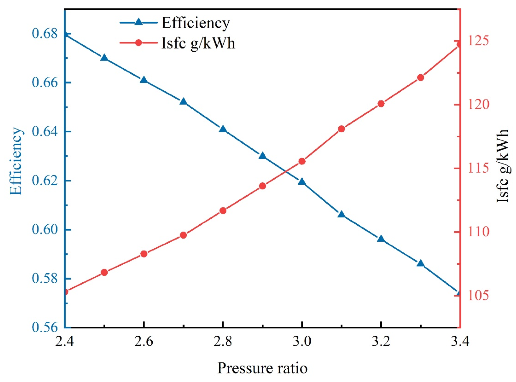
As shown in Figure 4, with other parameters held constant, as the compressor pressure ratio increases from 2.4 to 3.4, the output power of GT decreases from 65 kW to 24 kW, while the output power of the SOFC increases from 175 kW to 179 kW, resulting in a downward trend in total system output power. This occurs because as the compressor pressure ratio rises, the work consumed by the compressor increases, thereby reducing the mechanical output power available from the GT. Meanwhile, the increase in compressor pressure ratio enhances the reversible potential and reduces losses caused by activation and concentration polarization, thereby improving the working voltage and output power of the SOFC. As the mass of the SOFC and its output power are directly proportional, the power-to-weight ratio of the system also shows a declining trend.

Figure 4.
Impact of compressor pressure ratio on system output power and power-to-weight ratio.
As shown in Figure 5, system power-generation efficiency declines with an increase in the ratio of compressor pressure. This happens because as the pressure ratio increases, the outlet temperature of the compressor rises, the preheating required by the SOFC cathode inlet air decreases, and the system’s heat recovery and utilization rate declines, causing a decline in power-generation efficiency. According to Equation (42), when the fuel flow is constant, the specific fuel consumption of the system is inversely proportional to the total power of the system. Therefore, the system’s specific fuel consumption increases in tandem with the increase in the compressor pressure ratio.
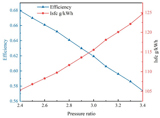
Figure 5.
Impact of compressor pressure ratio on system efficiency and specific fuel consumption.
4.1.2. Impact of Fuel Utilization on SOFC-GT System Performance GT
As shown in Figure 6, as fuel utilization rates increase, the total system output power initially increases and then decreases. When the fuel utilization rate rises from 0.3 to 0.7, the SOFC output power increases from 74 kW to 165 kW, while the GT output power decreases from 125 kW to 62 kW. The increasing trend in the SOFC output power is greater than the decreasing trend in the GT output power, causing an overall increase in system output power. When the fuel utilization rate increases from 0.7 to 0.8, the growth in the SOFC power slows down, and when the fuel utilization rate exceeds 0.8, the SOFC output power decreases; this phenomenon is attributed to concentration polarization effects under high current densities in the SOFC. Figure 7 further reveals the effect of fuel utilization on the SOFC operating voltage and temperature. As the fuel utilization rate increases, the polarization loss in the cell gradually increases, leading to a continuous decrease in the output voltage of the SOFC. In addition, excessive fuel utilization may also lead to high cell temperature, which in turn affects the long-term stability and service life of the SOFC. Under constant fuel flow conditions, increasing fuel utilization means more hydrogen participates in the electrochemical reaction, thereby increasing the proportion of SOFC output power in the hybrid power system. Despite an increase in the hybrid system’s total output power when the fuel utilization rate is less than 0.7, the power-to-weight ratio of the system still shows a downward trend due to the relatively large mass of the SOFC.
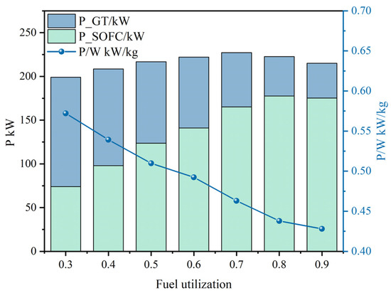
Figure 6.
Impact of fuel utilization on system output power and power-to-weight ratio.
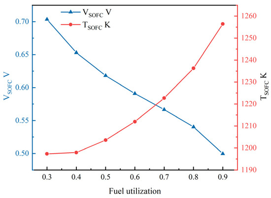
Figure 7.
Impact of fuel utilization on SOFC operating voltage and temperature.
Figure 8 shows the impact of fuel utilization rate on the system’s power generation efficiency and specific fuel consumption. When the fuel utilization rate is too low, it leads to increased internal losses in the SOFC and a large amount of fuel is wasted, at which time the system power-generation efficiency is low and the specific fuel consumption is high. As the fuel utilization rate increases, more fuel is utilized by the SOFC, and the power-generation efficiency of the system increases. When the fuel utilization rate surpasses 0.7, a decline in the system’s power-generation efficiency is observed. This reduction is due to the increasing polarization losses in the fuel cell, which subsequently causes a decline in the SOFC output power, negatively affecting the overall efficiency of the hybrid system. Consequently, to optimize the hybrid system’s operational performance, it is imperative to balance the selection of the fuel utilization rate.

Figure 8.
Impact of fuel utilization rate on system efficiency and specific fuel consumption.
4.1.3. Impact of Fuel Distribution on SOFC-GT System Performance
To optimize the work ratio of the SOFC and GT and enhance the power-to-weight ratio, improving the advantages of the hybrid system, this paper sets up two fuel flow paths: one part enters the SOFC and the other enters the combustion chamber. The proportion of fuel entering the SOFC, and the combustion chamber can be adjusted by regulating the valve openings. As shown in Figure 9, as the proportion of fuel entering the SOFC increases from 0.1 to 1, the SOFC output power increases from 25 kW to 177.7 kW, and the GT output power decreases from 132 kW to 46 kW. Despite the increase in the total system output power, the system power-to-weight ratio still tends to decrease due to the larger mass of the SOFC. Figure 10 further reveals the impact of fuel distribution on the weight of the SOFC and GT. As the proportion of fuel entering the SOFC increases, the weight of the SOFC significantly rises, while the weight of the GT is less sensitive to fuel distribution. Therefore, proper fuel distribution can help address the overall system weight issue. To sustain a high system efficiency and a high power-to-weight ratio in the SOFC-GT hybrid power system, thereby maximizing performance potential, the fuel allocation ratio should be chosen in a compromise.
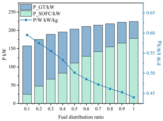
Figure 9.
Impact of fuel distribution ratio on system output power and power-to-weight ratio.
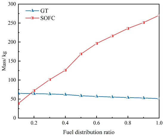
Figure 10.
Impact of fuel distribution ratio on SOFC and GT mass.
Figure 11 shows the influence of the fuel distribution ratio on both the efficiency and the specific fuel consumption within the hybrid system. As the proportion of fuel entering the SOFC increases from 0.1 to 1, system efficiency improves from 0.44 to 0.63, while the specific fuel consumption decreases from 161 g/kWh to 113 g/kWh. This is due to the higher power-generation efficiency of the SOFC compared to the GT, so increasing the proportion of fuel going into the SOFC can effectively enhance the overall power-generation efficiency of the hybrid system and reduce the specific fuel consumption.

Figure 11.
Impact of fuel distribution ratio on system efficiency and specific fuel consumption.
4.1.4. Hybrid Power System Parameter Design
In summary, fuel utilization, compressor pressure ratio, and fuel distribution ratio notably influence the thermodynamic performance and system’s power-to-weight ratio. In this section, the NSGA-II algorithm is employed to identify the optimal input parameters for the SOFC-GT hybrid system, targeting the dual objectives of maximizing power-generation efficiency and the power-to-weight ratio.
Multi-objective optimization involves adjusting the decision variables within an optimization model to either maximize or minimize the objective function values while adhering to a set of constraints. In this study, the decision variables include fuel utilization rate, compression ratio, and fuel distribution ratio. The computational flowchart for the multi-objective optimization of the SOFC-GT hybrid power system is depicted in Figure 12.
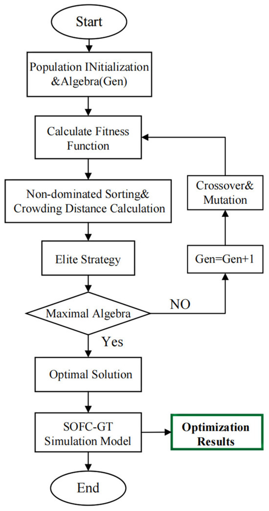
Figure 12.
Multi-objective optimization flowchart.
After performing multi-objective optimization based on NSGA-II, a set of non-dominated solutions, known as the Pareto front, is generated. Figure 13 illustrates the Pareto front, where each solution on the Pareto front is feasible and optimal, except that the system efficiency and the power-to-weight ratio have different weights. In order to select a solution from these optimal solutions that best meets the requirements of practical applications, the linear programming method with multidimensional preference analysis (LINMAP) is used in this study to make a comprehensive decision for these two objectives. By applying the optimized decision variables selected by the LINMAP method to the SOFC-GT hybrid powertrain model, we obtain the optimal power allocation scheme and performance parameters under the given objectives, and the specific results are shown in Table 6.
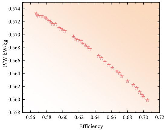
Figure 13.
Target variable Pareto frontier.
Table 6.
Optimized design parameters for SOFC-GT hybrid system.
4.2. SOFC-GT Hybrid System for Aviation Applications
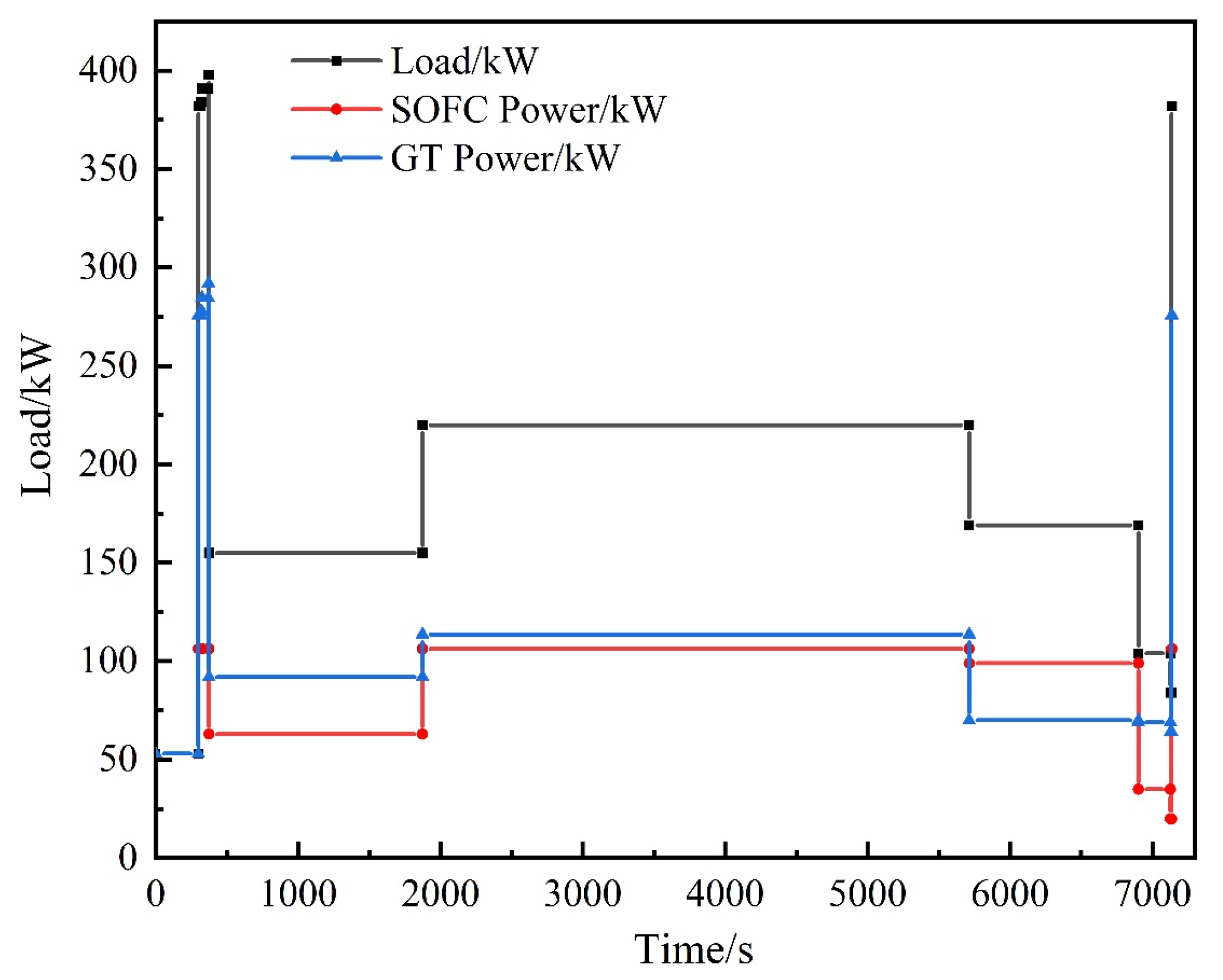
After the parameters of the SOFC-GT hybrid system are determined, this section presents the performance of the hybrid system under variable operating conditions. Under the premise of meeting the load demand, in order to make the hybrid system operate more efficiently, the SOFC is prioritized to be used as the main power output unit, while the GT acts as the auxiliary power. At this point, the excellent performance of high power-generation efficiency of the SOFC can be better utilized, while the mass penalty brought by part of the SOFC can be circumvented by the GT with high power density.
The power density of the SOFC-GT hybrid system is lower compared to traditional internal combustion engines [13]. Consequently, this system has been proposed for use in UAVs, commuter aircraft, and distributed propulsion aircraft [8]. This type of aircraft is highly sensitive to fuel consumption, and the thermal efficiency advantages of the hybrid system will contribute to its extended endurance time. Figure 14 shows the flight profile of a certain long-endurance UAV, in which the aircraft is flying at Mach 0.7 Ma and its cruising altitude is 8840 m. It contains several processes, including taxiing, takeoff, climbing, cruising, descending, and landing. In the traditional aeronautical power system, in order to meet the high power demand during the takeoff and climb phases, the engine is often operated at the maximum power output point, while the cruise phase deviates from the design conditions, and in the actual flight process, the percentage of high power demand time is much lower than that of the cruise phase, which obviously results in an inefficient use and waste of energy [34]. Using a hybrid power system can better utilize the efficiency of SOFCs, thus enhancing overall system efficiency throughout the flight cycle and reducing fuel consumption.
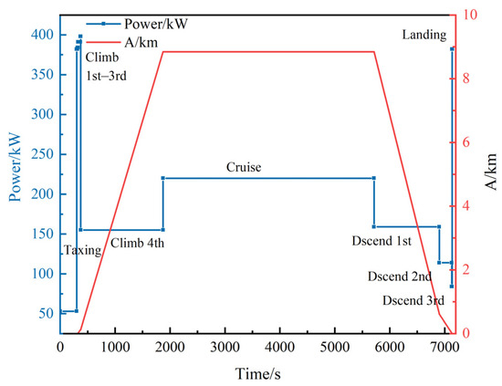
Figure 14.
Long-endurance UAV flight profiles.
Based on the demand load power as shown in Figure 14, a fuzzy logic control energy management strategy was incorporated, resulting in the power allocation of the SOFC-GT hybrid power system throughout the complete flight profiles as depicted in Figure 15. Due to the startup time delay of the SOFC, the taxiing phase power is fully supplied by the GT. During the cruise, the SOFC operates at rated power, with a supplementary fuel injection in the GT for rapidly responding to the transient high power demands during the takeoff and climb phases. Figure 16 illustrates the changes in system efficiency throughout the entire flight mission profile, indicating that the efficiency of the SOFC-GT hybrid system is maintained between 60% and 75% during the major flight cycles, demonstrating superior overall performance. Particularly during the cruise phase, which occupies the longest duration, the system efficiency reaches 65.1%, with a specific fuel consumption of 109.7 g/kWh. The efficiency increases during the cruise phase compared to ground conditions are due to the increased preheating requirement at the SOFC cathode inlet as altitude increases, which in turn enhances the system’s heat recovery utilization efficiency. This is an improvement of over 25% compared to the small internal combustion engine commuter aircraft (below 30%) [35], while also cutting fuel consumption by more than half, highlighting the significant advantages and potential applications of the SOFC-GT hybrid system in aviation propulsion.

Figure 15.
Hybrid power unit power distribution.
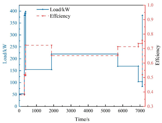
Figure 16.
Hybrid power system efficiency.
5. Conclusions
In this paper, an SOFC-GT hybrid power system fueled by propane is studied, and the impacts of parameters like pressure ratio, fuel utilization, and fuel distribution on the system performance are investigated. The following conclusions are drawn from this study:
- The optimization directions for efficiency and weight in the SOFC-GT hybrid power system are opposite. For the optimized model, the system efficiency reaches 0.621, the specific fuel consumption is 115.2 g/kWh, and the power-to-weight ratio is 0.569 kW/kg.
- The efficiency of the SOFC-GT hybrid power system initially increases and then decreases with the rise in fuel utilization rate (0.1~0.9), while output power proportion of the SOFC increases with higher fuel utilization rates. By reducing the fuel utilization rate, the output power proportion of the SOFC in the hybrid system can be decreased, leveraging the high power-to-weight ratio of the GT to compensate for the mass penalty of the SOFC. To maintain high efficiency and power-to-weight ratio, a fuel utilization rate around 0.6 is advisable.
- As the proportion of fuel entering the SOFC increases, the efficiency of the SOFC-GT hybrid system increases while the power-to-weight ratio decreases. To balance the thermodynamic performance and power-to-weight ratio of the hybrid system, the fuel proportion entering the SOFC should be maintained at around 0.55.
- When the hybrid power system is applied to aircraft power, the system efficiency in the cruise phase can reach 0.651. Compared to traditional aviation power units, the specific fuel consumption can be reduced by more than half, and the flight duration can be more than doubled.
Author Contributions
Conceptualization, Z.C.; methodology, Z.C.; software, Z.C.; validation, Z.C.; formal analysis, Z.C.; investigation, Z.C.; writing—original draft preparation, Z.C.; writing—review and editing, F.L., Z.W. and X.J.; supervision, F.L. and J.M. All authors have read and agreed to the published version of the manuscript.
Funding
This work is supported by the National Defense Science and Technology 173 Program Area Fund—Key Project (No. 2021-JCJQ-JJ-0339), Advanced Aerodynamic Innovation Workstation (HKCX2022-01-002), Aeronautical Science Foundation of China (No. 20230040052004), National Natural Science Foundation of China (No. U2341279), and the Fundamental Research Funds for the Central Universities (501XTCX2023146001).
Data Availability Statement
Data is contained within the article.
Conflicts of Interest
The authors declare no conflict of interest.
Nomenclature
| Nomenclature | System efficiency | ||
| F | Faraday constant (C/mol) | System power-to-weight ratio (kW/kg) | |
| j | Current density (A/cm2) | Specific fuel consumption (g/kWh) | |
| N | Number of cells | SOFC | Solid oxide fuel cell |
| Open-circuit voltage (V) | GT | Gas turbine | |
| Activation polarization (V) | LHV | Lower heating value (kJ/mol) | |
| Concentration polarization (V) | n | Molar flow rate (mol/s) | |
| Ohmic polarization (V) | M | Mass (kg) | |
| Standard potential (V) | Subscripts | ||
| Electrochemical reaction rate | com | Compressor | |
| Fuel utilization rate | comb | Combustion | |
| Fuel distribution ratio | turb | Turbine | |
| S | Active surface area (cm2) | in | Inlet |
| A | Altitude (km) | out | Outlet |
| H | Enthalpy (J) | inv | Inverter |
| h | Specific enthalpy (J/kg) | gen | Generator |
| p | Pressure (Pa) | heat | Heat exchanger |
| P | Power (kW) | ca | Cathode |
| Pressure ratio | an | Anode |
References
- IEA. CO2 Emissions in 2023, IEA, Paris. Licence: CC BY 4.0. 2024. Available online: https://www.iea.org/reports/co2-emissions-in-2023 (accessed on 1 March 2024).
- Kroyan, Y.; Wojcieszyk, M.; Kaario, O.; Larmi, M. Modeling the impact of sustainable aviation fuel properties on end-use performance and emissions in aircraft jet engines. Energy 2022, 255, 124470. [Google Scholar] [CrossRef]
- Bravo-Mosquera, P.D.; Catalano, F.M.; Zingg, D.W. Unconventional aircraft for civil aviation: A review of concepts and design methodologies. Prog. Aerosp. Sci. 2022, 131, 100813. [Google Scholar] [CrossRef]
- Choudhury, A.; Chandra, H.; Arora, A. Application of solid oxide fuel cell technology for power generation—A review. Renew. Sustain. Energy Rev. 2013, 20, 430–442. [Google Scholar] [CrossRef]
- Chung, T.-D.; Chyou, Y.-P.; Hong, W.-T.; Cheng, Y.-N.; Lin, K.-F. Influence of Energy Recuperation on the Efficiency of a Solid Oxide Fuel Cell Power System. Energy Fuels 2007, 21, 314–321. [Google Scholar] [CrossRef]
- Xia, L.; Li, X.; Song, J.; Ren, X.; Gu, C. Design and Analysis of S-CO2 Cycle and Radial Turbine for SOFC Vehicle Waste-Heat Recovery. J. Therm. Sci. 2019, 28, 559–570. [Google Scholar] [CrossRef]
- Bao, C.; Wang, Y.; Feng, D.; Jiang, Z.; Zhang, X. Macroscopic modeling of solid oxide fuel cell (SOFC) and model-based control of SOFC and gas turbine hybrid system. Prog. Energy Combust. Sci. 2018, 66, 83–140. [Google Scholar] [CrossRef]
- Bao, C.; Wang, Y.; Feng, D.; Jiang, Z.; Zhang, X. Design and performance of a compact air-breathing jet hybrid-electric engine coupled with solid oxide fuel cells. Front. Energy Res. 2021, 8, 613205. [Google Scholar] [CrossRef]
- Braun, R.J.; Gummalla, M.; Yamanis, J. System Architectures for Solid Oxide Fuel Cell-Based Auxiliary Power Units in Future Commercial Aircraft Applications. J. Fuel Cell Sci. Technol. 2009, 6, 031015. [Google Scholar] [CrossRef]
- Himansu, A.; Freeh, J.E.; Steffen, C.J., Jr.; Tornabene, R.T.; Wang, X.-Y.J. Hybrid solid oxide fuel cell/gas turbine system for high altitude long endurance aerospace missions. In Proceedings of the International Conference on Fuel Cell Science, Engineering and Technology, Irvine, CA, USA, 19–21 June 2006; Volume 42479, pp. 573–583. [Google Scholar] [CrossRef]
- Yanovskiy, L.S.; Baykov, A.V.; Raznoschikov, V.V.; Averkov, I.S. Alternative Fuels and Perspectives Solid Oxide Fuel Cells Usage in Air Transport. ECS Trans. 2013, 57, 149–160. [Google Scholar] [CrossRef]
- Liu, H.; Qin, J.; Ji, Z.; Guo, F.; Dong, P. Study on the performance comparison of three configurations of aviation fuel cell gas turbine hybrid power generation system. J. Power Sources 2021, 501, 230007. [Google Scholar] [CrossRef]
- Collins, J.M.; McLarty, D. All-electric commercial aviation with solid oxide fuel cell-gas turbine-battery hybrids. Appl. Energy 2020, 265, 114787. [Google Scholar] [CrossRef]
- Valencia, E.A.; Hidalgo, V.; Panagiotis, L.; Nalianda, D.; Singh, R.; Liu, C. Design Point Analysis of an Hybrid Fuel Cell Gas Turbine Cycle for Advanced Distributed Propulsion Systems. In Proceedings of the 51st AIAA/SAE/ASEE Joint Propulsion Conference, Orlando, FL, USA, 27–29 July 2015. [Google Scholar] [CrossRef]
- Yin, F.; Rao, A.G.; Bhat, A.; Chen, M. Performance assessment of a multi-fuel hybrid engine for future aircraft. Aerosp. Sci. Technol. 2018, 77, 217–227. [Google Scholar] [CrossRef]
- Sarmah, P.; Gogoi, T. Performance comparison of SOFC integrated combined power systems with three different bottoming steam turbine cycles. Energy Convers. Manag. 2017, 132, 91–101. [Google Scholar] [CrossRef]
- Deng, M.; Liu, J.; Zhang, X.; Li, J.; Fu, L. Energy and Parameter Analysis of SOFC System for Hydrogen Production from Methane Steam Reforming. J. Therm. Sci. 2022, 31, 2088–2110. [Google Scholar] [CrossRef]
- Eveloy, V.; Rodgers, P.; Qiu, L. Integration of an atmospheric solid oxide fuel cell—Gas turbine system with reverse osmosis for distributed seawater desalination in a process facility. Energy Convers. Manag. 2016, 126, 944–959. [Google Scholar] [CrossRef]
- Park, S.H.; Lee, Y.D.; Ahn, K.Y. Performance analysis of an SOFC/HCCI engine hybrid system: System simulation and thermo-economic comparison. Int. J. Hydrogen Energy 2014, 39, 1799–1810. [Google Scholar] [CrossRef]
- Hou, L.-Y.; Dong, N.; Ren, Z.-Y.; Zhang, B.; Hu, S.-L. Cooling and coke deposition of hydrocarbon fuel with catalytic steam reforming. Fuel Process. Technol. 2014, 128, 128–133. [Google Scholar] [CrossRef]
- Aziz, M.; Darmawan, A.; Juangsa, F.B. Hydrogen production from biomasses and wastes: A technological review. Int. J. Hydrogen Energy 2021, 46, 33756–33781. [Google Scholar] [CrossRef]
- Antolini, E. Direct propane fuel cells. Fuel 2022, 315, 123152. [Google Scholar] [CrossRef]
- Bove, R.; Lunghi, P.; Msammes, N. SOFC mathematic model for systems simulations. Part one: From a micro-detailed to macro-black-box model. Int. J. Hydrogen Energy 2005, 30, 181–187. [Google Scholar] [CrossRef]
- Aguiar, P.; Adjiman, C.S.; Brandon, N.P. Anode-supported intermediate temperature direct internal reforming solid oxide fuel cell. I: Model-based steady-state performance. J. Power Sources 2004, 138, 120–136. [Google Scholar] [CrossRef]
- Costamagna, P.; Magistri, L.; Massardo, A.F. Design and part-load performance of a hybrid system based on a solid oxide fuel cell reactor and a micro gas turbine. J. Power Sources 2001, 96, 352–368. [Google Scholar] [CrossRef]
- Huang, Y.; Turan, A. Fuel sensitivity and parametric optimization of SOFC—GT hybrid system operational characteristics. Therm. Sci. Eng. Prog. 2019, 14, 100407. [Google Scholar] [CrossRef]
- NOAA. U.S. Standard Atmosphere 1976; National Oceanic and Amospheric Administration: Washington, DC, USA, 1976. [Google Scholar]
- Saebea, D.; Patcharavorachot, Y.; Assabumrungrat, S.; Arpornwichanop, A. Analysis of a pressurized solid oxide fuel cell–gas turbine hybrid power system with cathode gas recirculation. Int. J. Hydrogen Energy 2013, 38, 4748–4759. [Google Scholar] [CrossRef]
- Haseli, Y.; Dincer, I.; Naterer, G. Thermodynamic modeling of a gas turbine cycle combined with a solid oxide fuel cell. Int. J. Hydrogen Energy 2008, 33, 5811–5822. [Google Scholar] [CrossRef]
- George, R.A. Status of tubular SOFC field unit demonstrations. J. Power Sources 2000, 86, 134–139. [Google Scholar] [CrossRef]
- Cirigliano, D.; Frisch, A.M.; Liu, F.; Sirignano, W.A. Diesel, spark-ignition, and turboprop engines for long-duration unmanned air flights. J. Propuls. Power 2018, 34, 878–892. [Google Scholar] [CrossRef]
- Navasa, M.; Graves, C.; Chatzichristodoulou, C.; Løye, T.; Sund, B. A three dimensional multiphysics model of a solid oxide electrochemical cell: A tool for understanding degradation. Int. J. Hydrogen Energy 2018, 43, 11913–11931. [Google Scholar] [CrossRef]
- Veyo, S.E.; Shockling, L.A.; Dederer, J.T.; Gillett, J.E.; Lundberg, W.L. Tubular Solid Oxide Fuel Cell/Gas Turbine Hybrid Cycle Power Systems: Status. J. Eng. Gas Turbines Power 2002, 124, 845–849. [Google Scholar] [CrossRef]
- Zountouridou, E.; Kiokes, G.; Dimeas, A.; Prousalidis, J.; Hatziargyriou, N. A guide to unmanned aerial vehicles performance analysis—The MQ-9 unmanned air vehicle case study. J. Eng. 2023, 2023, e12270. [Google Scholar] [CrossRef]
- Stoia, T.; Balan, C.; Atreya, S.; O’Neil, P. Solid Oxide Fuel Cell—Steam Reformation Power System Configuration Options for an All-Electric Commuter Airplane Flight Demonstrator. In Proceedings of the 2018 Aviation Technology, Integration, and Operations Conference, Atlanta, GA, USA, 25–29 June 2018; p. 3358. [Google Scholar] [CrossRef]


Disclaimer/Publisher’s Note: The statements, opinions and data contained in all publications are solely those of the individual author(s) and contributor(s) and not of MDPI and/or the editor(s). MDPI and/or the editor(s) disclaim responsibility for any injury to people or property resulting from any ideas, methods, instructions or products referred to in the content. |
© 2024 by the authors. Licensee MDPI, Basel, Switzerland. This article is an open access article distributed under the terms and conditions of the Creative Commons Attribution (CC BY) license (https://creativecommons.org/licenses/by/4.0/).