Review

Defect Engineering of Nickel-Based Compounds for Energy-Saving H2 Production

1
School of Chemistry and Chemical Engineering, Chongqing University of Technology, Chongqing 400054, China
2
Chongqing Institute of Green and Intelligent Technology, Chinese Academy of Sciences, Chongqing 400714, China
3
College of Environmental Science and Engineering, Donghua University, Shanghai 201620, China
4
Key Laboratory of Modern Agricultural Equipment and Technology, Ministry of Education, School of Agricultural Engineering, Jiangsu University, Zhenjiang 212013, China
5
Radiation Technology Institute, Beijing Academy of Science and Technology, Beijing 100875, China
*
Authors to whom correspondence should be addressed.
Energies 2024, 17(15), 3801; https://doi.org/10.3390/en17153801
Submission received: 10 July 2024 / Revised: 30 July 2024 / Accepted: 30 July 2024 / Published: 2 August 2024

Abstract

:
The urea oxidation reaction (UOR), requiring less energy to produce hydrogen, is considered as a potential alternative to the traditional oxygen evolution reaction. Consequently, developing highly efficient UOR catalysts to facilitate H2 production has garnered widespread attention. A promising approach to enhancing the effectiveness of these electrocatalysts is defect engineering. By introducing structural defects, defect engineering can expose more active sites and optimize their electronic structure, thereby improving their activity. This work offers a comprehensive overview of recent progress in defect engineering of nickel-based electrocatalysts for the UOR. It summarizes various strategies for generating defects, including the creation of vacancies, doping, the incorporation of single atoms, amorphization, and achieving high refractivity. Furthermore, we discuss the advanced characterization techniques commonly used to identify the presence of defects in these electrocatalysts, as well as to determine their detailed structures. Finally, we outline the prospects and challenges associated with the systematic design and fabrication of novel UOR electrocatalysts with tunable defects, aiming to further enhance their efficiency and stability.

1. Introduction

The severe environmental degradation and non-renewability associated with conventional fossil fuels have spurred aspirations for advancing a new generation of renewable energy devices, underpinned by cleaner technologies [1,2,3,4,5]. Among most clean energy alternatives, H2 emerges as a frontrunner, esteemed for its efficiency and environmental benignity [6,7,8,9]. Hydrogen fuel cells, pivotal in harnessing H2 energy, have garnered widespread attention for their zero-emission attributes and heightened efficiency, rendering them an appealing substitute for conventional energy sources. Nevertheless, the attainment of commercial viability for hydrogen fuel cells hinges significantly on the advancement of H2 production. Currently, methods for H2 production primarily involve steam reforming, coal gasification, biological methods, and electrolysis of water [10,11,12,13]. Among them, the quest of water electrolysis for H2 production has attracted considerable attention due to its environmentally friendly and highly efficient characteristics. Traditional water electrolysis consists of two half-reactions, the oxygen evolution reaction (OER) at the anode and the hydrogen evolution reaction (HER) at the cathode, producing oxygen and hydrogen, respectively. However, conventional water electrolysis for H2 generation encounters a substantial impediment: the OER process involves complex multiple electron transfer process with slow reaction kinetics, thus requiring high potentials [14,15,16,17]. To circumvent this challenge, researchers have introduced certain thermodynamically less-stable oxidizable substances, such as urea, into the electrolyte to mitigate the energy barrier associated with the anodic reaction [18,19,20,21]. Replacing the OER with a UOR accelerates the water-splitting process [22,23,24,25]. The formulas for the traditional water electrolysis setup, including the anodic OER (Equation (1)) and the cathodic HER (Equation (2)), are as follows:
4OH → O2 + 2H2O + 4e
2H2O + 2e → H2 + 2OH
2H2O → 2H2 + O2
The OER and HER have theoretical potentials of 0.4 V and −0.83 V vs. RHE, respectively. Consequently, the calculated potential necessary for the full electrolysis of water is 1.23 V (Equation (3)). The formulas for the traditional urea electrolysis setup, comprising the anodic UOR (Equation (4)) and the cathodic HER (Equation (5)) [26,27,28,29,30,31], are presented as follows:
CO(NH2)2 + 6OH → CO2 + N2 + 5H2O + 6e
2H2O + 2e → H2 + 2OH
CO(NH2)2 + H2O → 3H2 + CO2 + N2
The calculated voltage for the entire urea electrolysis process is merely 0.37 V (Equation (6)), markedly lower than the 1.23 V necessary for water electrolysis. Although the UOR involves a complex six-electron transfer mechanism that results in slow kinetics, this issue can be mitigated by developing efficient catalysts. However, the inherently lower theoretical potential of the UOR is regarded as a distinct advantage. Therefore, there is an urgent need to develop catalysts for the UOR that are both efficient and durable to maximize its practical application performance. Noble metal catalysts, including platinum and ruthenium, exhibit outstanding performance as catalysts for electrode reactions [32,33,34]. Nevertheless, their exorbitant cost and constrained accessibility have spurred researchers to investigate alternative non-noble metal catalysts. Among various UOR electrocatalysts, nickel is one of the most extensively studied transition metals due to its cost-effectiveness and excellent performance in the UOR [35,36,37,38].
Currently, extensive research has been conducted on nickel-based materials, which are abundant, cost-effective, and efficient [39,40,41,42,43]. The application of defect engineering in Ni-based materials has significantly enhanced the intrinsic activity of the catalysts. Defect engineering is a classic case of catalyst design. In solid materials, defects can be classified based on their morphology and properties within the crystalline structure, including point defects, line defects, planar defects, and volumetric defects. The intentional introduction of defects allows for the modulation of the catalyst’s electronic and surface properties, manipulation of the material’s structure and composition, and alteration of its physical and chemical properties, thereby enhancing the catalyst’s activity. In catalysis, molecules of reactants need to adsorb onto the catalyst surface before undergoing chemical reactions to produce products. Defects on the catalyst surface can provide active sites, enabling reactant molecules to initiate chemical reactions while being adsorbed, thereby rendering the catalyst more active. The principle behind this lies in the fact that defects generate unsaturated coordination sites, which are more reactive compared to fully coordinated sites. In addition to altering the active sites, defect engineering can also modulate the electronic makeup of the catalyst, adjusting the interactions between the catalyst and reactants, lowering the activation energy, and enhancing catalytic activity. In summary, defect engineering has become a potent strategy for boosting catalyst activity and stability in the field of catalysis. However, its meaningful application in electrochemical UORs remains relatively limited. Therefore, reviewing recent advancements in utilizing defect engineering for Ni-based catalysts in assisting hydrogen production remains of significant importance.
This review summarizes recent advancements in defect-engineered nickel-based catalysts aimed at enhancing UOR efficiency, ultimately aimed at enhancing H2 generation efficiency. Furthermore, it provides an in-depth examination of associated characterization techniques. Specifically, the types of defects present in nickel-based catalysts are introduced and discussed (Figure 1), with a comparative analysis of various defect strategies (Table 1). It also summarizes common preparation methods and the types of defects formed (Table 2). Subsequently, this review presents the main characterization methods employed to ascertain the presence, structure, and prevalence of defects in the developed electrocatalysts.

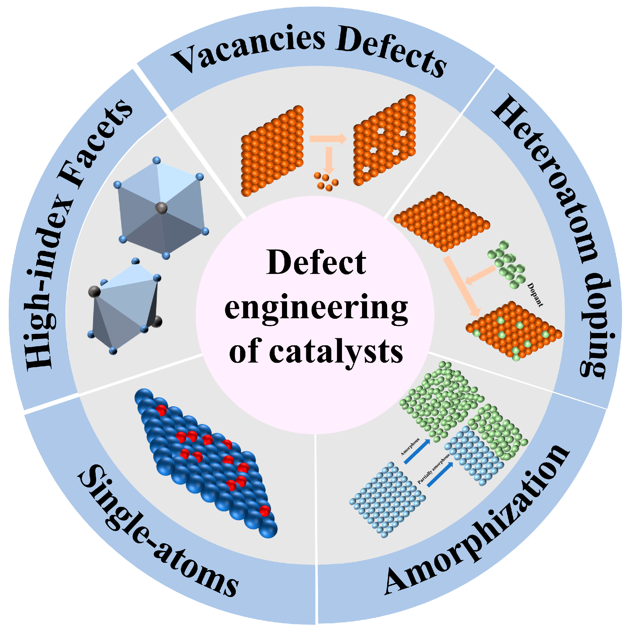
2. Defect Engineering of Catalysts

2.1. Vacancy Defects

Introducing vacancy defects is considered an effective method for controlling the atomic and electronic structure of catalysts. Vacancies contain abundant localized electrons, which can not only anchor individual atoms but also adjust the bonding strength of metal adsorbates, enabling rapid exchange of intermediates and thus achieving excellent electrocatalytic performance. Therefore, creating vacancies can effectively enhance UOR activity. Complex characterization methods are crucial for identifying the types and quantities of defects in electrocatalysts and for gaining a thorough understanding of how these flaws influence catalytic performance. For instance, advanced aberration-corrected high-resolution transmission electron microscopy (AC-HRTEM) enables direct visualization of materials at the atomic scale, facilitating the identification of various defects in electrocatalysts. Qin et al. [58] first employed EDX elemental mapping to provide direct observational evidence of the uniform distribution of O, Ni, and V elements (Figure 2a). Subsequently, they conducted a detailed structural analysis of HRTEM images of the V-doped catalysts, revealing that catalysts with different V doping concentrations exhibited varying numbers of exposed facets and point defects (indicated by white dashed circles) (Figure 2b). Furthermore, by comparing the 3D pseudo-color surface maps of the catalysts before and after V doping, they found that the surface roughness increased after V doping, indicating that the lattice exhibited relatively random interruptions by defects (Figure 2c,d). These findings indicate that the improvement in the specific surface area and active sites of Ni(OH)2 stems from the successful doping of V and the introduction of numerous defects through doping. Among all types of vacancies, the energy required to form oxygen vacancies is extremely low, which renders them the predominant type of anion vacancies. The presence of oxygen vacancies may modify the physicochemical characteristics of catalysts. For instance, it is feasible to modulate the electronic configuration of the catalyst through regulating the quantity of oxygen vacancies, as well as the active catalytic regions and the affinity of reactants for adsorption [75]. Researchers have reported the use of oxygen vacancies to improve the catalytic efficiency of catalysts in UORs, as demonstrated by Qiu et al. [44]; NiMoO4 modified with phosphate was prepared using a simple etching method mediated by polyoxometalate, leading to the formation of mesh-like nanostructures and numerous oxygen vacancies on nickel foam (NF, Figure 2e). The resultant catalyst exhibited remarkable HER efficacy, achieving 116 mV at 10 mA cm−2 and a Tafel slope of 77.5 mV dec−1 (Figure 2f). Similarly, it exhibited significant UOR activity, achieving 1.359 V at 10 mA cm−2, alongside a Tafel slope measuring 19.3 mV dec−1 (Figure 2g). Moreover, compared to traditional water electrolysis, the NF/P-NiMoO4−x electrode required just 1.48 V to reach an equivalent current density to traditional water electrolysis, which needed 1.66 V (Figure 2h). Furthermore, the electrolytic cell composed of NF/P-NiMoO4−x||NF/P-NiMoO4−x exhibited reductions in overpotentials by 30 mV at 10 mA cm−2 and 80 mV at 50 mA cm−2, compared to the cell composed of Ir/C||Pt/C in urea electrolysis. Furthermore, it demonstrated superior long-term durability over 50 h compared to Ir/C and Pt/C. The introduction of oxygen vacancies increased the defect energy close to the Fermi level, significantly boosting the electrical conductivity of NF/P-NiMoO4−x. This improvement accelerates the electrocatalysis of both HER and UOR kinetics.
The properties of metal compounds are influenced not only by anion vacancies but also significantly by cation vacancies. Cation vacancies possess unique characteristics due to their distinct electron and orbital distributions. However, cation vacancies have a higher formation energy compared to anion vacancies, making the study of their effects more challenging. Xu et al. [45] synthesized a novel nickel–zinc bimetallic nanosheet bifunctional electrocatalyst (ZnO-Ni2P) on NF (Figure 2i). During the preparation process, the incorporation of zinc resulted in the formation of a heterostructure composed of Ni2P and ZnO. ZnO can attract electrons from Ni atoms and transfer them to P atoms, leading to the formation of Ni cation vacancies and P anion vacancies, which characterizes ZnO as an ‘electron pump’. Ni vacancies facilitate the oxidation of Ni2+ to higher oxidation states, facilitating the oxidation of urea molecules. Concurrently, P vacancies enhance charge transfer, thereby promoting effective adsorption and activation of H* intermediates. Meanwhile, the prepared catalyst shows excellent effectiveness in UORs and HERs (Figure 2j,k). In UOR measurements, it achieved 50 mA cm−2 at 1.347 V, and then it achieved 10 mA cm−2 at 68 mV for HER tests. Furthermore, the electrolytic cell was constructed using ZnO-Ni2P/NF||ZnO-Ni2P/NF in an electrolyte composed of 1 M KOH with 0.33 M urea. The applied potentials were 1.424 V at 10 mA cm−2 and 1.529 V at 50 mA cm−2, demonstrating good performance (Figure 2l).

2.2. Heteroatom Doping

Doping has found extensive application in the synthesis of various electrocatalysts. By introducing dopant atoms, electron structure can be adjusted, facilitating the redistribution of electron density. Additionally, the incorporation of dopant atoms facilitates the formation of surface defects, thereby enhancing the binding affinity with urea molecules and reaction intermediates. Consequently, dopant atom doping stands as a widely utilized approach to enhance electrocatalytic performance. The success of doping can be intuitively determined through physical characterization. For instance, X-ray photoelectron spectroscopy (XPS) is an exceptionally precise method of spectroscopy. It can detect the chemical and electronic states on material surfaces. Defects can alter the binding energies of elements in the original material or even introduce new binding energies, leading to slight shifts in the XPS peaks or the appearance of new peaks.
Liu et al. [76] prepared Co-doped α-Ni(OH)2 and utilized XPS to verify the effective doping of Co atoms into α-Ni(OH)2. The characterization of the material involved an examination of alterations in both the chemical state and the composition at the surface of the samples. The presence of Ni, Co, and O elements in Co-doped α-Ni(OH)2 was confirmed through comprehensive spectrum analysis. In the high-resolution XPS spectrum of the Co-doped samples, the peak corresponding to Ni 2p3/2 shifted towards higher binding energies, suggesting a modification in the oxidation state of nickel induced by cobalt doping (Figure 3a). The Co 2p3/2 XPS spectrum indicates that the average oxidation state of Co exceeds +2. The area ratio of Co2+ to Co3+ suggests the presence of cobalt in various oxidation states, further confirming the successful incorporation of cobalt through doping (Figure 3b). By fitting the high-resolution XPS spectrum of O 1s into three peaks, corresponding to Ni-O bonds, oxygen vacancies or defect edge oxygen atoms, and intercalated species oxygen atoms, it was observed that the relative area of Ni-O decreased while that of O2 increased for the Co-doped samples (Figure 3c). This suggests that Co doping led to a change in the ratio of Ni2+ to Ni3+ and the formation of oxygen vacancies or defects. This confirmed that Co doping not only altered the oxidation state of Ni but also affected the electronic structure and defect state of the samples. Liu et al. [46] utilized a single-step electrodeposition method to grow manganese-doped Ni(OH)2 nanosheets on carbon paper (CP) electrodes (Figure 3d), yielding a homogeneous and extensive catalyst layer. This methodology represents a scalable approach to electrode manufacturing. The resultant electrodes exhibit highly efficient activity in both the UOR and the HER. Theoretical calculations indicate that manganese doping facilitates the transition of Ni(II) to Ni(III), thus improving the chemisorption of urea and boosting UOR efficiency. The nanosheet’s interconnected structure offers more active sites, which are beneficial throughout the reaction process, facilitating electron and reactant molecule (urea) transfer. EDX (Energy-dispersive X-ray spectroscopy) mapping confirms the uniform manganese doping within the Ni(OH)2. The obtained electrodes exhibit outstanding electrocatalytic activity. In alkaline solutions containing urea, achieving 10 mA cm−2 requires only 1.347 V vs. RHE. Similarly, 100 mA cm−2 is attained at 1.427 V vs. RHE (Figure 3e). Subsequent testing of the HER activity of the Mn-Ni(OH)2/CP electrode revealed that it achieved a current density of 10 mA cm−2 at −76 mV, outperforming the Pt/C/CP electrode, which required −39 mV to reach 10 mA cm−2 (Figure 3f). Finally, the authors used a Mn-Ni(OH)2||Mn-Ni(OH)2 electrolytic cell to investigate the urea electrolysis activity. In an electrolyte containing urea, the voltage required to achieve 10 mA cm−2 is 1.407 V, whereas in pure water, the same current requires 1.61 V (Figure 3g). The long-term stability of urea electrolysis was evaluated through time-resolved potential measurements, showing consistent stability even after 12 h of operation. This validates the exceptional stability exhibited by Mn-doped Ni(OH)2 during urea electrolysis. The superior catalytic activity of the catalyst is closely associated with Mn element doping: Firstly, the introduction of Mn ions initiates transformations in the morphology and configuration of Ni(OH)2, fostering the creation of interwoven nanosheet layers. These layers can promote the formation of more active sites, facilitating the generation of high-valence Ni. Secondly, according to DFT calculations, the introduction of Mn induces changes in the electron density distribution of Ni(OH)2. This alteration diminishes the energy threshold needed to facilitate the formation of high-valence Ni, consequently amplifying the activity of UOR. Furthermore, Mn doping facilitates easier adsorption of urea molecules on Mn-Ni(OH)2 surface, resulting in improved UOR activity.
In addition to metallic doping, non-metallic doping represents an efficacious strategy for augmenting UOR activity. Yuan et al. [47] synthesized a phosphorized cobalt nanowire core@shell heterostructure array, decorated with nickel phosphide nanosheets and sulfur-doped at the interface (S-Co2P@Ni2P) (Figure 4a), for applications in the HER and UOR. Both experimental and theoretical investigations affirm that sulfur doping at the interface facilitates the migration of charges from the interior Co2P to the exterior Ni2P, consequently prompting a redistribution of electrons at the interface Co and Ni centers. This orchestrated electron redistribution enhances the adsorption energies of active species during both HER and UOR, thereby bolstering catalytic kinetics and ultimately endowing the prepared catalyst with exceptional electrochemical performance.
Specifically, in the context of the HER, a minimal overpotential of 103 mV is adequate to reach a current output of 100 mA cm−2, while for the UOR, an equivalent current density can be attained with a voltage of 1.36 V (vs. RHE) (Figure 4b,c). To further analyze the electrode’s effectiveness in catalyzing HERs, the authors integrated the S-Co2P@Ni2P electrode into the urea electrolysis setup. This resulted in achieving 10 mA cm−2 at a relatively moderate 1.43 V in the electrolytic cell, notably below the voltage needed for water electrolysis (1.52 V) (Figure 4d). Sulfur doping alters the electronic structure of the metal center at the interface, thereby enhancing the catalytic performance of S-Co2P@Ni2P. Comprehensive physical characterizations and DFT calculations corroborate the pivotal role of sulfur doping in this context: at the interface of S-Co2P@Ni2P, the introduction of sulfur doping initiates a redistribution of electrons. This alteration thermodynamically enhances reactant adsorption and product desorption, consequently enhancing the kinetics of the UOR (Figure 4e). Following sulfur doping, a marked augmentation in positive charge is discerned in the Co centers at the interface of the heterogeneous S-Co2P@Ni2P structure, which plausibly serve as active sites for the UOR.
Since the discovery of single-atom doping, researchers have chosen to co-dope two or more atoms into nickel-based catalysts to further enhance their catalytic performance. A solid NiMoO4 nanorod array on an NF substrate was synthesized using a hydrothermal method by Guo et al. [48]. Afterward, submerging the NiMoO4 nanorod array into an aqueous solution containing Ru facilitated the creation of Ru-NiMoO4@NF nanorods (Figure 4f). After this, a multi-channel Ru/P co-doped hollow NiMoO4@NF nanorod (Ru/P-NiMoO4@NF) was prepared via a thermal phosphorylation reaction. The catalyst exhibited bifunctional electrocatalytic activity, driving high current density towards both the HER and UOR directions in an alkaline seawater electrolyte. Specifically, the optimized Ru/P-NiMoO4@NF demonstrated remarkable performance. For the HER, it achieved a working potential of 3000 mA cm−2 with a voltage of 0.23 mV (vs. RHE). For the UOR, it reached a working potential of 1000 mA cm−2 with 1.46 V (vs. RHE) in an alkaline seawater electrolyte (Figure 4g,h). The electrolyzer composed of Ru/P-NiMoO4@NF||Ru/P-NiMoO4@NF for urea electrolysis achieved impressive results. The system reached 500 mA cm−2 at an exceptionally low voltage requirement of only 1.73 V (Figure 4i). Furthermore, it sustained a current density exceeding 100 mA cm−2 for an extended period, lasting up to 145 h. Analysis of the Ru/P-NiMoO4@NF samples’ XRD patterns at varying Ru concentrations demonstrated the absence of addition besides NiMoO4 and the Ni substrate (Figure 4j). This observation suggests the effective incorporation of Ru and P into NiMoO4 without the formation of novel phases.

2.3. Amorphization

Amorphous catalysts exhibit unique characteristics not found in crystalline catalysts, including isotropic atomic environments that differ markedly from the structured arrangements of crystalline counterparts. These traits confer excellent electrochemical performance upon amorphous catalysts, particularly in the UOR process, where they are more prone to initiating in situ structural reconstruction, thereby accelerating the formation of electroactive species. Raman spectroscopy, by analyzing the molecular vibration modes of materials, can identify amorphous regions, lattice defects, and changes in chemical bonds within crystal structures, thereby providing direct spectroscopic evidence for determining the types and concentrations of defects in materials. Cao et al. [77] designed a crystalline NiO–amorphous CrOx mixed oxide electrocatalyst (NiO-CrOx) through a simple hydrothermal and oxidation process. In situ Raman analysis confirmed the facilitation of NiO reconstruction into active NiOOH species and enhanced urea molecule adsorption by the presence of the amorphous CrOx phase. The authors conducted a comparative tracking of NiO-CrOx and NiO during the reaction process. The results showed that for NiO, the peak corresponding to NiOOH could only be observed when the voltage increased to 1.5 V (vs. RHE), and the peak intensity was relatively low. However, peaks corresponding to NiO and urea were observed at 1.25 V for NiO-CrOx. At 1.3 V, the NiO peak vanished, giving way to the NiOOH peak, identified as the primary active site for the UOR. This result indicates that the addition of amorphous CrOx promotes the transformation of NiO into NiOOH. The findings of other researchers also support the conclusion that amorphous CrOx promotes the transformation of NiO into NiOOH. For instance, Xu et al. [78] obtained Ni/NiO@CrOx through hydrothermal hydrogenation of nickel foam and utilized in situ Raman spectroscopy to elucidate the role of amorphous CrOx during the UOR process. They conducted in situ Raman measurements on NiO, Ni/NiO, and Ni/NiO@CrOx, revealing that at lower potentials, characteristic peaks corresponding to Ni(II)-O were detected. As the potential increased, new characteristic peaks corresponding to Ni(III)-O appeared. However, there were significant differences in the potentials required for generating NiOOH species among three catalysts. Ni/NiO exhibited a reduced potential (1.354 V vs. RHE) compared to NiO (1.364 V vs. RHE), while Ni/NiO@CrOx demonstrated the lowest potential for triggering the formation of NiOOH species (1.334 V vs. RHE) (Figure 5a–c). The presence of metallic Ni and CrOx was observed to enhance the catalytic performance of NiO in the UOR. At 1.334 V, in situ Raman characterization of Ni/NiO@CrOx over various time intervals revealed the emergence and evolution of peaks. These peaks are associated with the stretching vibrations at 471 cm−1 and bending vibrations at 554 cm−1 of NiOOH (Figure 5d). This indicates that dynamic surface structural changes are related to NiOOH species. Peaks corresponding to Cr-O bonds also evolved with potential and time, eventually disappearing, suggesting restructuring of the Ni/NiO@CrOx surface. In conclusion, during the UOR process, the dynamic changes and surface reconstruction of Ni/NiO@CrOx are associated with the formation of the active NiOOH species. The presence of amorphous CrOx promotes the generation of NiOOH species, thereby enhancing both the catalytic activity and stability in UOR, consistent with previous conclusions.
Chen et al. [49] created NF coated with amorphous nickel selenide deposited on Ni(OH)2 nanosheets (Figure 6a). The incorporation of sulfur into nickel selenide increases the electroactive surface area and enhances its affinity for water, thereby providing ideal adsorption sites for hydrogen atoms. This property bestows the Ni-S-Se/NF catalyst with remarkable performance in the HER, as evidenced by overpotentials of 98 mV and 206 mV (vs. RHE) at 10 and 100 mA cm−2 (Figure 6b), respectively. Due to the in situ generation of amorphous hydroxides as the true active components, the Ni-S-Se/NF demonstrates outstanding UOR activity, with electrode potentials reaching 1.38 V (vs. RHE) at 10 mA cm−2 and 1.42 V (vs. RHE) at 100 mA cm−2. At 200 mA cm−2, the UOR potential is approximately 190 mV lower than the OER potential, indicating that urea electrolysis requires lower energy (Figure 6c). To assess the effectiveness of Ni-S-Se/NF in catalyzing H2 production via urea oxidation, a comprehensive electrolytic configuration was devised, incorporating dual Ni-S-Se/NF electrodes. Testing conducted in a solution of 1 M KOH and 0.5 M urea revealed that as the current density increased from 10 mA cm−2 to 100 mA cm−2, and then to 200 mA cm−2, the cell voltage correspondingly escalated from 1.47 V to 1.60 V, ultimately reaching 1.66 V. Notably, these voltages exhibited a significant decrement compared to those requisites for water decomposition (1.57, 1.74, and 1.81 V, Figure 6d), thereby accentuating the efficacy of urea oxidation in mitigating hydrogen production energy consumption. Moreover, via sustained current assessments, the researchers assessed the resilience of Ni-S-Se/NF within HER-UOR electrolytic settings. After 24 h of electrolysis, the cell voltage increased by only 20 mV, a minor increment that indicates the excellent durability of Ni-S-Se/NF during urea-assisted water electrolysis for H2 production, thereby confirming its potential as an efficient and reliable electrode material. They posit that within the catalyst composition, the presence of sulfur in Ni-S-Se/NF plays a pivotal role in augmenting HER activity. Additionally, in the context of the UOR process, the hydroxide species originating from sulfur-substituted selenide stands as the predominant active entity. Structurally, amorphous catalysts exhibit a propensity for revealing a larger quantity of active sites relative to their crystalline counterparts, coupled with notable attributes of flexibility and inherent self-repair mechanisms. In addition to fabricating amorphous catalysts, doping crystalline catalysts with amorphous compounds to utilize their synergistic effects for enhancing the electrochemical activity of catalysts is also a common strategy. Qiao et al. [50] successfully synthesized a hierarchical structured composite material of crystalline nickel cobalt phosphide/amorphous phosphorus-doped manganese oxide (c-CoNiPx/a-P-MnOy) through hydrothermal and high-temperature phosphorization methods (Figure 6e). This composite material exhibits excellent HER and UOR activity in alkaline media. Specifically, when evaluated in a 1 M KOH solution, the overpotentials required to reach 10, 100, and 500 mA cm−2 were 100, 184, and 321 mV, respectively (Figure 6f). During electrochemical performance testing, the potential required for the OER to achieve a current density of 100 mA cm−2 is 1.623 V (vs. RHE), which is 273 mV higher than that required for the UOR (Figure 6g). This indicates that the UOR can replace the OER in traditional water electrolysis, thus reducing the energy required to produce H2. Further comparative experiments showed that when using c-CoNiPx/a-P-MnOy in dual roles as cathode and anode for water electrolysis and urea electrolysis, the urea electrolysis system requires 330 mV less battery voltage to achieve 100 mA cm−2 compared to the water electrolysis system (Figure 6h). The amorphous P-MnOy possesses numerous active sites, promoting the adsorption of urea and water molecules, thereby exhibiting higher catalytic activity. Additionally, the combination of the amorphous P-MnOy with the high conductivity and electron transfer capability of the crystalline CoNiPx makes c-CoNiPx/a-P-MnOy an efficient catalyst for both UOR and HER.

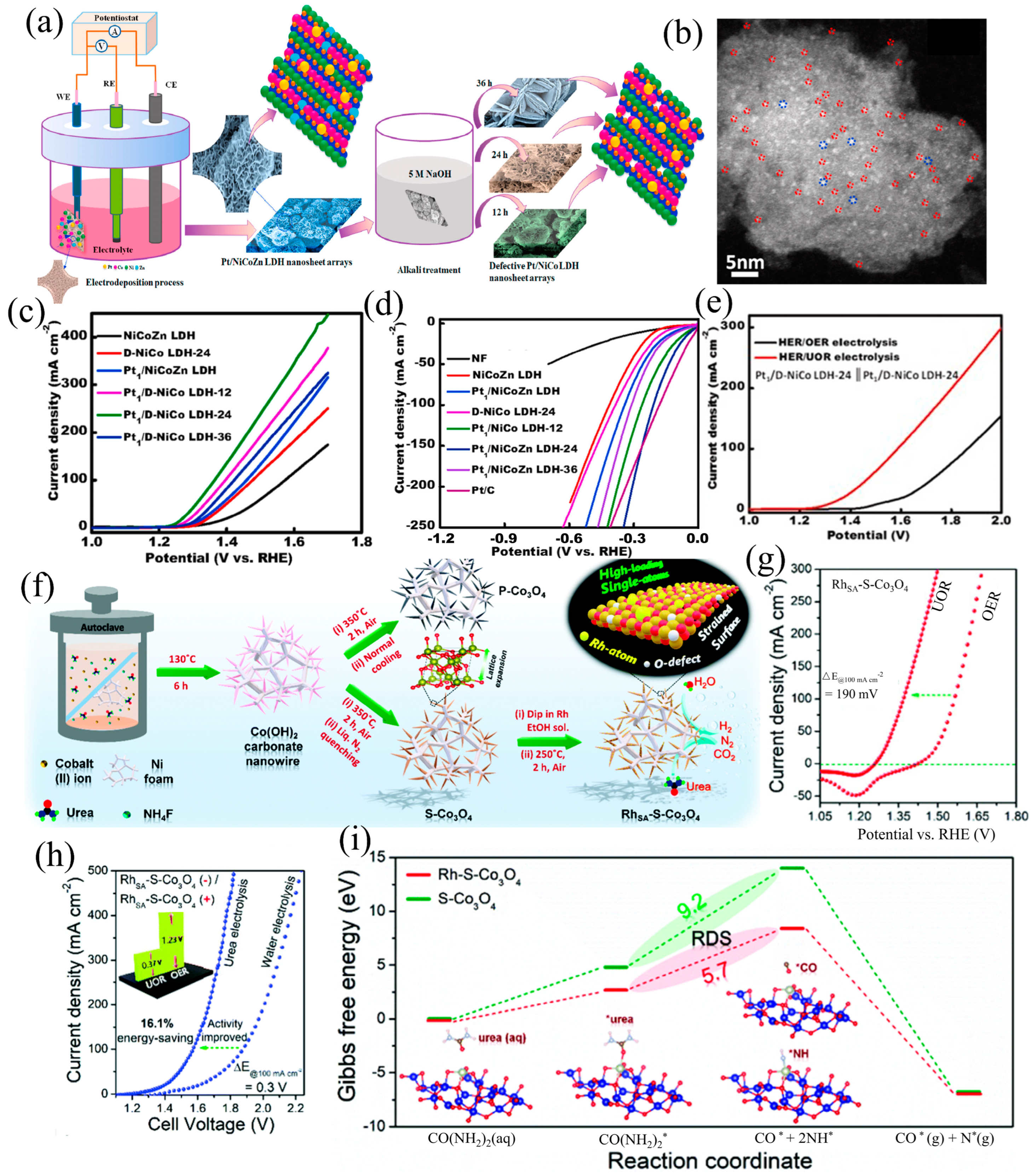
2.4. Single-Atom Design

Single-atom catalysts (SACs) have represented a novel field in catalytic science in recent years. Compared with traditional heterogeneous catalysts, SACs exhibit the highest atomic efficiency and unique physicochemical properties, local coordination, and electronic configurations. SACs can reduce the loading of precious metals and demonstrate excellent catalytic activity in various catalytic reactions. As a powerful analytical technique, X-ray absorption spectroscopy (XAS) not only provides more accurate information than XPS but also possesses unique advantages in studying the local structure, chemical state, and electronic properties of materials. Through XAS analysis, various defects such as vacancies, interstitial atoms, and lattice distortions can be accurately identified and quantified. This renders XAS an indispensable tool for investigating defects in various catalysts, thereby offering crucial support for gaining a deeper understanding of the defective structure of materials and its impact on catalytic activity.
Zhang et al. [79] synthesized AC-Co2(OH)3Cl-V-n catalysts doped with single-atom V through a process involving propylene oxide-induced hydrolysis to form the precatalyst, followed by electrochemical reconstruction. Afterward, X-ray absorption fine-structure (XAFS) spectroscopy was applied to ascertain the exact V structure within the AC-Co2(OH)3Cl-V-n samples. Firstly, V K-edge XANES spectra of the AC-Co2(OH)3Cl-V-n samples were obtained (Figure 7a). The results indicated that the spectra of these samples differed in shape from those of V foil and V2O3, indicating unique arrangements in the local geometry. Additionally, the AC-Co2(OH)3Cl-V-n series exhibited higher absorption edges compared to V foil and V2O3. This result suggests that V attained a high valence state following voltage-induced reconstruction (Figure 7b). To further explore the electronic structure surrounding the V atoms, an analysis using Fourier Transform Extended XAFS (FT-EXAFS) was performed. In the R-space spectra, the AC-Co2(OH)3Cl-V-n samples showed a dominant peak positioned at 1.32 Å. This observation further validates that V is in a single-atom configuration (Figure 7c). Moreover, WT-EXAFS plots demonstrated that the local configuration of V within the AC-Co2(OH)3Cl-V-0.1 sample was regulated (Figure 7d). In summary, the XAFS characterization provided strong evidence for the presence of V atoms in a single-atom form.
Besides V single atoms, other single-atom catalysts can also be detected using XAS. Chen et al. [73] synthesized an Ir-NiFe-OH catalyst by growing a NiCrOx precursor on NF via hydrothermal methods, followed by hydrogenation of the NiCrOx precursor in a reducing environment. They employed XAS to conduct a detailed characterization of the Ir-NiFe-OH catalyst. The results indicated that the average oxidation state of Ir atoms in Ir-NiFe-OH ranges between 0 and +4. Subsequent EXAFS analysis demonstrated that the Ir-Ir peak, corresponding to 2.6 Å in the Ir powder standard, is absent in Ir-NiFe-OH, further confirming that the Ir atoms in Ir-NiFe-OH are in a state of isolated dispersion. In Ir-NiFe-OH, the coordination number of the Ir-O shell was determined to be 3.9, suggesting that Ir atoms are coordinated with only a few O atoms in the support. Therefore, XAS characterization confirmed that Ir atoms in Ir-NiFe-OH exist in a single-atom form.
Khalafallah et al. [51] utilized an electrochemical deposition method paired with alkali etching to position Pt atoms on amorphous NiCo LDH nanosheet arrays that were generated in situ (denoted as Pt1/D-NiCo LDH-24 SAC) (Figure 8a). Aberration-corrected transmission electron microscopy demonstrated that the nanoscale defects introduced by etching significantly strengthened the interaction between individual Pt atoms and the LDH substrate (Figure 8b). This led to the development of a robust hybrid bifunctional single-atom catalyst, effectively preventing the clustering of Pt active sites down to the atomic scale. The Pt1/D-NiCo LDH-24 SAC exhibited outstanding HER and UOR performances, attaining 10 mA cm−2, requiring voltages of just 37 mV and 1.25 V. (vs. RHE), respectively (Figure 8c,d). Using a Pt1/D-NiCo LDH-24||Pt1/D-NiCo LDH-24 configuration for the electrolytic cell, the urea electrolyzer exhibited outstanding performance in the electrolysis tests, achieving 10 mA cm−2 at 1.32 V, which is 0.3 V lower than that required for pure water electrolysis (Figure 8e). They attribute the enhanced activity and longevity of the electrocatalyst to multiple factors, such as (i) 3D layered porous framework, composed of 2D nanosheets, which provides numerous accessible active sites. Additionally, it minimizes the aggregation tendency of Pt single atoms during catalytic reactions. (ii) Isolated atoms generally possess a precisely adjustable coordination environment and exhibit excellent structural uniformity. These atoms feature uniformly coordinated active centers composed of metals and support materials. The optimized LDH matrix, containing an appropriate concentration of Pt single atoms, enhances the surface distribution of active single atoms on the support material, increasing their overall density. (iii) Boosting electrocatalytic activity hinges on a substantial count of stable active catalytic sites. (iv) Defect engineering strengthens electron bonding, promoting the formation of active NiOOH sites and accelerating the electrochemical reaction process. Apart from Pt single atoms, there has been widespread research interest in other noble metal-based single-atom catalysts as well. Kumar et al. [52] utilized liquid nitrogen to achieve an ultrahigh cooling rate, enabling the sample to maintain its morphology, crystal phase, and elemental composition while expanding the unit cell lattice parameters (Figure 8f). This expansion caused tensile strain on the Co3O4 support surface, greatly reducing the tendency of Rh single atoms (RhSA) to migrate and thereby stabilizing their placement. The resulting RhSA-S-Co3O4/NF exhibited exceptional UOR activity, achieving 10 mA cm−2 at 1.28 V in KOH, surpassing Pt/Rh-C (Figure 8g). Furthermore, the urea electrolyzer assembled with dual-functional RhSA-S-Co3O4/NF operated at 1.33 V, achieving and maintaining 10 mA cm−2 for 120 h. (Figure 8h). According to DFT analysis, RhSA plays a crucial role in stabilizing CO* and NH* intermediates, thereby enhancing the adsorption and activation of urea molecules and improving the sluggish UOR kinetics (Figure 8i). Furthermore, the treated support surface hinders the movement of Rh single atoms, thereby preventing the aggregation of noble metals. Therefore, RhSA-S-Co3O4/NF exhibits outstanding UOR activity.

2.5. Other Defects

In addition to the previously listed defects, many types of lattice defects (such as lattice dislocations, expansions, and distortions) can also significantly alter the physicochemical properties of oxides. Numerous studies have reported the positive effects of these lattice defects in enhancing electrocatalytic performance. These defects not only enhance the conductivity of materials but also offer more sites for electrochemical reactions [80,81,82,83]. Huo et al. [53] synthesized M-FeNi LDH for UORs using a simple one-pot self-template strategy (Figure 9a). In the presence of Ni2+, high-valence metal ions were introduced to form trimetallic M-FeNi LDH. The high-valence metal ions, with their larger atomic radii compared to Fe/Ni in FeNi-LDH, caused lattice expansion. HRTEM revealed that Mo-FeNi had a lattice fringe spacing of 0.2 nm, consistent with the (110) plane of FeNi, but significantly larger than the 0.15 nm spacing of undoped FeNi. Meanwhile, V-FeNi and Mn-FeNi exhibited lattice fringe spacings of 0.18 nm and 0.17 nm, respectively, corresponding to the atomic radii of the high-valence metals—1.46 Å for Mo, 1.44 Å for V, and 1.29 Å for Mn—indicating lattice expansion after Mo doping (Figure 9b,c). Electrochemical tests indicated that Mo-doped FeNi had superior electrochemical activity, achieving 1.32 V at 10 mA cm−2, which is lower than the potentials required by V-FeNi (1.39 V) and Mn-FeNi (1.37 V) at the same current density (Figure 9d). Efficient H2 production was achieved using Mo-FeNi and Pt/C in urea-assisted dual-electrode water electrolysis. The results showed that using Pt/C||Mo-FeNi significantly reduced the hydrogen evolution voltage to 1.38 V at 10 mA cm−2 in an alkaline solution containing urea, which was much lower than the 1.49 V required for traditional water electrolysis at the same current density (Figure 9e). These results indicate that lattice expansion, caused by the high valence and large atomic size of the metals, optimizes the electronic structure. This enhancement improves performance in urea oxidation reactions and promotes urea-assisted water splitting for H2 production. Jin et al. [54] prepared a versatile Ru-NiO/p-Ni catalyst by doping with a small amount of Ru and annealing Ni(OH)2 nanosheets that were grown in situ on the surface of ordered porous Ni (Figure 9f). XRD analysis revealed that the NiO diffraction peak of Ru-NiO/p-Ni shifted to a smaller angle by 0.13° compared to Ru-p-Ni (Figure 9g), indicating unit cell volume expansion, which suggests lattice distortion. Electrochemical measurements showed that Ru-NiO/p-Ni could achieve 100 mA cm−2 at 1.39 V in 1.0 M KOH with 0.33 M urea, demonstrating efficient UOR activity (Figure 9h). Furthermore, using a Ru-NiO/p-Ni||Ru-NiO/p-Ni configuration for the electrolytic cell, a current density of 100 mA cm−2 was achieved during urea-assisted water splitting with only 1.58 V, representing 170 mV reduction compared to the 1.75 V required for pure water electrolysis (Figure 9h). Introducing urea-rich wastewater into the alkaline electrolyte and employing a UOR instead of the OER established a system for H2 production that is energy-efficient and demonstrates high H2 production activity. In Ru-NiO/p-Ni, the increased amount of high-valence nickel induced by ruthenium provided sufficient active sites, effectively enhancing the UOR kinetics and thus promoting H2 generation.
High-index facets (HIFs) typically have a higher density of low-coordination atoms and structural features such as atomic steps, kinks, and edges. During the preparation of catalysts, researchers control the reaction conditions to expose more of these specific facets, usually high-index facets. Those atoms on HIFs have fewer coordination atoms compared to those on low-index facets, resulting in higher surface energy and a greater propensity to interact with reactants, thereby reducing side reactions. The high density of steps, kinks, and edges provides more active sites for reactants. Additionally, high-index facets generally have higher surface energy, making them more active during catalysis. Currently, research on high-index facets is primarily focused on water electrolysis, with relatively few studies on their application in the UOR. Deng et al. [55] reported a simple low-temperature sulfuration strategy, wherein Ni3S2 nanosheet branches were grown on an atomic layer deposition TiO2 framework to synthesize TiO2@Ni3S2 core/branch arrays (Figure 10a). These arrays were used as binder-free electrodes in alkaline solution water-splitting electrolyzers. The core/branch array framework highlights a substantial active surface area, alongside a consistent porous structure, and the exposure of abundant (210) high-index facet active sites within the Ni3S2 nanosheets. Additionally, an angle of approximately 70° is observed between the (003) and (021) planes, aligning closely with the theoretical 70.8° (Figure 10b,c). This suggests that the (210) high-index facet is the exposed surface of the Ni3S2 nanosheets. Therefore, in alkaline media, the TiO2@Ni3S2 core/branch arrays exhibited significant electrocatalytic activity. Specifically, at 10 mA cm−2, the overpotentials were 220 mV for the OER and 112 mV for the HER (vs. RHE), respectively (Figure 10d,e). The TiO2@Ni3S2 electrode demonstrates outstanding catalytic activity for the OER and HER. Testing it as both the cathode and anode in overall water electrolysis revealed 10 mA cm−2 at 1.58 V (Figure 10f). These electrochemical performance tests indicate that the designed TiO2@Ni3S2 core/branch arrays possess excellent electrocatalytic properties, making them promising candidates for practical alkaline water-splitting applications. Compared to traditional TiO2 nanowire array structures (NWAs), TiO2 nanopyramid arrays (NPAs) were synthesized through the modulation of F- ion concentration in the growth medium (Figure 10g) by Li et al. [56]. Unlike NWAs, NPAs expose more (001) facets. The (001) facets have higher surface energy and more low-coordination active sites, providing stronger adsorption sites for Ni nanoparticles. Subsequently, they used atomic layer deposition to grow Ni3S2 nanosheet branches on the TiO2 framework, constructing TiO2@Ni3S2 core/branch arrays. This method retains the activity of the TiO2 high-index facets while optimizing catalytic activity through Ni3S2 incorporation. The authors used HRTEM to observe the lattice fringes on the top and side walls of the TiO2 NPAs. The HRTEM image in Figure 10h shows lattice spacings matching the (001) facets, confirming the presence of (001) facets. The corresponding SAED pattern (Figure 10i) shows clear and orderly diffraction spots, indicative of a typical single-crystal structure. The specific arrangement and symmetry of the diffraction spots correspond to the (001) facets of anatase TiO2, further confirming the presence and dominance of the (001) facets. Additionally, SEM images demonstrate the pyramid morphology of the TiO2 NPAs, with side-view SEM images clearly showing four isosceles trapezoidal sidewalls and a flat top surface in each nanostructure (Figure 10j). HER activity tests also showed that TiO2 nanopyramid arrays have better performance compared to TiO2 nanowire array structures. Ni/TiO2 NPAs exhibit a low overpotential of 88 mV at 10 mA cm−2. In contrast, TiO2 NPAs achieve 10 mA cm−2 at a higher overpotential of 418 mV (Figure 10k). However, to date, there have been few reports on the application of HIFs in UORs. Therefore, more theoretical calculations and experimental studies are needed to explore efficient UOR electrocatalysts with HIFs.
In addition to various defect types mentioned previously, the choice of a suitable substrate is crucial for enhancing UOR activity. Among the many substrates, nickel foam has garnered the most attention. Tu et al. [84] immersed nickel foam in a solution containing thiourea and I2/KI, forming a new active layer on the surface of the nickel foam through chemical etching. In this process, NF serves not only as a substrate but also as a nickel source, playing an important structural and functional role. Additionally, its inherent fluffy nanosheet structure exposes more active sites, thereby enhancing UOR activity. He et al. [85] treated nickel foam more simply by directly oxidizing it at low temperatures to form amorphous NiO nanoclusters with a high defect concentration. The high defect concentration in amorphous NiO nanoclusters provides more active sites. Studies have shown that the high defect concentration in NF, including vacancies and dislocations, enhances its catalytic activity. These defects act as active sites, improving the adsorption and interaction of reactants, thereby increasing overall electrocatalytic performance. For example, defects in nickel foam are associated with improved performance in hydrogen evolution reactions due to increased active site availability and enhanced electron transfer capabilities. Moreover, the inherent properties of NF make it durable in alkaline environments, which is beneficial for processes such as the UOR. Using nickel foam in UORs not only leverages its structural advantages but also provides a direct source of nickel.

3. Conclusions and Outlook

This paper reviews the application of defect engineering in nickel-based compounds for the UOR, aiming to replace the OER with the UOR to achieve energy-saving H2 production. Various synthesis strategies can introduce specific types and concentrations of defects in electrocatalysts, including heteroatom doping, vacancy creation, amorphization, single-atom catalysts, and high-index facets. These strategies significantly affect the electronic structure, surface properties, and catalytic activity of nickel-based compounds, thereby enhancing their performance in energy-efficient hydrogen production. Furthermore, we have introduced advanced characterization techniques for defect confirmation, which supports better a understanding of the nature of defects. For example, these techniques include HRTEM for visualizing atomic-scale defects, XPS for analyzing surface chemical states, XAFS for probing local structural changes, and Raman spectroscopy for detecting vibrational modes of defect states. These methods provide multifaceted insights into how defects influence the catalytic activity of nickel-based compounds. Despite significant progress in defective engineering of electrocatalysts, several key challenges lie ahead.
(i) The controllable synthesis of catalysts: Currently, most catalysts possess multiple types of defects, rather than a single defect type tailored for specific reactions. This multiplicity makes it difficult to elucidate the relationship between defects and catalyst performance. If synthesis strategies could be improved to control the type and concentration of defects, it would not only facilitate the study of the impact of defects on performance but also enhance performance while minimizing side reactions.
(ii) The application of defect engineering in the UOR: While previously mentioned defect engineering strategies (such as amorphization, single-atom catalysts, and heteroatom doping) have been applied in UORs, the strategy of utilizing high-index facets in UORs is scarcely explored, primarily due to the difficulty in synthesizing HIF materials. In future, the application of HIF materials in water electrolysis can be leveraged and further developed for urea electrolysis reactions.
(iii) Defect engineering in catalysts aims to enhance their performance by disrupting the catalyst’s original structure. However, this process also renders the catalyst itself unstable. Therefore, functionalizing the catalyst is necessary to improve performance while enhancing its stability. Feasible methods include inducing partial amorphization or employing heteroatoms to fill the defects.
(iv) The need for more precise and advanced in situ characterization techniques: Current characterization methods are often indirect and lack precision when describing the local coordination environment of defects. Advanced techniques are required to explore the evolution of catalyst defects during urea oxidation processes, thereby deepening our understanding and laying the foundation for future practical applications.
(v) The cost of catalyst preparation: Large-scale efficient production of defect-engineered electrocatalysts remains impractical at present. Despite the promising prospects of defect engineering in catalyst modification, current research in defect engineering of catalysts remains at the laboratory scale and has not yet transitioned to industrial applications. Therefore, reducing catalyst costs and simplifying preparation processes are crucial for achieving industrial applications of defect-engineered electrocatalysts.

Author Contributions

Conceptualization, S.L. and X.Q.; methodology, Y.Z.; software, X.D.; investigation, Y.Z.; resources, M.N.K.; writing—original draft preparation, Y.Z. and M.N.K.; writing—review and editing, S.L., X.Q. and H.W.; visualization, X.D.; supervision, S.L.; funding acquisition, X.D. and H.W. All authors have read and agreed to the published version of the manuscript.

Funding

This research was funded by the Natural Science Foundation of Chongqing (2023NSCQ-MSX1669), the Radiation Reform and Development Special Project—Development of Superhard Yet Tough Coatings (No. 24CB007-03), and the Priority Academic Program Development of Jiangsu Higher Education Institutions (PAPD-2023-87).

Conflicts of Interest

The authors declare no conflicts of interest.

References

  1. Huber, G.W.; Shabaker, J.W.; Dumesic, J.A. Raney Ni-Sn Catalyst for H2 Production from Biomass-Derived Hydrocarbons. Science 2003, 300, 2075–2077. [Google Scholar] [CrossRef] [PubMed]
  2. Wang, G.; Ling, Y.; Lu, X.; Wang, H.; Qian, F.; Tong, Y.; Li, Y. Solar Driven Hydrogen Releasing from Urea and Human Urine. Energy Environ. Sci. 2012, 5, 8215–8219. [Google Scholar] [CrossRef]
  3. Yang, X.; Lu, A.-Y.; Zhu, Y.; Hedhili, M.N.; Min, S.; Huang, K.-W.; Han, Y.; Li, L.-J. CoP Nanosheet Assembly Grown on Carbon Cloth: A Highly Efficient Electrocatalyst for Hydrogen Generation. Nano Energy 2015, 15, 634–641. [Google Scholar] [CrossRef]
  4. Yu, H.; Qi, L.; Hu, Y.; Qu, Y.; Yan, P.; Isimjan, T.T.; Yang, X. Nanowire-Structured FeP-CoP Arrays as Highly Active and Stable Bifunctional Electrocatalyst Synergistically Promoting High-Current Overall Water Splitting. J. Colloid Interface Sci. 2021, 600, 811–819. [Google Scholar] [CrossRef] [PubMed]
  5. Gan, Q.; Cheng, X.; Chen, J.; Wang, D.; Wang, B.; Tian, J.; Isimjan, T.T.; Yang, X. Temperature Effect on Crystallinity and Chemical States of Nickel Hydroxide as Alternative Superior Catalyst for Urea Electrooxidation. Electrochim. Acta 2019, 301, 47–54. [Google Scholar] [CrossRef]
  6. Li, Y.; Wei, X.; Chen, L.; Shi, J. Electrocatalytic Hydrogen Production Trilogy. Angew. Chem. Int. Ed. 2021, 60, 19550–19571. [Google Scholar] [CrossRef] [PubMed]
  7. Zhang, M.; Zhou, W.; Yan, X.; Huang, X.; Wu, S.; Pan, J.; Shahnavaz, Z.; Li, T.; Yu, X. Sodium dodecyl sulfate intercalated two-dimensional nickel-cobalt layered double hydroxides to synthesize multifunctional nanomaterials for supercapacitors and electrocatalytic hydrogen evolution. Fuel 2023, 333, 126323. [Google Scholar] [CrossRef]
  8. Li, J.; Wang, S.; Chang, J.; Feng, L. A Review of Ni Based Powder Catalyst for Urea Oxidation in Assisting Water Splitting Reaction. Adv. Powder Mater. 2022, 1, 100030. [Google Scholar] [CrossRef]
  9. Sun, X.; Ding, R. Recent Progress with Electrocatalysts for Urea Electrolysis in Alkaline Media for Energy-Saving Hydrogen Production. Catal. Sci. Technol. 2020, 10, 1567–1581. [Google Scholar] [CrossRef]
  10. Liu, Y.; Xing, Y.; Xu, S.; Lu, Y.; Sun, S.; Jiang, D. Interfacing Co3Mo with CoMoOx for synergistically boosting electrocatalytic hydrogen and oxygen evolution reactions. Chem. Eng. J. 2022, 431, 144660. [Google Scholar] [CrossRef]
  11. Xu, X.; Shao, Z.; Jiang, S.P. High-entropy Materials for Water Electrolysis. Energy Technol. 2022, 10, 2200573. [Google Scholar] [CrossRef]
  12. She, S.; Zhu, Y.; Wu, X.; Hu, Z.; Shelke, A.; Pong, W.-F.; Chen, Y.; Song, Y.; Liang, M.; Chen, C.-T. Realizing High and Stable Electrocatalytic Oxygen Evolution for Iron-based Perovskites by Co-doping-induced Structural and Electronic Modulation. Adv. Funct. Mater. 2022, 32, 2111091. [Google Scholar] [CrossRef]
  13. Lu, S.; Wang, Q.; Fang, L.; Zheng, X.; Yin, F.; Liu, H. Bimetallic Platinum-Nickel Nanoparticles Modified on the Screen-Printed Electrode for Highly Sensitive Urea Determination. IEEE Sens. J. 2024, 24, 4221–4227. [Google Scholar] [CrossRef]
  14. Yao, Z.-C.; Tang, T.; Jiang, Z.; Wang, L.; Hu, J.-S.; Wan, L.-J. Electrocatalytic Hydrogen Oxidation in Alkaline Media: From Mechanistic Insights to Catalyst Design. ACS Nano 2022, 16, 5153–5183. [Google Scholar] [PubMed]
  15. Ji, Q.; Yu, X.; Chen, L.; Okonkwo, C.E.; Zhou, C. Effect of cobalt doping and sugarcane bagasse carbon on the electrocatalytic performance of MoS2 nanocomposites. Fuel 2022, 324, 124814. [Google Scholar] [CrossRef]
  16. Lu, S.; Hummel, M.; Gu, Z.; Wang, Y.; Wang, K.; Pathak, R.; Zhou, Y.; Jia, H.; Qi, X.; Zhao, X.; et al. Highly efficient urea oxidation via nesting nano-nickel oxide in eggshell membrane-derived carbon. ACS Sustain. Chem. Eng. 2021, 9, 1703–1713. [Google Scholar]
  17. Zhang, Z.; Li, L.; Li, Y.; Zheng, Y.; Wu, Q.; Xie, L.; Luo, B.; Hao, J.; Shi, W. Activating MoO4 tetrahedrons to MoOx species in MoNi alloy for boosting performance in alkaline hydrogen evolution reaction. Chem. Eng. J. 2023, 469, 143846. [Google Scholar]
  18. Zheng, X.; Lu, S. Theoretical Exploration of Anchoring Type Effects of C2N Nanosheet-Supported Nickel Atoms for Urea Electrooxidation. ACS Appl. Nano Mater. 2024, 7, 3361–3372. [Google Scholar] [CrossRef]
  19. Wang, Q.; Liu, J.; Li, T.; Zhang, T.; Arbiol, J.; Yan, S.; Wang, Y.; Li, H.; Cabot, A. Pd2Ga nanorods as highly active bifunctional catalysts for electrosynthesis of acetic acid coupled with hydrogen production. Chem. Eng. J. 2022, 446, 136878. [Google Scholar] [CrossRef]
  20. Wang, H.; Zheng, X.; Fang, L.; Lu, S. Urea electrooxidation in alkaline environment: Fundamentals and applications. ChemElectroChem 2023, 10, e202300138. [Google Scholar] [CrossRef]
  21. Peng, X.; Wang, T.; Liu, B.; Li, Y.; Zhao, T. A Solvent Molecule Reconstruction Strategy Enabling a High-Voltage Ether-Based Electrolyte. Energy Environ. Sci. 2022, 15, 5350–5361. [Google Scholar] [CrossRef]
  22. Lu, S.; Zheng, X.; Fang, L.; Yin, F.; Liu, H. Rational engineering design of nickel hydroxides for urea oxidation reaction: A mini-review. Electrochem. Commun. 2023, 157, 107599. [Google Scholar] [CrossRef]
  23. Wang, H.; Guo, Y.; Mao, Q.; Yu, H.; Deng, K.; Wang, Z.; Li, X.; Xu, Y.; Wang, L. Sulfur and Phosphorus Co-Doping Optimized Electronic Structure and Modulated Intermediate Affinity on PdSP Metallene for Ethanol-Assisted Energy-Saving H2 Production. Nanoscale 2023, 15, 7765–7771. [Google Scholar] [CrossRef]
  24. Meng, N.; Ma, X.; Wang, C.; Wang, Y.; Yang, R.; Shao, J.; Huang, Y.; Xu, Y.; Zhang, B.; Yu, Y. Oxide-Derived Core–Shell Cu@ Zn Nanowires for Urea Electrosynthesis from Carbon Dioxide and Nitrate in Water. ACS Nano 2022, 16, 9095–9104. [Google Scholar] [CrossRef]
  25. Lu, S.; Zheng, X.; Wang, H.; Wang, C.; Akinlabi, E.; Xu, B.; Yang, X.; Hua, Q.; Liu, H. Energy-saving hydrogen production by heteroatom modulations coupling urea electrooxidation. EcoMat 2024, e12477. [Google Scholar] [CrossRef]
  26. Boggs, B.K.; King, R.L.; Botte, G.G. Urea Electrolysis: Direct Hydrogen Production from Urine. Chem. Commun. 2009, 4859–4861. [Google Scholar] [CrossRef] [PubMed]
  27. Lan, R.; Tao, S.; Irvine, J.T. A Direct Urea Fuel Cell–Power from Fertiliser and Waste. Energy Environ. Sci. 2010, 3, 438–441. [Google Scholar] [CrossRef]
  28. Xu, W.; Wu, Z.; Tao, S. Urea-based Fuel Cells and Electrocatalysts for Urea Oxidation. Energy Technol. 2016, 4, 1329–1337. [Google Scholar] [CrossRef]
  29. Liao, W.; Zhao, Q.; Wang, S.; Ran, Y.; Su, H.; Gan, R.; Lu, S.; Zhang, Y. Insights into mechanisms on electrochemical oxygen evolution substitution reactions. J. Catal. 2023, 428, 115161. [Google Scholar] [CrossRef]
  30. Chakrabarty, S.; Offen-Polak, I.; Burshtein, T.Y.; Farber, E.M.; Kornblum, L.; Eisenberg, D. Urea Oxidation Electrocatalysis on Nickel Hydroxide: The Role of Disorder. J. Solid State Electrochem. 2021, 25, 159–171. [Google Scholar] [CrossRef]
  31. Urbańczyk, E.; Sowa, M.; Simka, W. Urea Removal from Aqueous Solutions—A Review. J. Appl. Electrochem. 2016, 46, 1011–1029. [Google Scholar] [CrossRef]
  32. Zhang, J.; Liu, X.; Ji, Y.; Liu, X.; Su, D.; Zhuang, Z.; Chang, Y.-C.; Pao, C.-W.; Shao, Q.; Hu, Z. Atomic-Thick Metastable Phase RhMo Nanosheets for Hydrogen Oxidation Catalysis. Nat. Commun. 2023, 14, 1761. [Google Scholar] [CrossRef] [PubMed]
  33. Zheng, X.; Zhang, L.; He, W.; Li, L.; Lu, S. Heteroatom-doped nickel sulfide for efficient electrochemical oxygen evolution reaction. Energies 2023, 16, 881. [Google Scholar] [CrossRef]
  34. Wang, L.; Zhang, L.; Ma, W.; Wan, H.; Zhang, X.; Zhang, X.; Jiang, S.; Zheng, J.; Zhou, Z. In Situ Anchoring Massive Isolated Pt Atoms at Cationic Vacancies of α-NixFe1-x(OH)2 to Regulate the Electronic Structure for Overall Water Splitting. Adv. Funct. Mater. 2022, 32, 2203342. [Google Scholar] [CrossRef]
  35. Li, L.; Lu, S.; Dai, Y.; Li, H.; Wang, X.; Zhang, Y. Controlled synthesis of hierarchical nanostructured metal ferrite microspheres for enhanced electrocatalytic oxygen evolution reaction. ACS Appl. Nano Mater. 2023, 6, 2184–2192. [Google Scholar] [CrossRef]
  36. Wu, Z.; Guo, X.; Zhang, Z.; Song, M.; Jiao, T.; Zhu, Y.; Wang, J.; Liu, X. Interface Engineering of MoS2 for Electrocatalytic Performance Optimization for Hydrogen Generation via Urea Electrolysis. ACS Sustain. Chem. Eng. 2019, 7, 16577–16584. [Google Scholar] [CrossRef]
  37. Zeng, Y.; Xiang, S.; Lu, S.; Qi, X. Structural Design of Nickel Hydroxide for Efficient Urea Electrooxidation. Materials 2024, 17, 2617. [Google Scholar] [CrossRef] [PubMed]
  38. Lu, S.; Gu, Z.; Hummel, M.; Zhou, Y.; Wang, K.; Xu, B.B.; Wang, Y.; Li, Y.; Qi, X.; Liu, X. Nickel Oxide Immobilized on the Carbonized Eggshell Membrane for Electrochemical Detection of Urea. J. Electrochem. Soc. 2020, 167, 106509. [Google Scholar] [CrossRef]
  39. Li, F.-M.; Xia, C.; Xia, B.Y. Exploration and Insight of Dynamic Structure Evolution for Electrocatalysts. Acc. Mater. Res. 2023, 4, 427–437. [Google Scholar] [CrossRef]
  40. He, F.; Zheng, Q.; Yang, X.; Wang, L.; Zhao, Z.; Xu, Y.; Hu, L.; Kuang, Y.; Yang, B.; Li, Z. Spin-State Modulation on Metal–Organic Frameworks for Electrocatalytic Oxygen Evolution. Adv. Mater. 2023, 35, 2304022. [Google Scholar] [CrossRef]
  41. Zhang, X.; Yin, X.; Song, Z.; Zhu, K.; Cao, D.; Yao, J.; Wang, G.; Yan, Q. Peony-like CuxSy Hybrid Iron-Nickel Sulfide Heterogeneous Catalyst for Boosting Alkaline Oxygen Evolution Reaction. Surf. Interfaces 2023, 38, 102788. [Google Scholar] [CrossRef]
  42. Zhang, X.; Xue, Y.; Yin, X.; Shen, L.; Zhu, K.; Huang, X.; Cao, D.; Yao, J.; Wang, G.; Yan, Q. Defect-Rich MnxOy Complex Fe–Ni Sulfide Heterogeneous Electrocatalyst for a Highly Efficient Hydrogen Evolution Reaction. J. Power Sources 2022, 540, 231664. [Google Scholar] [CrossRef]
  43. Zhang, X.; Song, Z.; Yan, Q.; Cong, W.; Yang, L.; Zhu, K.; Ye, K.; Yan, J.; Cao, D.; Wang, G. Tremella-like Manganese Dioxide Complex (Fe, Ni) 3S4 Hybrid Catalyst for Highly Efficient Oxygen Evolution Reaction. J. Power Sources 2021, 515, 230627. [Google Scholar] [CrossRef]
  44. Qiu, Y.; Dai, X.; Wang, Y.; Ji, X.; Ma, Z.; Liu, S. The Polyoxometalates Mediated Preparation of Phosphate-Modified NiMoO4− x with Abundant O-Vacancies for H2 Production via Urea Electrolysis. J. Colloid Interface Sci. 2023, 629, 297–309. [Google Scholar] [CrossRef] [PubMed]
  45. Xu, X.; Dong, Y.; Liu, F.; Wang, H.; Wang, X.; Li, X.; Ren, J.; Wang, R. The Ni–P Dual Vacancies Crystalline/Amorphous Bifunctional Electrode with ZnO “Electron Pump” for Urea-Assisted Electrolysis of Water to Produce Hydrogen. Int. J. Hydrogen Energy 2024, 49, 984–994. [Google Scholar] [CrossRef]
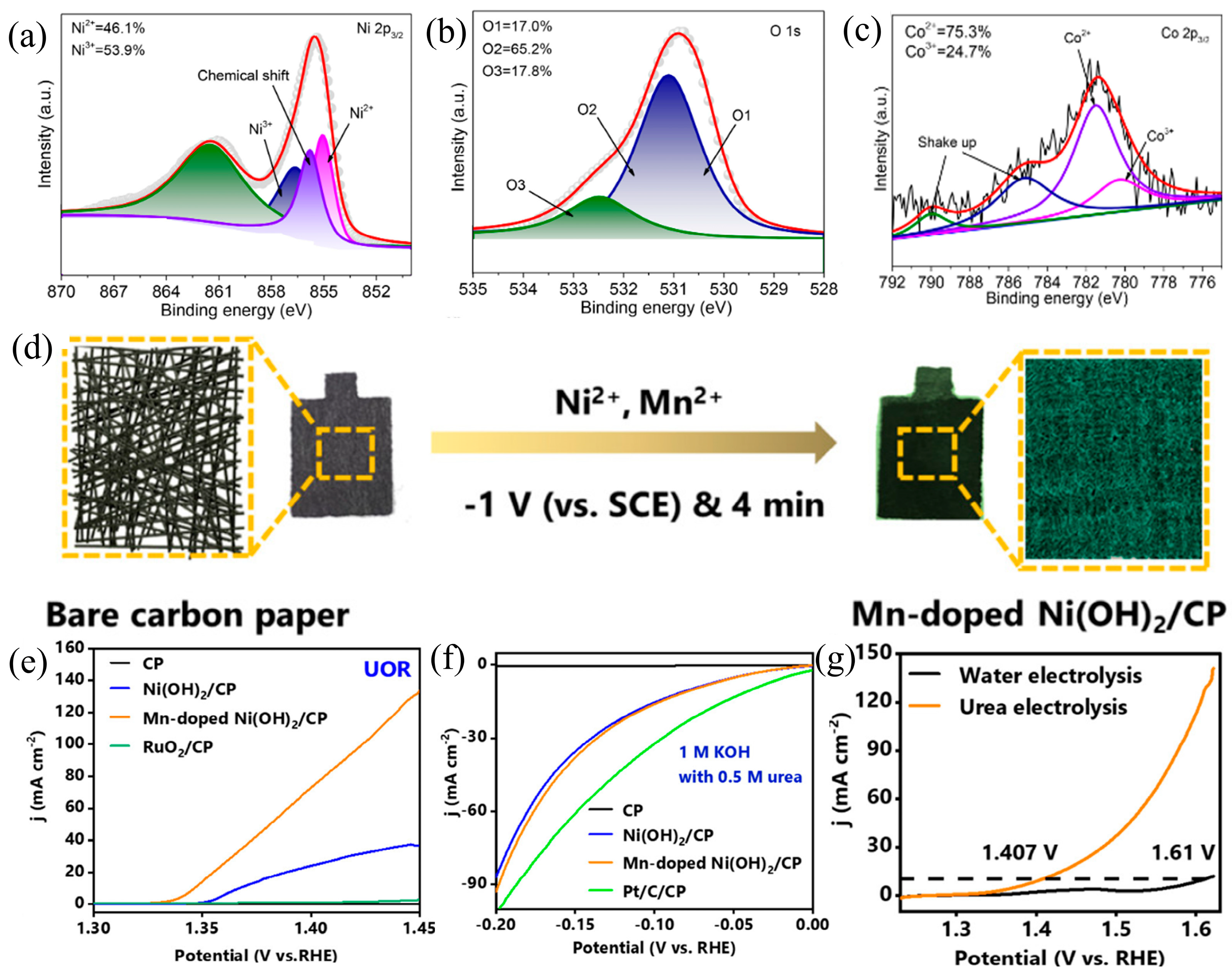
  46. Liu, X.; Qin, H.; Ye, Z.; Yao, D.; Miao, W.; Mao, S. Interconnected Mn-Doped Ni (OH) 2 Nanosheet Layer for Bifunctional Urea Oxidation and Hydrogen Evolution: The Relation between Current Drop and Urea Concentration during the Long-Term Operation. ACS EST Eng. 2022, 2, 853–862. [Google Scholar] [CrossRef]
  47. Yuan, W.; Jiang, T.; Fang, X.; Fan, Y.; Qian, S.; Gao, Y.; Cheng, N.; Xue, H.; Tian, J. Interface Engineering of S-Doped Co2P@ Ni2P Core–Shell Heterostructures for Efficient and Energy-Saving Water Splitting. Chem. Eng. J. 2022, 439, 135743. [Google Scholar] [CrossRef]
  48. Guo, L.; Chi, J.; Zhu, J.; Cui, T.; Lai, J.; Wang, L. Dual-Doping NiMoO4 with Multi-Channel Structure Enable Urea-Assisted Energy-Saving H2 Production at Large Current Density in Alkaline Seawater. Appl. Catal. B Environ. 2023, 320, 121977. [Google Scholar] [CrossRef]
  49. Chen, N.; Du, Y.-X.; Zhang, G.; Lu, W.-T.; Cao, F.-F. Amorphous Nickel Sulfoselenide for Efficient Electrochemical Urea-Assisted Hydrogen Production in Alkaline Media. Nano Energy 2021, 81, 105605. [Google Scholar] [CrossRef]
  50. Qiao, L.; Zhu, A.; Liu, D.; Feng, J.; Chen, Y.; Chen, M.; Zhou, P.; Yin, L.; Wu, R.; Ng, K.W. Crystalline Phosphides/Amorphous Oxides Composite for Energy-Saving Hydrogen Production Assisted by Efficient Urea Oxidation Reaction. Chem. Eng. J. 2023, 454, 140380. [Google Scholar] [CrossRef]
  51. Khalafallah, D.; Farghaly, A.A.; Ouyang, C.; Huang, W.; Hong, Z. Atomically Dispersed Pt Single Sites and Nanoengineered Structural Defects Enable a High Electrocatalytic Activity and Durability for Hydrogen Evolution Reaction and Overall Urea Electrolysis. J. Power Sources 2023, 558, 232563. [Google Scholar] [CrossRef]
  52. Kumar, A.; Liu, X.; Lee, J.; Debnath, B.; Jadhav, A.R.; Shao, X.; Bui, V.Q.; Hwang, Y.; Liu, Y.; Kim, M.G. Discovering Ultrahigh Loading of Single-Metal-Atoms via Surface Tensile-Strain for Unprecedented Urea Electrolysis. Energy Environ. Sci. 2021, 14, 6494–6505. [Google Scholar] [CrossRef]
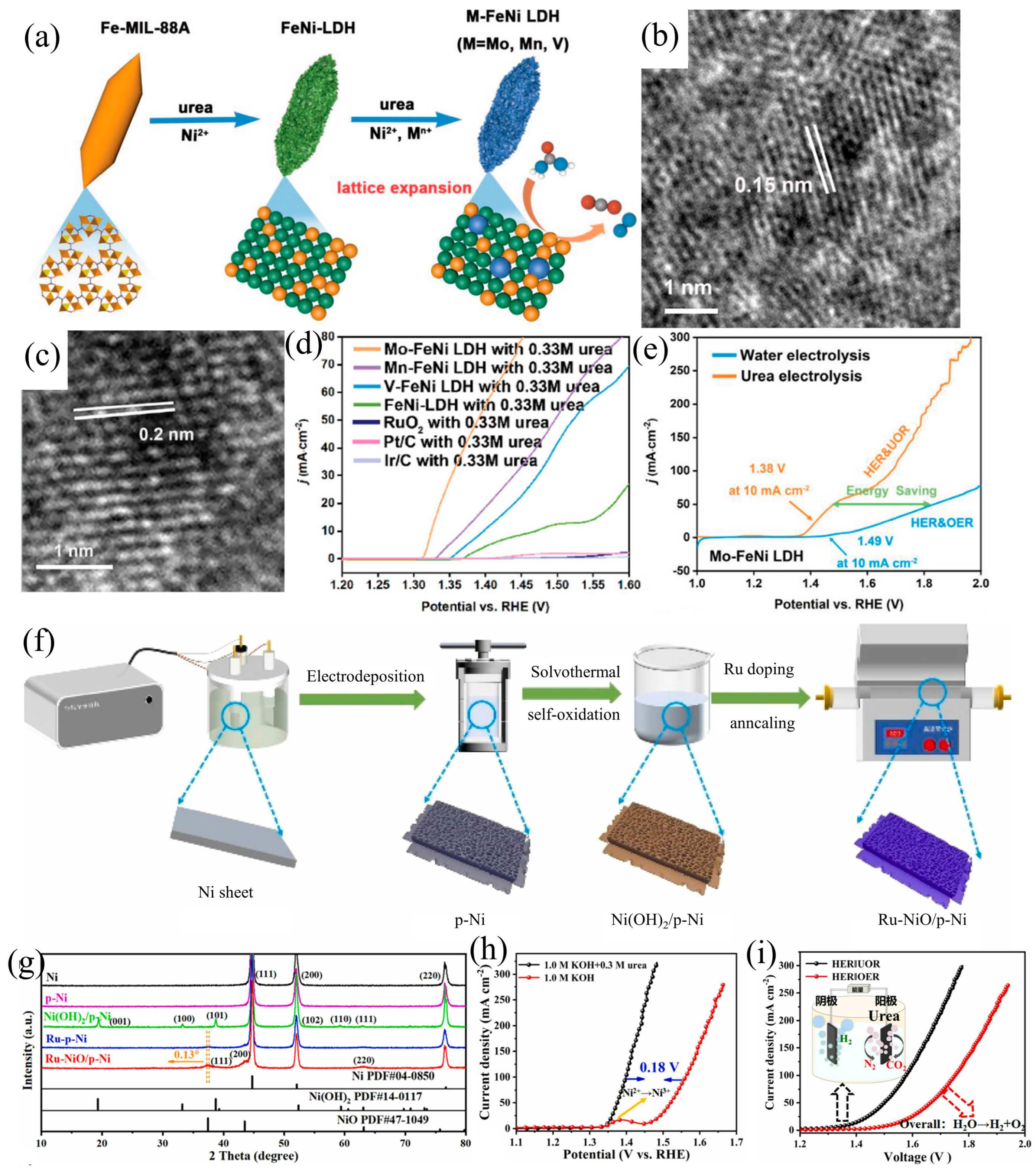
  53. Huo, J.-M.; Wang, Y.; Xue, J.-N.; Yuan, W.-Y.; Zhai, Q.-G.; Hu, M.-C.; Li, S.-N.; Chen, Y. High-Valence Metal Doping Induced Lattice Expansion for M-FeNi LDH toward Enhanced Urea Oxidation Electrocatalytic Activities. Small 2024, 20, 2305877. [Google Scholar] [CrossRef] [PubMed]
  54. Jin, H.; Yu, L.; Xiong, K.; Chen, J.; Zhang, H.; Deng, M.; Shi, X. An Energy-Efficient H2 Production Based on Urea-Aided Water Splitting Enhanced by Ru Induced in-Situ Speciation of NiO Nanosheets on Porous Ni. J. Alloys Compd. 2024, 983, 173938. [Google Scholar] [CrossRef]
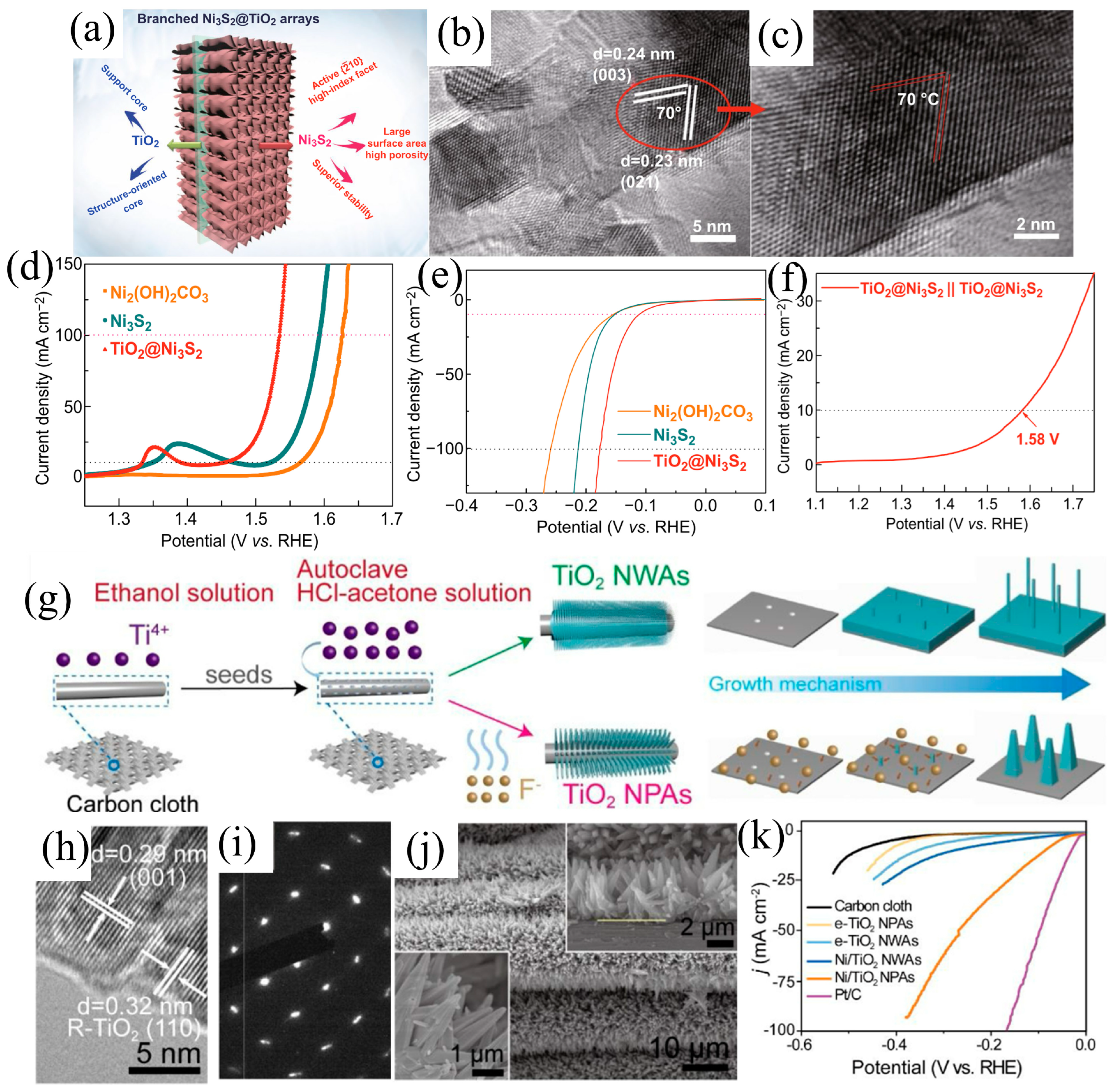
  55. Wu, J.; Wang, X.; Deng, S.; Zhang, K.; Xie, D.; Zhang, Y.; Zhang, Y.; Wang, Y.; Fan, H.J.; Xia, X. High-Index-Faceted Ni3S2 Branch Arrays as Bifunctional Electrocatalysts for Efficient Water Splitting. Nano-Micro Lett. 2019, 11, 12. [Google Scholar]
  56. Li, Y.; Min, K.-A.; Han, B.; Lee, L.Y.S. Ni Nanoparticles on Active (001) Facet-Exposed Rutile TiO2 Nanopyramid Arrays for Efficient Hydrogen Evolution. Appl. Catal. B Environ. 2021, 282, 119548. [Google Scholar] [CrossRef]
  57. Li, Y.; Luo, F.; Xie, Y.; Chang, C.; Xie, M.; Yang, Z. Oxygen Vacancies in α-Ni(OH)2 Porous Nanoflowers Promote Urea Oxidation. Int. J. Hydrogen Energy 2023, 48, 9155–9162. [Google Scholar] [CrossRef]
  58. Qin, H.; Ye, Y.; Li, J.; Jia, W.; Zheng, S.; Cao, X.; Lin, G.; Jiao, L. Synergistic Engineering of Doping and Vacancy in Ni(OH) 2 to Boost Urea Electrooxidation. Adv. Funct. Mater. 2023, 33, 2209698. [Google Scholar] [CrossRef]
  59. Zhang, K.; Duan, Y.; Graham, N.; Yu, W. Unveiling the Synergy of Polymorph Heterointerface and Sulfur Vacancy in NiS/Ni3S2 Electrocatalyst to Promote Alkaline Hydrogen Evolution Reaction. Appl. Catal. B Environ. 2023, 323, 122144. [Google Scholar]
  60. He, Q.; Wan, Y.; Jiang, H.; Pan, Z.; Wu, C.; Wang, M.; Wu, X.; Ye, B.; Ajayan, P.M.; Song, L. Nickel Vacancies Boost Reconstruction in Nickel Hydroxide Electrocatalyst. ACS Energy Lett. 2018, 3, 1373–1380. [Google Scholar] [CrossRef]
  61. Ye, Y.; Gan, Y.; Cai, R.; Dai, X.; Yin, X.; Nie, F.; Ren, Z.; Wu, B.; Cao, Y.; Zhang, X. Oxygen Vacancies and Surface Reconstruction on NiFe LDH@Ni(OH)2 Heterojunction Synergistically Triggering Oxygen Evolution and Urea Oxidation Reaction. J. Alloys Compd. 2022, 921, 166145. [Google Scholar] [CrossRef]
  62. Zhou, X.; Du, X.; Zhang, X. Controlled Synthesis of M Doped NiMoO4 (M = Co, Cu and Fe) for Urea, Freshwater and Seawater Oxidation Reaction. Fuel 2024, 371, 132050. [Google Scholar] [CrossRef]
  63. Zhang, Y.; Qiu, Y.; Wang, Y.; Li, B.; Zhang, Y.; Ma, Z.; Liu, S. Coaxial Ni–S@N-Doped Carbon Nanofibers Derived Hierarchical Electrodes for Efficient H 2 Production via Urea Electrolysis. ACS Appl. Mater. Interfaces 2021, 13, 3937–3948. [Google Scholar] [CrossRef] [PubMed]
  64. Gao, C.; Wei, G.; Wang, C.; Zhou, X.; Zhao, X.; Zhao, Q.; Wang, S.; Kong, F. In Situ Topologically Induced Metastable Phase Ni/r-Ni(OH)2@C Heterostructures with Abundant Oxygen Vacancies as Efficient Bifunctional Electrocatalysts for Energy-Saving Hydrogen Production. J. Alloys Compd. 2023, 959, 170545. [Google Scholar] [CrossRef]
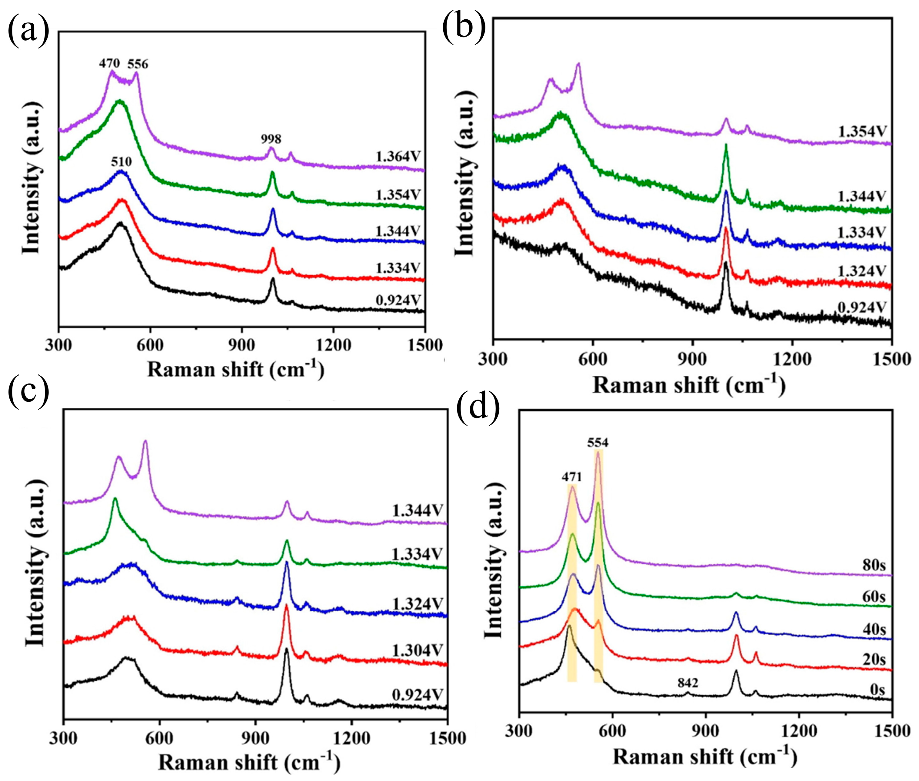
  65. Yang, X.; Zhang, H.; Xu, W.; Yu, B.; Liu, Y.; Wu, Z. A Doping Element Improving the Properties of Catalysis: In Situ Raman Spectroscopy Insights into Mn-Doped NiMn Layered Double Hydroxide for the Urea Oxidation Reaction. Catal. Sci. Technol. 2022, 12, 4471–4485. [Google Scholar] [CrossRef]
  66. Jin, L.; Ji, R.; Wan, H.; He, J.; Gu, P.; Lin, H.; Xu, Q.; Lu, J. Boosting the Electrocatalytic Urea Oxidation Performance by Amorphous–Crystalline Ni-TPA@ NiSe Heterostructures and Mechanism Discovery. ACS Catal. 2022, 13, 837–847. [Google Scholar] [CrossRef]
  67. Dong, Z.; Lin, F.; Yao, Y.; Jiao, L. Crystalline Ni (OH) 2/Amorphous NiMoOx Mixed-catalyst with Pt-like Performance for Hydrogen Production. Adv. Energy Mater. 2019, 9, 1902703. [Google Scholar] [CrossRef]
  68. Jia, X.; Kang, H.; Yang, X.; Li, Y.; Cui, K.; Wu, X.; Qin, W.; Wu, G. Amorphous Ni(III)-Based Sulfides as Bifunctional Water and Urea Oxidation Anode Electrocatalysts for Hydrogen Generation from Urea-Containing Water. Appl. Catal. B Environ. 2022, 312, 121389. [Google Scholar] [CrossRef]
  69. Liu, S.-S.; Ma, L.-J.; Li, J.-S. Facile Preparation of Amorphous NiFe Hydroxide by Corrosion Engineering for Electrocatalytic Water and Urea Oxidation. J. Alloys Compd. 2023, 936, 168271. [Google Scholar]
  70. Liu, H.; Wang, P.; Qi, X.; Liu, J.; Yin, A.; Wang, Y.; Ye, Y.; Luo, J.; Ren, Z.; Yu, S. An Amorphous Nickel Carbonate Catalyst for Superior Urea Oxidation Reaction. J. Electroanal. Chem. 2023, 949, 117856. [Google Scholar]
  71. Li, Y.; Wang, H.; Wang, R.; He, B.; Gong, Y. 3D Self-Supported FeOP Film on Nickel Foam as a Highly Active Bifunctional Electrocatalyst for Urea-Assisted Overall Water Splitting. Mater. Res. Bull. 2018, 100, 72–75. [Google Scholar] [CrossRef]
  72. Shekhawat, A.; Samanta, R.; Panigrahy, S.; Barman, S. Electrocatalytic Oxidation of Urea and Ethanol on Two-Dimensional Amorphous Nickel Oxide Encapsulated on N-Doped Carbon Nanosheets. ACS Appl. Energy Mater. 2023, 6, 3135–3146. [Google Scholar] [CrossRef]
  73. Chen, X.; Wan, J.; Chai, J.; Zhang, L.; Zhang, F.; Zhang, Q.; Gu, L.; Zheng, L.; Yu, R. Nickel-Iron in the Second Coordination Shell Boost Single-Atomic-Site Iridium Catalysts for High-Performance Urea Electrooxidation. Nano Res. 2024, 17, 3919–3926. [Google Scholar] [CrossRef]
  74. Feng, L.-L.; Yu, G.; Wu, Y.; Li, G.-D.; Li, H.; Sun, Y.; Asefa, T.; Chen, W.; Zou, X. High-Index Faceted Ni 3 S 2 Nanosheet Arrays as Highly Active and Ultrastable Electrocatalysts for Water Splitting. J. Am. Chem. Soc. 2015, 137, 14023–14026. [Google Scholar] [CrossRef] [PubMed]
  75. Xiang, L.; Zhang, W.-D.; Xu, H.; Hu, M.; Yang, J.; Liu, J.; Gu, Z.-G.; Yan, X. Hierarchical Microspheres Constructed by Hexagonal NiCo (OH) 2 Nanosheets with Rich Ni3+ Species and Carboxylic Groups for Efficient Urea Oxidation Reaction. J. Alloys Compd. 2023, 930, 167453. [Google Scholar] [CrossRef]
  76. Liu, Y.; Yang, Z.; Zou, Y.; Wang, S.; He, J. Trace Cobalt Doping and Defect Engineering of High Surface Area α-Ni (OH) 2 for Electrocatalytic Urea Oxidation. Energy Environ. Mater. 2024, 7, e12576. [Google Scholar] [CrossRef]
  77. Cao, X.; Wang, T.; Qin, H.; Lin, G.; Zhao, L.; Jiao, L. Crystalline—Amorphous Interfaces of NiO-CrO x Electrocatalysts for Boosting the Urea Oxidation Reaction. Nano Res. 2023, 16, 3665–3671. [Google Scholar] [CrossRef]
  78. Xu, H.; Zhang, W.-D.; Yao, Y.; Yang, J.; Liu, J.; Gu, Z.-G.; Yan, X. Amorphous Chromium Oxide Confined Ni/NiO Nanoparticles-Assembled Nanosheets for Highly Efficient and Stable Overall Urea Splitting. J. Colloid Interface Sci. 2023, 629, 501–510. [Google Scholar] [CrossRef] [PubMed]
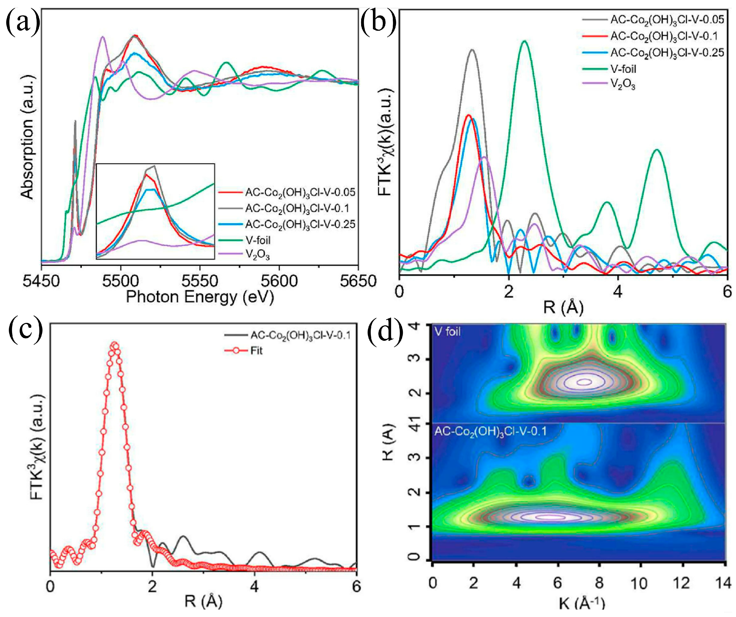
  79. Zhang, B.; Pan, C.; Liu, H.; Wu, X.; Jiang, H.; Yang, L.; Qi, Z.; Li, G.; Shan, L.; Lin, Y. Achieving High-Efficient Urea Oxidation via Regulating the Rate-Determining Step over a V Single Atom Incorporated Co Hydroxide Electrocatalyst. Chem. Eng. J. 2022, 439, 135768. [Google Scholar] [CrossRef]
  80. Behrens, M.; Studt, F.; Kasatkin, I.; Kühl, S.; Hävecker, M.; Abild-Pedersen, F.; Zander, S.; Girgsdies, F.; Kurr, P.; Kniep, B.-L. The Active Site of Methanol Synthesis over Cu/ZnO/Al2O3 Industrial Catalysts. Science 2012, 336, 893–897. [Google Scholar] [CrossRef]
  81. Liu, Y.; Hua, X.; Xiao, C.; Zhou, T.; Huang, P.; Guo, Z.; Pan, B.; Xie, Y. Heterogeneous Spin States in Ultrathin Nanosheets Induce Subtle Lattice Distortion to Trigger Efficient Hydrogen Evolution. J. Am. Chem. Soc. 2016, 138, 5087–5092. [Google Scholar] [CrossRef] [PubMed]
  82. Yan, D.; Li, Y.; Huo, J.; Chen, R.; Dai, L.; Wang, S. Defect Chemistry of Nonprecious-metal Electrocatalysts for Oxygen Reactions. Adv. Mater. 2017, 29, 1606459. [Google Scholar] [CrossRef]
  83. Lu, S.; Hummel, M.; Kang, S.; Pathak, R.; He, W.; Qi, X.; Gu, Z. Density Functional Theory Investigation of the NiO@ Graphene Composite as a Urea Oxidation Catalyst in the Alkaline Electrolyte. ACS Omega 2021, 6, 14648–14654. [Google Scholar] [CrossRef] [PubMed]
  84. Tu, Z.; Liu, X.; Xiong, D.; Wang, J.; Gong, S.; Xu, C.; Wu, D.; Chen, Z. Ultrafast Room-Temperature Activation of Nickel Foams as Highly Efficient Electrocatalysts. Chem. Eng. J. 2023, 475, 146253. [Google Scholar] [CrossRef]
  85. He, B.; Kuang, Y.; Hou, Z.; Zhou, M.; Chen, X. Enhanced Electrocatalytic Hydrogen Evolution Activity of Nickel Foam by Low-Temperature-Oxidation. J. Mater. Res. 2018, 33, 213–224. [Google Scholar] [CrossRef]
Figure 1. Schematic diagram of defect engineering of catalysts.
Energies 17 03801 g001
Figure 2. (a) EDX mapping of O, Ni and V in V-Ni(OH)2. (b) STEM image of V-Ni(OH)2. (c,d) Associated 3D pseudo-color surface plot of Ni(OH)2 and V-Ni(OH)2, Reprinted with permission from Ref. [58]. Copyright 2021, Wiley-VCH. (e) Illustration of the catalyst synthesis procedure, (f) HER activity of various catalysts, (g) UOR activity of various catalysts, (h) LSV comparing water and urea electrolysis on NF/P-NiMoO4−x, Reprinted with permission from Ref. [44]. Copyright 2023, Elsevier. (i) Scheme of the preparation process for ZnO-Ni2P/NF, (j) LSV curves of various electrodes for UOR, (k) LSV curves of ZnO-Ni2P/NF for UOR, (l) LSV curves: performance comparison of ZnO-Ni2P/NF for water and urea electrolysis, Reprinted with permission from Ref. [45]. Copyright 2024, Elsevier.
Energies 17 03801 g002
Figure 3. Fitting results for (a) Ni 2p3/2 and (b) O 1s of NiCo(OH)2; (c) Co 2p3/2 fitting result of NiCo(OH)2, Reprinted with permission from Ref. [76]. Copyright 2024, Wiley-VCH. (d) Scheme of the synthesis pathway for Mn-Ni(OH)2; (e) UOR activity of various catalysts. (f) Polarization curves of HER with various catalysts; (g) LSV curves obtained from the electrolytic cell during the processes of urea and water electrolysis, Reprinted with permission from Ref. [46]. Copyright 2022, American Chemical Society.
Energies 17 03801 g003
Figure 4. (a) Scheme of the synthesis procedure of S-Co2P@Ni2P. (b) HER polarization curves using various catalysts; (c) LSV curves comparing UOR and OER activity on various catalysts; (d) electrolysis performance of S-Co2P@Ni2P for both urea and water electrolysis. (e) Comparison of calculated adsorption free energies of various catalysts, Reprinted with permission from Ref. [47]. Copyright 2022, Elsevier. (f) Graphical depiction for Ru/P-NiMoO4@NF. (g) HER polarization curves with various catalysts. (h) LSV curves of the UOR of different catalysts. (i) LSV generated using Ru/P-NiMoO4@NF for overall seawater splitting and overall urea splitting in seawater. (j) XRD patterns of Ru/P-NiMoO4@NF, Reprinted with permission from Ref. [48]. Copyright 2023, Elsevier.
Energies 17 03801 g004
Figure 5. In situ Raman spectra of (a) NiO, (b) Ni/NiO and (c) Ni/NiO@CrOx. (d) In situ Raman spectra acquired at 1.334 V vs. RHE for Ni/NiO@CrOx across various time intervals, Reprinted with permission from Ref. [78]. Copyright 2012, Elsevier.
Energies 17 03801 g005
Figure 6. (a) Schematic diagram of the synthesis process for Ni-S-Se/NF. (b) LSV curves of various electrodes for HER. (c) Polarization curves of Ni-S-Se/NF in UOR and OER. (d) LSV curves of water electrolysis and urea electrolysis of Ni-S-Se/NF, Reprinted with permission from Ref. [49]. Copyright 2021, Elsevier. (e) Preparation diagram of c-CoNiPx/a-P-MnOy. (f) Electrochemical performance comparisons among electrodes for HER. (g) Polarization curves of Ni-S-Se/NF in UOR and OER. (h) LSV curves of water and urea electrolysis of c-CoNiPx/a-P-MnOy, Reprinted with permission from Ref. [50]. Copyright 2023, Elsevier.
Energies 17 03801 g006
Figure 7. (a) XANES spectra of V K-edge were recorded for the AC-Co2(OH)3Cl-V-n samples, with comparisons made to the V foil and V2O3 standard spectra. (b) The k3-weighted FT-EXAFS spectra in R space were generated for the AC-Co2(OH)3Cl-V-n samples and contrast samples. (c) The FT-EXAFS spectrum for AC-Co2(OH)3Cl-V-0.1, along with its corresponding fitting curve. (d) WT-EXAFS curves of the V K-edge for AC-Co2(OH)3Cl-V-0.1 and V foil, Reprinted with permission from Ref. [79]. Copyright 2022, Elsevier.
Energies 17 03801 g007
Figure 8. (a) Schematic depicting the synthesis of Pt/D-NiCo LDH nanostructures. (b) Aberration-corrected AC-HRTEM images showing uniformly distributed bright dots marked by dotted red and blue circles, indicating atomically dispersed Pt atoms. (c) LSV curves of different catalysts for UOR. (d) LSV curves of various electrodes for HER. (e) LSV curves for water and urea electrolysis of Pt1/D-NiCo LDH-24, Reprinted with permission from Ref. [51]. Copyright 2023, Elsevier. (f) Scheme of the preparation strategy to achieve high-loading RhSA sites stabilized on S-Co3O4/NF. (RhSA-S-Co3O4/NF). (g) LSV curves of RhSA-S-Co3O4/NF for UOR and OER. (h) LSV curves for water and urea electrolysis using bifunctional RhSA-S-Co3O4/NF in alkaline media. (i) Reaction free energy profiles on S-Co3O4 and RhSA-S-Co3O4 surfaces for UOR, Reprinted with permission from Ref. [52]. Copyright 2021, The Royal Society of Chemistry.
Energies 17 03801 g008
Figure 9. (a) Diagram depicting the synthesis of M-FeNi LDH. (b,c) HRTEM image of FeNi LDH and Mo-FeNi LDH. (d) LSV curves for UOR on various electrodes. (e) Polarization curves for water and urea electrolysis using Pt/C||Mo-FeNi LDH, Reprinted with permission from Ref. [53]. Copyright 2024, Wiley-VCH. (f) Synthesis schematic of Ru-NiO/p-Ni. (g) XRD spectra of different materials. (h) LSV curves for OER and UOR using Ru-NiO/p-Ni. (i) Polarization curves for water and urea electrolysis using Ru-NiO/p-Ni as both electrodes, Reprinted with permission from Ref. [54]. Copyright 2024, Elsevier.
Energies 17 03801 g009
Figure 10. (a) Diagram of the core/branch structure of TiO2@Ni3S2 arrays. (b,c) HRTEM image of TiO2@Ni3S2. (d) OER’s LSV curves on various electrodes. (e) HER’s LSV curves on various electrodes. (f) Polarization curves of TiO2@Ni3S2||TiO2@Ni3S2 for water and urea electrolysis, Reprinted with permission from Ref. [55]. Copyright 2019, Springer. (g) Scheme of the synthetic procedure for TiO2 NWAs and NPAs. (h) HRTEM images of TiO2 NPAs. (i) SAED pattern of TiO2 NPAs. (j) SEM images of TiO2 NPAs, with cross-sectional (top-right) and side-view (bottom-left) insets. (k) Polarization curves of different electrodes, Reprinted with permission from Ref. [56]. Copyright 2021, Elsevier.
Energies 17 03801 g010
Table 1. Comparison of properties of different materials.
CatalystsHER ActivityUOR ActivityWater ElectrolysisUrea ElectrolysisRefs.
NF/P-NiMoO4 x 116 mV
(vs. RHE)
10 mA cm−2
1.59 V
(vs. RHE)
100 mA cm−2
1.66 V 10 mA cm−21.48 V 10 mA cm−2[44]
ZnO-Ni2P/NF (a)-1.347 V
(vs. RHE)
50 mA cm−2
1.667 V 50 mA cm−21.529 V 50 mA cm−2[45]
Mn-Ni(OH)2/CP −76 mV
(vs. RHE)
10 mA cm−2
1.347 V
(vs. RHE)
10 mA cm−2
1.61 V 10 mA cm−21.407 V 10 mA cm−2[46]
S-Co2P@Ni2P 103 mV
(vs. RHE)
100 mA cm−2
1.36 V
(vs. RHE)
100 mA cm−2
1.52 V 10 mA cm−21.43 V 10 mA cm−2[47]
Ru/P-NiMoO4@NF 0.23 mV
(vs. RHE)
3000 mA cm−2
1.46 V
(vs. RHE)
1000 mA cm−2
-1.73 V 500 mA cm−2[48]
Ni-S-Se/NF 98 mV
(vs. RHE)
10 mA cm−2
1.38 V
(vs. RHE)
10 mA cm−2
1.57 V 10 mA cm−21.47 V 10 mA cm−2[49]
c-CoNiPx/a-P-MnOy100 mV
(vs. RHE)
10 mA cm−2
1.35 V
(vs. RHE)
100 mA cm−2
2.0 V 100 mA cm−21.67 V 100 mA cm−2[50]
Pt1/D-NiCo LDH (b)-24 37 mV
(vs. RHE)
10 mA cm−2
1.25 V
(vs. RHE)
10 mA cm−2
1.52 V 10 mA cm−21.32 V 10 mA cm−2[51]
RhSA(c)-S-Co3O4/NF45 mV
(vs. RHE)
10 mA cm−2
1.28 V
(vs. RHE)
10 mA cm−2
-1.33 V 10 mA cm−2[52]
Mo-FeNi-LDH (b)-1.32 V
(vs. RHE)
10 mA cm−2
1.49 V 10 mA cm−21.38 V 10 mA cm−2[53]
Ru-NiO/p-Ni 127 mV
(vs. RHE)
10 mA cm−2
1.39 V
(vs. RHE)
100 mA cm−2
1.75 V 100 mA cm−21.58 V 100 mA cm−2[54]
TiO2@Ni3S2112 mV
(vs. RHE)
10 mA cm−2
-1.58 V 10 mA cm−2-[55]
Ni/TiO2 NPAs (d)88 mV
(vs. RHE)
10 mA cm−2
---[56]
(a) nickel foam (NF); (b) layered double hydroxide (LDH); (c) Rh single atom (RhSA); (d) TiO2 nanopyramid arrays (NPAs).
Table 2. Comparison of preparation methods and defect types.
CatalystsPreparation MethodType of DefectsRefs.
a-Ni(OH)2Template MethodVacancy defects[57]
V-Ni(OH)2One-step hydrothermal methodVacancy defects[58]
Mo-NiS/Ni3S2Hydrothermal sulfurization–acid-assisted etchingVacancy defects[59]
(a) VNi-α-Ni(OH)2Alkaline precipitation methodVacancy defects[60]
NiFe LDH (b)@Ni(OH)2Electrodeposition and in situ etchingVacancy defects[61]
Co-NiMoO4/NFHydrothermal and impregnationHeteroatom doping[62]
P-NiMoO4Acid etching and oxidative synthesisHeteroatom doping[44]
Ru/P-NiMoO4@NFHydrothermal synthesis and thermal treatmentHeteroatom doping[48]
S-Co2P@Ni2P Chemical deposition and low-temperature phosphidationHeteroatom doping[47]
Ni/Ni3S2@NClectrodeposition and thermal treatmentHeteroatom doping[63]
Ni/r-Ni(OH)2@CPlasma-enhanced chemical vapor depositionHeteroatom doping[64]
Mn-Ni(OH)2ElectrodepositionHeteroatom doping[65]
Ni-TPA (c)@NiSe Hydrothermal synthesisAmorphization[66]
Ni(OH)2–NiMoOx/NF Template method and electrodepositionAmorphization[67]
Ni(OH)S/NF Solvothermal synthesis and annealingAmorphization[68]
NiFe hydroxide Chemical corrosion Amorphization[69]
Nickel carbonate Chemical precipitationAmorphization[70]
Fe-O-PAtomic layer deposition–phosphorizationAmorphization[71]
NiOx/N-doped Chemical reductionAmorphization[72]
RhSA-S-Co3O4Hydrothermal synthesis and rapid quenchingSingle-atom design[52]
Pt/D-NiCo LDH SACs (d)Electrodeposition and etching treatmentSingle-atom design[51]
Ir-NiFe-OH Hydrothermal synthesisSingle-atom design[73]
TiO2@Ni2(OH)2CO3Atomic layer depositionHigh-index facets[55]
Ni3S2 Nanosheet Hydrothermal synthesisHigh-index facets[74]
(a) nickel vacancy (VNi); (b) layered double hydroxide (LDH); (c) nickel–terephthalic acid (Ni-TPA); (d) single-atom electrocatalysts.
Disclaimer/Publisher’s Note: The statements, opinions and data contained in all publications are solely those of the individual author(s) and contributor(s) and not of MDPI and/or the editor(s). MDPI and/or the editor(s) disclaim responsibility for any injury to people or property resulting from any ideas, methods, instructions or products referred to in the content.

