Abstract
With the increasing demand for renewable energy worldwide, lithium-ion batteries are a major candidate for the energy shift due to their superior capabilities. However, the heat generated by these batteries during their operation can lead to serious safety issues and even fires and explosions if not managed effectively. Lithium-ion batteries also suffer from significant performance degradation at low temperatures, including reduced power output, a shorter cycle life, and reduced usable capacity. Deploying an effective battery thermal management system (BTMS) is crucial to address these obstacles and maintain stable battery operation within a safe temperature range. In this study, we review recent developments in the thermal management and heat transfer of Li-ion batteries to offer more effective, secure, and cost-effective solutions. We evaluate different technologies in BTMSs, such as air cooling, liquid cooling, phase change materials, heat pipes, external preheating, and internal preheating, discussing their advantages and disadvantages. Through comparative analyses of high-temperature cooling and low-temperature preheating, we highlight the research trends to inspire future researchers. According to the review of the literature, submerged liquid BTMS configurations show the greatest potential as a research focus to enhance thermal regulation in Li-ion batteries. In addition, there is considerable research potential in the innovation of air-based BTMSs, the optimization of liquid-based BTMSs, the coupling of heat pipes with PCMs, the integration of PCMs and liquid-cooled hybrid BTMSs, and the application of machine learning and topology optimization in BTMS design. The application of 3D printing in lithium-ion battery thermal management promises to enhance heat transfer efficiency and system adaptability through the design of innovative materials and structures, thereby improving the battery’s performance and safety.
1. Introduction
In light of the worldwide scarcity of fossil fuels and rising levels of environmental contamination, there is a strong desire for safer, more environmentally friendly, and more effective energy alternatives. Lithium-ion batteries are essential in the emerging energy sector due to their minimal self-discharge, superior energy density, extended cycle life, and efficient operation [1].
However, while there are many factors that affect lithium-ion batteries, the most important factor is their sensitivity to thermal effects. Lithium-ion batteries perform best when operating between 15 °C and 35 °C, with a maximum temperature difference of 5 °C within the battery module [2]. Deviations from this temperature range can impact the battery’s performance and safety [3]. The accelerated decomposition of solid electrolyte phase interface (SEI) membranes at high ambient temperatures increases the risk of thermal runaway [4]. In addition, lithium-ion batteries are susceptible to fire and explosions due to elevated temperatures if they do not dissipate heat effectively [5]. In a low-temperature environment, lithium batteries exhibit a low capacity, serious attenuation, and poor cycle rate performance; moreover, the lithium precipitation phenomenon is obvious, de-embedded lithium imbalance can occur, and so on [6,7]. This not only affects the charging and discharging efficiency but also generates lithium dendrites due to lithium precipitation at low temperatures, which affects the cycle life of the battery and may even lead to the early retirement of the battery in severe cases. As a result, the safety standards for the thermal control of lithium batteries have become more demanding, necessitating ongoing enhancements.
A large number of studies and reviews exist on the current thermal management methods for lithium batteries. Khan et al. [8] addressed a hybrid BTMS coupled with PCMs and investigated the effect of the PCM chamber layout and fin surface on the system’s performance. Exploring the impact of vibration on phase change materials (PCMs) in lithium-ion battery thermal management systems, a PCM is suggested as a possible remedy for the vibration issue. Pu et al. [9] have improved the performance of nickel-rich cathode materials through antimony doping. Similarly, Liu et al. [10] have successfully regenerated severely degraded nickel-rich cathodes using an organic lithium salt-assisted eutectic salt direct regeneration method. Garud et al. [11] focused on phase change material cooling and direct liquid cooling, providing a comprehensive review of a variety of recent experimental and numerical studies based on these two strategies. The current research prioritizes direct liquid cooling as an emerging technology due to the practicality and constraints of phase change material cooling. The recent advancements in the adsorption characteristics of phase change materials (PCMs) in porous materials and their combination with polymers through melt blending or copolymerization have been examined by Zhao et al. [12]. These methods not only enhance the shape stability of the materials but also improve their mechanical properties. In addition, composite phase change materials (CPCMs), prepared by combining flame retardants and inorganic phase change materials, are expected to solve the flammability problem of these materials. Research indicates that upcoming studies should prioritize improving the assembly methods to decrease the interfacial thermal resistance in CPCMs, strengthen their mechanical characteristics, and improve the feasibility of manufacturing CPCM-based BTMSs. Hwang et al. [13] explored four common battery thermal management methods, namely air cooling, liquid cooling, phase change materials, and thermoelectric systems, and evaluated the advantages and disadvantages of each. It was found that air cooling is suitable for short-distance EVs, liquid cooling is suitable for long-distance EVs with large batteries and high thermal loads, phase change materials are suitable for stable temperature loads and ambient temperatures, and thermoelectric systems are better suited to being used in combination with other thermal management technologies to achieve better thermal control. A thorough examination, comparison, and discussion of low-temperature preheating methods for lithium-ion batteries were given by Wang et al. [14]. They discussed the fundamental operational principles of each preheating method, examining and contrasting the different technologies extensively to evaluate their advantages and disadvantages across five crucial aspects: the speed of the temperature increase, temperature variations, expenses, compatibility with batteries, and safety and dependability.
Nevertheless, these studies are not without constraints, and they present possibilities for additional exploration. As it can be seen from the above reviews, they either focus on cooling strategies at high temperatures, the review of technologies for low-temperature preheating, or recent advances in a specific method. This study fills this void by conducting a thorough examination of the progress of air cooling, liquid cooling, phase change materials, heat pipes, and different preheating technologies. It includes detailed comparative analyses, as well as a synthesis of the advantages and disadvantages of each cooling method, and suggests practical integration solutions. Section 2 of this review considers the mechanistic analysis of heat generation in lithium-ion batteries. Section 3 focuses on the technological development of low-temperature preheating. The focus of Section 4, Section 5, Section 6 and Section 7 is on the most recent developments in cooling using air-cooled or liquid-cooled heat pipes and phase change materials. Section 8 focuses on future challenges and trends. The structure of this review is depicted in Figure 1.
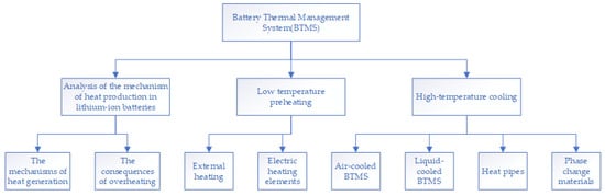
Figure 1.
Review analysis framework diagram.
2. Analysis of the Mechanism of Heat Production in Lithium-Ion Batteries
The optimal performance of lithium-ion batteries occurs at temperatures between 15 and 35 °C. Extreme temperatures can hinder the functionality of lithium-ion batteries. Elevated temperatures initiate the growth of the SEI (solid electrolyte interface) and decomposition of the SEI, the binder, and the electrolyte. Conversely, localized hot spots and low temperatures initiate the formation of lithium plating/dendrites, resulting in degradation of the capacity and power [15,16]. Below, the mechanisms of heat generation in lithium-ion batteries and the consequences of overheating are discussed separately.
2.1. The Mechanisms of Heat Generation
Lithium-ion batteries generate heat during charging and discharging. The internal operating principles of the lithium-ion battery charging and discharging processes are illustrated in Figure 2. This heat production encompasses reversible heat from electrochemical reactions, heat generated by ohmic resistance, heat due to polarization resistance, heat from electrolyte decomposition, and heat from the decomposition of the solid electrolyte interphase (SEI) film [17,18]. Heat is generated in the battery through the movement of lithium ions from the cathode to the anode, resulting in a sequence of chemical reactions within the battery that produce heat. The internal resistance of a battery generates heat as the current passes through it, a phenomenon determined by Ohm’s Law, where the heat produced is directly proportional to the square of the current, the resistance, and the time the current flows. During battery operation, polarization occurs, leading to the creation of polarization resistance, which also generates heat when the current passes through it, primarily due to the irreversibility of the internal electrochemical reactions within the battery.
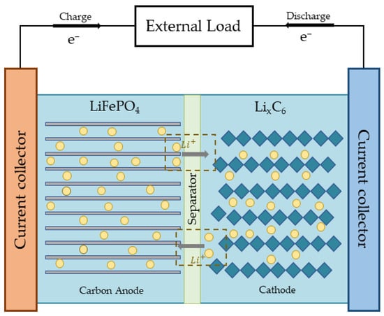
Figure 2.
Internal working principle of LIBs.
During the charge and discharge processes of a battery, the electrochemical reactions at the anodes and cathodes are reversible, but these processes are accompanied by heat generation. The electrolyte may decompose during battery operation, especially under high temperatures or overcharging conditions, releasing heat in the process. When temperatures exceed 90 °C, the solid electrolyte interphase (SEI) film begins to decompose, causing the anode material to react with the solvent and release heat. As temperatures continue to rise, a series of thermal events can occur, including separator melting, anode–cathode short-circuiting, binder decomposition, cathode material breakdown, and melting of aluminum current collectors, leading to a rapid aggregation of heat, potentially resulting in fire and explosion. Currently, it is challenging to accurately measure the polarization internal resistance of lithium-ion batteries during operation through experimental means [19]. Consequently, Bernardi’s empirical correlation from 1980 is the most commonly utilized formula for determining a battery’s heat rate.
Q represents the heat produced by the cell, I stands for the nominal current, OCV is the open circuit voltage, V represents the nominal voltage, and is the temperature of the cell. The initial component of Equation (1) represents the heat generated through the Joule heating effect, which is mainly due to electrical energy losses. The second term usually denotes the heat generated due to entropy generation during electrochemical reactions. It should be mentioned that the heat produced from entropy alteration is relatively minimal at lower discharge rates in contrast to higher discharge rates, not higher.
This occurs when the battery is discharged at high rates, causing an increase in the reaction rate and potentially resulting in greater heat production, including heat from irreversible entropy generation [20]. The rate of cell heat generation is related to various factors, such as the SOC, temperature, and C-rate [21].
Nevertheless, practical engineering applications still face numerous obstacles, and several researchers have explored Bernardi’s empirical equations with additional modifications. In their study, a new method for predicting the heat generation rate (HGR) of lithium-ion batteries was suggested by Wu et al. [21], utilizing experimental data and a back-propagation neural network (BPNN) to enhance prediction accuracy. It was discovered that the classic Bernardi empirical formula shows notable discrepancies when predicting the heat characteristics of batteries, particularly during intense discharge and in hot environmental settings. To solve this problem, Wu et al. proposed an updated HGR prediction model that corrects the prediction error of Bernardi’s equation using the BPNN method and successfully controls the prediction error within 5%. Their work provides a more reliable HGR prediction tool for battery thermal management and helps to improve the thermal control strategy of batteries.
2.2. The Consequences of Overheating
The heat produced by a lithium-ion battery originates in its center and then radiates outward. Unequal heat-dissipation areas and varying thermal conductivity can lead to inconsistent temperature distribution within and among cell layers. To ensure optimal performance and safety of the system, it is crucial to keep the battery surface temperature fluctuation range and temperature variance between batteries and modules under 5 °C. This is essential for the efficient and stable operation of the system [22]. Two common consequences of lithium-ion battery operation at high temperatures are thermal aging and runaway.
When the operating temperature of lithium-ion batteries exceeds the upper limit of their optimal working range, it significantly accelerates the aging rate of the batteries, thereby leading to a decline in battery performance. This performance degradation is primarily reflected in the reduction of the battery’s available energy and power output capability. In the context of high-temperature aging, the capacity fade rate of the batteries exhibits an accelerated trend, the internal resistance increases accordingly, and the thermal safety also decreases. These combined changes have a negative impact on the overall performance metrics and the safety attributes of lithium-ion batteries [23].
As temperatures continue to rise, this can lead to a reduction in the battery’s power and capacity and may potentially trigger the occurrence of thermal runaway phenomena. These conditions could all initiate fire, smoke generation, and the emission of harmful gases and induce decomposition reactions of the electrolyte with electrode materials [24]. These changes in the thermophysical direction will trigger thermal gradients within the Li-ion battery, which will result in the loss of capacity and rapid aging of the battery. Therefore, for lithium-ion batteries, the selection of thermal management strategies and cooling technologies is of great significance in ensuring the overall performance and extending the service life of the batteries.
3. Low-Temperature Preheating
Lithium batteries experience a notable decrease in performance in cold temperatures, affecting various indicators and posing safety risks. The charge acceptance [25], output power and energy density, and battery life [26] of Li-ion batteries at low temperatures are negatively affected to varying degrees. In addition, the low-temperature environment increases the safety risk of the battery [27]. A study by Nagasubramanian et al. [28] demonstrated the particular impact of decreased temperature on the functionality of lithium-ion batteries. When the temperature drops to −40 °C, the Li-ion battery’s power output decreases to just 1.25% of what it is at 25 °C, while the energy density also drops significantly to 5%, indicating a severe decline in performance at low temperatures. The study by Ouyang et al. [29] specifically examined how low temperatures impact the performance of Li-ion batteries. Following 40 cycles of charging and discharging 11.5 Ah lithium-ion batteries at a 0.5C rate in −10 °C conditions, the batteries experienced a 25% decrease in capacity, highlighting the substantial impact of low temperatures on lithium-ion battery performance. In addition, Piao et al. [30] pointed out the safety hazards of lithium batteries in low-temperature environments. At low temperatures, graphite-negative electrodes are easily coated with lithium metal, forming lithium dendrites. This lithium dendrite may penetrate the diaphragm, leading to an internal short circuit of the battery, which may lead to serious consequences, such as thermal runaway. Hence, it is important to be cautious of the decline in performance and potential safety hazards when utilizing lithium batteries in cold temperatures.
Battery preheating technology is an important countermeasure to effectively mitigate the performance degradation of lithium batteries in cold environments and reduce safety risks. Preheating methods can be categorized into external heating and internal heating based on various energy supply methods. The external heating method can be specifically subdivided into two kinds: one is the heating method based on the BTMS system, and the other is the preheating mode realized by using thermoelectric elements. Internal heating methods can also be further differentiated into two categories: one is the self-heating mode, and the other is the preheating method achieved through current excitation.
3.1. External Heating
External heating methods to heat the battery from the outside are easy to implement, usually in combination with cooling in the BTMS or using electric heating elements. In external heating, the battery pack heats the working fluid by driving electrical heating elements, such as resistance wires.
3.1.1. BTMS-Based Technology
In this section, the BTMS-technology-based heating approach will be discussed in four segments: air-cooled, liquid-cooled, phase change material, and heat pipe. Air-cooled BTMS technology utilizes an external heat source to warm the air, which is then circulated through a fan to preheat the battery pack [31]. This method efficiently applies airflow and heat transfer principles for consistent battery preheating. Typically, the rate at which the temperature of the air increases during preheating is quite slow, approximately 0.5 °C/min, because of its low thermal conductivity, limited heat capacity, and uneven temperature distribution [14]. The form of the air cooling arrangement is shown in Figure 3.
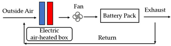
Figure 3.
Schematic of air-based preheating.
Liquid preheating technology is more efficient than air preheating technology because of its higher thermal conductivity and heat capacity, allowing for a quicker temperature increase [32]. Fan et al. [33] constructed a three-dimensional model containing six batteries and hot/cold plates to study the effects of the battery discharge rate, the heating medium mass flow rate, and the inlet temperature at a low temperature of −20 °C. The findings indicate that the rate of discharge has a minor impact. When using an external heat source, increasing the mass flow rate improves the heating performance, but the effect is limited beyond 0.065 kg. Increasing the inlet temperature accelerates heating, but it may lead to overheating of the cell. The impact of the heat transfer fluid (HTF) inlet flow and temperature, battery gap, number of batteries, and HTF inlet and outlet positions on the preheating efficiency of immersion preheating systems was examined by Wang et al. [34]. Simulation results show that the IPS is capable of reaching temperature increases of up to 4.18 °C per minute, with a battery pack temperature variation of under 4 °C.
A PCM requires less energy than air-cooled and liquid-cooled systems, which need additional accessories for installation. J et al. [35] designed a preheating management system for high-capacity Li-ion ternary batteries using a novel coupled preheating method using a heated film and a PCM. A numerical analysis was conducted to examine the impact of four key factors (the power of the heating film, variations in the heating film power, the distance between cells, and the thickness of the PCM) on the preheating of battery packs in order to identify the most effective parameters for the integrated preheating control system. At temperatures of 253.15 K, 263.15 K, and 273.15 K, the fast preheating method significantly decreases the preheating time compared to traditional preheating, with a temperature difference of approximately 1.48 K and temperature rise rates of 1.29 °C/min, 1.26 °C/min, and 1.18 °C/min, respectively.
In recent years, heat pipes, as a superior heat transfer method, have gradually attracted much attention for their application in the field of battery preheating. Chen et al. [36] proposed a pulsed heat pipe based on TiO2 nanofluid as a heating module for power batteries of pure electric vehicles. Experimental data indicate that TiO2-CLPHP exhibits optimal heat transfer efficiency at a working medium concentration of 2% and a heat pipe filling ratio of 50%. Furthermore, at temperatures of −10 °C, −20 °C, and −30 °C, the battery surface experienced average warming rates of 1.43 °C/min, 1.62 °C/min, and 2.23 °C/min, respectively. Liang et al. [37] developed a BTMS utilizing an FMHPA to achieve module-level preheating and cooling integration. Experimental findings indicate that the rate of temperature increase can reach approximately 1 °C per minute when the ambient temperatures are −20 °C, −10 °C, and 0 °C while maintaining a temperature gap of no more than 5 °C between the cell and the module levels.
3.1.2. Electric Heating Elements
The electric heating element is precision-fitted to the surface of the battery and designed to realize the direct conversion of electrical energy to thermal energy. This process is carried out efficiently through a heat transfer mechanism for preheating purposes. With regard to the preheating methods of electric heating elements, three main methods can be summarized: Peltier effect preheating, resistance heating preheating, and electric heating film preheating.
Peltier effect preheating, a technique based on the thermocouple effect, achieves localized heating of the battery surface through the difference in heat generated by an electric current at the interface of two different metals. The battery’s heat dissipation can be achieved by simply changing the current direction in the Peltier element. This method is uniquely suited to precisely controlling the temperature distribution and heating rate, with the flexibility to adjust the current to control preheating and cooling intensity [38]. Resistance heating preheating, on the other hand, utilizes the resistance properties of the electric heating element itself to generate heat when energized. The principle of this method is simple, direct, and easy to realize. As shown in Figure 4, common resistance preheating structures include electric hot plate preheating and electric hot box preheating. The temperature and speed of heating can be flexibly controlled by adjusting the current and voltage. Common materials are positive temperature coefficient resistors and metal resistors. Zhang et al. [39] studied a PTC preheating device powered by the battery pack itself. Approximately 13% of the total energy of the battery pack was used during the self-heating test, resulting in an average RTR of 4.09–4.60 °C/h for the outer cell and 2.10–3.44 °C/h for the inner cell.
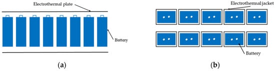
Figure 4.
Common structure of resistance heating preheating: (a) preheating of electric heating plates; (b) preheating of electric heating jacket.
The electric heating film is usually made of insulated metal foil. When energized, the electric heating film rapidly generates a uniform heat field, realizing a comprehensive preheating of the battery surface. A broadband metal film heating method was proposed by Lei et al. [40]. Experimental results show that a battery pack heated by a broadband metal film is capable of charging and discharging at high currents and delivering close to 80% power at −40 °C ambient temperature. After 15 min of 90 W power heating, the pack was able to achieve discharge currents of up to 6C to 8C at −40 °C, with a discharge capacity of 80% of the capacity discharged at room temperature. The study by Yang et al. [41] examined how batteries’ temperatures change when discharged at low temperatures and when preheated using a polyimide (PI) flexible heating film. They developed and confirmed the accuracy of a battery electrical heating model and a preheating model based on a second-order equivalent circuit model (ECM). Results from the experiments indicated that the rates of temperature increase when preheating the cell from −10 °C to 25 °C were 5.32 °C/min, 11.05 °C/min, and 16.67 °C/min at heating film powers of 1 W, 3 W, and 5 W, respectively.
3.2. Internal Heating
Internal heating is mainly divided into self-heating and current excitation. Internal heating, unlike external heating, allows for quicker temperature response and is not constrained by the battery’s shape. The control system for the preheating process is complex and could potentially lead to safety issues with the battery pack.
3.2.1. Self-Heating Technology
SHLB preheating technology has obvious advantages in preheating large and thick cells, with very high heating efficiency and speeds about 40 times faster than existing methods. A self-heating lithium-ion battery (SHLB) was created by Wang et al. [42] that can warm itself in below-freezing conditions without requiring external heating devices or electrolyte enhancements. The concept involves a lithium-ion battery containing a dual-tabbed nickel foil that is heated through ohmic heating. The negative terminal is connected to one tab, while the other tab serves as the activation terminal that can be controlled by a switch. When the temperature is low, the switch is turned on, allowing the current to pass through the nickel foil in order to produce heat that warms the battery cell; once the desired temperature is reached, the switch is turned off to cease the heating process and revert back to a standard lithium-ion battery. Research indicates that battery usage decreases to 3.8% and 5.5% of its full capacity after 20 s and 30 s at internal temperatures of 0 °C, −20 °C, and −30 °C, respectively. In addition, the battery discharges/regenerates 6.4 to 12.3 times the power of existing lithium-ion batteries at −30 °C. A new heating approach with an adjustable duty cycle was suggested by Lin C et al. [43], utilizing a real-time, two-dimensional model to enhance the evenness of temperature distribution in SHLB while heating. A combined thermal–electrical model provides real-time 2D battery temperature mapping, achieving a maximum 1.2 °C temperature difference. It reduces the computation time by 90% compared to FEM models. The strategy auto-adjusts the heating current duty cycle to enhance uniformity, cutting temperature differences by 35% and maintaining it within a set range, improving battery management.
3.2.2. Current Excitation Methods
There are three primary modes of the current stimulation method, which are DC preheating, AC preheating, and pulse preheating, based on the current type. Various methods for applying the current fall under the umbrella of the current excitation technique.
In DC preheating, because charging at low temperatures may create the risk of precipitating lithium, the discharge self-heating method is more mainstream and is divided into two modes: the constant-voltage discharge method and the constant-current discharge method. In the preheating process, the battery is heated by internal ohmic and polarization resistors. An electrochemical–thermal model was utilized to replicate the heating of lithium-ion batteries from temperatures below freezing by Ji et al. [44]. Constant-current discharge briefly lowered performance, while constant-voltage discharge offered higher heating efficiency. Ruan H et al. [45] predicted a temperature rise and capacity loss at low temperatures using a battery heat model. An optimized heating strategy raised the temperature from −30 °C to 2.1 °C in 103 s, with a 1.4% capacity loss. This boosted discharge/charging in the cold, enhancing energy output 62.46-fold.
AC power heats batteries through cyclic charging and discharging to achieve rapid heating while maintaining a stable battery SOC. The amplitude, frequency, and voltage of the AC current will have an effect on the preheating effect. The amplitude of the current is large, resulting in a fast ramp and a high initial SOC [46]. At low-frequency currents, the cell impedance is high, and heating is effective [47]. Continuous adjustment of the current amplitude accelerates warming [48]. The battery heating time decreases when the AC voltage frequency increases. Zhang L et al. [49] studied AC heating of batteries, finding optimal current amplitude via EIS tests. An equivalent circuit model predicted battery heat. Their multi-stage AC heating strategy heated batteries from −20 °C to 0 °C in 5 min safely. Shorter current durations speed up heating.
Pulse preheat technology involves indirect heating of the battery with an intermittent current signal, which utilizes the battery’s internal impedance to generate heat. Compared to constant DC or AC preheating methods, pulse preheating significantly reduces the loss of battery capacity while minimizing potential damage to the battery. Li et al. [50] used a motor to transfer the current between two battery modules, speeding up heating. Their DMSI mode achieved a higher heating current at a lower frequency, outperforming pulse current heating. At −7 °C, the battery pack heated at 8.6 °C/min, with 4.9% capacity loss. Pulse preheating, though uniform, requires complex, costly circuitry.
4. Air-Cooled BTMS
An air-cooled BTMS can be categorized into natural convection air cooling and forced convection air cooling according to the specific layout of the battery enclosure. In real-world scenarios, lithium-ion batteries are arranged in parallel or series within the battery enclosure, making it challenging for heat to be dissipated efficiently through natural convection. The battery’s heat dissipation requirements cannot be met by natural convection, but forced-air cooling can effectively regulate the battery temperature to the desired level. As battery systems evolve towards higher energy densities and more compact designs, natural convection may fail to meet cooling demands, whereas forced convection can more effectively manage heat flow and accommodate compact designs.
In certain applications, such as electric vehicles, forced convection can rapidly respond to instantaneous thermal loads, ensuring battery performance. An actively controlled and monitored forced convection system can enhance the reliability and lifespan of the battery system, mitigating performance degradation and safety risks associated with overheating. Therefore, while natural convection may be feasible in certain scenarios, forced convection offers more efficient cooling, superior temperature control, and adaptability, which are crucial for ensuring the performance and safety of lithium-ion batteries under various operating conditions. At present, a large number of studies have been put into the study of factors affecting the effect of air cooling, including the battery array layout, the airflow direction, the cooling channel structure, etc.
4.1. Battery Array Arrangement
The positioning of the batteries in the array impacts the airflow, subsequently influencing the cooling efficiency of the system. Maximizing the thermal efficiency, minimizing cost, reducing size, and increasing energy density are all key considerations when optimizing the battery pack structure through careful arrangement of battery cells [51]. It is worth emphasizing that the ideal battery array layout is tailored based on the specific application and design specifications of the battery pack [52]. Fan et al. [53] assessed and contrasted the cooling efficiency of battery packs arranged in aligned, staggered, and crossover configurations while examining how the thermal management system is impacted by the discharge rate and the inlet temperature. Aligned battery packs cool best, maintaining uniform temperatures. Parasitic power consumption rises with air intake velocity, but aligned packs consume up to 23% less than cross-aligned ones. Du et al. [54] studied four cell layouts, square, staggered, and trapezoidal, using 2D-cell and 3D-CFD models. The square layout performed best for air cooling. Tao Hai et al. [55] analyzed the co-cooling of plate and cylindrical batteries, revealing that the battery temperature decreases along with the airflow direction and that plate batteries are warmer. The study also showed an increase in the heat transfer coefficient with increased battery spacing. Kirad et al. [56] studied the forced-air cooling of 30 Li-ion batteries, focusing on spacing effects. Transverse spacing significantly impacts cooling, while longitudinal spacing mainly affects temperature uniformity. Liao et al. [57] proposed a four-step optimization method to design more efficient, cooler, and uniformly heated battery packs. This reduced the maximum temperature by 2.7 K and the temperature’s standard deviation by 0.3 K. Peng et al. [58] studied a realistic thermal model that accounts for the inconsistent thermal performance among battery cells. The study recommends strategic cell placement by positioning high-calorific cells near air inlets and exhausts for optimal placement and situating low-calorific cells in cooler-deficient regions to promote uniform temperature distribution.
4.2. Airflow Direction Influence
Convection heat transfer between the air entering the system and the battery cells is the primary method of heat transfer in the active air-cooled battery thermal management system. Cold air is introduced at the beginning of the airflow, where it absorbs and removes the heat produced by the battery by exchanging heat with the battery cells. It is then transformed into hot air with a higher temperature and exits at the end of the airflow. The change in temperature causes a notable temperature difference in the airflow’s direction, potentially resulting in unequal temperature distribution across the battery cells. To address temperature inconsistencies in battery packs, certain design solutions enhance the layout of heat dissipation channels by focusing on one-way flow to enhance heat transfer and distribution. Different battery packs utilize a reciprocating airflow system that alters the airflow direction to facilitate heat redistribution, aiding in the movement of heat from areas of high temperature to those of low temperature, ultimately minimizing temperature discrepancies among battery cells. In addition to this, the airflow reversal also creates boundary layer disturbances that help to disrupt the temperature boundary layer that has been formed, further improving the heat exchange efficiency of the system.
The cooling efficiency of an air-cooled BTMS can be influenced by the positioning and quantity of inlets and outlets, as well as the design of the heat dissipation pathways, in a unidirectional-flow battery thermal management setup. Varied positions of air intakes and exhausts may alter the airflow direction and distribution within the battery module, consequently impacting cooling efficiency and temperature consistency.
As shown in Figure 5, an investigation was conducted on a compulsory air-cooling mechanism designed for extensive lithium-ion battery modules by Wang et al. [59]. Case 1’s design achieved a more uniform temperature and efficient cooling (73%), improving battery safety. This highlights the importance of cooling channel design for battery thermal management. Du et al. [54] examined a cooling system utilizing forced air for extensive lithium-ion battery modules. Pan et al. [60] studied outlet positions and found optimal cooling on the upper right side of the battery module. Optimizing inlet/outlet locations improves cooling efficiency and temperature uniformity by changing airflow paths.
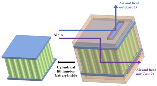
Figure 5.
Schematic diagram of air-cooling system.
As shown in Figure 6, the reciprocating cooling system is an ingeniously designed method that periodically changes the direction of the airflow by operating a flap door [61]. Yu et al. [62] designed a bi-directional airflow system with dual ducts and fans for battery packs. It lowered the maximum temperature from 42.3 °C to 33.1 °C, enhancing temperature uniformity. The jet cooling and the separate fans minimized hot spots, improving heat transfer and overall cooling. Wang et al. [63] experimentally optimized a reciprocating air-cooling strategy for a Z-type BTMS, reducing the maximum temperature difference by 65.5%. The study investigated how to regulate the temperature of extensive lithium-ion battery packs using alternating flow and active monitoring by Wang et al. [64]. An experimental platform was developed in the study to show how reciprocating cooling flow combined with active control can effectively regulate the temperature of the cell pack, decrease temperature variations, and reduce unnecessary power usage. Experimental data demonstrate that the implementation of a reciprocating cooling strategy substantially diminishes the maximum temperature increment and levels out the temperature gradients within the battery pack. By actively controlling this reciprocating flow, the energy consumption for thermal regulation is significantly reduced, while maintaining a uniform temperature profile throughout the pack. This method optimizes energy efficiency by achieving a consistent thermal distribution with minimal additional power input.
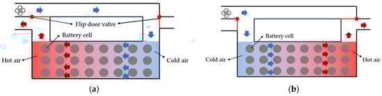
Figure 6.
Reciprocating cooling system concept: (a) flow direction from right to left; (b) flow direction from left to right.
As shown in Figure 7, in their study, Na et al. [65] introduced the Reverse Layered Air Flow (RLAF) method as a way to improve the consistency of the temperature in lithium-ion battery packs. The cooling flow field is divided into multiple layers horizontally, causing adjacent channels to flow in opposite directions and exchange heat through partitions. This improves heat dissipation efficiency and reduces temperature differences, and it has been shown to significantly decrease both the maximum temperature and the temperature difference compared to unidirectional airflow, as confirmed by both CFD simulations and experimental data. Adding a rectifier grid further reduces temperatures by up to 0.5 °C, achieving a 54.5% reduction. The study also optimized cell spacing and inlet velocity, providing guidance for thermal management designs.
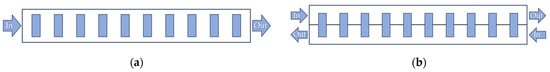
Figure 7.
Schematic diagrams: (a) UDAF; (b) RLAF.
Wang et al. [66] explored methods to enhance the heat dissipation of oversized lithium-ion batteries through the use of alternating airflow. They found that reversing the airflow at 50% discharge depth, at a 3C rate, optimized temperature uniformity. The optimized reversal strategy reduced the temperature inhomogeneity caused by heat accumulation. A novel thermal management strategy combining direct evaporative cooling (DEC) and a reciprocating airflow for improving the temperature uniformity of lithium-ion battery packs was proposed by Zhao et al. [67]. The results indicate that the reciprocating airflow design effectively reduces the thermal accumulation within the battery pack by periodically redistributing the heat, thereby enhancing temperature uniformity.
4.3. Influence of the Cooling Channel Structure
The design of the cooling channels impacts how effectively the system cools, with the pressure drop between battery modules playing a significant role. Optimizing the cooling channel design can effectively lower the maximum temperature of the module without altering the battery pack’s size, decreasing the temperature gap between the battery cells, and reducing the overall system’s power consumption. As shown in Figure 8, there are three main cooling channel structures: Z-type, U-type, and J-type.
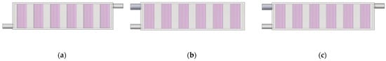
Figure 8.
Schematic of different airflow configurations: (a) Z-type; (b) U-type; (c) J-type.
A new battery pack structure in the shape of a Z was suggested by Xi et al. [68] for the use of large, laminated lithium-ion batteries in new energy vehicles’ optimized air cooling, improving cooling with deflector spoilers and rounded chamfers. Spoilers redirect airflow, enhancing heat transfer. Rounded chamfers reduce turbulence and dead space, improving hot air distribution. An optimized Z-shape structure with 60° spoiler tilt and a 5 mm radius chamfer reduces the maximum temperature, variance, and unevenness. Wang et al. [69] combined a CFD simulation and MOGA to optimize the parameters, such as morphology, number, and length of spoilers, in Z-type battery packs. The effects of three different shapes of spoilers, straight, parabolic, and curved, on the maximum temperature (Max T) and temperature variance of the battery module were investigated. The findings indicate that the flat spoiler is more effective than other designs in terms of cooling efficiency. Following optimization, the maximum temperature of the battery module decreased from 309.82 K to 307.58 K, the temperature variance decreased from 11.85 K to 9.40 K, and the BTMS volume decreased by 4.87%. The optimized design of the spoiler significantly improves the thermal performance. The impact of varying the quantity and size of secondary air openings on the Z-channel and spacer on the cooling efficiency of the BTMS was studied by Zhang et al. [70], who then conducted experimental validation. The BTMS cools best with six secondary air outlets, cutting the maximum temperature by 2.81% and the temperature difference by 51.07% vs. the Z-type. Overall, the maximum temperature is down 4.20% and the temperature difference is down 75%, improving heat dissipation and temperature uniformity and boosting battery pack performance and lifespan.
Chen et al. [71] enhanced the system’s cooling efficiency through structural optimization of a parallel air-cooled BTMS utilizing U-shaped airflow. A flow resistance model calculated airflow in cooling channels, optimized via nested loops and numeric methods. Adjusting the inlet/outlet width reduced the cell temperature difference by 70% at 5C while cutting power consumption by 32%. A new J-type air-cooled BTMS was suggested by Liu et al. [72], combining the benefits of U-type and Z-type designs to enhance the system’s thermal management capabilities. The J-type BTMS demonstrates exceptional versatility and adjustability. Its two outlets with valves optimize cooling in real time. Optimization shows it reduces the temperature rise by 35.3%, 46.6%, and 31.18% vs. U-type and Z-type. Further study shows that J-type’s advantages and manifold optimization adapt to changing conditions, satisfying cooling demands. Experiments verify model accuracy, highlighting J-type’s improved temperature uniformity and lower energy consumption at high heat rates. Luo et al. [73] developed an X-type symmetrical air-cooled BTMS with dual inlets and outlets, enhancing performance by reducing maximum temperatures, temperature differences, and power dissipation by 4.33 K, 74%, and 62.9%, respectively, over conventional designs.
4.4. Thermal Conductivity Enhancement Methods
Another way to adjust channel configurations to optimize performance is to adopt strategies to enhance thermal conductivity within the battery pack, such as combining porous foam aluminum and pin heatsinks. This approach can directly target the thermal needs of the battery pack and improve overall thermal management efficiency. Porous foam aluminum, being an effective heat transfer material, has the potential to enhance the thermal regulation of air-cooled lithium-ion batteries. Insights were given on how embedding aluminum porous metal foam in air-cooled lithium-ion battery module runners affects thermal management performance using three-dimensional transient numerical simulations by Mohamadian et al. [74]. Embedding aluminum porous foam in flow channels boosts cell thermal management, reducing temperature variance and the maximum temperature. Lower porosity cuts the standard deviation of the temperature field and the maximum temperature, while higher permeability lowers the maximum temperature but aids temperature uniformity. The optimization of porosity and pore density in open-cell aluminum foams was investigated by Saw et al. [75] using CFD simulations to identify the most effective cooling solution based on foam parameters. Porous aluminum foam boosts heat transfer by enhancing fluid turbulence and mixing, lowering the cell temperature and variance. The 10 PPI, 0.918 porosity aluminum foam achieved optimal thermal performance and low flow resistance. A thermal model for battery modules was created by Wang et al. [76] in order to examine the thermal relationships among battery cells and investigate how the thermal performance is impacted by the porosity and pore density of aluminum foam. Aluminum foam cools cells better than pure air, but it raises flow resistance, affecting temperature uniformity. The study optimized airflow, battery layout, and foam shape/size for better temperature consistency.
A method for optimizing thermal management was suggested by Mohammadian et al. [77] for air-cooled lithium-ion battery modules, utilizing a pin-fin heat sink. They analyzed how the performance of cells is impacted by the discharge rate, inlet airflow rate, and inlet air temperature by conducting a three-dimensional transient thermal study on heat sinks with different pin-fin height configurations. The investigation revealed that a heat sink featuring pin-fins that increase in height as the channel width expands not only lowers the average temperature within the cell but also enhances the temperature consistency by decreasing the standard deviation of the temperature distribution within the cell, in contrast to a traditional heat sink with uniformly sized pin-fins. Additionally, an increase in the inlet air temperature narrows the temperature range but raises the maximum temperature of the cell. On the other hand, an increase in the inlet airflow rate initially widens the temperature spread but ultimately reduces it, always contributing to a lower maximum temperature within the cell. Chen et al. [78] examined the temperature distribution and pressure drop in battery packs by comparing the use of a pin-fin channel design and an external fin design in CFD simulations. The study investigated two different heat generation scenarios (500 W and 1500 W) and three different cooling flow rates of 100, 200, and 600 cubic meters per hour for battery packs during normal driving and peak load conditions. The simulation results indicate that the cooling structure using pin fins is capable of meeting the temperature distribution requirements of the battery cells at higher flow rates. The external fin design is able to accommodate the temperature variations of the cells across all flow configurations, generating absolute temperatures that are higher than the thermal management requirements. However, the absolute cell temperature is strongly dependent on the cooling capacity of the external fins or the inlet air temperature. In order to meet the specific temperature needs of the cell, either lower the incoming air temperature or enhance the external fin design to improve heat transfer. Furthermore, the external fin design ideas lead to reduced pressure drops in comparison to the pin-fin cooling ideas in every situation, showcasing decreased airflow resistance.
Researchers use machine learning and topology to optimize the structural design of systems. Machine learning enables computers to learn autonomously in order to analyze and predict data, while topology involves studying the invariant nature of spatial shapes. These methods help researchers delve deeper into finding optimal solutions amidst the complexity of conflicting objectives, which in turn improves system performance. Hence, it is a direction well worth digging into. A method for optimizing the design of battery packs was suggested by Cheng et al. [79], which utilized an agent model and focused on multiple objectives to enhance performance. Research and development are conducted on a novel battery thermal management system (BTMS) that utilizes fins for forced-air cooling. The optimization process is broken down into three areas: thermodynamics, hydrodynamics, and the mechanical structure. The goals are to minimize cell temperature, its variation, and system pressure drop. Lightweight design is also considered. Using a multi-objective genetic algorithm, an optimized BTMS design balancing cooling efficiency, system size, and power consumption is achieved. Compared to the unoptimized model, the optimized design reduced maximum cell temperature and temperature differences by 12.82% and 29.72%, respectively. Internal spacer thermal model optimization reduced the average temperature difference by 47.6%. The study demonstrates the effectiveness of comprehensive, multi-disciplinary optimization in improving BTMS performance. A new method for dissipating heat in battery modules using diamond-shaped fins and a long sleeve was suggested by Li et al. [80], who confirmed its effectiveness by comparing it to the traditional method without fins or sleeves. A model for optimizing multiple objectives was created and improved with a genetic algorithm designed for multiple objectives. In the final study, it was found that the maximum temperature (Tmax) and the maximum temperature difference (ΔTmax) of the battery module were reduced by 1.5 K and 36.79%, respectively, without considering the heat dissipation cost; when the heat dissipation cost was considered, the Tmax and ΔTmax were reduced by 0.69 K and 17.92%, respectively. The optimization outcomes enhance both the cooling efficiency of the battery module and ensure that the cooling expenses remain within the specified range. Shi et al. [81] proposed a cooling fin sandwich structure design for battery modules by developing a simplified finite element model consisting of two pouch cells and cooling fins. Simulations show cooling fins can absorb energy. Six sandwich configurations were studied, focusing on a unidirectional double-shell design. Height did not affect density, and 3 mm was optimal for material use and buckling prevention. Comparing crashworthiness, three deformation modes emerged. USDH and circular core structures reduced peak forces and enhanced energy absorption. Thermal enhancers improved cooling but added weight, an important consideration in practical applications.
The study of the BTMS using air cooling concentrates on enhancing the battery arrangement, designing the airflow structure meticulously, boosting thermal conductivity, and creating effective control methods. The findings indicate that the airflow direction plays a crucial role in determining the highest temperature and temperature consistency of the battery pack, and improving the thermal efficiency of the system is possible by strategically arranging the batteries and designing airflow channels. Subsequently, by introducing advanced control strategies, such as machine learning, the system is able to intelligently adjust the airflow distribution according to the real-time temperature and thermal state of the batteries, thus realizing more accurate and efficient thermal management. Furthermore, due to the necessity of a significant volume of air for cooling the battery cells, air-cooling systems usually need bigger pipes and valves, along with powerful fans to ensure adequate circulation. This not only increases the size and weight of the system, reducing its compactness, but also increases energy consumption and operating costs.
5. Liquid-Cooled BTMS
Compared to air-cooled systems, a liquid-based BTMS can offer superior convective heat transfer coefficients and specific heat capacities, resulting in higher heat transfer efficiencies at lower flow rates. However, the use of liquids may lead to increased costs due to the requirement of extra components [82]. Every coolant is chosen for its distinct viscosity and specific heat capacity, which dictate how well it can absorb heat and the level of mechanical energy needed to move the fluid through the battery pack. The form of the fluid cooling arrangement is shown in Figure 9.
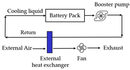
Figure 9.
Schematic of liquid-based BTMS.
Liquid-cooling technologies can be categorized as indirect contact or direct contact. The main difference between the two is that indirect cooling ensures physical separation between the coolant and the lithium-ion battery, thus preventing short circuits, while direct cooling allows for direct contact between the coolant and the battery. Indirect contact liquid cooling uses a pumped circulation system to drive the coolant through the internal channels of liquid-cooling tubes or cold plates on the battery surface, using forced convection heat transfer to dissipate or heat the battery. Direct contact is to immerse the battery pack in the engineered coolant, using the latent heat of the liquid–air phase change of the engineered liquid to absorb the heat of the battery. Immersing the battery pack in the coolant can improve the heat exchange area on the battery surface, with better temperature uniformity; however, there is a risk of leakage of the coolant, and the process requirements and costs are high. To enhance the cooling efficiency and temperature consistency of the liquid cooling system, different enhancement techniques have been suggested, including coolant investigation, channel design optimization, liquid-cooling technology research, and integration with other cooling technologies.
5.1. Direct Cooling
In the field of electric vehicles, liquid battery thermal management systems (BTMSs) typically rely on indirect cooling methods to cope with the high heat load generated by lithium-ion battery packs. In order to accomplish this, fluids with high thermal conductivity and heat capacity, like water–glycol and refrigerants, are utilized. Yet, these liquids possess a notable disadvantage as they conduct electricity, necessitating their separation from the primary heat source, the lithium-ion batteries, with a thermally conductive substance. The system’s complexity is heightened by this isolation, resulting in a larger overall system size.
An emerging and compelling alternative to face this challenge is dielectric immersion cooling, also known as submerged cooling. In this technique, the cell is in direct contact with an electrically insulating working fluid, thus avoiding the need for physical isolation from the heat-conducting fluid. Enhanced contact between the cell and the liquid below increases the surface area for cooling, leading to a remarkably efficient heat transfer and enhancing the battery pack’s cooling performance. This approach not only simplifies the system structure but also promises to reduce the overall system weight, opening up new possibilities for thermal management. In two-phase fluid systems, the latent heat of vaporization boosts convective heat transfer during the liquid–gas transition, with phenomena like nucleation and boiling also contributing to increased turbulent mixing and improved heat dissipation efficiency. In addition, many submerged fluids have the properties of fire-extinguishing agents, which helps to reduce the risk and potential impact of thermal runaway.
The thermophysical characteristics of the coolant play a crucial role in the operational efficiency of the immersion lithium battery thermal management system. Coolant can be classified into five categories, e-fluoride fluid, hydrocarbon, ester, silicone oil, and water-based. Researchers continue to invest their efforts into developing more advanced and efficient immersion fluids. When selecting a coolant, we need to consider a number of aspects in depth to ensure that it meets the needs of the application. The coolant must have a low dielectric constant, good thermal conductivity, and electrical insulation, and it should be stable over the temperature range in which it is used. This is a basic requirement for safe and stable system operation. In addition, we also need to consider the compatibility of the coolant with the lithium battery system materials. The coolant must be non-corrosive with the materials in direct contact to protect the internal components of the system from damage.
Immersion cooling falls under the categories of single-phase cooling and two-phase cooling. During single-phase cooling, the liquid coolant is circulated through a heat exchanger. Two-phase cooling utilizes a low-boiling coolant to vaporize it, which is then condensed back into liquid form using a water condenser unit. The latent heat released during the phase change from liquid to gas in two-phase systems greatly enhances convective heat transfer. Single-phase liquid cooling has a wider range of applications than gas–liquid phase change cooling and is easier to operate experimentally. Gas–liquid phase change cooling involves gas generation and pressure changes, which pose additional challenges for the safe use of mobile platforms, such as automobiles, ships, and aircraft, and require further research and validation.
A direct comparison between immersion cooling and cold-plate-based cooling systems in automotive Li-ion battery modules was presented by Dubey et al. [83]. Using a 21700 cylindrical Li-ion cell with NCA chemistry, its performance was analyzed through CFD methods at various discharge and coolant flow rates. At high discharge rates, immersion cooling achieved lower maximum cell temperatures and gradients due to its higher thermal conductivity. However, the module had higher temperature non-uniformity due to the dielectric fluid’s poorer thermal properties. At low rates, both cooling methods performed similarly. The immersion-cooled unit showed improved performance in coolant pressure drop because of the reduced viscosity and density of the dielectric liquid.
Enhancing the layout and refining the flow path not only enhance the cooling efficiency but also boost the system’s scalability and lower pump power usage. A new cooling channel design was implemented by Tan et al. [84], featuring multiple layers and a crossflow layout to enhance temperature consistency within the battery pack. This design also led to a decrease in the maximum temperature difference and standard deviation by 18.1% and 25.0%, respectively. The research suggests that adjusting the height of the cooling channels can decrease the excess cooling capacity of the system, leading to higher energy density in the battery pack and lower power usage. Le et al. [85] introduced a novel Manifold Immersion Cooling method. By adjusting the cooling channels, it forms a stable wall jet, enhancing heat transfer and reducing surface temperature gradients. The MI structure requires a smaller vortex area for improved heat load and temperature uniformity. Under 5C discharge, the lithium-ion battery pack achieved a maximum temperature of 35.06 °C, reducing volume and surface temperature variations. Ezeiza et al. [86] proposed a modular design for the cooling structure to reduce the impact of the fluid on the overall weight. The system employs a partial cooling strategy, which reduces the quantity of coolant required, thereby reducing the overall weight of the system while increasing the volumetric energy density of the system. Wang et al. [87] suggested a method of direct cooling using immersion coupling. This technology works by immersing the battery in a static medium and arranging direct cooling tubes inside of the pack. Research has demonstrated that the ICDC technology can greatly increase battery life at temperatures below 35 °C by 150.3% and 45.7% compared to natural convection and conventional immersion cooling, respectively, when discharged at a rate of 2C and at an ambient temperature of 25 °C.
Gas–liquid phase change cooling is commonly referred to as boiling cooling. Under high charge/discharge multiplier operating conditions, boiling heat transfer demonstrates excellent temperature control. This feature contributes significantly to the development of lightweight battery systems. Wu et al. [88] proposed an effective boiling cooling system for managing the thermal problems of large soft pack lithium-ion batteries. Using NOVEC 7000 coolant, experiments reveal that in static mode, the system greatly reduces the highest temperature and improves temperature consistency, even during 4C discharge. The intermittent flow mode effectively maintains the battery’s peak and maximum temperature variances under 36 °C and 2 °C, respectively. Wang et al. [89] proposed a novel BTMS using medium HFE-7000 refrigerant and investigated it numerically and experimentally. Forced convective heat transfer with liquid refrigerant effectively controls the cell module’s temperature rise. With an inlet velocity of −0.3 m/s and a discharge temperature of 5C, the maximum cell temperature decreases to 35.10 °C. Temperature uniformity between cells, aided by bubble boiling and two-phase turbulence, maintains a <3.71 °C difference at 5C, 0.1 m/s. Temperature differences are also seen between cells and liquid refrigerant when the temperature drops to 35.10 °C. The numerical and experimental results align well.
5.2. Indirect Cooling
While immersion cooling provides excellent heat dissipation, indirect cooling is easier to implement. Indirect cooling can achieve higher fluid flow rates for the same pumping power due to the lower viscosity of the heat transfer fluid compared to the dielectric fluid used for direct cooling. As a result, indirect cooling has been extensively studied, and this mode of heat exchange is achieved by allowing the fluid to flow through a channel.
The utilization of a water/ethylene glycol mixture as a coolant extends the operational scope of the BTMS, allowing for normal operation in sub-zero-temperature environments. To prevent short-circuit issues resulting from contact between the coolant and the battery following a leak, BTMS systems based on water or a water/ethylene glycol mixture should strictly avoid direct contact between the coolant and the battery. The addition of metallic particles to water to create a nanofluid can enhance the thermal conductivity of the working fluid. Furthermore, liquid metals exhibit superior cooling performance compared to water, effectively reducing energy consumption [90].
5.2.1. Cold Plate
A cold plate, designed mainly for prismatic cells, is a flat plate that contains internal cooling channels. Figure 10 illustrates the three possible positions for the cold plate within the battery pack: inserted in the cell monobloc, clamped onto adjacent cells, or affixed to the battery module’s side. For the design of a cold plate integrated into a battery cell, the dimensions of the channels must be fine-grained to ensure that they can be compactly integrated into the battery structure. Given the complexity of chemical reactions within the battery, the inner walls of these channels must exhibit chemical stability, i.e., remain chemically inert to prevent any potential chemical attack. By embedding cooling plates between neighboring Li-ion cells, we can significantly improve the cooling efficiency of each cell core. However, in order to achieve the efficient performance of the cooling plates, the lithium-ion cells themselves need to be designed thinner. Side cooling panels are usually positioned on the horizontal side or bottom of the battery pack because the top of the battery module is mainly utilized for electrical connections among cells.
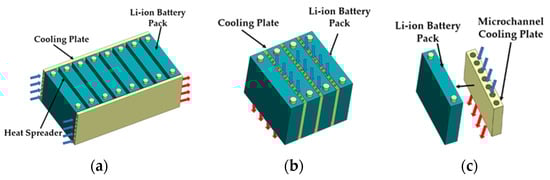
Figure 10.
Insertion position of the cold plate: (a) attached to the side of the battery; (b) clipped onto adjacent batteries; (c) embedded battery cells.
Optimizing the channel configuration within a cold plate can improve its cooling efficiency. Cold plate channel configurations are typically categorized as parallel or serpentine designs. Imran et al. [91] investigated geometry optimization for 3D spiral microchannel heat sinks (SMCHSs). The study proposes four configuration models for SMCHSs and analyzes them through numerical simulations and experimental tests. It is shown that the use of dual inlet and dual outlet spiral configurations can significantly improve the performance of the device compared to the conventional single inlet single outlet spiral. Wang et al. [92] proposed a novel bionic spiderweb-like channel cold plate for improving the cooling effect of the battery. The study explores how a spiderweb-like channel design affects lithium-ion battery cooling at a high 12C discharge rate. Orthogonal experiments show that channel width most impacts cooling, while the angle has the least effect. A 3 mm width and 120 degree angle provide the best thermal balance.
Huo et al. [93] investigated a thermal management system for lithium-ion power batteries based on miniature parallel isometric channel cold plates. The effects of the number of channels, flow direction, inlet mass flow rate, and ambient temperature on the temperature rise and distribution of the battery during discharge were investigated by building a three-dimensional thermal model. Mahmoud et al. [94] compared rectangular microchannel heat sinks with serpentine and parallel cooling channels through numerical and experimental studies. The new designs feature semi-circular and semi-elliptical ribs, along with pinned fins and channels in the sidewalls. The parallel cooling channel design showed inferior thermal performance and lower pressure losses. The combination of fins and channels improved heat dissipation more than just ribs. Energy and turbidity analyses showed improvements of 24% and 37%, respectively. The optimal design is a serpentine structure with multiple inlet/outlet points, circular grooves, and fins, effectively cooling prismatic and pouch lithium-ion batteries. Manufacturability and cost-effectiveness are vital considerations due to the impact on battery pack size. Balancing cooling performance with feasibility and economics is crucial.
5.2.2. Thermally Conductive Tubing
Cooling plates are not suitable for cylindrical lithium-ion batteries because cylindrical batteries lack a flat mounting surface to accommodate cooling plates. To overcome this limitation, heat pipes are an ideal alternative. The conductive tube, filled with liquid coolant, can easily navigate through narrow spaces between cylindrical cells. Its high thermal conductivity allows it to effectively dissipate the heat produced by the lithium-ion battery, ensuring a stable operation and prolonged battery lifespan.
Al-Zareer et al. [95] proposed a novel tube-based cooling system for cylindrical batteries. To cool batteries, they used the heat released from boiling vehicle fuel in an aluminum block tube, preventing direct fuel–battery contact. Simulations compared the system’s performance at 6C and 4C charge–discharge rates to systems using direct cell contact and propane. At 6C, the system cooled poorly. But, at 4C, it kept the battery temperature below 30 °C. It excelled in controlling the maximum battery temperature and inter-cell temperature differences. Liu et al. [32] proposed a novel thermal management system (BTMS) for liquid-cooled batteries, which is based on a combination of vertical layout tubes (VLTs) and a gradient-specific flow rate of the fluid medium as well as a gradient increase in the tube diameter. We examined how pipe diameter and coolant flow rate affect lithium-ion battery cooling. Batteries with vertical tubes performed better than horizontal ones under certain flow rates. Adjusting the flow rate or pipe diameter along a gradient reduced cell temperature differences compared to fixed settings. Combining both strategies improved temperature uniformity even more. The temperature difference of the cell module decreased by 52.16% at −10 °C and by 50.11% at 60 °C. Basu et al. [96] developed a cutting-edge thermal control system for lithium-ion battery packs. The aluminum conductive element wraps around the cylindrical battery for heat conduction and then transfers heat to the coolant. Serving as a barrier in the case of a leak, it stops the coolant from reaching the battery’s electrical components, ultimately enhancing the system’s safety measures. Du et al. [97] developed a mini-channel cooling system for lithium-ion battery modules to manage thermal conditions. Aluminum wraps the cells for heat transfer, and the mini channels circulate around the cylindrical cells. This design reduced energy consumption by 83.2% and 49% at 1C and 1.5C discharge rates while maintaining optimal battery temperatures. However, cells may reach their maximum temperatures at different times during charging and discharging, necessitating a dynamic temperature comparison mechanism.
In a liquid-cooled BTMS, direct cooling facilitates heat transfer by allowing the coolant to come into direct contact with the battery surface. This approach boasts high efficiency in heat transfer capable of rapidly absorbing and conveying the heat generated by the batteries. Direct cooling ensures a more uniform temperature distribution, which is instrumental in enhancing the overall performance and lifespan of the battery pack. Moreover, by eliminating the need for additional heat exchange interfaces, the design can be more compact, making it suitable for applications with space constraints. However, direct cooling also has potential drawbacks, such as the risk of chemical reactions between the coolant and the battery materials, especially in the event of coolant leakage. Additionally, certain coolants may cause corrosion to the battery’s structural materials, increasing the difficulty and cost of system maintenance.
In contrast to direct cooling, indirect cooling separates the coolant from the battery surface using an insulating layer, avoiding potential chemical reactions and corrosion issues, thereby enhancing the system’s chemical compatibility and safety. The design flexibility of indirect cooling is higher, accommodating various layouts and cooling requirements. However, due to the increased thermal resistance, the thermal transfer efficiency of indirect cooling may not match that of direct cooling methods. Furthermore, indirect cooling may lead to non-uniform temperature distribution across the battery surface, particularly during high-power output or rapid charging and discharging processes. Indirect cooling systems may require more complex designs and additional components, which not only increases the system’s cost but also adds to the design complexity.
When selecting a cooling method, it is imperative to consider the specific requirements of the battery system, the chemical properties of the coolant, the cost-effectiveness of the system, the convenience of maintenance, and the overall safety and reliability of the design. Each cooling method has its distinct advantages and limitations, and the final choice is typically dictated by specific application needs and design constraints.
6. Heat Pipes
Heat pipes (HPs) are well-designed, geometrically flexible heat transfer devices that are widely used as efficient thermal management solutions in diverse fields, such as power electronics, cooling systems, and air conditioning systems. As shown in Figure 11, a typical heat pipe structure contains three core components: an evaporator, an adiabatic section, and a condenser. During operation, the evaporator section is connected to a battery system or another heat source to heat and vaporize the heat transfer fluid. The vaporized liquid subsequently moves through the adiabatic segment towards the condenser. In the condensing section, the vapor releases the heat it carries and recondenses to a liquid. Through the capillary force of the wick structure, the condensed liquid is efficiently sucked back to the evaporator, completing the thermal cycle.
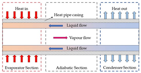
Figure 11.
Schematic diagram of heat pipe.
Jang et al. [98] experimentally evaluated the advantages of a heat-pipe-assisted liquid cooling system over a conventional aluminum plate cooling system in terms of cell temperature control and aging performance under different operating conditions. To achieve the best performance of the heat-pipe-cooled BTMS in BTMS applications, it is necessary to make specific adjustments and optimizations to certain elements of the heat pipe. These elements include the type of heat transfer fluid used, the method of cooling the condenser section, a good heat pipe configuration, and changing the operating conditions and orientation [99]. By precisely controlling and optimizing these elements, it is possible to ensure that the heat pipes provide the maximum thermal management performance in the BTMS.
6.1. Influence of the Working Fluid
The selection of the working medium greatly impacts the efficiency of heat transfer in the heat pipe. Among the many available working fluids, water, acetone, high-carbon alkanes, alcohols, nanofluids, aqueous surfactant solutions, and fluorinated fluids are common choices. Oscillating heat pipes require a working fluid with specific characteristics: low latent heat for quick bubble generation, high specific heat for efficient heat transfer, and low dynamic viscosity and surface tension to enhance fluid flow and heat transfer efficiency. Together, these characteristics ensure the efficient and stable operation of the heat pipe. In the study by Hao et al. [100], experiments explored how polytetrafluoroethylene (PTFE) oscillating heat pipes (OHPs) perform with different fluids (water, ethanol, and acetone). At heating powers from 60 to 300 watts, acetone delivered the highest heat transfer coefficient and lowest thermal resistance. Acetone’s high vapor pressure and low viscosity gave it the best thermal performance. Water, however, performed worse than ethanol and acetone due to its high contact angle and capillary resistance on PTFE.
Mixing metallic or carbon nanoparticles into a fluid boosts its thermal conductivity due to the nanoparticles’ Brownian motion and large surface area. This improves heat transfer efficiency, enhancing performance in heat exchange applications. In their numerical studies, Nasir et al. [101] investigated the application of Al2O3 nanofluid in heat pipes to regulate the temperature of lithium-ion batteries. The findings indicate that employing a 1.5% volume concentration of Al2O3 in the heat pipe as the working fluid can lower the cell surface temperature and total thermal resistance by up to 7.28% and 15%, respectively. Chen et al. [102] examined a thermal control system utilizing a pulsating heat pipe (PHP) filled with TiO2 nanofluids. The battery discharged continuously at 35 °C, and the 1C rate had a maximum temperature of 42.22 °C and a surface gradient of less than 2 °C. Its surface temperature distribution was more uniform, improving by 60%. The lithium-ion battery exhibited satisfactory performance in the maximum temperature, surface gradient, and temperature increase at discharge rates of 0.5C, 1C, and 1.5C. Zhou et al. [103] developed a hybrid vibrating heat pipe (OHP) using carbon nanotube nanofluids for a lithium battery cooling scheme. Using CNT nanofluid in vertical OHP improved startup and heat transfer compared to ethanol–water. By incorporating 0.2% carbon nanotubes (CNTs), the average evaporator temperature and thermal resistance of OHP decreased to 43.1 °C and 0.066 °C/W, outperforming ethanol–water by 9.8 °C and 0.278 °C/W. Battery packs’ average temperature stayed under 45 °C, and the temperature difference stayed below 1 °C.
6.2. Influence of the Cooling Method
Efficient cooling of the condenser is crucial in heat pipe battery thermal management systems. Extended surface design significantly increases the heat exchange area and is a key technology for improving heat transfer efficiency [102]. The air, as a common cooling medium, is assisted by the fan, which effectively removes heat from the surface of the fins, ensuring stable and efficient operation of the condenser.
Behi et al. [104] proposed a heat pipe design where the battery is sandwiched between heat pipes to boost the contact area and heat transfer. Tests showed that the sandwich heat pipe system reduced the maximum cell temperatures by 13.7% to 33.4%, depending on the cooling method used, compared to natural convection. Zhao et al. [105] developed a thermal regulation system for lithium-ion batteries by integrating heat pipes with liquid cooling. After comparing different cooling techniques, they discovered that the system utilizing heat pipes and wet cooling was most effective in regulating temperature increases and reducing gradients when discharging. When the battery pack hit 30 °C, the wet cooling system sprayed water to swiftly lower temperatures back to their initial level. Wang et al. [106] tested a heat pipe cooling system using ethylene glycol solution. It performed well under extreme battery conditions, bringing temperatures below 70 °C. The heat pipe responded quickly even after long low-temperature exposure, showing little impact from cold conditions. Yue et al. [107] created a hybrid BTMS with micro heat pipes, convective air, and intermittent water spray. Heat pipes are utilized by this system to efficiently transfer heat away from the battery, convective air is used during regular operation, and water spray is employed for high-power situations. Tests showed that it reduced the maximum temperature of a 75 Ah Li-ion battery to 29.6 °C and temperature differences to 1.6 °C, down 21% and 57% from no water spray. The system uses just 4.9 wh of energy or 1.8% of the battery’s total capacity.
6.3. Structure Optimizations
Enhancing the cooling efficiency of a heat-pipe-based BTMS often involves utilizing structural optimizations. As shown in Figure 12, Ling et al. [108] created a 3D blade-like heat pipe inspired by nature. Tests showed it controlled device temperatures below 100 °C, 35 °C cooler than standard air cooling. Thermal resistance was reduced by up to 36.3%. Kang et al. [109] designed a pulsating heat pipe with an internal dividing wall to alter liquid and vapor flow, improving heat pipe performance. Tests showed optimal performance at a 70% fill ratio, a 14% improvement over traditional designs. Middle channel walls had the highest thermal conductivity, while inner walls worked best at 30 and 50% fill ratios.
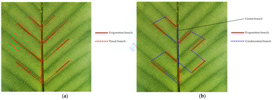
Figure 12.
Design and constructal law of the blade-shaped three-dimensional oscillating heat pipe (LSOHP): (a) design thought of an LSOHP (top view); (b) constructal law of an LSOHP (top view).
6.4. Effect of Heat Pipe Configuration
Due to the variable nature of real-world application scenarios, such as electric vehicles, heat pipe tilting is an unavoidable phenomenon. In order to ensure the efficient operation of a heat-pipe-based BTMS at all angles, it is important to evaluate the performance of heat pipes at different inclination angles. Chi et al. [110] tested oscillating heat pipes at various angles. The OHP worked best within 1–5° angles. Bigger angles led to more internal oscillations, higher thermal resistance, and more power in the low-frequency range. This shows that the OHP performs best when upright. Zhao et al. [111] studied how the angle affects a closed-loop oscillating heat pipe with a PCM. At 0°, it had trouble oscillating continuously, but more heat made it oscillate more. As the angle increased, thermal resistance dropped sharply and then stayed the same. The angle’s effect on resistance lessened with more heat.
For flexible heat pipes, the bending angle affects their thermal performance. Qu et al. [112] studied how bending affects flexible oscillating heat pipes. Bending the adiabatic section changes the fluid flow, raising local resistance and pressure loss. Less bending radius means more loss. Gravity helps the fluid move from condenser to evaporator, but horizontal or upward bending weakens this, reducing heat transfer efficiency.
In the realm of thermal management solutions for lithium-ion batteries, heat pipes stand out as an efficient heat transfer technology with distinctive advantages and limitations. They exhibit exceptional performance in terms of rapid response and high heat flux transfer capabilities. Capable of providing uniform heat dissipation within a compact space, heat pipes contribute to maintaining temperature uniformity across batteries, thereby extending their service life and enhancing performance.
However, the application of heat pipe systems is not without drawbacks. Firstly, the relatively high manufacturing cost of heat pipes could limit their widespread adoption in large-scale applications. Secondly, stringent maintenance requirements are necessary, particularly in terms of cleanliness and the prevention of working fluid leakage. Additionally, the thermal transfer efficiency of heat pipes can be influenced by the internal structure and material selection, necessitating careful consideration and optimization during the design phase. Despite these challenges, heat pipes remain a promising solution for compact and efficient thermal management in the field of battery thermal management.
7. Phase Change Materials
Phase change materials, due to their high latent heat capacity, allow PCM-based BTMS systems to absorb or release significant amounts of heat within a consistent temperature range without requiring active energy-consuming elements like fans or pumps [113]. This improves the effectiveness of PCM-powered BTMS systems, preventing unnecessary power consumption from the battery pack in comparison to air- and liquid-powered BTMS systems, leading to increased energy efficiency. The excellent thermal regulation potential of this mechanism ensures the stable operation of the battery system within the desired temperature range [114]. The phase change processes of latent heat thermal energy storage (LHTES) technology cover a wide range of transformations from solid to solid, liquid to solid, and solid to gas [115]. Among them, the solid–liquid phase transition is particularly prominent, as it exhibits several significant thermophysical advantages [116]. There are some limitations of PCMs in direct application, such as toxicity, risk of leakage, and low thermal conductivity [117]. Encapsulation techniques solve these problems by encapsulating PCMs in robust and performance-enhancing materials [118].
In the realm of PCMs, two primary categories exist: organic and inorganic. Organic PCMs are frequently utilized due to their lower cost, comprehensive melting temperature range, chemical thermal stability, and intermediate phase change enthalpy. However, the flammability of organic constituents poses a significant fire risk, with the potential to exacerbate the danger of thermal runaway and accelerate its propagation [119]. Additionally, the lower viscosity of organic PCMs increases the risk of leakage through containment vessels during phase transition [120].
In contrast to the combustible nature of organics, inorganic PCMs, which encompass hydrated salts, molten salts, metals, and alloys, exhibit inherent non-flammability [121]. Hydrated salts, in particular, demonstrate substantial potential for the thermal management of battery systems due to their suitable phase change temperatures and high latent heat. Nonetheless, the practical application of hydrated salts is severely constrained by drawbacks, such as dehydration, supercooling, and evaporation [122]. Consequently, various enhancement techniques have been implemented to address these limitations. For instance, researchers have mitigated water evaporation at elevated temperatures by utilizing expanded graphite [123] as a skeletal support for the inorganic PCM, coupled with a layer of tin foil and sealant [124].
7.1. Enhanced Thermal Conductivity
Numerous techniques exist to improve the heat transfer capabilities of organic phase change materials (PCMs), including adding fins, encapsulating, and incorporating thermally conductive fillers like carbon-based additives, metal additives, and nanomaterials [125]. These strategies aim to improve the thermal conduction performance of the PCM and thus optimize its thermal management efficiency [126].
7.1.1. Finning
The installation of fins on organic phase change material (PCM) vessels has proven to be an effective strategy to significantly improve heat transfer efficiency. The central advantage of this approach is that the introduction of fins significantly increases the heat transfer surface area, which significantly enhances heat transfer and free convection heat transfer [127]. The design is also favored for its simplicity of construction and low manufacturing costs. In addition, the design is not only easy to implement but also favored for its simplified structure and low manufacturing cost. Two main fin-mounting strategies exist to optimize the heat transfer performance of organic phase change materials (PCMs). Embedding the fins directly into the PCM compound is a strategy that ensures direct contact between the fins and the PCM, leading to a reduction in thermal resistance and a significant improvement in heat transfer efficiency [128]. An alternative approach involves attaching fins to the external surface of the PCM in order to achieve passive cooling of the PCM by facilitating heat transfer between the fins and the ambient surroundings. Both methods have their own advantages and are suitable for different application scenarios. The thermal conductivity of fins is also affected by the number, size, location, and structural design [126].
It is generally accepted that increasing the number of fins enhances the conduction rate of a PCM module. However, this enhancement is also accompanied by a reduction in the volume of the PCM in the PCM module, which in turn limits its thermal storage capacity. In order to find a balance between the conduction rate and the thermal storage capacity, many studies have concluded that PCM modules with four fins exhibit the best overall performance. Weng et al. [129] studied how fins impact PCM module heat performance. Longitudinal fins aid in heat dissipation and enhance convection, whereas circular fins exhibit superior heat transfer capabilities as a result of their increased surface area. An optimized module was tested, featuring four rectangular fins on the top and two circular fins on the bottom. This module reached a maximum temperature of 29.1 °C at a 1C charge rate, 5.5% cooler than a rectangular fin module. The impact of different fin designs, including rectangular, triangular, trapezoidal, I-shaped, and T-shaped, on PCM modules was analyzed by Choudhari et al. [130]. The results show that among all of the fin configurations, I-beam fins have the highest efficiency, and triangular fins have the lowest efficiency considering the temperature difference. Zhang et al. [131] designed a new battery cooling system using a special phase change material. Fins were added to and between liquid cooling channels to improve heat dissipation and control temperatures. Different material combinations had big impacts on cooling. Liquid cooling lowered maximum temperatures but increased temperature differences. With smart fin design, the battery temperature can be lowered, and temperature uniformity can be improved.
The impact of the arrangement and size of fins on the thermal performance of battery modules was studied by Fan et al. [132]. The findings indicate that modifying the arrangement of the fins results in a more uniform heat transfer system, extending the safe operating time by as much as 15.2 percent. Increasing the fin length from 7.5 mm to 13.5 mm resulted in an 8.3 percent improvement in the operating time. Zheng et al. [133] investigated the effect of the geometrical parameters of fins, including thickness, length, and the number of fins, and materials, including nylon, titanium, steel, aluminum alloy, and copper, on the thermal performance through simulation. The findings indicated that the aluminum fins, which were 7.5 mm long and 0.5 mm thick, outperformed those made of other materials. Choudhari et al. [134] tested four fin designs on 5 × 5 Li-ion battery modules. At high discharge, heat builds up inside due to mutual heating and poor PCM conductivity. The center 3 × 3 cell fin design (Type III) best reduced the internal heat. Fins had less effect at low convection but lowered the maximum temperature by 8.17% at high convection.
7.1.2. Incorporation of Thermally Conductive Additives
Improving the heat transfer capabilities of PCMs is primarily achieved through incorporating thermally conductive additives, like nanoparticles, metal particles, metal foams, and carbon nanotubes. The introduction of these fillers significantly enhances the thermal conductivity and efficiency of PCMs and effectively reduces the flammability risk of organic PCMs. Carbon-based materials are now considered excellent hosts for phase change materials with low thermal conductivity, such as paraffin and fatty acids, because of their superior thermal conductivity [135]. Carbon matrices can present diverse geometries, such as tubular, planar, spherical, and other configurations, and these different shapes of carbon matrices provide a wealth of choices and potential combinations for PCMs, which significantly affect the heat transfer characteristics of PCMs [136]. As shown in Figure 13, Wu et al. [137] built a 3D model integrated with the PCM for three cases, studying how the shape of the PCM affects battery cooling. They found that a thicker PCM improves cooling, but this effect weakens after a certain thickness. There is a limit on PCM thickness and convective heat transfer, and a PCM thicker than 2.08 mm is enough. Zhang et al. [138] developed a system for managing heat using materials that change phases. To reduce heat resistance at interfaces, they used a graphene solution. This formed a “battery-graphene-cold plate-graphene-phase change material” unit. When this graphene coating was applied, the battery’s external and internal temperatures fell by up to 7.8% and 7.3%, respectively, during high discharge rates.
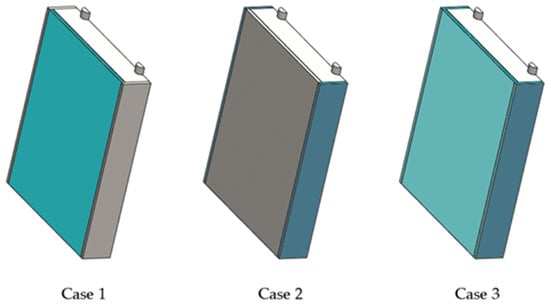
Figure 13.
Three differently shaped PCM configurations.
Metal foam, a unique metal material containing foam-like voids, exhibits notably increased thermal conductivity. Numerous studies have explored how parameters like porosity [139] and pore size [140,141] impact the heat transfer efficiency and latent heat of metal foams. Heyhat et al. [142] improved the TMS performance by adding nanoparticles, metal foams, and fins near the PCM. They used models to simulate nano-PCM melting in porous media. Metal foam was most effective, especially with the same copper volume. Fins helped transfer heat and reduced the melting time. Nanoparticles improved conductivity but may not work well after the PCM melts due to aggregation issues.
The use of nanomaterials, particularly oxide, carbon, and metallic ones, has created a new and promising way to improve the thermal conductivity of PCMs [143]. A study was conducted to analyze a cylindrical thermal energy storage system with a cooling design that includes a phase change material, nanoparticles, and horizontal radial copper fins by Sepehr Mousavi et al. [144]. The results show that using only phase change materials containing 5% of nanoparticles improves the melting time by 5.5%. The optimal outcome is achieved by utilizing nanoparticle PCMs and three fins simultaneously, resulting in a 28.3% reduction in melting time. A novel battery thermal management system was implemented by Jilte et al. [145], utilizing nano-enhanced phase change materials to regulate the temperature of lithium-ion batteries in electric cars. The 7 × 7 × 1 design performed best between 30 °C and 40 °C, keeping the battery temperature below 46 °C, even at 40 °C. Adding nanoparticles increased the thermal conductivity and improved the battery response. However, this may increase the cost and weight and pose thermal stability and environmental risks. Some researchers have mixed metals and carbon to create new PCM materials. Wang et al. [146] developed a novel fireproof composite phase change material for regulating the temperature of lithium-ion batteries. This material combines polyvinyl alcohol, expanded graphite, MXene, melamine polyphosphate, and zinc tin hydroxide. MXene enhanced its phase transition and thermal conductivity, while the flame retardants raised the carbon content, resulting in a V0 rating. In 3C discharge, it cooled the battery, reducing its maximum temperature to 57.03 °C, with a 5 °C temperature difference.
7.2. Hybrid Cooling Method Based on PCMs
Phase change materials, as a passive cooling method, are well-suited for coupling with other cooling methods due to their low demand for energy consumption. Mehrabi-Kermani M et al. [147] studied a new HTMS for lithium-ion battery modules under high pressure. Tests showed that at wind speeds of 3.2 km/h, temperatures during fast discharge stay below 60 °C. Copper foam’s high thermal conductivity helps heat transfer and uniform temperatures. HTMS utilizes a greater amount of heat sink and PCMs’ latent heat capacity compared to other systems when experiencing high current discharge and thermal runaway. Chen G et al. [148] developed a thermal regulation system for lithium-ion batteries utilizing phase change material, metal fins, and air cooling. The fins move through the PCM to create forced convection when it melts. Experiments indicated that this particular design effectively regulates the temperatures of cell surfaces to 25 °C, 32 °C, and 40 °C, resulting in a decrease of 19.8%, 18.9%, and 18.6%, respectively, when compared to cells without protection. The temperature variance on the cell surface was notably decreased to 2.3 °C, 2.2 °C, and 1.9 °C, all falling under the standard 5 °C requirement.
As shown in Figure 14, a BTMS was suggested by Jilte et al. [149] that integrates a phase change material (PCM) with an enhanced inter-cell air cooling method. Inter-cell air cooling was achieved by dividing the battery pack into multiple modules, each containing six cylindrical cells arranged in a 1S6P arrangement with a 4 mm cylindrical gap around each cell filled with a PCM. The findings from the experiment indicate that this configuration is successful in enhancing the evenness of the temperature in the battery unit when discharging at rates of 2C and 4C and at temperatures of 27 °C, 35 °C, and 40 °C, while also managing to limit the temperature increase to within 5 °C. This structure not only realizes air cooling between cells but also reduces the amount of PCM to a certain extent, thereby reducing the cost and weight.
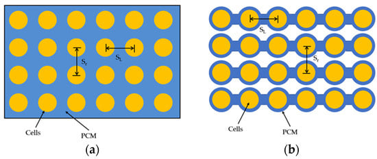
Figure 14.
PCM layout before and after improvements: (a) before optimization; (b) after optimization.
As shown in Figure 15, a hybrid BTMS was suggested by Qin et al. [150] that combined forced-air convection with a PCM, and its effectiveness was confirmed through experimentation. It was shown that the thermal performance in the active mode was significantly better than that in the passive mode. At a multiplicity of 3C compared to the passive mode, the maximum temperature difference and maximum temperature in active mode decreased by 1.2 °C and 16 °C, respectively. In addition, a mathematical model based on a 3D heat transfer model and an electrochemical model was developed and validated with experimental data. Taking advantage of the mathematical model, the space of the designed structure was further optimized, and an inter-cell gap of 5 mm was recommended.
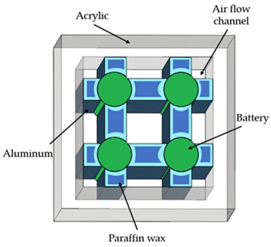
Figure 15.
Schematic diagram of the structure combining forced-air convection and a PCM.
Liquid cooling requires a lot of energy because it has to handle heavy workloads and operate for extended periods of time. By combining it with a PCM, it is possible to address the drawbacks of liquid cooling while also taking advantage of the benefits of both approaches. A combination of phase change material and liquid cooling was suggested by Chen et al. [151] to maintain consistent high temperatures in an eight-cell prismatic battery module during fast charging. Experiments indicate that achieving the best thermal performance does not solely depend on the highest coolant flow rate or the maximum thickness of the phase change material. At a thickness of 0.65 mm for the phase change material and a coolant flow rate of 54 mL/min, the hybrid cooling system demonstrates peak thermal efficiency during 3C rapid charging, leading to decreased energy and volume usage. Researchers led by An [152] have devised a novel, cellular hybrid BTMS that leverages 3D printing to amalgamate water cooling with the CPCM. This system features an integrated heating element within the water channel assembly, endowing it with capabilities for both thermal regulation and compact design modularity. Pakrouh et al. [153] examined a liquid cooling BTMS leveraging the TEC and PCM, where PCMs serve as a passive cooling technique to minimize energy usage while regulating TEC surface temperatures. Kong et al. [154] created a BTMS that integrates the PCM and controlled liquid cooling to regulate the temperature of lithium-ion battery packs in varying environmental conditions. Simulations and experiments confirmed the system’s thermal efficiency when discharged at 3C and charged at 0.5C. The tests demonstrate the system’s ability to efficiently regulate the battery pack’s maximum surface temperature and temperature variance to 41.1 °C and 4 °C, respectively, in temperatures up to 30 °C. At the same time, the PCM’s latent heat is recovered by the system while charging at a rate of 0.5C. By monitoring the PCM and ambient temperature, adjusting the coolant flow rate can enhance the battery pack’s thermal efficiency across various temperatures and decrease liquid cooling power usage significantly. A study by Wang et al. [155] introduces an innovative BTMS that integrates the CPCM with liquid cooling, enhancing heat dissipation efficiency. The CPCM, formulated with paraffin wax, EG, and copper nanoparticles, mitigates leakage issues and boosts thermal conductivity. The system’s performance was validated through an automated temperature control framework, demonstrating superior temperature uniformity and regulation compared to traditional cooling approaches.
A new honeycomb-shaped BTMS for controlling the temperature of cylindrical Li-ion batteries was developed by integrating bionic liquid microchannels and PCMs by Yang et al. [156]. A neural network employing back-propagation was utilized to predict the correct flow rate at the inlet by considering the driving cycle circumstances and the surrounding temperature. The predictions made using the BP model helped maintain the battery module’s maximum temperature and temperature difference within 312.0 K and 3.5 K after a period of variability. Zhang et al. [157] optimized the heat transfer path in order to prevent thermal runaway propagation by incorporating aluminum plates between the PCM sheets of adjacent cells and connecting them to water-cooling channels. Figure 16 illustrates how this particular design utilizes the latent heat of the phase change from the PCM to regulate the battery temperature during regular operation. In instances of thermal runaway or when substantial heat dissipation is needed, the PCM serves as a thermal buffer and triggers the water-cooling system to prevent the spread of thermal runaway. The suggested system demonstrates the ability to efficiently address the issue of declining performance in a traditional PCM-based BTMS during cycling conditions caused by the saturation of the PCM’s heat absorption.
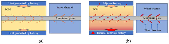
Figure 16.
Hybrid BTMS schematic: (a) normal working condition; (b) thermal runaway working condition.
Qu et al. [158] examined the heat transfer efficiency of a thermal control system that integrates phase change substances with 3D vibrating heat pipes. A four-layer 3DOHP and a three-layer 3DOHP combined with a PCM were designed and experimentally compared with several 2D-OHP combined PCM systems. The findings indicate that the 3DOHP system demonstrates superior thermal efficiency compared to the 2D-OHP system in both melting and solidifying processes. A new thermal management system combining heat pipes and phase change materials was suggested for 55 Ah lithium-ion battery packs by Leng et al. [159]. A multi-objective optimization was performed to minimize the thickness of the PCM and the power of the fan at a charge/discharge rate of 5C. Active–passive thermal management achieved an 81.80% maximum energy saving according to the results. A 3D numerical model was created by Peng et al. [160] in order to simulate and validate a unique system that combines the phase change material (PCM) and heat pipes, which was specifically developed for the purpose of managing the temperature of cylindrical lithium-ion battery modules. The findings from the simulation indicate that the composite PCM with 12 wt% expanded graphite (EG) exhibits superior thermal diffusion capabilities compared to a pure PCM. Additionally, reducing the discharge C-rate and extending the recovery time can enhance the thermal efficiency of the battery module. The innovative aspect of the study by Liu et al. [7] lies in the design and analysis of a novel thermal management system for Li-ion batteries that integrates an annular thermoelectric cooler and the PCM, optimizing battery temperature control during both normal operation and abnormal heat-generation events to effectively suppress thermal runaway.
By combining the active cooling system’s effective heat dissipation with the passive cooling system’s consistent stability, the active component rapidly eliminates extra heat to prevent overheating and sustain optimal operating temperatures in demanding situations like rapid charging or intense driving; at the same time, the passive system absorbs and releases heat as needed to ensure ongoing thermal regulation for the battery. During times of low usage or when the device is on standby, the active cooling elements adapt to lower energy usage, while passive cooling ensures the battery’s temperature stays within acceptable levels. This integration ensures that the BTMS maintains efficient performance under a variety of load conditions.
Phase-change-material-based battery thermal management systems are recognized for their proficiency in temperature regulation and safety enhancement, attributable to their capacity to absorb considerable thermal energy during phase transitions. These systems present an economical and readily integrable solution. Nonetheless, the heat extraction efficacy of PCM systems is contingent upon the mass of the PCM, which may necessitate the adoption of heavier and more substantial system designs to facilitate complete heat dissipation.
The judicious selection of the PCM is pivotal for the development of an efficient BTMS. This selection demands a meticulous assessment of several key parameters, including the operational temperature range, the phase transition temperature, the latent heat capacity, and thermal conductivity. It is also essential to scrutinize the thermophysical properties of the materials, with a particular focus on mitigating supercooling phenomena and accommodating volumetric changes that occur during phase transitions.
Augmenting the thermal conductivity of PCMs stands as a critical strategy for ameliorating their performance. This enhancement can be realized through the incorporation of fin structures, the application of encapsulation techniques, and the integration of high-thermal-conductivity fillers. Such methodologies are conducive to refining the thermal management system’s efficiency.
8. Summary and Outlook
Lithium-ion batteries’ thermal safety relies on effective BTMSs to maintain the ideal operating temperatures. A comprehensive understanding of BTMS development should consider their various types and their respective strengths and weaknesses, as outlined in Table 1.

Table 1.
Comparison of different types of BTMSs.
Air and liquid preheating methods are favored for their ease of use and efficiency, respectively. PCMs and heat pipe preheating offer integrated solutions to reduce energy consumption. While electric heating films provide a rapid temperature rise and good uniformity, their safety and reliability remain concerns, necessitating power limitations to prevent overheating. In the realm of battery pack cooling, heat pipes and PCMs provide superior performance but with higher energy use and costs. Liquid-based BTMSs offer a cost-effective solution with slightly reduced efficiency. Air and PCM systems are more reliable, while heat pipes and passive liquids are moderately so. Heat-pipe- and PCM-based BTMSs are compact and lightweight, enhancing their portability. Air-cooled BTMSs, with a lower cost and simpler structure, are limited by the air’s low heat capacity and transfer coefficient, affecting its heat dissipation capabilities. Research on air delivery methods and cell arrangements is crucial in optimizing the airflow direction and temperature consistency within battery packs. Liquid cooling systems excel in heat dissipation due to their efficiency and uniformity, with immersion cooling standing out for the management of heavily loaded packs. However, they require more components, increasing the power consumption, weight, and complexity. The development of new, efficient coolants and the optimization of cooling systems are active research areas. Heat-pipe-based BTMSs are small and energy-efficient but may require additional cooling techniques for optimal cell cooling, leading to increased spatial requirements and integration challenges. Nanofluids are being explored as alternatives to enhance the heat transfer in heat pipes. The phase-change-material-based BTMS offers effective temperature control and safety, but it can be bulky due to their reliance on mass. The selection of the appropriate PCM is critical for efficient operation, considering factors like the operation temperature, the phase change temperature, the latent heat capacity, and thermal conductivity. Hybrid BTMSs, integrating multiple types, capitalize on the advantages of each, providing efficient heat dissipation and redundancy. However, this increases the system’s complexity and cost. Future research should explore the combined use of technologies and optimization algorithms for a more effective and secure battery thermal control system. The future of BTMSs lies in hybrid cooling with integrated low-temperature preheating, considering the practical operating conditions. Immersed liquid-based BTMSs show the most promise, and research should focus on their optimization. Machine learning and topology optimization are emerging as key areas for the enhancement of BTMS design and control strategies.
The integration of 3D printing with innovative materials is revolutionizing lithium-ion battery thermal management. Materials designed through topology optimization enhance the heat conduction pathways, improving the performance of cooling fins and heat exchangers [161]. Novel cellular structures, such as hydrogel scaffolds, regulate the porosity to facilitate cell infiltration, offering new avenues for thermal management [162,163]. These materials, with high porosity and cell compatibility, are ideal for internal thermal exchange media. The prospective application of these materials in BTMSs is extensive, promising to elevate the battery’s performance and safety through more efficient thermal management solutions.
Author Contributions
Conceptualization, L.X. (Liang Xu) and S.W.; methodology, S.W.; validation, L.X. (Lei Xi); formal analysis, S.W.; investigation, S.W.; resources, L.X. (Liang Xu) and J.G.; data curation, S.W.; writing—original draft preparation, S.W.; writing—review and editing, L.X. (Liang Xu); visualization, S.W.; supervision, Y.L. and L.X. (Lei Xi); project administration, J.G. and Y.L.; funding acquisition, L.X. (Liang Xu) and L.X. (Lei Xi). All authors have read and agreed to the published version of the manuscript.
Funding
This work was funded by the Natural Science Foundation of Shaanxi Province (2024JC-YBMS-345), the Fundamental Research Funds for the Central Universities (xzy022024097), and the China Postdoctoral Science Foundation (2021M702573).
Conflicts of Interest
The authors declare no conflicts of interest.
Nomenclature
| BTMS | Battery thermal management system |
| SEI | Solid electrolyte interface |
| PCM | Phase change material |
| CPCM | Composite phase change material |
| HGR | Heat generation rate |
| BPNN | Back-propagation neural network |
| HTF | Heat transfer fluid |
| ECM | Equivalent circuit model |
| SHLB | Self-heating lithium-ion battery |
| RLAF | Reverse Layered Air Flow |
| DEC | Direct evaporative cooling |
| SMCHS | Spiral microchannel heat sink |
| VLTs | Vertical layout tubes |
| PTFE | Polytetrafluoroethylene |
| OHPs | Oscillating heat pipes |
| PHP | Pulsating heat pipe |
| CNT | Carbon nanotube |
| EG | Expanded graphite |
References
- Chen, J.; Manivanan, M.; Duque, J.; Kollmeyer, P.; Panchal, S.; Gross, O.; Emadi, A. A Convolutional Neural Network for Estimation of Lithium-Ion Battery State-of-Health during Constant Current Operation. In Proceedings of the 2023 IEEE Transportation Electrification Conference & Expo (ITEC), Detroit, MI, USA, 21–23 June 2023; pp. 1–6. [Google Scholar]
- Lin, S.; Zhou, L. Thermal performance of rectangular serpentine mini-channel cooling system on lithium battery. J. Clean. Prod. 2023, 418, 138125. [Google Scholar] [CrossRef]
- Yu, X.; Chen, R.; Gan, L.; Li, H.; Chen, L. Battery Safety: From Lithium-Ion to Solid-State Batteries. Engineering 2023, 21, 9–14. [Google Scholar] [CrossRef]
- Mu, D.; Ren, H.; Wang, C.; Yue, X.; Du, J.; Ghadimi, P. Structural characteristics and disruption ripple effect in a meso-level electric vehicle Lithium-ion battery supply chain network. Resour. Policy 2023, 80, 103225. [Google Scholar] [CrossRef]
- Chen, M.; Song, W.; Lin, S.; Bai, F.; Feng, Z. Risk evaluation of internal short circuit for lithium-ion battery based on an active protection method. Int. J. Energy Res. 2022, 46, 11879–11891. [Google Scholar] [CrossRef]
- Feng, J.; Cai, F.; Li, H.; Huang, K.; Yin, H. A data-driven prediction model for the remaining useful life prediction of lithium-ion batteries. Process Saf. Environ. Prot. 2023, 180, 601–615. [Google Scholar] [CrossRef]
- Liu, X.; Wu, P.-Y.; Su, C.-Q.; Xiong, X.; Wang, Y.-P. Li-ion battery thermal management and thermal runaway suppression method of combining phase change material and annular thermoelectric cooler. J. Energy Storage 2024, 82, 110564. [Google Scholar] [CrossRef]
- Khan, M.M.; Alkhedher, M.; Ramadan, M.; Ghazal, M. Hybrid PCM-based thermal management for lithium-ion batteries: Trends and challenges. J. Energy Storage 2023, 73, 108775. [Google Scholar] [CrossRef]
- Pu, J.; Huang, Z.; Wu, C.; Liu, S.; Liu, S.; Liu, X.; You, L.; Wang, Q.; Zheng, Y.; Zeng, R.; et al. Boosting the performance enhancement of short-process regenerated Ni-rich cathode via antimony doping and modification. Energy Storage Mater. 2024, 67, 103304. [Google Scholar] [CrossRef]
- Liu, X.; Wang, R.H.; Liu, S.Q.; Pu, J.H.; Xie, H.G.; Wu, M.L.; Liu, D.M.; Li, Y.; Liu, J.W. Organic Eutectic Salts-Assisted Direct Lithium Regeneration for Extremely Low State of Health Ni-Rich Cathodes. Adv. Energy Mater. 2023, 13, 2302987. [Google Scholar] [CrossRef]
- Garud, K.S.; Tai, L.D.; Hwang, S.-G.; Nguyen, N.-H.; Lee, M.-Y. A Review of Advanced Cooling Strategies for Battery Thermal Management Systems in Electric Vehicles. Symmetry 2023, 15, 1322. [Google Scholar] [CrossRef]
- Zhao, Y.; Zou, B.; Zhang, T.; Jiang, Z.; Ding, J.; Ding, Y. A comprehensive review of composite phase change material based thermal management system for lithium-ion batteries. Renew. Sustain. Energy Rev. 2022, 167, 112667. [Google Scholar] [CrossRef]
- Hwang, F.S.; Confrey, T.; Reidy, C.; Picovici, D.; Callaghan, D.; Culliton, D.; Nolan, C. Review of battery thermal management systems in electric vehicles. Renew. Sustain. Energy Rev. 2024, 192, 114171. [Google Scholar] [CrossRef]
- Wang, Y.; Zhang, X.; Chen, Z. Low temperature preheating techniques for Lithium-ion batteries: Recent advances and future challenges. Appl. Energy 2022, 313, 118832. [Google Scholar] [CrossRef]
- Liu, J.; Zhou, L.; Zhang, Y.; He, T.; Wang, Z. Thermal stability of lithium-ion battery subjected to inhomogeneous aging. Process Saf. Environ. Prot. 2023, 180, 992–1002. [Google Scholar] [CrossRef]
- Gong, J.; Liu, B.; Lian, H.; Liu, J.; Fu, H.; Miao, Y.; Liu, J. Numerical investigation of suppressing thermal runaway propagation in a lithium-ion battery pack using thermal insulators. Process Saf. Environ. Prot. 2023, 176, 1063–1075. [Google Scholar] [CrossRef]
- Yang, R.; Xie, Y.; Li, K.; Tran, M.K.; Fowler, M.; Panchal, S.; Deng, Z.; Zhang, Y. Comparative Study on the Thermal Characteristics of Solid-State Lithium-Ion Batteries. IEEE Trans. Transp. Electrif. 2024, 10, 1541–1557. [Google Scholar] [CrossRef]
- Vashisht, S.; Rakshit, D.; Panchal, S.; Fowler, M.; Fraser, R. Thermal behaviour of Li-ion battery: An improved electrothermal model considering the effects of depth of discharge and temperature. J. Energy Storage 2023, 70, 107797. [Google Scholar] [CrossRef]
- Ushak, S.; Song, W.; Marin, P.E.; Milian, Y.; Zhao, D.; Grageda, M.; Lin, W.; Chen, M.; Han, Y. A review on phase change materials employed in Li-ion batteries for thermal management systems. Appl. Mater. Today 2024, 37, 102021. [Google Scholar] [CrossRef]
- Chanthevee, P.; Hirai, S.; Lailuck, V.; Laoonual, Y.; Sriam, P.; Rompho, S.; Chanurai, N.; Masomtob, M. A Simplified Approach for Heat Generation Due to Entropy Change in Cylindrical LCO Battery. In Proceedings of the 2018 IEEE Transportation Electrification Conference and Expo, Asia-Pacific (ITEC Asia-Pacific), Bangkok, Thailand, 6–9 June 2018; pp. 1–5. [Google Scholar]
- Wu, C.; Wu, L.; Qiu, C.; Yang, J.; Yuan, X.; Cai, Y.; Shi, H. Experimental and numerical studies on lithium-ion battery heat generation behaviors. Energy Rep. 2023, 9, 5064–5074. [Google Scholar] [CrossRef]
- Rao, Z.; Wang, S.; Wu, M.; Lin, Z.; Li, F. Experimental investigation on thermal management of electric vehicle battery with heat pipe. Energy Convers. Manag. 2013, 65, 92–97. [Google Scholar] [CrossRef]
- Zhang, G.; Wei, X.; Chen, S.; Wei, G.; Zhu, J.; Wang, X.; Han, G.; Dai, H. Research on the impact of high-temperature aging on the thermal safety of lithium-ion batteries. J. Energy Chem. 2023, 87, 378–389. [Google Scholar] [CrossRef]
- Choudhari, V.G.; Dhoble, D.A.S.; Sathe, T.M. A review on effect of heat generation and various thermal management systems for lithium ion battery used for electric vehicle. J. Energy Storage 2020, 32, 101729. [Google Scholar] [CrossRef]
- Burow, D.; Sergeeva, K.; Calles, S.; Schorb, K.; Börger, A.; Roth, C.; Heitjans, P. Inhomogeneous degradation of graphite anodes in automotive lithium ion batteries under low-temperature pulse cycling conditions. J. Power Sources 2016, 307, 806–814. [Google Scholar] [CrossRef]
- Wang, T.; Li, Y.; Zeng, Y.; Zhang, G.; Zhao, G.; Li, X.; Rao, Z. Investigation on the battery thermal management and thermal safety of battery-powered ship with flame-retardant composite phase change materials. J. Energy Storage 2024, 81, 110228. [Google Scholar] [CrossRef]
- Ji, C.; Liu, D.; Liu, Y.; Wang, S.; Wang, Y.; Zhang, Z.; Wang, B. Effect of low temperature and high-rate cyclic aging on thermal characteristics and safety of lithium-ion batteries. Process Saf. Environ. Prot. 2024, 188, 1514–1526. [Google Scholar] [CrossRef]
- Nagasubramanian, G. Electrical characteristics of 18650 Li-ion cells at low temperatures. J. Appl. Electrochem. 2001, 31, 99–104. [Google Scholar] [CrossRef]
- Ouyang, M.; Chu, Z.; Lu, L.; Li, J.; Han, X.; Feng, X.; Liu, G. Low temperature aging mechanism identification and lithium deposition in a large format lithium iron phosphate battery for different charge profiles. J. Power Sources 2015, 286, 309–320. [Google Scholar] [CrossRef]
- Piao, N.; Gao, X.; Yang, H.; Guo, Z.; Hu, G.; Cheng, H.-M.; Li, F. Challenges and development of lithium-ion batteries for low temperature environments. eTransportation 2022, 11, 100145. [Google Scholar] [CrossRef]
- Qin, P.; Sun, J.; Yang, X.; Wang, Q. Battery thermal management system based on the forced-air convection: A review. etransportation 2021, 7, 100097. [Google Scholar] [CrossRef]
- Liu, Z.; Liu, X.; Meng, H.; Guo, L.; Zhang, Z. Numerical analysis of the thermal performance of a liquid cooling battery module based on the gradient ratio flow velocity and gradient increment tube diameter. Int. J. Heat Mass Transf. 2021, 175, 121338. [Google Scholar] [CrossRef]
- Fan, R.J.; Zhang, C.Z.; Wang, Y.; Ji, C.Z.; Meng, Z.Q.; Xu, L.; Ou, Y.; Chin, C.S. Numerical study on the effects of battery heating in cold climate. J. Energy Storage 2019, 26, 100969. [Google Scholar] [CrossRef]
- Wang, Y.; Rao, Z.; Liu, S.; Li, X.; Li, H.; Xiong, R. Evaluating the performance of liquid immersing preheating system for Lithium-ion battery pack. Appl. Therm. Eng. 2021, 190, 116811. [Google Scholar] [CrossRef]
- E, J.; Qin, Y.; Zhang, B.; Yin, H.; Tan, Y. Effects of heating film and phase change material on preheating performance of the lithium-ion battery pack with large capacity under low temperature environment. Energy 2023, 284, 129280. [Google Scholar] [CrossRef]
- Chen, M.; Li, J. Experimental study on heating performance of pure electric vehicle power battery under low temperature environment. Int. J. Heat Mass Transf. 2021, 172, 121191. [Google Scholar] [CrossRef]
- Liang, L.; Zhao, Y.; Diao, Y.; Ren, R.; Zhu, T.; Li, Y. Experimental investigation of preheating performance of lithium-ion battery modules in electric vehicles enhanced by bending flat micro heat pipe array. Appl. Energy 2023, 337, 120896. [Google Scholar] [CrossRef]
- Moria, H.; Pourhedayat, S.; Dizaji, H.S.; Abusorrah, A.M.; Abu-Hamdeh, N.H.; Wae-hayee, M. Exergoeconomic analysis of a Peltier effect air cooler using experimental data. Appl. Therm. Eng. 2021, 186, 116513. [Google Scholar] [CrossRef]
- Zhang, C.; Jin, X.; Li, J. PTC Self-Heating Experiments and Thermal Modeling of Lithium-Ion Battery Pack in Electric Vehicles. Energies 2017, 10, 572. [Google Scholar] [CrossRef]
- Lei, Z.; Zhang, C.; Li, J.; Fan, G.; Lin, Z. Preheating method of lithium-ion batteries in an electric vehicle. J. Mod. Power Syst. Clean Energy 2015, 3, 289–296. [Google Scholar] [CrossRef]
- Yang, W.; Zhou, F.; Liu, Y.; Chen, X. Preheating Performance by Heating Film for the Safe Application of Cylindrical Lithium-ion Battery at Low Temperature. Fire Technol. 2023, 59, 1115–1135. [Google Scholar] [CrossRef]
- Wang, C.-Y.; Zhang, G.; Ge, S.; Xu, T.; Ji, Y.; Yang, X.-G.; Leng, Y. Lithium-ion battery structure that self-heats at low temperatures. Nature 2016, 529, 515–518. [Google Scholar] [CrossRef]
- Lin, C.; Tao, Z.; Tian, Y. Variable duty cycle heating strategy based online two-dimensional model for self-heating lithium-ion battery. J. Energy Storage 2022, 55, 105572. [Google Scholar] [CrossRef]
- Ji, Y.; Wang, C.Y. Heating strategies for Li-ion batteries operated from subzero temperatures. Electrochim. Acta 2013, 107, 664–674. [Google Scholar] [CrossRef]
- Ruan, H.; Jiang, J.; Sun, B.; Su, X.; He, X.; Zhao, K. An optimal internal-heating strategy for lithium-ion batteries at low temperature considering both heating time and lifetime reduction. Appl. Energy 2019, 256, 113797. [Google Scholar] [CrossRef]
- Stuart, T.A.; Hande, A. HEV battery heating using AC currents. J. Power Sources 2004, 129, 368–378. [Google Scholar] [CrossRef]
- Zhu, J.; Sun, Z.; Wei, X.; Dai, H.; Gu, W. Experimental investigations of an AC pulse heating method for vehicular high power lithium-ion batteries at subzero temperatures. J. Power Sources 2017, 367, 145–157. [Google Scholar] [CrossRef]
- Li, J.; Sun, D.; Chai, Z.; Jiang, H.; Sun, C. Sinusoidal alternating current heating strategy and optimization of lithium-ion batteries with a thermo-electric coupled model. Energy 2019, 186, 115798. [Google Scholar] [CrossRef]
- Zhang, L.; Fan, W.; Wang, Z.; Li, W.; Sauer, D.U. Battery heating for lithium-ion batteries based on multi-stage alternative currents. J. Energy Storage 2020, 32, 101885. [Google Scholar] [CrossRef]
- Li, Y.; Gao, X.; Qin, Y.; Du, J.; Guo, D.; Feng, X.; Lu, L.; Han, X.; Ouyang, M. Drive circuitry of an electric vehicle enabling rapid heating of the battery pack at low temperatures. iScience 2021, 24, 101921. [Google Scholar] [CrossRef]
- Zhao, G.; Wang, X.; Negnevitsky, M.; Zhang, H. A review of air-cooling battery thermal management systems for electric and hybrid electric vehicles. J. Power Sources 2021, 501, 230001. [Google Scholar] [CrossRef]
- Chen, K.; Wang, S.; Song, M.; Chen, L. Configuration optimization of battery pack in parallel air-cooled battery thermal management system using an optimization strategy. Appl. Therm. Eng. 2017, 123, 177–186. [Google Scholar] [CrossRef]
- Fan, Y.; Bao, Y.; Ling, C.; Chu, Y.; Tan, X.; Yang, S. Experimental study on the thermal management performance of air cooling for high energy density cylindrical lithium-ion batteries. Appl. Therm. Eng. 2019, 155, 96–109. [Google Scholar] [CrossRef]
- Du, J.; Tao, H.; Chen, Y.; Yuan, X.; Lian, C.; Liu, H. Thermal Management of Air-Cooling Lithium-Ion Battery Pack. Chin. Phys. Lett. 2021, 38, 118201. [Google Scholar] [CrossRef]
- Hai, T.; Abidi, A.; Sajadi, S.M.; Zain, J.M.; Malekshah, E.H.; Aybar, H.Ş. Simultaneous cooling of plate and cylindrical batteries in an air-cooled lithium battery thermal management system, by changing the distances of the batteries from each other and the pack wall. J. Taiwan Inst. Chem. Eng. 2023, 148, 104931. [Google Scholar] [CrossRef]
- Kirad, K.; Chaudhari, M. Design of cell spacing in lithium-ion battery module for improvement in cooling performance of the battery thermal management system. J. Power Sources 2021, 481, 229016. [Google Scholar] [CrossRef]
- Liao, X.; Ma, C.; Peng, X.; Garg, A.; Bao, N. Temperature Distribution Optimization of an Air-Cooling Lithium-Ion Battery Pack in Electric Vehicles Based on the Response Surface Method. J. Electrochem. Energy Convers. Storage 2019, 16, 041002. [Google Scholar] [CrossRef]
- Peng, X.; Ma, C.; Garg, A.; Bao, N.; Liao, X. Thermal performance investigation of an air-cooled lithium-ion battery pack considering the inconsistency of battery cells. Appl. Therm. Eng. 2019, 153, 596–603. [Google Scholar] [CrossRef]
- Wang, Y.-W.; Jiang, J.-M.; Chung, Y.-H.; Chen, W.-C.; Shu, C.-M. Forced-air cooling system for large-scale lithium-ion battery modules during charge and discharge processes. J. Therm. Anal. Calorim. 2019, 135, 2891–2901. [Google Scholar] [CrossRef]
- Pan, S.; Ji, C.; Wang, S.; Wang, B. Study on the Performance of Parallel Air-Cooled Structure and Optimized Design for Lithium-Ion Battery Module. Fire Technol. 2020, 56, 2623–2647. [Google Scholar] [CrossRef]
- Mahamud, R.; Park, C. Reciprocating air flow for Li-ion battery thermal management to improve temperature uniformity. J. Power Sources 2011, 196, 5685–5696. [Google Scholar] [CrossRef]
- Yu, K.; Yang, X.; Cheng, Y.; Li, C. Thermal analysis and two-directional air flow thermal management for lithium-ion battery pack. J. Power Sources 2014, 270, 193–200. [Google Scholar] [CrossRef]
- Wang, C.; Xu, J.; Wang, M.; Xi, H. Experimental investigation on reciprocating air-cooling strategy of battery thermal management system. J. Energy Storage 2023, 58, 106406. [Google Scholar] [CrossRef]
- Wang, H.; Ma, L. Thermal management of a large prismatic battery pack based on reciprocating flow and active control. Int. J. Heat Mass Transf. 2017, 115, 296–303. [Google Scholar] [CrossRef]
- Na, X.; Kang, H.; Wang, T.; Wang, Y. Reverse layered air flow for Li-ion battery thermal management. Appl. Therm. Eng. 2018, 143, 257–262. [Google Scholar] [CrossRef]
- Wang, S.; Li, K.; Tian, Y.; Wang, J.; Wu, Y.; Ji, S. Improved thermal performance of a large laminated lithium-ion power battery by reciprocating air flow. Appl. Therm. Eng. 2019, 152, 445–454. [Google Scholar] [CrossRef]
- Zhao, R.; Liu, J.; Gu, J.; Zhai, L.; Ma, F. Experimental study of a direct evaporative cooling approach for Li-ion battery thermal management. Int. J. Energy Res. 2020, 44, 6660–6673. [Google Scholar] [CrossRef]
- Xi, Y.; Feng, Y.; Xiao, Y.; He, G. Novel Z-Shaped Structure of Lithium-Ion Battery Packs and Optimization for Thermal Management. J. Energy Eng. 2020, 146, 04019035. [Google Scholar] [CrossRef]
- Wang, N.; Li, C.; Li, W.; Huang, M.; Qi, D. Effect analysis on performance enhancement of a novel air cooling battery thermal management system with spoilers. Appl. Therm. Eng. 2021, 192, 116932. [Google Scholar] [CrossRef]
- Zhang, F.; Liu, P.; He, Y.; Li, S. Cooling performance optimization of air cooling lithium-ion battery thermal management system based on multiple secondary outlets and baffle. J. Energy Storage 2022, 52, 104678. [Google Scholar] [CrossRef]
- Chen, K.; Song, M.; Wei, W.; Wang, S. Structure optimization of parallel air-cooled battery thermal management system with U-type flow for cooling efficiency improvement. Energy 2018, 145, 603–613. [Google Scholar] [CrossRef]
- Liu, Y.; Zhang, J. Design a J-type air-based battery thermal management system through surrogate-based optimization. Appl. Energy 2019, 252, 113426. [Google Scholar] [CrossRef]
- Luo, L.; Liu, Y.; Liao, Z.; Zhong, J. Optimal structure design and heat transfer characteristic analysis of X-type air-cooled battery thermal management system. J. Energy Storage 2023, 67, 107681. [Google Scholar] [CrossRef]
- Mohammadian, S.K.; Rassoulinejad-Mousavi, S.M.; Zhang, Y. Thermal management improvement of an air-cooled high-power lithium-ion battery by embedding metal foam. J. Power Sources 2015, 296, 305–313. [Google Scholar] [CrossRef]
- Saw, L.H.; Ye, Y.; Yew, M.C.; Chong, W.T.; Yew, M.K.; Ng, T.C. Computational fluid dynamics simulation on open cell aluminium foams for Li-ion battery cooling system. Appl. Energy 2017, 204, 1489–1499. [Google Scholar] [CrossRef]
- Wang, Y.; Yu, Y.; Jing, Z.; Wang, C.; Zhou, G.; Zhao, W. Thermal performance of lithium-ion batteries applying forced air cooling with an improved aluminium foam heat sink design. Int. J. Heat Mass Transf. 2021, 167, 120827. [Google Scholar] [CrossRef]
- Mohammadian, S.K.; Zhang, Y. Thermal management optimization of an air-cooled Li-ion battery module using pin-fin heat sinks for hybrid electric vehicles. J. Power Sources 2015, 273, 431–439. [Google Scholar] [CrossRef]
- Chen, K.-H.; Han, T.; Khalighi, B.; Klaus, P. Air Cooling Concepts for Li-Ion Battery Pack in Cell Level. In Proceedings of the ASME 2017 Heat Transfer Summer Conference, Bellevue, WA, USA, 9–12 July 2017. [Google Scholar]
- Cheng, L.; Garg, A.; Jishnu, A.K.; Gao, L. Surrogate based multi-objective design optimization of lithium-ion battery air-cooled system in electric vehicles. J. Energy Storage 2020, 31, 101645. [Google Scholar] [CrossRef]
- Li, C.; Li, Y.; Gao, L.; Garg, A.; Li, W. Surrogate model-based heat dissipation optimization of air-cooling battery packs involving herringbone fins. Int. J. Energy Res. 2021, 45, 8508–8523. [Google Scholar] [CrossRef]
- Shi, Z.; Chen, G.; Zhu, L.; Li, J.; Xia, Y. Sandwich Structure Design of a Cooling Fin for Battery Modules Against Impact Loads. Automot. Innov. 2020, 3, 260–269. [Google Scholar] [CrossRef]
- Subhedar, D.; Chauhan, K.V.; Panchal, S.; Bais, A. Numerical investigation of performance for liquid-cooled cylindrical electrical vehicle battery pack using Al2O3/EG-water nano coolant. Mater. Today Proc. 2023; in press. [Google Scholar] [CrossRef]
- Dubey, P.; Pulugundla, G.; Srouji, A.K. Direct Comparison of Immersion and Cold-Plate Based Cooling for Automotive Li-Ion Battery Modules. Energies 2021, 14, 1259. [Google Scholar] [CrossRef]
- Tan, X.; Lyu, P.; Fan, Y.; Rao, J.; Ouyang, K. Numerical investigation of the direct liquid cooling of a fast-charging lithium-ion battery pack in hydrofluoroether. Appl. Therm. Eng. 2021, 196, 117279. [Google Scholar] [CrossRef]
- Le, Q.; Shi, Q.; Liu, Q.; Yao, X.; Ju, X.; Xu, C. Numerical investigation on manifold immersion cooling scheme for lithium ion battery thermal management application. Int. J. Heat Mass Transf. 2022, 190, 122750. [Google Scholar] [CrossRef]
- Larrañaga-Ezeiza, M.; Vertiz, G.; Arroiabe, P.F.; Martinez-Agirre, M.; Berasategi, J. A novel direct liquid cooling strategy for electric vehicles focused on pouch type battery cells. Appl. Therm. Eng. 2022, 216, 118869. [Google Scholar] [CrossRef]
- Wang, Z.; Zhao, R.; Wang, S.; Huang, D. Heat transfer characteristics and influencing factors of immersion coupled direct cooling for battery thermal management. J. Energy Storage 2023, 62, 106821. [Google Scholar] [CrossRef]
- Wu, N.; Ye, X.; Yao, J.; Zhang, X.; Zhou, X.; Yu, B. Efficient thermal management of the large-format pouch lithium-ion cell via the boiling-cooling system operated with intermittent flow. Int. J. Heat Mass Transf. 2021, 170, 121018. [Google Scholar] [CrossRef]
- Wang, Y.-F.; Wu, J.-T. Thermal performance predictions for an HFE-7000 direct flow boiling cooled battery thermal management system for electric vehicles. Energy Convers. Manag. 2020, 207, 112569. [Google Scholar] [CrossRef]
- Liu, Z.; Wang, H.; Yang, C.; Zhao, J. Simulation study of lithium-ion battery thermal management system based on a variable flow velocity method with liquid metal. Appl. Therm. Eng. 2020, 179, 115578. [Google Scholar] [CrossRef]
- Imran, A.A.; Mahmoud, N.S.; Jaffal, H.M. Numerical and experimental investigation of heat transfer in liquid cooling serpentine mini-channel heat sink with different new configuration models. Therm. Sci. Eng. Prog. 2018, 6, 128–139. [Google Scholar] [CrossRef]
- Wang, J.; Liu, X.; Liu, F.; Liu, Y.; Wang, F.; Yang, N. Numerical optimization of the cooling effect of the bionic spider-web channel cold plate on a pouch lithium-ion battery. Case Stud. Therm. Eng. 2021, 26, 101124. [Google Scholar] [CrossRef]
- Huo, Y.; Rao, Z.; Liu, X.; Zhao, J. Investigation of power battery thermal management by using mini-channel cold plate. Energy Convers. Manag. 2015, 89, 387–395. [Google Scholar] [CrossRef]
- Sameer Mahmoud, N.; Mohammad Jaffal, H.; Abdulnabi Imran, A. Performance evaluation of serpentine and multi-channel heat sinks based on energy and exergy analyses. Appl. Therm. Eng. 2021, 186, 116475. [Google Scholar] [CrossRef]
- Al-Zareer, M.; Dincer, I.; Rosen, M.A. Development and analysis of a new tube based cylindrical battery cooling system with liquid to vapor phase change. Int. J. Refrig. 2019, 108, 163–173. [Google Scholar] [CrossRef]
- Basu, S.; Hariharan, K.S.; Kolake, S.M.; Song, T.; Sohn, D.K.; Yeo, T. Coupled electrochemical thermal modelling of a novel Li-ion battery pack thermal management system. Appl. Energy 2016, 181, 1–13. [Google Scholar] [CrossRef]
- Du, X.; Qian, Z.; Chen, Z.; Rao, Z. Experimental investigation on mini-channel cooling–based thermal management for Li-ion battery module under different cooling schemes. Int. J. Energy Res. 2018, 42, 2781–2788. [Google Scholar] [CrossRef]
- Jang, D.S.; Ham, S.H.; Kim, J.; Kim, Y. Thermal and aging performance characteristics of pouch-type lithium-ion battery using heat pipes under nonuniform heating conditions. Appl. Therm. Eng. 2024, 236, 121891. [Google Scholar] [CrossRef]
- Wu, W.; Wang, S.; Wu, W.; Chen, K.; Hong, S.; Lai, Y. A critical review of battery thermal performance and liquid based battery thermal management. Energy Convers. Manag. 2019, 182, 262–281. [Google Scholar] [CrossRef]
- Hao, T.; Ma, H.; Ma, X. Heat transfer performance of polytetrafluoroethylene oscillating heat pipe with water, ethanol, and acetone as working fluids. Int. J. Heat Mass Transfer 2019, 131, 109–120. [Google Scholar] [CrossRef]
- Nasir, F.M.; Abdullah, M.Z.; Majid, M.F.M.A.; Ismail, M.A. Nanofluid-filled heat pipes in managing the temperature of EV lithium-ion batteries. J. Phys. Conf. Ser. 2019, 1349, 012123. [Google Scholar] [CrossRef]
- Chen, M.; Li, J. Nanofluid-based pulsating heat pipe for thermal management of lithium-ion batteries for electric vehicles. J. Energy Storage 2020, 32, 101715. [Google Scholar] [CrossRef]
- Zhou, Z.; Lv, Y.; Qu, J.; Sun, Q.; Grachev, D. Performance evaluation of hybrid oscillating heat pipe with carbon nanotube nanofluids for electric vehicle battery cooling. Appl. Therm. Eng. 2021, 196, 117300. [Google Scholar] [CrossRef]
- Behi, H.; Behi, M.; Karimi, D.; Jaguemont, J.; Ghanbarpour, M.; Behnia, M.; Berecibar, M.; Van Mierlo, J. Heat pipe air-cooled thermal management system for lithium-ion batteries: High power applications. Appl. Therm. Eng. 2021, 183, 116240. [Google Scholar] [CrossRef]
- Zhao, R.; Gu, J.; Liu, J. An experimental study of heat pipe thermal management system with wet cooling method for lithium ion batteries. J. Power Sources 2015, 273, 1089–1097. [Google Scholar] [CrossRef]
- Wang, Q.; Jiang, B.; Xue, Q.F.; Sun, H.L.; Li, B.; Zou, H.M.; Yan, Y.Y. Experimental investigation on EV battery cooling and heating by heat pipes. Appl. Therm. Eng. 2015, 88, 54–60. [Google Scholar] [CrossRef]
- Yue, Q.L.; He, C.X.; Jiang, H.R.; Wu, M.C.; Zhao, T.S. A hybrid battery thermal management system for electric vehicles under dynamic working conditions. Int. J. Heat Mass Transf. 2021, 164, 120528. [Google Scholar] [CrossRef]
- Ling, Y.-Z.; Zhang, X.-S.; Wang, F.; She, X.-H. Performance study of phase change materials coupled with three-dimensional oscillating heat pipes with different structures for electronic cooling. Renew. Energy 2020, 154, 636–649. [Google Scholar] [CrossRef]
- Kang, Z.; Shou, D.; Fan, J. Numerical study of a novel Single-loop pulsating heat pipe with separating walls within the flow channel. Appl. Therm. Eng. 2021, 196, 117246. [Google Scholar] [CrossRef]
- Chi, R.G.; Rhi, S.H. Oscillating Heat Pipe Cooling System of Electric Vehicle’s Li-Ion Batteries with Direct Contact Bottom Cooling Mode. Energies 2019, 12, 1698. [Google Scholar] [CrossRef]
- Zhao, J.; Rao, Z.; Liu, C.; Li, Y. Experiment study of oscillating heat pipe and phase change materials coupled for thermal energy storage and thermal management. Int. J. Heat Mass Transf. 2016, 99, 252–260. [Google Scholar] [CrossRef]
- Qu, J.; Wang, C.; Li, X.; Wang, H. Heat transfer performance of flexible oscillating heat pipes for electric/hybrid-electric vehicle battery thermal management. Appl. Therm. Eng. 2018, 135, 1–9. [Google Scholar] [CrossRef]
- Grimonia, E.; Andhika, M.R.C.; Aulady, M.F.N.; Rubi, R.V.C.; Hamidah, N.L. Thermal Management System Using Phase Change Material for Lithium-ion Battery. J. Phys. Conf. Ser. 2021, 2117, 012005. [Google Scholar] [CrossRef]
- Joshi, A.K.; Kakati, P.; Dandotiya, D.; Pandiyan, P.S.; Patil, N.G.; Panchal, S. Computational analysis of preheating cylindrical lithium-ion batteries with fin-assisted phase change material. Int. J. Mod. Phys. C (IJMPC) 2024, 35, 1–16. [Google Scholar] [CrossRef]
- Zare, P.; Perera, N.; Lahr, J.; Hasan, R. Solid-liquid phase change materials for the battery thermal management systems in electric vehicles and hybrid electric vehicles—A systematic review. J. Energy Storage 2022, 52, 105026. [Google Scholar] [CrossRef]
- Jani, H.K.; Modi, K.V. Experimental performance evaluation of single basin dual slope solar still with circular and square cross-sectional hollow fins. Sol. Energy 2019, 179, 186–194. [Google Scholar] [CrossRef]
- Huang, Y.; Stonehouse, A.; Abeykoon, C. Encapsulation methods for phase change materials—A critical review. Int. J. Heat Mass Transf. 2023, 200, 123458. [Google Scholar] [CrossRef]
- Garg, N.; Khaudiyal, S.; Kumar, S.; Kumar Das, S. Research trends in phase change materials (PCM) for high-performance sustainable construction. Mater. Today Proc. 2023; in press. [Google Scholar] [CrossRef]
- Dai, X.; Kong, D.; Du, J.; Zhang, Y.; Ping, P. Investigation on effect of phase change material on the thermal runaway of lithium-ion battery and exploration of flame retardancy improvement. Process Saf. Environ. Prot. 2022, 159, 232–242. [Google Scholar] [CrossRef]
- Liu, C.; Xu, D.; Weng, J.; Zhou, S.; Li, W.; Wan, Y.; Jiang, S.; Zhou, D.; Wang, J.; Huang, Q. Phase Change Materials Application in Battery Thermal Management System: A Review. Materials 2020, 13, 4622. [Google Scholar] [CrossRef] [PubMed]
- Yu, K.; Liu, Y.; Yang, Y. Review on form-stable inorganic hydrated salt phase change materials: Preparation, characterization and effect on the thermophysical properties. Appl. Energy 2021, 292, 116845. [Google Scholar] [CrossRef]
- Zhang, H.; Xu, C.; Fang, G. Encapsulation of inorganic phase change thermal storage materials and its effect on thermophysical properties: A review. Sol. Energy Mater. Sol. Cells 2022, 241, 111747. [Google Scholar] [CrossRef]
- Galazutdinova, Y.; Ushak, S.; Farid, M.; Al-Hallaj, S.; Grágeda, M. Development of the inorganic composite phase change materials for passive thermal management of Li-ion batteries: Application. J. Power Sources 2021, 491, 229624. [Google Scholar] [CrossRef]
- Ling, Z.; Li, S.; Cai, C.; Lin, S.; Fang, X.; Zhang, Z. Battery thermal management based on multiscale encapsulated inorganic phase change material of high stability. Appl. Therm. Eng. 2021, 193, 117002. [Google Scholar] [CrossRef]
- Kharabati, S.; Saedodin, S. A systematic review of thermal management techniques for electric vehicle batteries. J. Energy Storage 2024, 75, 109586. [Google Scholar] [CrossRef]
- Tian, L.-L.; Liu, X.; Chen, S.; Shen, Z.-G. Effect of fin material on PCM melting in a rectangular enclosure. Appl. Therm. Eng. 2020, 167, 114764. [Google Scholar] [CrossRef]
- Saedodin, S.; Zaboli, M.; Rostamian, S.H.; Kharabati, S. Statistical analysis and shape optimization of a finned corrugated heat exchanger using RSM. Chem. Eng. Commun. 2023, 210, 716–739. [Google Scholar] [CrossRef]
- Jiang, K.; Liao, G.; E, J.; Zhang, F.; Chen, J.; Leng, E. Thermal management technology of power lithium-ion batteries based on the phase transition of materials: A review. J. Energy Storage 2020, 32, 101816. [Google Scholar] [CrossRef]
- Weng, J.; Ouyang, D.; Yang, X.; Chen, M.; Zhang, G.; Wang, J. Optimization of the internal fin in a phase-change-material module for battery thermal management. Appl. Therm. Eng. 2020, 167, 114698. [Google Scholar] [CrossRef]
- Choudhari, V.G.; Dhoble, A.S.; Panchal, S. Numerical analysis of different fin structures in phase change material module for battery thermal management system and its optimization. Int. J. Heat Mass Transf. 2020, 163, 120434. [Google Scholar] [CrossRef]
- Zhang, F.; Zhai, L.; Zhang, L.; Yi, M.; Du, B.; Li, S. A novel hybrid battery thermal management system with fins added on and between liquid cooling channels in composite phase change materials. Appl. Therm. Eng. 2022, 207, 118198. [Google Scholar] [CrossRef]
- Fan, R.; Zheng, N.; Sun, Z. Evaluation of fin intensified phase change material systems for thermal management of Li-ion battery modules. Int. J. Heat Mass Transf. 2021, 166, 120753. [Google Scholar] [CrossRef]
- Zheng, N.; Fan, R.; Sun, Z.; Zhou, T. Thermal management performance of a fin-enhanced phase change material system for the lithium-ion battery. Int. J. Energy Res. 2020, 44, 7617–7629. [Google Scholar] [CrossRef]
- Choudhari, V.G.; Dhoble, A.S.; Panchal, S.; Fowler, M.; Fraser, R. Numerical investigation on thermal behaviour of 5 × 5 cell configured battery pack using phase change material and fin structure layout. J. Energy Storage 2021, 43, 103234. [Google Scholar] [CrossRef]
- Lee, Y.S.; Lee, S.-Y.; Kim, K.S.; Noda, S.; Shim, S.E.; Yang, C.-M. Effective Heat Transfer Pathways of Thermally Conductive Networks Formed by One-Dimensional Carbon Materials with Different Sizes. Polymers 2019, 11, 1661. [Google Scholar] [CrossRef]
- Taherian, R. Experimental and analytical model for the electrical conductivity of polymer-based nanocomposites. Compos. Sci. Technol. 2016, 123, 17–31. [Google Scholar] [CrossRef]
- Wu, W.; Wu, W.; Wang, S. Thermal management optimization of a prismatic battery with shape-stabilized phase change material. Int. J. Heat Mass Transf. 2018, 121, 967–977. [Google Scholar] [CrossRef]
- Zhang, W.; Ling, G.; Zhuang, L.; Liang, Z. The effect of reducing the thermal contact resistance on the performance of battery thermal management system. Int. J. Energy Res. 2021, 45, 9970–9982. [Google Scholar] [CrossRef]
- Mahdi, J.M.; Mohammed, H.I.; Talebizadehsardari, P.; Ghalambaz, M.; Majdi, H.S.; Yaïci, W.; Giddings, D. Simultaneous and consecutive charging and discharging of a PCM-based domestic air heater with metal foam. Appl. Therm. Eng. 2021, 197, 117408. [Google Scholar] [CrossRef]
- Li, W.Q.; Guo, S.J.; Tan, L.; Liu, L.L.; Ao, W. Heat transfer enhancement of nano-encapsulated phase change material (NEPCM) using metal foam for thermal energy storage. Int. J. Heat Mass Transf. 2021, 166, 120737. [Google Scholar] [CrossRef]
- Li, H.; Hu, C.; He, Y.; Tang, D.; Wang, K.; Hu, X. Visualized-experimental investigation on the energy storage performance of PCM infiltrated in the metal foam with varying pore densities. Energy 2021, 237, 121540. [Google Scholar] [CrossRef]
- Heyhat, M.M.; Mousavi, S.; Siavashi, M. Battery thermal management with thermal energy storage composites of PCM, metal foam, fin and nanoparticle. J. Energy Storage 2020, 28, 101235. [Google Scholar] [CrossRef]
- Kharabati, S.; Saedodin, S.; Rostamian, S.H. Experimental investigation of thermal and rheological behavior of silica/soybean oil nano lubricant in low-temperature performance of internal combustion engine. Energy Sources Part A 2021, 1–15. [Google Scholar] [CrossRef]
- Mousavi, S.; Siavashi, M.; Heyhat, M.M. Numerical melting performance analysis of a cylindrical thermal energy storage unit using nano-enhanced PCM and multiple horizontal fins. Numer. Heat Transf. Part A Appl. 2019, 75, 560–577. [Google Scholar] [CrossRef]
- Jilte, R.; Afzal, A.; Panchal, S. A novel battery thermal management system using nano-enhanced phase change materials. Energy 2021, 219, 119564. [Google Scholar] [CrossRef]
- Wang, Y.; Zhao, L.; Zhan, W.; Chen, Y.; Chen, M. Flame retardant composite phase change materials with MXene for lithium-ion battery thermal management systems. J. Energy Storage 2024, 86, 111293. [Google Scholar] [CrossRef]
- Mehrabi-Kermani, M.; Houshfar, E.; Ashjaee, M. A novel hybrid thermal management for Li-ion batteries using phase change materials embedded in copper foams combined with forced-air convection. Int. J. Therm. Sci. 2019, 141, 47–61. [Google Scholar] [CrossRef]
- Chen, G.; Shi, Y.; Ye, H.; Kang, H. Experimental study on phase change material based thermal management design with adjustable fins for lithium-ion battery. Appl. Therm. Eng. 2023, 221, 119808. [Google Scholar] [CrossRef]
- Jilte, R.D.; Kumar, R.; Ahmadi, M.H.; Chen, L. Battery thermal management system employing phase change material with cell-to-cell air cooling. Appl. Therm. Eng. 2019, 161, 114199. [Google Scholar] [CrossRef]
- Qin, P.; Liao, M.; Zhang, D.; Liu, Y.; Sun, J.; Wang, Q. Experimental and numerical study on a novel hybrid battery thermal management system integrated forced-air convection and phase change material. Energy Convers. Manag. 2019, 195, 1371–1381. [Google Scholar] [CrossRef]
- Chen, S.; Garg, A.; Gao, L.; Wei, X. An experimental investigation for a hybrid phase change material-liquid cooling strategy to achieve high-temperature uniformity of Li-ion battery module under fast charging. Int. J. Energy Res. 2021, 45, 6198–6212. [Google Scholar] [CrossRef]
- An, Z.; Zhang, C.; Luo, Y.; Zhang, J. Cooling and preheating behavior of compact power Lithium-ion battery thermal management system. Appl. Therm. Eng. 2023, 226, 120238. [Google Scholar] [CrossRef]
- Pakrouh, R.; Ranjbar, A.A.; Hosseini, M.J.; Rahimi, M. Thermal management analysis of new liquid cooling of a battery system based on phase change material and thermoelectric cooler. Appl. Therm. Eng. 2023, 231, 120925. [Google Scholar] [CrossRef]
- Kong, D.; Peng, R.; Ping, P.; Du, J.; Chen, G.; Wen, J. A novel battery thermal management system coupling with PCM and optimized controllable liquid cooling for different ambient temperatures. Energy Convers. Manag. 2020, 204, 112280. [Google Scholar] [CrossRef]
- Wang, J.; Mei, W.; Mao, B.; Wang, Q. Investigation on the temperature control performance and optimization strategy of a battery thermal management system combining phase change and liquid cooling. Appl. Therm. Eng. 2023, 232, 121080. [Google Scholar] [CrossRef]
- Yang, W.; Zhou, F.; Liu, Y.; Xu, S.; Chen, X. Thermal performance of honeycomb-like battery thermal management system with bionic liquid mini-channel and phase change materials for cylindrical lithium-ion battery. Appl. Therm. Eng. 2021, 188, 116649. [Google Scholar] [CrossRef]
- Zhang, W.; Liang, Z.; Yin, X.; Ling, G. Avoiding thermal runaway propagation of lithium-ion battery modules by using hybrid phase change material and liquid cooling. Appl. Therm. Eng. 2021, 184, 116380. [Google Scholar] [CrossRef]
- Qu, J.; Ke, Z.; Zuo, A.; Rao, Z. Experimental investigation on thermal performance of phase change material coupled with three-dimensional oscillating heat pipe (PCM/3D-OHP) for thermal management application. Int. J. Heat Mass Transf. 2019, 129, 773–782. [Google Scholar] [CrossRef]
- Leng, Z.; Yuan, Y.; Cao, X.; Zhong, W.; Zeng, C. Heat pipe/phase change material coupled thermal management in Li-ion battery packs: Optimization and energy-saving assessment. Appl. Therm. Eng. 2022, 208, 118211. [Google Scholar] [CrossRef]
- Peng, P.; Wang, Y.; Jiang, F. Numerical study of PCM thermal behavior of a novel PCM-heat pipe combined system for Li-ion battery thermal management. Appl. Therm. Eng. 2022, 209, 118293. [Google Scholar] [CrossRef]
- Gurra, E.; Iasiello, M.; Naso, V.; Chiu, W.K.S. Numerical Prediction and Correlations of Effective Thermal Conductivity in a Drilled-Hollow-Sphere Architected Foam. J. Therm. Sci. Eng. Appl. 2023, 15, 041002. [Google Scholar] [CrossRef]
- Min, R.; Wang, Z.; Yang, H.; Bao, R.; Zhang, N. Heat transfer characterization of waste heat recovery heat exchanger based on flexible hybrid triply periodic minimal surfaces (TPMS). Int. Commun. Heat Mass Transf. 2024, 157, 107760. [Google Scholar] [CrossRef]
- Bianco, N.; Cherella, N.; Fragnito, A.; Iasiello, M.; Mauro, G.M. Multi-material topology optimization of innovative microchannel heat sinks equipped with metal foams. Int. J. Heat Mass Transf. 2024, 222, 125201. [Google Scholar] [CrossRef]
Disclaimer/Publisher’s Note: The statements, opinions and data contained in all publications are solely those of the individual author(s) and contributor(s) and not of MDPI and/or the editor(s). MDPI and/or the editor(s) disclaim responsibility for any injury to people or property resulting from any ideas, methods, instructions or products referred to in the content. |
© 2024 by the authors. Licensee MDPI, Basel, Switzerland. This article is an open access article distributed under the terms and conditions of the Creative Commons Attribution (CC BY) license (https://creativecommons.org/licenses/by/4.0/).