Article

Investigation into PV Inverter Topologies from the Standards Compliance Viewpoint

by
Muhammad Asif Hasan
1,†,
Naresh Kumar Vemula
2,†,
Ramesh Devarapalli
3,* and
Łukasz Knypiński
4,*
1
Department of Electrical and Electronics, Birla Institute of Technology Mesra, Ranchi 835215, India
2
Department of Electrical and Electronics, SRM University AP, Amaravati 522502, India
3
Department of Electrical/Electronics and Instrumentation Engineering, Institute of Chemical Technology, Indianoil Odisha Campus, Bhubaneswar 751013, India
4
Faculty of Automatic Control, Robotic and Electrical Engineering, Poznan University of Technology, 60-965 Poznan, Poland
*
Authors to whom correspondence should be addressed.
These authors contributed equally to this work.
Energies 2024, 17(16), 3879; https://doi.org/10.3390/en17163879
Submission received: 4 July 2024 / Revised: 30 July 2024 / Accepted: 1 August 2024 / Published: 6 August 2024
(This article belongs to the Special Issue Experimental and Numerical Analysis of Photovoltaic Inverters)

Abstract

:
Numerous reviews are available in the literature on PV inverter topologies. These reviews have intensively investigated the available PV inverter topologies from their modulation techniques, control strategies, cost, and performance aspects. However, their compliance with industrial standards has not been investigated in detail so far in the literature. There are various standards such as North American standards (UL1741, IEEE1547, and CSA 22.2) and Australian and European safety standards and grid codes, which include IEC 62109 and VDE. These standards provide detailed guidelines and expectations to be fulfilled by a PV inverter topology. Adherence to these standards is essential and crucial for the successful operation of PV inverters, be it a standalone or grid-tied mode of operation. This paper investigates different PV inverter topologies from the aspect of their adherence to different standards. Both standalone and grid-tied mode of operation-linked conditions have been checked for different topologies. This investigation will help power engineers in selecting suitable PV inverter topology for their specific applications.

1. Introduction

Transition towards renewable energy sources, particularly solar power, has gained significant momentum in recent years [1,2]. Even higher percentages are expected in the future as more countries implement policies, energy resource plans, and incentives towards the adoption of renewable energy [3]. However, this transition to a larger penetration of distributed energy resources such as solar photovoltaic systems brings about technical challenges that must be addressed in order to ensure the stability, reliability, and power quality of the existing distribution network. One way to address these challenges is through the use of smart inverters.
Smart inverters can play a crucial role in the grid integration of PV systems by effectively managing voltage and frequency, ensuring proper disconnection from the grid, and preventing overgeneration [4,5,6,7,8,9]. By incorporating advanced control and communication capabilities, smart inverters can dynamically respond to grid conditions and optimize the integration of PV energy into existing electrical networks [10,11,12]. The conventional power generation system gets strengthened with the support of robustly controlled PV inverters, resulting in a smart power generation system. Incoming PV inverters may come up with issues such as the problem of reactive power handling in conventional grids [13]. There are solutions like the Automatic Generation Controller (AGC) and advanced controller techniques such as machine learning and data-driven schemes that can enable these PV inverters to develop a smart power generation system [14,15]. PV inverters are critical components in photovoltaic systems also as they control the flow of electricity between the modules, battery, and loads. Future PV power converters need to address essential issues, such as the smart and efficient integration of PV energy into existing electrical networks.
Among the various PV inverter topologies available, several have emerged as prominent solutions, each with its own advantages and trade-offs. One such topology is the Cascade H-Bridge Multilevel Voltage Source Inverter, which has garnered attention due to its ability to generate high-quality output power [16]. This topology utilizes multiple H-bridge converter cells connected in series, allowing for the creation of a stepped output voltage waveform with a higher number of levels. This results in improved power quality, reduced harmonic distortion, and lower thermal stress on the power semiconductor devices [17]. An alternative approach is the PV array-based High-Frequency Link Inverter, which proposes a single-staged design that directly converts the DC power from the PV array into grid-synchronous AC power [18]. This architecture eliminates the need for a separate DC-DC converter stage, improving efficiency and reducing system complexity [19]. Moreover, a novel Symmetrical Cascade H-Bridge Multilevel Inverter topology has been introduced, which aims to reduce the number of required switching devices while maintaining the benefits of the multilevel approach. With the aim of reducing the size and weight of PV inverters, a series of inverter topologies named transformerless configurations have been proposed in the literature [20,21]. Conventional transformerless inverter topologies have shoot-through and leakage current problems. A dual-buck half-bridge inverter topology has produced a solution to both problems [22]. Alternatively, adding auxiliary switches has also shown improved results for these two issues [23]. Many other improved topologies are presented in literature with improved performances.
Compliance with safety and grid standards is crucial for PV inverter topologies due to several key factors. Ensuring adherence to standards such as Underwriters Laboratories (UL1741), International Electrotechnical Commission (IEC 62109), Institute of Electrical and Electronics Engineers (IEEE 1547), Verband der Elektrotechnik (VDE), and VDE is vital for maintaining the safety, reliability, and efficiency of PV systems. These standards provide guidelines that help mitigate the risks of electrical hazards, fires, and equipment failures, thereby protecting both users and the electrical grid. Regulatory compliance is often a prerequisite for grid interconnection, enabling the seamless integration of PV inverters into the utility infrastructure. Furthermore, meeting these standards supports grid stability by ensuring that inverters can effectively manage voltage and frequency variations and prevent unintentional islanding. Compliance also enhances market competitiveness, as products certified to meet these rigorous standards are more likely to be trusted and adopted globally, facilitating broader access to international markets. Overall, compliance ensures that PV inverters operate safely, efficiently, and reliably, which is essential for the widespread adoption and success of solar energy technologies.
This investigation focuses on the analysis and evaluation of different PV inverter topologies from the perspective of different standards compliance. This includes evaluating their efficiency, scalability, reliability, and overall performance in real-world grid-connected applications. By gaining a comprehensive understanding of the technical and operational characteristics of different PV inverter topologies, engineers and researchers can make informed decisions when designing and implementing photovoltaic systems. This includes evaluating their efficiency, scalability, reliability, and overall performance in real-world grid-connected applications. By gaining a comprehensive understanding of the technical and operational characteristics of different PV inverter topologies, engineers, and researchers can make informed decisions when designing and implementing photovoltaic systems.
Furthermore, this investigation will consider the evolving nature of different standards and how future revisions or updates may impact the design and deployment of PV inverter technologies. By anticipating potential changes in standards, engineers can proactively design systems that not only meet current requirements but also have the flexibility to adapt to future regulatory and technical developments in the field of renewable energy integration.
While existing review papers on PV inverter topologies provide comprehensive insights into their design, functionality, and performance, there is a significant gap in the literature concerning the evaluation of these topologies in terms of their compliance with various international standards [21,24,25,26,27,28,29,30,31,32,33,34,35]. Standards such as IEEE 1547, UL 1741, and IEC 62109 are critical as they dictate the safety, reliability, and grid compatibility of PV inverters [36,37,38]. However, these standards frequently evolve, incorporating new requirements to enhance grid support functionalities, cyber security, and energy efficiency. A new review paper that specifically examines PV inverter topologies through the lens of these evolving standards is essential. This approach will not only help in identifying the most compliant and future-proof inverter designs but also guide manufacturers and researchers in developing innovations that meet or exceed regulatory expectations. Moreover, it will assist policymakers and stakeholders in understanding the current landscape of PV inverter technology in relation to regulatory compliance, ensuring safer and more efficient integration of renewable energy into the grid.

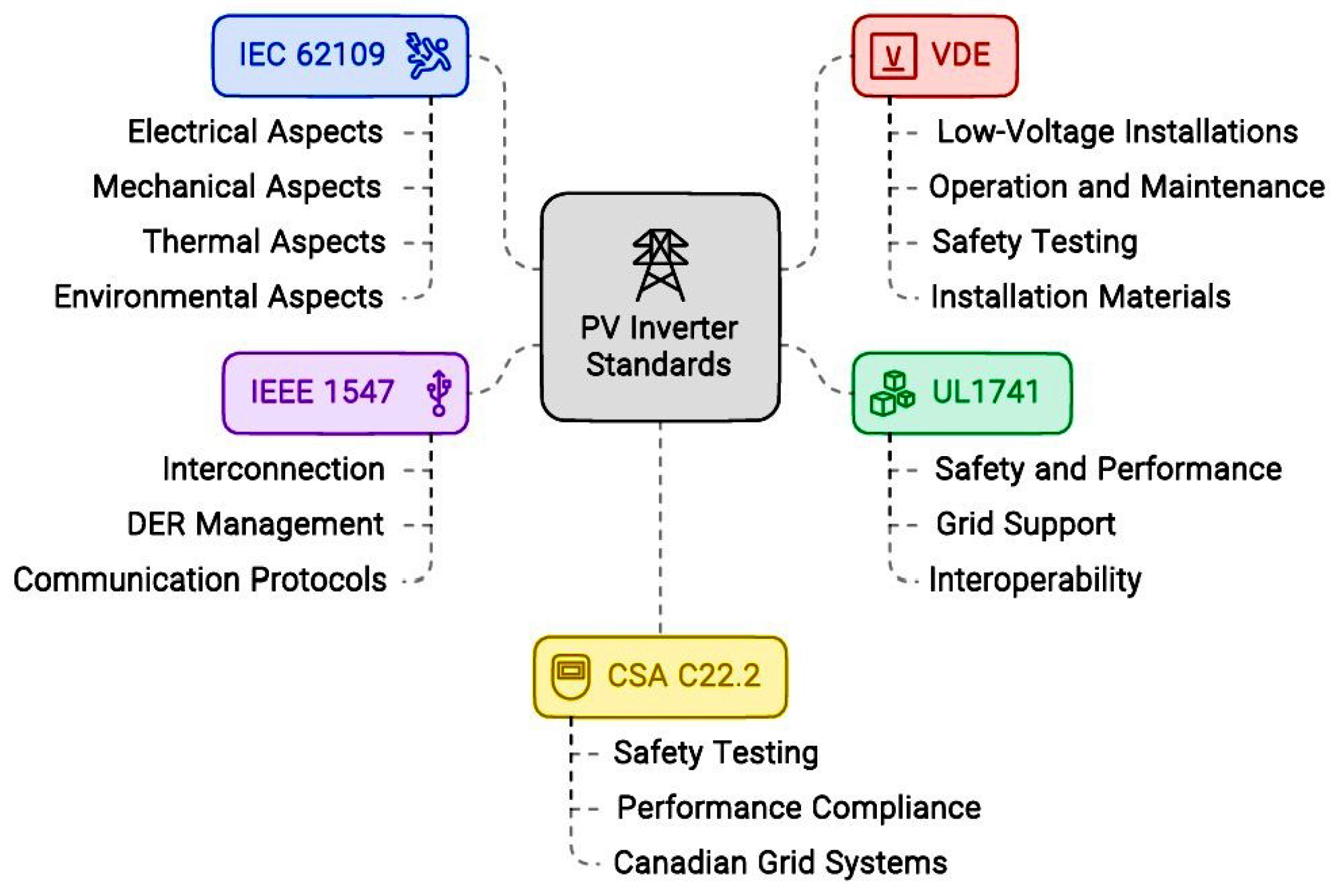
2. Different Standards on PV Inverter Performance
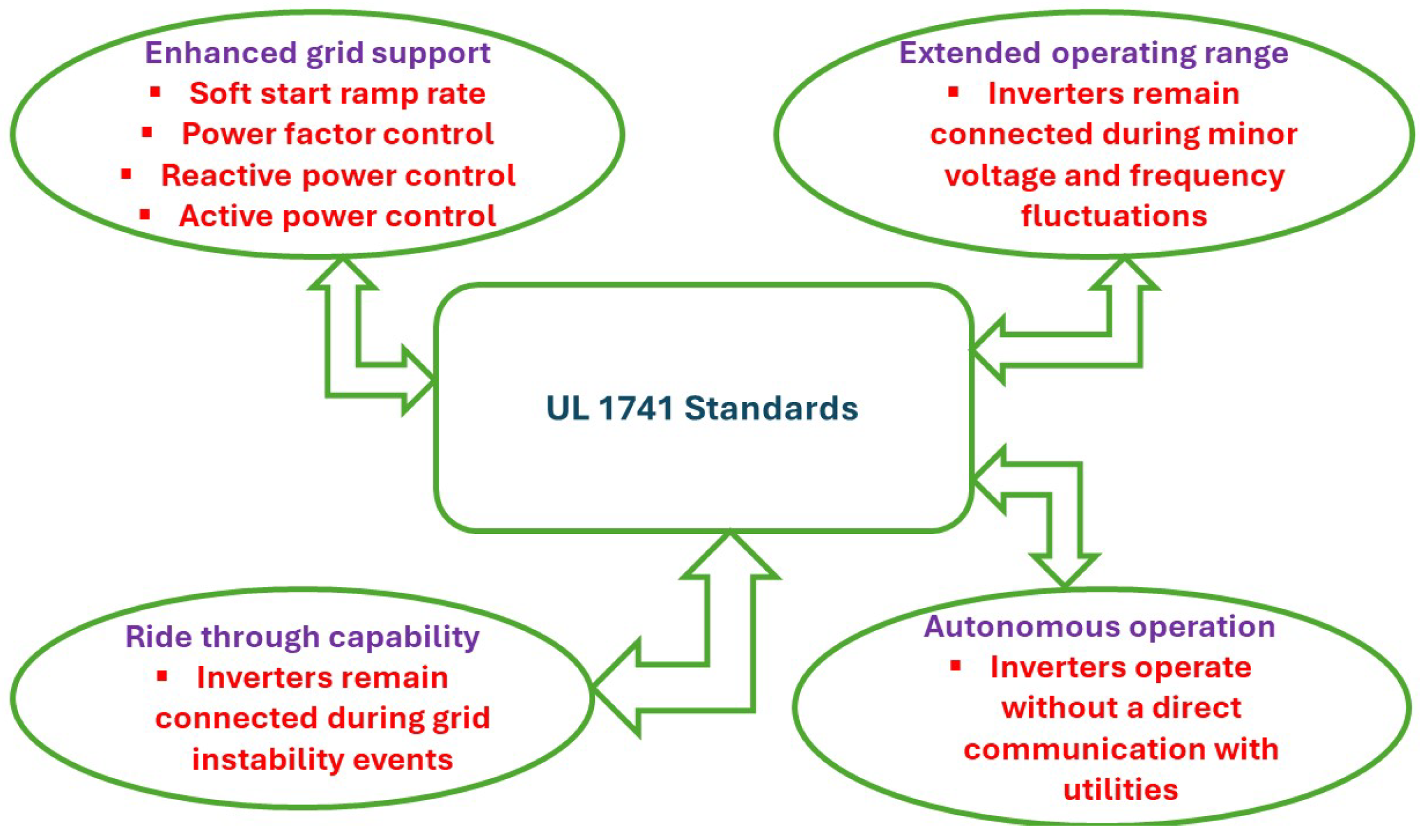
The development of standards is a meticulous and collaborative process involving various stakeholders, including industry experts, manufacturers, regulatory authorities, and standardization bodies. It typically begins with the identification of a need for a new standard or the revision of an existing one. This need can arise from technological advancements, emerging safety concerns, or new regulatory requirements. Once the need is identified, a working group or technical committee is formed, comprising representatives from relevant sectors. These committees are often organized by recognized standardization organizations such as the International Electrotechnical Commission (IEC), the Institute of Electrical and Electronics Engineers (IEEE), or Underwriters Laboratories (UL).
Standards are essential in the field of photovoltaic (PV) inverters for several reasons. Firstly, they ensure safety, protecting both users and equipment from potential hazards such as electrical shocks, fires, and equipment failures [39]. Standards like UL1741 and IEC 62109 set stringent safety requirements that manufacturers must adhere to, thereby minimizing risks and enhancing the overall reliability of PV systems [38,40,41,42]. Secondly, standards facilitate interoperability and compatibility with the electrical grid. For instance, IEEE 1547 outlines the necessary performance and operational criteria for interconnecting distributed energy resources with the grid, ensuring that PV inverters do not disrupt grid stability and can support essential grid functions like voltage regulation and frequency control [43].
Moreover, standards play a crucial role in ensuring quality and reliability. Compliance with standards like CSA C22.2 guarantees that PV inverters meet high-quality benchmarks and are reliable over their expected operational lifespan [44,45]. This is important not only for consumer confidence but also for the economic viability of PV systems, as it reduces maintenance costs and downtime [46,47]. Additionally, standards are key to regulatory compliance and market acceptance. In many regions, adherence to specific standards is a legal requirement for grid connection, and products that meet these standards are more likely to gain approval from utilities and regulatory bodies. This compliance facilitates smoother market entry and acceptance, both domestically and internationally, and enhances the competitiveness of products in the global market. A brief overview of all these standards relevant to PV inverter technology is given in subsequent subsections.

2.1. UL1741

The UL1741 standard, developed by Underwriters Laboratories (UL), is a critical benchmark for the safety and performance of inverters, converters, controllers, and interconnection system equipment for use with distributed energy resources (DERs), including photovoltaic (PV) systems. Established in response to the growing deployment of renewable energy technologies, UL1741 ensures that these systems can be safely and reliably connected to the electrical grid.
The primary purpose of UL1741 is to provide a comprehensive set of safety requirements for the design and construction of grid-tied inverters and related equipment. This standard addresses potential risks associated with electrical, mechanical, and environmental factors, thereby protecting both end-users and the broader electrical infrastructure. The scope of UL1741 covers a wide range of equipment types, including standalone and utility-interactive inverters, power converters, charge controllers, and interconnection system equipment [48]. The specific protocols as set by UL1741 for PV inverters are as follows:
  • Enhanced Grid Support Functions
    • Soft Start Ramp Rates: Inverters are to provide predictable, smooth power production ramp rates when connecting to the grid.
    • Power Factor Application: Inverters are to apply a specified power factor to maintain grid stability.
    • Reactive Power Control: Inverters have to manage grid voltage by providing reactive power.
    • Active Power Control: Inverters are required to regulate grid voltage and frequency by controlling the power output.
  • Extended Operating Range: Inverters must stay connected during minor voltage and frequency fluctuations, supporting the grid rather than disconnecting. This is a significant shift from previous mandates that required inverters to disconnect immediately upon detecting out-of-range voltage or frequency.
  • Ride-Through Capability: Inverters are required to ride through grid instability events, maintaining their connection and supporting grid stability rather than tripping offline. This capability, known as ride-through, ensures that renewables strengthen the grid during instability rather than contributing to the problem.
  • Autonomous Operation: The new standards mandate that inverters operate autonomously without a direct communication link to utility companies. Inverters continuously monitor the grid locally and respond based on real-time conditions.
  • Shutdown Protocol for Safety: In case of a power outage, UL1741-SA requires inverters to shut down to prevent back-feeding electricity into the grid, which could endanger first responders and utility line workers.
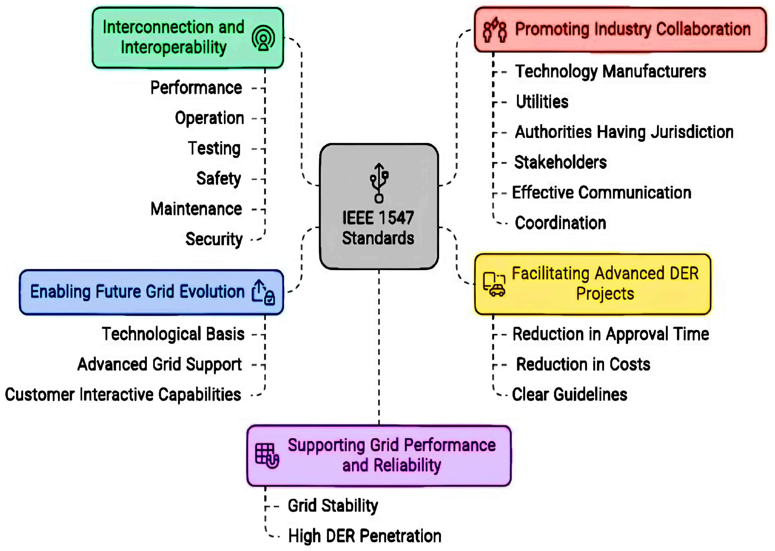
As a conclusion, the UL1741 standard significantly enhances the role of inverters in maintaining grid stability. By allowing inverters to remain connected during minor fluctuations and mandating ride-through capabilities, the standard ensures that distributed renewable energy resources can effectively support the grid. These advancements promote a more resilient and reliable electrical grid, aligning renewable energy technologies with the dynamic needs of modern power systems. Figure 1 presents the salient features of UL1741 standards.

2.2. IEEE 1547

The IEEE 1547 standard is a foundational guideline established by the Institute of Electrical and Electronics Engineers (IEEE) for the interconnection and interoperability of distributed energy resources (DERs) with electric power systems. It provides comprehensive criteria and requirements for the performance, operation, testing, and safety of DERs, which include renewable energy sources like solar photovoltaics (PV), wind turbines, and energy storage systems [49,50,51]. IEEE 1547 plays a crucial role in enhancing grid reliability, promoting the integration of renewable energy, and supporting the transition to a more sustainable and resilient energy infrastructure. The standard addresses key aspects such as voltage regulation, frequency response, anti-islanding protection, and ride-through capabilities, making it an essential reference for utilities, manufacturers, and installers involved in the deployment of distributed energy technologies. The key objectives of the IEEE 1547 Standards for Distributed Energy Resources Interconnection are as follows:
  • Interconnection and Interoperability: The primary goal of these standards is to establish uniform guidelines for the interconnection and interoperability of distributed energy resources (DER) with electric power systems (EPS). This includes defining requirements for performance, operation, testing, safety, maintenance, and security considerations.
  • Supporting Grid Performance and Reliability: The standards aim to ensure that grid performance and reliability levels are maintained or enhanced when integrating DER with the grid. By providing engineering consensus on proper interconnection practices, these standards help maintain grid stability even with high levels of DER penetration.
  • Facilitating Advanced DER Projects: The standards seek to reduce interconnection approval time and costs for advanced DER projects. By streamlining the approval process and providing clear guidelines, these standards support the efficient integration of new technologies into the grid.
  • Enabling Future Grid Evolution: IEEE 1547 Standards is crucial for the evolution of the electricity infrastructure. They provide a technological basis for updating implementation rules and agreements to accommodate advanced grid support features and customer interactive capabilities, ultimately contributing to grid reliability and robustness.
  • Promoting Industry Collaboration: These standards foster collaboration between technology manufacturers, utilities, authorities having jurisdiction (AHJs), and other stakeholders. By establishing a common framework, the standards facilitate effective communication and coordination among the different entities involved in DER integration.
IEEE 1547 Standards ensure the seamless integration of renewable energy sources with the electricity grid by providing uniform requirements, addressing safety and performance standards, supporting grid modernization, reducing approval time and costs, enhancing grid awareness, and enabling high penetration of DER. The specific guidelines as set by IEEE 1547 standards are as follows:
  • Voltage Regulation: The standard defines two performance categories for distributed energy resources (DERs) with voltage regulation capabilities. Category A covers the minimum performance capabilities needed for area electric power system (EPS) voltage regulation, while Category B addresses advanced performance capabilities. Additionally, the standard mandates voltage regulation capability for DERs, but the performance is proposed to be at the utility’s discretion.
  • Power Quality: The standard addresses power quality concerns such as flicker, which is defined as the subjective impression of fluctuating luminance caused by voltage fluctuations. Assessment and measurement methods for flicker are defined in IEEE 1453 and IEC 61000-3-7
  • Ride-Through: The ride-through requirements are designed for distribution support as well as bulk system reliability, based on California Rule 21 and Hawaii Rule 14H. The standard specifies that Category II and III ride-through capabilities are sufficient for bulk system reliability.
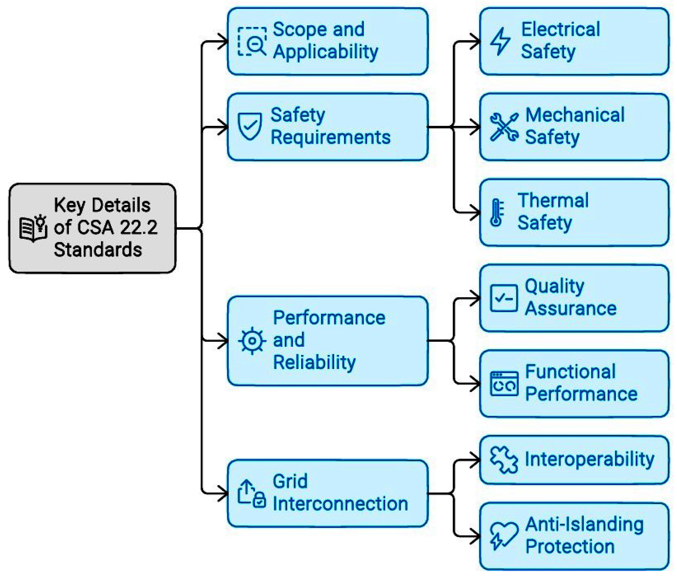
These specific technical guidelines reflect the standard’s focus on ensuring the interconnection and interoperability of distributed energy resources with electric power systems, addressing performance, operation, testing, safety, maintenance, and security considerations. Figure 2 summarizes the features of IEEE 1547.

2.3. CSA 22.2

The CSA 22.2 standards, developed by the Canadian Standards Association (CSA), encompass a series of safety and performance guidelines for electrical and electronic equipment. These standards are crucial for ensuring that products, including photovoltaic (PV) inverters and other distributed energy resources (DERs), meet stringent safety, reliability, and performance criteria [45,52]. The key details of CSA 22.2 standards are as follows:
  • Scope and Applicability: The CSA C22.2 standards apply to a broad spectrum of electrical equipment, including PV inverters, converters, controllers, and other interconnection system equipment used in DERs.
  • Safety Requirements
    • Electrical Safety: Specifications for insulation, grounding, and protection against overcurrent and electric shock hazards.
    • Mechanical Safety: Requirements for mechanical integrity, including construction of enclosures, protection against environmental factors (e.g., dust, moisture), and robustness against physical impacts.
    • Thermal Safety: Guidelines to manage heat dissipation and prevent overheating and fire hazards.
  • Performance and Reliability:
    • Quality Assurance: Standards to ensure the consistent quality and reliability of equipment over its expected operational life.
    • Functional Performance: Criteria for operational performance under various environmental and grid conditions, including voltage and frequency variations.
  • Grid Interconnection:
    • Interoperability: Ensuring compatibility with Canadian grid requirements and other relevant standards, such as IEEE 1547 for DER interconnection.
    • Anti-Islanding Protection: Requirements to prevent inverters from continuing to power isolated sections of the grid, enhancing safety during grid disturbances.
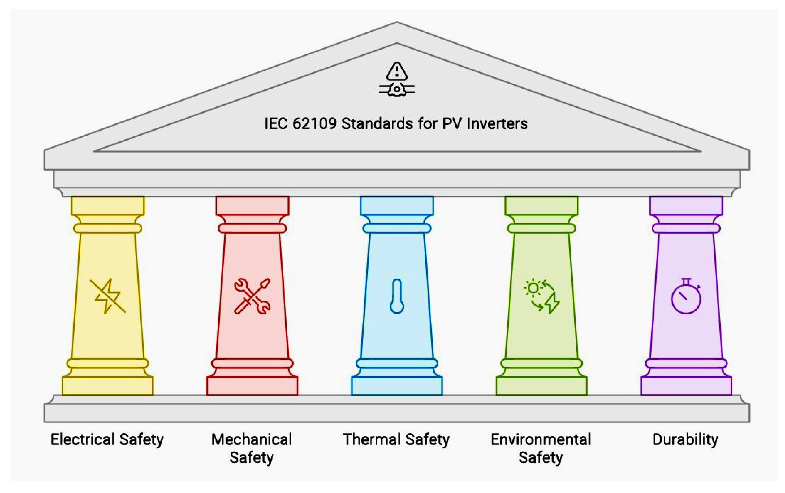
The CSA C22.2 standards are integral to ensuring the safe, reliable, and efficient operation of electrical equipment within Canada. By providing detailed safety, performance, and interoperability guidelines, these standards help protect consumers, enhance product quality, and support the integration of renewable energy systems into the national grid. The key features are summarized in Figure 3.

2.4. IEC 62109

The IEC 62109 standards, established by the International Electrotechnical Commission (IEC), are critical guidelines specifically designed for ensuring the safety of power conversion equipment used in photovoltaic (PV) systems, including PV inverters [38,53,54]. These standards are internationally recognized and provide a comprehensive framework that addresses the unique safety and performance requirements of PV inverters, which are pivotal in converting direct current (DC) generated by solar panels into alternating current (AC) for use in electrical grids and standalone applications.
The primary purpose of IEC 62109 is to safeguard both users and equipment by setting rigorous safety benchmarks that PV inverters must meet. The standards are divided into two main parts: IEC 62109-1 and IEC 62109-2.
  • IEC 62109-1: General requirements for the design and construction of PV inverters to ensure basic safety principles are met. This part covers electrical, mechanical, thermal, and environmental aspects, ensuring that the inverters are robust and safe under various operating conditions.
  • IEC 62109-2: Specific requirements for particular types of inverters, addressing additional risks and safety measures that may apply to specific technologies or configurations. The key safety requirements described by IEC standards are as follows:
  • Electrical Safety:
    • Insulation and Grounding: Specifications for adequate insulation and grounding to prevent electric shock hazards.
    • Protection Against Overcurrent: Requirements for protective devices to prevent damage from overcurrent conditions.
    • Isolation: Standards for electrical isolation to safeguard users and maintain system integrity.
  • Mechanical Safety:
    • Construction: Guidelines for the physical construction of inverters, including the durability of enclosures, protection against the ingress of solid objects and liquids, and resistance to mechanical impacts.
    • Mounting and Accessibility: Standards ensuring that inverters can be safely installed, maintained, and accessed without risk to personnel.
  • Thermal Safety:
    • Overheating Protection: Requirements for managing heat dissipation to prevent overheating, including specifications for thermal management systems and materials.
    • Fire Safety: Guidelines to minimize the risk of fire, including the use of flame-retardant materials and fire containment measures.
  • Environmental Safety:
    • Weather Resistance: Standards for inverters to withstand various environmental conditions, including temperature extremes, humidity, and exposure to UV radiation.
    • Durability: Requirements for long-term durability and reliability under normal operating conditions and environmental stresses.
The IEC 62109 standards are essential for the global PV industry, providing a detailed and robust framework to ensure the safety, reliability, and performance of PV inverters. By adhering to these standards, manufacturers can ensure that their products are safe for consumers and suitable for integration into diverse electrical systems worldwide. Compliance with IEC 62109 not only enhances product safety and reliability but also facilitates international market acceptance, supporting the broader adoption of solar energy technologies. These features are demonstrated in Figure 4.

2.5. VDE

The VDE standards, developed by the Verband der Elektrotechnik Elektronik Informationstechnik (Association for Electrical, Electronic, and Information Technologies), are pivotal in ensuring the safety, quality, and interoperability of photovoltaic (PV) inverters. Recognized internationally, VDE standards address the comprehensive requirements for the design, testing, and certification of PV inverters, ensuring they meet stringent safety and performance criteria. These standards are critical for facilitating the seamless integration of PV inverters into the electrical grid, promoting grid stability, and enhancing the reliability of solar energy systems [55]. By adhering to VDE standards, manufacturers can guarantee that their PV inverters comply with the latest technological and safety advancements, thereby protecting users and contributing to the sustainable growth of the renewable energy sector.
The VDE standards encompass a series of directives covering various sub-areas of electrical systems and equipment. These standards are categorized by the first two digits of their four-digit numerical codes, each addressing specific aspects of electrical safety and performance.
  • VDE 0100 Series:
    • Focus: Installation of low-voltage systems.
    • Content: General protective measures and requirements for electrical installations to ensure functionality and user safety.
  • VDE 0105-100:
    • Focus: Operation of electrical installations.
    • Content: Requirements for the proper operation and maintenance of electrical installations.
  • VDE 0701-0702:
    • Focus: Testing after repair and periodic testing of electrical equipment.
    • Content: Regulations for safety testing of electrical devices post-repair or during regular maintenance.
  • VDE 0500 Series:
    • Focus: Electrical safety of machines and systems.
    • Content: Ensures safety and regulates various converters such as transformers and storage devices (batteries, accumulators).
  • VDE 0600 Series:
    • Focus: Installation material of electronic devices.
    • Content: Nominal specifications for standardized installation materials like switches.
The UL1741, IEEE 1547, CSA C22.2, IEC 62109, and VDE standards collectively provide a comprehensive framework for ensuring the safety, reliability, and interoperability of PV inverters within electrical systems. A comparative depiction of the features of these standards is shown in Figure 5.
Based on the above description, each standard imposes specific requirements and presents unique challenges that must be addressed during the design and development of PV inverters. UL1741 sets out requirements for grid support functions, ensuring that inverters remain connected and operational during grid fluctuations. This standard mandates that inverters autonomously manage grid disturbances without direct communication with utility companies, using local measurements to respond to grid conditions. The challenges associated with UL1741 include ensuring grid stability, developing advanced control algorithms for autonomous operation, and balancing grid support with safety shutdowns during severe disturbances.
IEEE 1547 focuses on the interconnection of distributed energy resources (DER) to the grid, specifying technical requirements for voltage and frequency regulation and appropriate responses to abnormal grid conditions. The challenges here involve harmonizing with the latest revisions of the standard, integrating DERs with existing grid infrastructure, and conducting rigorous testing to validate inverter performance under diverse and potentially harsh grid conditions.
CSA C22.2 ensures that inverters meet stringent safety and performance standards specific to Canada, encompassing electrical compatibility, construction, and design. Challenges include adapting inverter designs to meet regional requirements, achieving high safety standards through thorough testing, and ensuring that materials and components meet specified durability and performance standards.
IEC 62109 emphasizes the safety, reliability, and performance testing of inverters. This globally recognized standard requires inverters to undergo extensive testing to verify their performance and safety, ensuring they can operate reliably over their intended lifespan. The challenges include meeting global standards that address diverse environments and conditions, managing the resource-intensive testing process, and designing inverters that maintain long-term reliability.
VDE standards, specific to the European market, focus on grid interoperability, voltage and frequency regulation, and stringent safety and protection measures. Inverters must seamlessly integrate and communicate with the European grid, providing sophisticated grid support functions while ensuring safety. Challenges include ensuring interoperability with other grid-connected devices, developing advanced grid support features, and meeting VDE’s high safety standards through rigorous testing and robust design.
In summary, understanding the specific requirements and challenges of each standard is essential for developing compliant, reliable, and efficient PV inverters. Each standard addresses different aspects of inverter performance, safety, and interoperability, reflecting the diverse needs of regional and global markets. By meeting these standards, PV inverters can ensure safe and effective integration into the grid, enhancing the reliability and stability of renewable energy systems.

3. Review of Different PV Inverter Topologies

A PV (photovoltaic) inverter, also known as a solar inverter, is an essential component in a solar power system. It converts the direct current (DC) electricity generated by solar panels into alternating current (AC) electricity, which is the standard used by most household appliances and the electrical grid. When selecting a PV inverter, several key features are considered to ensure optimal performance and efficiency [56,57].
  • Grid-connected/Stand-Alone Operation Capability: The ability to operate efficiently in grid-connected or stand-alone modes as required.
  • Isolation: Providing isolation between the input and output to ensure safety and proper functioning of the system.
  • Power Decoupling: The capability to decouple power flow between input and output stages for better control and efficiency.
  • Number of Processing Stages: The number of stages involved in power processing, which can impact system complexity and efficiency.
  • Dual Grounding Capability: Ability to support dual grounding for safety and compliance with standards.
  • Power Handling Capability: The capacity to handle the power requirements of the PV system effectively.
  • Components Count: Keeping the number of components at an optimal level to reduce cost and complexity.
  • Size: Optimal sizing of components and the overall system to meet space and installation requirements.
  • Wide Range of Operation Capability: Ability to operate efficiently over a wide range of operating conditions.
  • Cooling Requirement: Efficient cooling mechanisms to maintain the temperature of components within safe limits.
  • Symmetrical Operation: Operating in a symmetrical manner in both half cycles to minimize DC component injection into the grid/load.
  • Filter Requirement on the AC Side: Incorporating necessary filters on the AC side to meet grid standards and ensure power quality.
  • Complexity Level of Control Strategy: Implementing control strategies that are effective yet manageable for the specific PV application.
In the literature, various types of PV inverter topologies have been developed to meet the specific requirements of different PV systems. Some of the key types of PV inverter topologies are mentioned below.
  • Single-stage inverters: These inverters offer simplicity and efficiency for specific configurations in PV systems [58,59,60].
  • Multi-stage inverters: Including High-Frequency Transformer (HFT), these inverters are suitable for applications requiring high voltage amplification [61,62,63,64,65,66,67].
  • Boost and buck-boost type topologies: These topologies can meet grid conditions in terms of power quality without the need for additional AC side filters [68,69,70,71].
  • Two-stage inverters: Suitable for string configurations or medium power handling capabilities in PV systems [72,73,74,75].
  • Line-frequency inverters: Appropriate for low-power applications such as AC module configurations [76].
  • High-switching frequency voltage source inverters (VSI): Suitable for low- and medium-power PV systems like multi-string and string configurations.
  • Resonant switching topologies: Some single-stage topologies with resonant switching offer better efficiency and a lower number of switches operating at PWM frequencies [77,78].
These topologies are designed to address specific issues and requirements in various types of PV systems, including central, string, multi-string, and AC module configurations. Researchers have proposed and classified these topologies based on factors such as power processing stages, isolation, power rating, output shape, voltage gain, grid interface type, and switching characteristics. A detailed description of each of these topologies is presented in subsequent subsections.

3.1. Single Stage Inverters

A single-stage inverter is a type of power converter that combines the DC-AC conversion process into a single stage, offering simplicity and efficiency for specific configurations in PV systems. The architecture of a single-stage inverter typically consists of a single power conversion stage that directly converts the DC input from the PV source into AC output for grid-connected or stand-alone applications. Components in a single-stage inverter may include power electronic switches (such as MOSFETs or IGBTs), control circuitry, filtering elements, and possibly a transformer for isolation and voltage transformation. The inverter operates by modulating the DC input to create an AC output waveform, usually using pulse-width modulation (PWM) techniques. Single-stage inverters may incorporate features like dual grounding capability, intrinsic boost capabilities, and compact design to meet the specific requirements of PV systems.
The advantages of single-stage inverter topologies include a compact design, lower component count, reduced size and weight, and lower cost. These topologies generally offer good power decoupling and can be more efficient, making them suitable for specific applications. Additionally, single-stage inverters are highly efficient and economical, making them a good choice for certain applications. However, single-stage inverters also have some disadvantages. They typically have restricted power handling capacity, limited output power characteristics, and a narrow range of operation for DC sources. This limitation can result in high peak current stresses on the main power switches, which can restrict their power handling capability. Additionally, single-stage inverters may require a high input capacitor for power decoupling, and they may not be suitable for applications where high power and good performance for a wide range of input voltages are required.

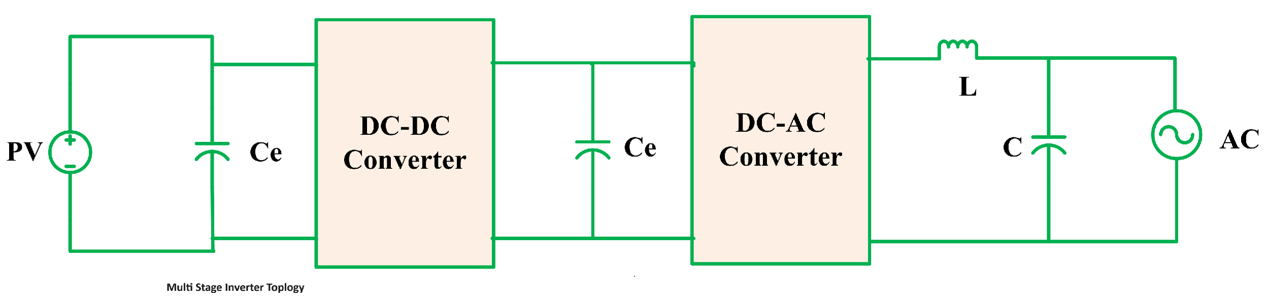
3.2. Multi Stage Inverters

A multi-stage inverter is a type of power converter that involves multiple stages of power conversion to achieve the desired output characteristics. The architecture of a multi-stage inverter typically consists of two or more power conversion stages, each performing specific functions such as voltage transformation, isolation, and output shaping, as shown in Figure 6. Components in a multi-stage inverter may include multiple power electronic switches, transformers, filters, and control circuitry for coordinating the operation of each stage. The stages in a multi-stage inverter may include a DC-DC converter stage for voltage regulation or boosting, followed by a DC-AC inverter stage for generating the AC output waveform. Multi-stage inverters may incorporate features like high-frequency transformers (HFT) for efficient voltage transformation, power decoupling elements for improved control, and advanced control algorithms for optimizing performance.
The advantages of multi-stage inverter topologies include a wider voltage range of operation, good power decoupling, the ability to handle high power, and good performance for a wide range of input voltages. These topologies are suitable for geographic and environmentally varying conditions and can offer high voltage amplification, making them ideal for medium- and high-voltage/power solar PV systems. Additionally, multi-stage inverters can decrease the burden on controller requirements as they allow for MPPT and voltage boosting at the primary stage, while inverting, power control, and grid/load interfacing can be carried out with later-stage converters. However, multi-stage inverters also have some disadvantages. They typically increase the cost, size, and volume of the system due to the additional power processing stages. Additionally, they may require additional components and have a higher level of complexity in control strategies. Furthermore, multi-stage inverters may suffer from higher losses and cooling requirements compared to single-stage inverters, and they may not be as compact in size or have as low a component count.

3.3. Boost and Buck-Boost Type Topologies

Boost and buck-boost type inverter topologies are commonly used in power conversion applications, including solar PV systems. The boost-type inverter is a DC-AC converter that can increase the output voltage level compared to the input voltage level. In a boost inverter, the DC input voltage is boosted to a higher level before being converted into AC output. The boost inverter typically consists of a boost DC-DC converter stage followed by a DC-AC inverter stage. The boost DC-DC converter stage uses an inductor and a switch (such as a MOSFET or IGBT) to store and release energy, boosting the input voltage. The boosted DC voltage is then fed into the DC-AC inverter stage, where it is converted into AC output using pulse-width modulation (PWM) techniques. The architecture of a boost inverter includes components such as the boost converter circuit, inverter circuit, control circuitry, and filtering elements.
The buck-boost type inverter is a versatile DC-DC converter that can either step up or step down the input voltage level. In a buck-boost inverter, the output voltage can be higher or lower than the input voltage, depending on the configuration. The buck-boost inverter topology combines the functions of both buck (step-down) and boost (step-up) converters in a single circuit. The buck-boost inverter typically consists of an inductor, switches, capacitors, and control circuitry to regulate the output voltage. By controlling the switching of the components, the buck-boost inverter can adjust the output voltage level to meet the desired requirements. The architecture of a buck-boost inverter includes components such as the inductor, switches (MOSFETs or IGBTs), capacitors, control circuitry, and filtering elements.
Boost and buck-boost type inverters offer several advantages for power conversion applications. They provide voltage flexibility, allowing adjustment of the output voltage to meet specific needs. These inverters achieve high efficiency in converting DC to AC power and are versatile due to their ability to step up or step down voltage. Additionally, their compact design makes them suitable for space-constrained applications. In conclusion, their voltage flexibility, efficiency, versatility, and compact design make boost and buck-boost inverters crucial in solar PV systems and other power electronics applications.

3.4. Two Stage Inverters

The two-stage inverter topology is a power conversion system that consists of two distinct stages of power conversion to achieve the desired output characteristics. The architecture of a two-stage inverter typically includes two main stages: a DC-DC converter stage and a DC-AC inverter stage. The DC-DC converter stage is responsible for converting the input DC voltage to a different DC voltage level, which is then fed into the DC-AC inverter stage. The DC-AC inverter stage converts the DC voltage from the DC-DC converter into the AC output voltage, typically using pulse-width modulation (PWM) techniques. Components in a two-stage inverter may include power electronic switches (such as MOSFETs or IGBTs), inductors, capacitors, control circuitry, and filtering elements. The two-stage inverter topology allows for independent control and optimization of each stage, enabling efficient power conversion and output regulation.
Two-stage inverters offer several advantages, including higher efficiency by dividing the power conversion process, better voltage regulation and control for stable output, flexibility in adapting to various input voltages and loads, modularity for easier maintenance and scalability, and improved power quality with reduced harmonics. However, they also present some disadvantages, such as increased complexity in design and operation, higher costs due to additional components, larger physical size, and potential efficiency trade-offs due to interactions between stages.

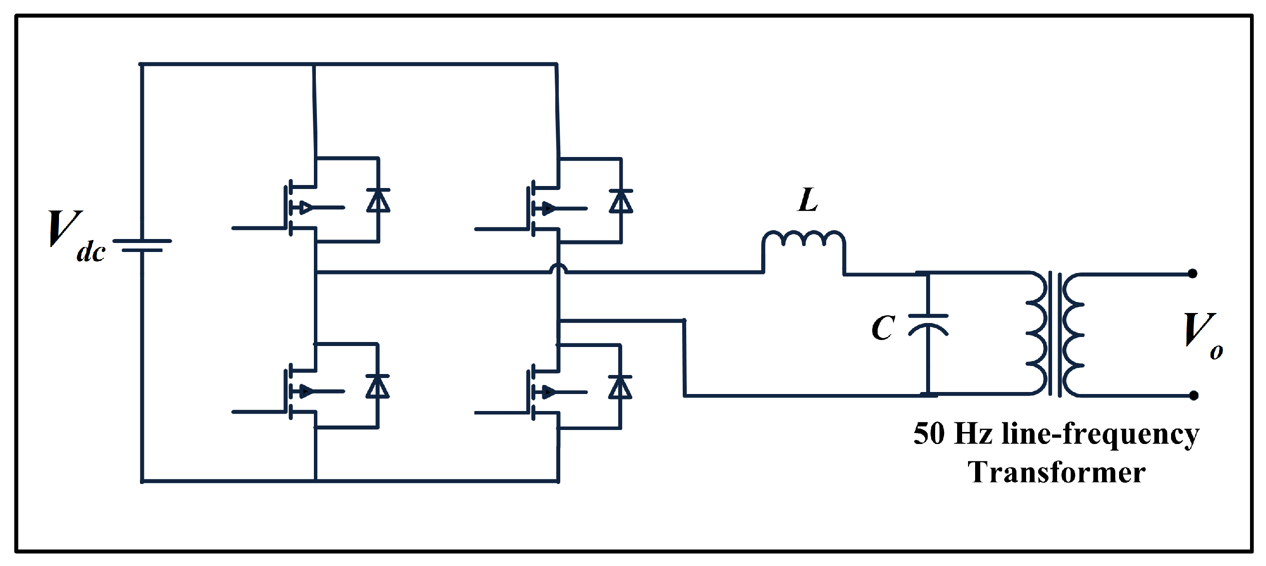
3.5. Line Frequency Inverters

The line frequency inverter topology is a power conversion scheme that utilizes a line frequency inverter on the grid side to convert direct current (DC) from a photovoltaic (PV) panel into alternating current (AC) for grid connection. This topology eliminates the need for a DC link, resulting in improved reliability and higher efficiency due to the reduction in the number of stages between the source and load. However, it suffers from poor power decoupling and power quality for high ratio frequency conversion compared to other topologies.
Advantages of the line frequency inverter topology include the utilization of a line frequency inverter on the grid side, which reduces switching losses. It also offers electrical isolation between the PV panel and the load/grid, resulting in high gain and fault-tolerant capability of the system. However, this topology requires more components to achieve the required voltage gain, which increases the overall price and reduces the system’s efficacy. Disadvantages of the line frequency inverter topology include poor power decoupling and power quality for high ratio frequency conversion compared to other topologies. Additionally, it suffers from limitations in achieving the required voltage gain, which can impact the overall efficiency and cost-effectiveness of the system. In summary, the line frequency inverter topology offers advantages such as reduced switching losses and electrical isolation between the PV panel and the load/grid, but it also has limitations in terms of power decoupling and power quality for high ratio frequency conversion. A circuit diagram of the line frequency inverter is provided in Figure 7.

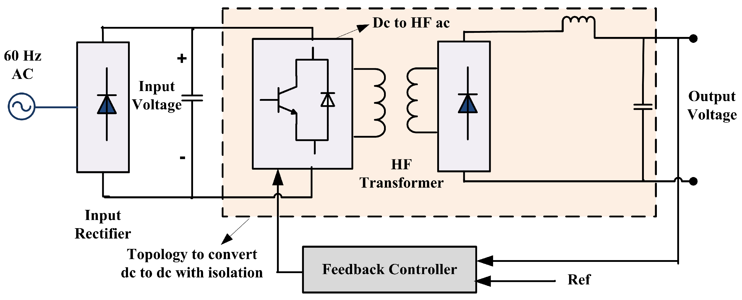
3.6. High Switching Frequency Inverters

The high switching frequency inverter topology is a power conversion scheme that operates at a high frequency to convert direct current (DC) from a photovoltaic (PV) panel into alternating current (AC) for grid connection. This topology offers advantages such as compactness, reduced high-frequency transformer size, and increased efficiency due to the high-frequency switching. However, it also presents challenges such as increased losses due to high-frequency operation and the need for complex control schemes.
The architecture of the high switching frequency inverter topology as presented in Figure 8, involves the use of high-frequency switching to enable the conversion of DC to AC. This allows for a reduction in the size of the high-frequency transformer, making the inverter design more compact. Additionally, the high-frequency operation enables the inverter to achieve high efficiency, as it reduces the size, weight, and cost of passive elements such as inductors, capacitors, and power electronic switches.
Advantages of the high switching frequency inverter topology include compactness, reduced high-frequency transformer size, and increased efficiency due to high-frequency switching. These features make the inverter design more economical and suitable for applications with space constraints. However, the high-frequency operation can also lead to increased losses, requiring careful thermal management and cooling strategies. Additionally, the complex control schemes required for high-frequency operation can add to the overall system complexity.
In summary, the high switching frequency inverter topology offers advantages such as compactness, reduced high-frequency transformer size, and increased efficiency. However, it also presents challenges such as increased losses due to high-frequency operation and the need for complex control schemes.

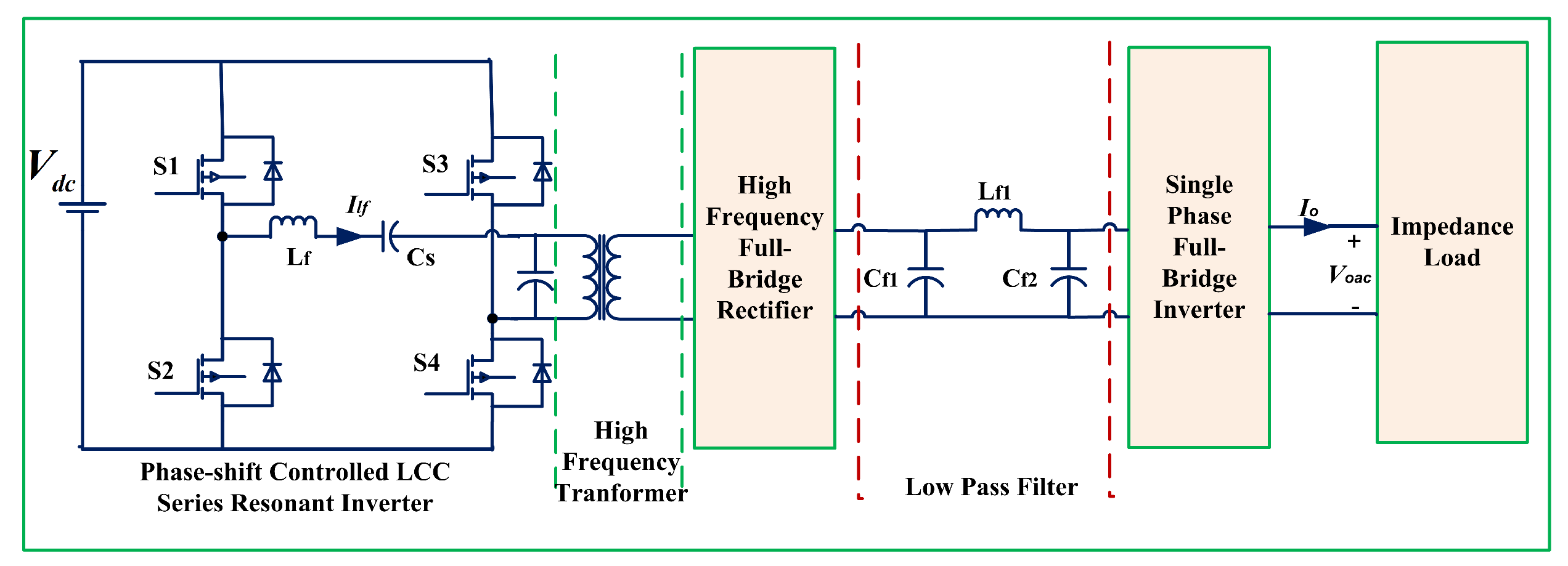
3.7. Resonant Switching Inverters

Resonant switching inverters utilize resonant circuits to achieve soft switching of power electronic devices, reducing switching losses and improving efficiency. The architecture of a resonant switching inverter typically includes resonant circuits (such as LC or LCL) in addition to the traditional power conversion stages. The resonant circuit is designed to create a resonance effect that allows the power electronic switches to turn on or off at zero voltage or zero current points, reducing switching losses. The resonant circuit is typically connected in parallel with the power electronic switches, forming a resonant tank that stores and releases energy during the switching transitions. A circuit view of a resonant frequency PV inverter is given in Figure 9.
Components in a resonant switching inverter may include power electronic switches (such as MOSFETs or IGBTs), resonant inductors and capacitors, control circuitry, and filtering elements.
Advantages of the resonant switching frequency inverter topology include reduced switching losses, improved efficiency, and the ability to control the output side impedance for optimal matching of source and load characteristics. Additionally, the LLC resonant converter offers smaller circulating energy than other resonant converters, leading to significantly increased efficiency in the PV system.
Disadvantages of this topology include the need for high-frequency operation to achieve the required voltage gain, which can lead to increased circulating energy and lower efficiency. Additionally, some resonant converters, such as the series resonant converter, may suffer from output voltage regulation issues under light load conditions.
In summary, the resonant switching frequency inverter topology offers advantages such as reduced switching losses, improved efficiency, and the ability to control output side impedance. However, it also presents challenges such as the need for high-frequency operation and potential issues with voltage regulation under light load conditions.

3.8. Emerging Trends in PV Inverter Topology and Control Strategies

In recent years, the field of PV inverter topologies has seen significant innovation and the emergence of novel configurations aimed at improving efficiency, reliability, and grid compatibility. One notable trend is the development of multilevel inverters, such as neutral-point clamped (NPC) and flying capacitor (FC) inverters, which offer superior performance in high-power applications by reducing the voltage stress on power devices and improving the quality of the output waveform. These multilevel inverters are particularly advantageous in large-scale solar farms and industrial applications where high efficiency and low harmonic distortion are critical.
Another emerging trend is the integration of wide bandgap (WBG) semiconductor devices, such as silicon carbide (SiC) and gallium nitride (GaN), into inverter designs. These materials offer significant advantages over traditional silicon-based devices, including higher switching frequencies, lower losses, and improved thermal performance. The use of SiC and GaN devices enables the development of more compact and efficient inverters, which are crucial for both residential and commercial solar applications. Additionally, the enhanced thermal properties of WBG materials allow for higher power densities, further reducing the size and cost of the inverters.
As inverter topologies evolve, so do the control strategies required to optimize their performance and ensure compliance with stringent grid codes and standards. Advanced control strategies are essential for maximizing the efficiency, reliability, and grid compatibility of modern inverters. One key area of development is model predictive control (MPC), which uses mathematical models to predict the future behavior of the inverter and the grid, allowing for real-time optimization of switching actions. MPC is particularly effective in multilevel inverters, where the increased number of switching states can be leveraged to achieve superior performance in terms of harmonic reduction and dynamic response. Another important control strategy is the use of adaptive and self-learning algorithms. These algorithms can adjust the inverter’s operating parameters in real-time based on changing grid conditions and load demands. For example, adaptive control techniques can optimize the power factor and harmonic compensation dynamically, ensuring that the inverter operates at peak efficiency regardless of external conditions. Self-learning algorithms, often based on machine learning techniques, can further enhance the inverter’s performance by continuously improving the control strategy based on historical data and real-time feedback. Furthermore, blockchain and IoT technologies are opening new avenues for inverter control and management. Blockchain can enable secure and transparent peer-to-peer energy trading, while IoT devices can provide real-time monitoring and control of inverters, enhancing their reliability and efficiency. These technologies can also facilitate predictive maintenance, reducing downtime and extending the lifespan of the inverters.
In conclusion, the continuous evolution of inverter topologies and control strategies is driving significant improvements in the efficiency, reliability, and grid compatibility of PV inverters. The integration of advanced materials, hybrid configurations, and smart functionalities, combined with sophisticated control algorithms, is paving the way for more resilient and adaptable solar power systems. As these technologies mature, they will be crucial in the transition towards a more sustainable and decentralized energy future.

4. Investigation of Different PV Inverter Topologies for Standards Compliance

When considering the investigation of different PV inverter topologies for compliance with various standards, it is essential to delve deeper into the specific requirements of each standard. For instance, some standards may focus on grid-tied systems and require strict adherence to voltage and frequency regulations, while others may emphasize safety features such as ground fault protection and isolation requirements. When considering the investigation of different PV inverter topologies for compliance with various standards, it is essential to delve deeper into the specific requirements of each standard. For instance, some standards may focus on grid-tied systems and require strict adherence to voltage and frequency regulations, while others may emphasize safety features such as ground fault protection and isolation requirements. As we explore various PV inverter topologies, it is important to consider how each design aligns with the specific standards in terms of efficiency, reliability, and overall performance. Additionally, the impact of these topologies on power quality, response to grid disturbances, and ability to meet transient requirements should be thoroughly analyzed to ensure compliance with the relevant standards.
This section presents a detailed comparison of the performance of each of the PV inverter topology, with respect to the different requirements of the individual standards. Figure 10 presents the compliance status of individual PV inverter topology, with respect to each of the standards.

4.1. Quantified Compliance Methodology

In order to systematically evaluate and compare the compliance of different PV inverter topologies with various standards (UL1741, IEEE 1547, CSA C22.2, IEC 62109, and VDE), we introduce a quantified compliance methodology. This approach assigns weightage to each compliance requirement and calculates the performance of each topology based on these weights. Each compliance requirement is evaluated on a scale, and the scores are summed to provide an overall compliance score for each topology. This quantified approach allows for a more objective and comprehensive comparison, highlighting the strengths and weaknesses of each topology in meeting the specified standards.
This approach involves several key steps. First, weightages are assigned to each compliance requirement based on their importance on a scale from 1 to 5. For example, grid support functions for UL1741 are given a weightage of 5, interconnection requirements for IEEE 1547 a weightage of 4, safety and performance for CSA C22.2 a weightage of 3, safety and reliability for IEC 62109 a weightage of 4, and interoperability for VDE a weightage of 3. The justification for these weight assignments is as follows.
A hierarchical preference of operational states has been considered for the PV inverters in this work. PV inverters are mostly employed in a grid-tied-mode microgrid system, where they are supposed to operate in synchronism with the conventional grid. Therefore, grid support function features have been given a maximum weightage of 5. Subsequently, the capability to interconnect with a conventional grid has been given a weight value of 4. IEC 62109 provides safety and security features of PV inverter in interconnected mode. So it has been given a 4 weight. Following the hierarchy, the isolated mode safety, reliability, and interoperability have been assigned the least weightage of 3.
Next, each PV inverter topology is evaluated against these compliance requirements on a scale of 0 to 10. These scores reflect how well each topology meets the specific requirements of each standard. Then, to calculate the overall compliance score for each topology, the evaluation score for each requirement is multiplied by the respective weightage to obtain a weighted score. The weighted scores for each requirement are summed to provide a total compliance score for each topology. This methodology allows for a detailed and objective comparison of the various topologies, highlighting their strengths and weaknesses in meeting the standards. By quantifying compliance, we can present a clear and comprehensive assessment that aids in understanding which topologies are best suited for different regulatory environments.
A quantified assessment of the PV inverter topology adherence to different standards has been carried out, and the results are tabulated in Table 1 and Table 2. Table 1 presents the weight assignment to each required or desired parameter as per different standards, and Table 2 presents the evaluation of each of the topologies for the fulfillment of these parameters.

4.2. Case Study and Numerical Analysis

The rapid adoption of photovoltaic (PV) systems has necessitated advancements in inverter technology to ensure efficient solar energy conversion, maintain power quality, and comply with stringent grid codes. This case study explores the technical capabilities of various PV inverter topologies, including single-stage inverters, multi-stage inverters, boost and buck-boost type topologies, two-stage inverters, line-frequency inverters, and resonant switching topologies. These topologies are compared based on total harmonic distortion (THD), power quality, fault tolerance, and low voltage ride-through (LVRT) capabilities.
A comparison of different multilevel inverter topologies such as diode-clamed multilevel inverters (DCMLI), flying capacitor multilevel inverters (FCMLI), and cascade H-bridge multilevel inverters (CHBMLI) for their THD performances has been performed [79]. A comparison of 3-, 5-, and 7-level inverters reveals that the CHBMLI has less THD, making it a preferable topology for PV applications. Compared to conventional topologies, hybrid multilevel and five-level inverters have better fault-tolerant capabilities when applied for PV applications [80,81]. As far as low voltage ride-through (LVRT) capability is concerned, boost inverters have shown better capability than other topologies [82].

5. Discussion

The results in Table 2 reflect a quantified analysis of the compliance of different PV inverter topologies with respect to major standards, namely UL1741, IEEE 1547, CSA C22.2, IEC 62109, and VDE. Each topology is evaluated based on the key compliance requirements of each standard, and the total scores represent the overall compliance capability of each topology.
Single-stage inverters scored a total of 101 points. They received moderate scores across most standards, reflecting their basic capability to comply with fundamental requirements. However, they struggle with dynamic grid support functions and advanced interconnection requirements. Their design is generally sufficient for basic safety and performance needs but may lack the advanced features required for higher compliance levels, especially in terms of interoperability and grid support. Multi-stage inverters achieved a high total score of 160 points. These inverters are better equipped for grid support functions and advanced requirements, scoring well across all standards. They demonstrate a strong capability to meet safety, performance, and interoperability requirements, making them highly compliant with the comprehensive standards set by UL1741, IEEE 1547, CSA C22.2, IEC 62109, and VDE. Their advanced design and functionality make them suitable for a wide range of applications.
Boost and buck-boost inverters scored 141 points, indicating good potential for compliance. They are flexible and capable of adapting to dynamic grid support and stringent interconnection requirements. They generally perform well in safety and reliability aspects, although they may require moderate adjustments to fully meet all standards. Their robust design ensures they can comply with most requirements, making them a versatile choice. Two-stage inverters obtained the highest total score of 175 points. They excel in all evaluated categories, demonstrating excellent potential for compliance. These inverters are well-suited to meet the stringent requirements of grid support, interconnection, safety, reliability, and interoperability. Their design easily meets the criteria of all major standards, making them the most compliant and versatile among the topologies evaluated.
Line-frequency inverters scored 102 points, reflecting a basic compliance capability. They can meet fundamental safety and performance requirements but may struggle with dynamic grid support functions and advanced interconnection requirements. Their design is generally sufficient for basic needs but may require additional components or modifications to meet higher compliance levels, particularly in terms of advanced features and interoperability. Resonant switching inverters scored 152 points, indicating a high potential for compliance. They are highly efficient and capable of meeting stringent requirements across all standards. They perform well in safety, reliability, and interoperability aspects, making them a strong contender for applications requiring high compliance levels. Their advanced design and high efficiency aid in meeting comprehensive standards effectively.

6. Conclusions

In this paper, a systematic analysis has been conducted to evaluate the compliance of various PV inverter topologies against key standards, including UL1741, IEEE 1547, CSA C22.2, IEC 62109, and VDE. A quantified compliance methodology has been employed, whereby weightages were assigned to critical compliance requirements and each topology’s performance was evaluated against these requirements, resulting in a comprehensive compliance score. The compliance analysis demonstrates that two-stage inverters are the top performers, particularly excelling in environments that demand stringent adherence to grid support, interconnection, safety, and reliability standards. These inverters are ideal for applications requiring high levels of compliance due to their robust design and advanced features. Multi-stage inverters also show strong compliance, making them highly suitable for a variety of applications where advanced safety and grid support functions are critical. Resonant switching inverters and boost/buck-boost inverters exhibit high potential for compliance due to their flexible design, ability to adapt to dynamic grid conditions, and stringent safety requirements. These inverters are well-suited for installations that need versatile and robust solutions. Single-stage inverters and line-frequency inverters, while meeting basic compliance standards, need significant design adjustments to achieve higher compliance levels. These adjustments are particularly necessary for enhancing dynamic grid support functions and meeting advanced interconnection requirements.
Further research is necessary to improve the dynamic grid support capabilities, interoperability, and long-term reliability of PV inverter topologies. Advances in these areas will help ensure that all inverter designs can meet the comprehensive requirements of evolving industrial standards. Enhanced focus on developing more sophisticated control algorithms, better communication protocols, and robust safety features will contribute to achieving higher compliance and better performance in diverse regulatory environments.

Author Contributions

Conceptualization, methodology, validation: M.A.H. and N.K.V.; formal analysis: M.A.H., N.K.V., R.D. and Ł.K.; data curation: M.A.H., N.K.V., R.D. and Ł.K.; writing—original draft preparation: M.A.H., N.K.V., R.D. and Ł.K.; review and editing: Ł.K. All authors have read and agreed to the published version of the manuscript.

Funding

This research received no external funding.

Data Availability Statement

The original contributions presented in the study are included in the article, further inquiries can be directed to the corresponding authors.

Conflicts of Interest

The authors declare no conflicts of interest.

References

  1. Varughese, R.A.; Karpagam, D.R. Prediction of Solar Power Generation Based on Machine Learning Algorithm. In Proceedings of the 2022 Third International Conference on Intelligent Computing Instrumentation and Control Technologies (ICICICT), Kannur, India, 11–12 August 2022; pp. 396–400. [Google Scholar] [CrossRef]
  2. Pourasl, H.H.; Barenji, R.V.; Khojastehnezhad, V.M. Solar energy status in the world: A comprehensive review. Energy Rep. 2023, 10, 3474–3493. [Google Scholar] [CrossRef]
  3. Elavarasan, R.M.; Shafiullah, G.; Padmanaban, S.; Kumar, N.M.; Annam, A.; Vetrichelvan, A.M.; Mihet-Popa, L.; Holm-Nielsen, J.B. A Comprehensive Review on Renewable Energy Development, Challenges, and Policies of Leading Indian States with an International Perspective. IEEE Access 2020, 8, 74432–74457. [Google Scholar] [CrossRef]
  4. S. Pilehvar, M.; Mirafzal, B. Frequency and Voltage Supports by Battery-Fed Smart Inverters in Mixed-Inertia Microgrids. Electronics 2020, 9, 1755. [Google Scholar] [CrossRef]
  5. Nassif, A.B.; Dong, M. Characterizing the Effect of Conservation Voltage Reduction on the Hosting Capacity of Inverter-Based Distributed Energy Resources. Electronics 2020, 9, 1517. [Google Scholar] [CrossRef]
  6. Arbab-Zavar, B.; Palacios-Garcia, E.J.; Vasquez, J.C.; Guerrero, J.M. Smart Inverters for Microgrid Applications: A Review. Energies 2019, 12, 840. [Google Scholar] [CrossRef]
  7. Fujimoto, Y.; Kaneko, A.; Iino, Y.; Ishii, H.; Hayashi, Y. Challenges in Smartizing Operational Management of Functionally-Smart Inverters for Distributed Energy Resources: A Review on Machine Learning Aspects. Energies 2023, 16, 1330. [Google Scholar] [CrossRef]
  8. Xue, Y.; Guerrero, J.M. Smart Inverters for Utility and Industry Applications. In Proceedings of the PCIM Europe 2015; International Exhibition and Conference for Power Electronics, Intelligent Motion, Renewable Energy and Energy Management, Nuremberg, Germany, 19–20 May 2015; pp. 1–8. [Google Scholar]
  9. Mirafzal, B.; Adib, A. On Grid-Interactive Smart Inverters: Features and Advancements. IEEE Access 2020, 8, 160526–160536. [Google Scholar] [CrossRef]
  10. Li, Y.; Yan, J. Cybersecurity of Smart Inverters in the Smart Grid: A Survey. IEEE Trans. Power Electron. 2023, 38, 2364–2383. [Google Scholar] [CrossRef]
  11. Xue, Y.; Starke, M.; Dong, J.; Olama, M.; Kuruganti, T.; Taft, J.; Shankar, M. On a Future for Smart Inverters with Integrated System Functions. In Proceedings of the 2018 9th IEEE International Symposium on Power Electronics for Distributed Generation Systems (PEDG), Charlotte, NC, USA, 25–28 June 2018; pp. 1–8. [Google Scholar] [CrossRef]
  12. Maharjan, M.; Tamrakar, U.; Ni, Z.; Bhattarai, B.; Tonkoski, R. Overvoltage Prevention and Curtailment Reduction Using Adaptive Droop-Based Supplementary Control in Smart Inverters. Appl. Sci. 2021, 11, 7900. [Google Scholar] [CrossRef]
  13. Spring, A.; Wirth, G.; Becker, G.; Pardatscher, R.; Witzmann, R. Grid Influences from Reactive Power Flow of Photovoltaic Inverters with a Power Factor Specification of One. IEEE Trans. Smart Grid 2016, 7, 1222–1229. [Google Scholar] [CrossRef]
  14. Keyhani, A.; Chatterjee, A. Automatic Generation Control Structure for Smart Power Grids. IEEE Trans. Smart Grid 2012, 3, 1310–1316. [Google Scholar] [CrossRef]
  15. Sun, L.; You, F. Machine Learning and Data-Driven Techniques for the Control of Smart Power Generation Systems: An Uncertainty Handling Perspective. Engineering 2021, 7, 1239–1247. [Google Scholar] [CrossRef]
  16. Sabhaya, H.V.; Sheth, V.S. Notice of Removal: Comparative analysis of cascade h-bridge multilevel voltage source inverter. In Proceedings of the 2015 International Conference on Electrical, Electronics, Signals, Communication and Optimization (EESCO), Visakhapatnam, India, 24–25 January 2015; pp. 1–6. [Google Scholar] [CrossRef]
  17. Brovanov, S.V.; Egorov, S.D.; Dubkov, I.S. Study on the efficiency at h-bridge cascaded VSI for different PWM methods. In Proceedings of the 2014 15th International Conference of Young Specialists on Micro/Nanotechnologies and Electron Devices (EDM), Novosibirsk, Russia, 30 June—4 July 2014; pp. 440–443. [Google Scholar] [CrossRef]
  18. Tian, F.; Al-Atrash, H.; Kersten, R.; Scholl, C.; Siri, K.; Batarseh, I. A single-staged PV array-based high-frequency link inverter design with grid connection. In Proceedings of the APEC ’06, Twenty-First Annual IEEE Applied Power Electronics Conference and Exposition, Dallas, TX, USA, 19–23 March 2006; p. 4. [Google Scholar] [CrossRef]
  19. Fallah, M.; Kojabadi, H.M.; Naebi, A.; Shenava, S.J.S.; Chang, L. A novel symmetrical cascade h-bridge multi-level inverter topology with reduced switching devices. In Proceedings of the 2016 IEEE 8th International Power Electronics and Motion Control Conference (IPEMC-ECCE Asia), Hefei, China, 22–26 May 2016; pp. 2389–2393. [Google Scholar] [CrossRef]
  20. Amari, Y.; Hasni, M.; Menaa, M. Comparison between existing transformer-less PV inverter topologies. In Proceedings of the 2018 International Conference on Electrical Sciences and Technologies in Maghreb (CISTEM), Algiers, Algeria, 28–31 October 2018; pp. 1–6. [Google Scholar] [CrossRef]
  21. Deshpande, S.; Bhasme, N.R. A review of topologies of inverter for grid connected PV systems. In Proceedings of the 2017 Innovations in Power and Advanced Computing Technologies (i-PACT), Vellore, India, 21–22 April 2017; pp. 1–6. [Google Scholar] [CrossRef]
  22. Yao, Z.; Zhang, Y.; Hu, X. Transformerless Grid-Connected PV Inverter without Common Mode Leakage Current and Shoot-Through Problems. IEEE Trans. Circuits Syst. II Express Briefs 2020, 67, 3257–3261. [Google Scholar] [CrossRef]
  23. Guo, X.; Yang, Y.; Zhu, T. ESI: A Novel Three-Phase Inverter with Leakage Current Attenuation for Transformerless PV Systems. IEEE Trans. Ind. Electron. 2018, 65, 2967–2974. [Google Scholar] [CrossRef]
  24. Kjaer, S.; Pedersen, J.; Blaabjerg, F. A review of single-phase grid-connected inverters for photovoltaic modules. IEEE Trans. Ind. Appl. 2005, 41, 1292–1306. [Google Scholar] [CrossRef]
  25. Dogga, R.; Pathak, M. Recent trends in solar PV inverter topologies. Sol. Energy 2019, 183, 57–73. [Google Scholar] [CrossRef]
  26. Sharma, S.; Gupta, N. An Overview on Topology and Control Techniques for Solar PV System. In Proceedings of the 2022 1st International Conference on Sustainable Technology for Power and Energy Systems (STPES), Srinagar, India, 4–6 July 2022; pp. 1–6. [Google Scholar] [CrossRef]
  27. Bughneda, A.; Salem, M.; Richelli, A.; Ishak, D.; Alatai, S. Review of Multilevel Inverters for PV Energy System Applications. Energies 2021, 14, 1585. [Google Scholar] [CrossRef]
  28. Kjær, S.B.; Pedersen, J.K.; Blaabjerg, F. Power inverter topologies for photovoltaic modules—A review. In Proceedings of the Conference Record of the 2002 IEEE Industry Applications Conference. 37th IAS Annual Meeting (Cat. No.02CH37344), Pittsburgh, PA, USA, 13–18 October 2002; Volume 2, pp. 782–788. [Google Scholar]
  29. Kolantla, D.; Mikkili, S.; Pendem, S.R.; Desai, A.A. Critical review on various inverter topologies for PV system architectures. IET Renew. Power Gener. 2020, 14, 3418–3438. [Google Scholar] [CrossRef]
  30. Nyamathulla, S.; Chittathuru, D. A Review of Multilevel Inverter Topologies for Grid-Connected Sustainable Solar Photovoltaic Systems. Sustainability 2023, 15, 13376. [Google Scholar] [CrossRef]
  31. Mehta, S.; Puri, V. A review of different multi-level inverter topologies for grid integration of solar photovoltaic system. Renew. Energy Focus 2022, 43, 263–276. [Google Scholar] [CrossRef]
  32. Prakash, G.; Dhineshkumar, K.; Muthamizhan, T.; Rathnavel, P. A Review of Multilevel Inverter Topologies for Solarphotovoltaic System. In Proceedings of the 2022 International Conference on Computer, Power and Communications (ICCPC), Chennai, India, 14–16 December 2022; pp. 632–639. [Google Scholar] [CrossRef]
  33. Vairavasundaram, I.; Varadarajan, V.; Pavankumar, P.J.; Kanagavel, R.K.; Ravi, L.; Vairavasundaram, S. A Review on Small Power Rating PV Inverter Topologies and Smart PV Inverters. Electronics 2021, 10, 1296. [Google Scholar] [CrossRef]
  34. Zeb, K.; Uddin, W.; Khan, M.A.; Ali, Z.; Ali, M.U.; Christofides, N.; Kim, H. A comprehensive review on inverter topologies and control strategies for grid connected photovoltaic system. Renew. Sustain. Energy Rev. 2018, 94, 1120–1141. [Google Scholar] [CrossRef]
  35. Kavya Santhoshi, B.; Mohana Sundaram, K.; Padmanaban, S.; Holm-Nielsen, J.B.; K. K., P. Critical Review of PV Grid-Tied Inverters. Energies 2019, 12, 1921. [Google Scholar] [CrossRef]
  36. IEEE Std 1547-2018 (Revision of IEEE Std 1547-2003); IEEE Standard for Interconnection and Interoperability of Distributed Energy Resources with Associated Electric Power Systems Interfaces. IEEE Standards Association: Piscataway, NJ, USA, 2018; pp. 1–138. [CrossRef]
  37. Gonzalez, S.; Johnson, J.; Reno, M.J.; Zgonena, T. Small commercial inverter laboratory evaluations of UL 1741 SA grid-support function response times. In Proceedings of the 2016 IEEE 43rd Photovoltaic Specialists Conference (PVSC), Portland, OR, USA, 5–10 June 2016; pp. 1790–1795. [Google Scholar] [CrossRef]
  38. Pillai, D.S.; Natarajan, R. A Compatibility Analysis on NEC, IEC, and UL Standards for Protection Against Line–Line and Line–Ground Faults in PV Arrays. IEEE J. Photovolt. 2019, 9, 864–871. [Google Scholar] [CrossRef]
  39. Shrestha, A.; Cater-Steel, A.; Toleman, M.; Rout, T. Benefits and relevance of International Standards in a design science research project for process assessments. Comput. Stand. Interfaces 2018, 60, 48–56. [Google Scholar] [CrossRef]
  40. Mahmud, R.; Hoke, A.; Narang, D. Validating the test procedures described in UL 1741 SA and IEEE P1547.1. In Proceedings of the 2018 IEEE 7th World Conference on Photovoltaic Energy Conversion (WCPEC) (A Joint Conference of 45th IEEE PVSC, 28th PVSEC and 34th EU PVSEC), Waikoloa, HI, USA, 10–15 June 2018; pp. 1445–1450. [Google Scholar] [CrossRef]
  41. Certified safe PV power and grid connect. Photovolt. Bull. 2002, 2002, 4. [CrossRef]
  42. Malik, A.; Haque, A.; Kurukuru, V.B.; Khan, M.A.; Blaabjerg, F. Overview of fault detection approaches for grid connected photovoltaic inverters. E-Prime-Adv. Electr. Eng. Electron. Energy 2022, 2, 100035. [Google Scholar] [CrossRef]
  43. IEEE Std 1547a-2020 (Amendment to IEEE Std 1547-2018); IEEE Standard for Interconnection and Interoperability of Distributed Energy Resources with Associated Electric Power Systems Interfaces–Amendment 1: To Provide More Flexibility for Adoption of Abnormal Operating Performance Category III. IEEE Standards Association: Piscataway, NJ, USA, 2020; pp. 1–16. [CrossRef]
  44. Barth, R.; Chakkalakal, F. Introduction to the new Standards—IEEE STD 844.1™-2017 /CSA C22.2 No. 293.1-17 and IEEE STD 844.2™-2017/CSA C293.2-17 for Skin Effect Trace Heating of Pipelines, Vessels, Equipment, and Structures: Copyright Material IEEE, Paper No. PCIC-2018-20. In Proceedings of the 2018 IEEE Petroleum and Chemical Industry Technical Conference (PCIC), Cincinnati, OH, USA, 24–26 September 2018; pp. 171–178. [Google Scholar] [CrossRef]
  45. Barth, R.; Fenster, N.; Chakkalakal, F. Introduction to the New Standards—IEEE STD 844.3™-2019 /CSA C22.2 No. 293.3-19 and IEEE STD 844.4™-2019/CSA C293.4-19 for Impedance Heating of Pipelines and Equipment. In Proceedings of the 2021 IEEE IAS Petroleum and Chemical Industry Technical Conference (PCIC), San Antonio, TX, USA, 13–16 September 2021; pp. 183–190. [Google Scholar] [CrossRef]
  46. Wiguna, R.B.; Grapurwa, G.; Munnahar, A. Technical and Economic Viability of PV Power Plants Construction for Rural Area in Nunukan North Kalimantan. In Proceedings of the 2022 5th International Conference on Power Engineering and Renewable Energy (ICPERE), Bandung, Indonesia, 22–23 November 2022; Volume 1, pp. 1–6. [Google Scholar] [CrossRef]
  47. Wijesinghe, J.K.; Najim, M.Y.M.; Fernando, G.L.; Liyanage, M.H. Economic Viability of Solar PV for Domestic Applications in a Middle-Income Country: A case Study of Sri Lanka. In Proceedings of the 2020 International Conference and Utility Exhibition on Energy, Environment and Climate Change (ICUE), Pattaya, Thailand, 20–22 October 2020; pp. 1–10. [Google Scholar] [CrossRef]
  48. Satapathy, P.; Dhar, S.; Dash, P. An evolutionary online sequential extreme learning machine for maximum power point tracking and control in multi-photovoltaic microgrid system. Renew. Energy Focus 2017, 21, 33–53. [Google Scholar] [CrossRef]
  49. IEEE Std 1547.9-2022; IEEE Guide for Using IEEE Std 1547 for Interconnection of Energy Storage Distributed Energy Resources with Electric Power Systems. IEEE Standards Association: Piscataway, NJ, USA, 2022; pp. 1–87. [CrossRef]
  50. Anderson, B.; Rane, J.; Khan, R. Distributed wind-hybrid microgrids with autonomous controls and forecasting. Appl. Energy 2023, 333, 120557. [Google Scholar] [CrossRef]
  51. Mohd Razif, A.S.; Ab Aziz, N.F.; Ab Kadir, M.Z.A.; Kamil, K. Accelerating energy transition through battery energy storage systems deployment: A review on current status, potential and challenges in Malaysia. Energy Strategy Rev. 2024, 52, 101346. [Google Scholar] [CrossRef]
  52. Nassif, A.B.; Greenwood-Madsen, T.; Azad, S.P.; Teshome, D.F. Feeder Voltage Management through Smart Inverter Advanced Functions and Battery Energy Storage System. In Proceedings of the 2018 IEEE Power and Energy Society General Meeting (PESGM), Portland, OR, USA, 5–10 August 2018; pp. 1–5. [Google Scholar] [CrossRef]
  53. Shah, P.; Singh, B. Leakage Current Suppression in Double Stage SECS Enabling Harmonics Suppression Capabilities. IEEE Trans. Energy Convers. 2021, 36, 186–196. [Google Scholar] [CrossRef]
  54. Sarkar, S.; Bhaskar, M.; Uma Rao, K.; V, P.; Almakhles, D.; Subramaniam, U. Solar PV network installation standards and cost estimation guidelines for smart cities. Alex. Eng. J. 2022, 61, 1277–1287. [Google Scholar] [CrossRef]
  55. Srinivas, V.L.; Singh, B.; Mishra, S. Enhanced Power Quality PV Inverter with Leakage Current Suppression for Three-Phase SECS. IEEE Trans. Ind. Electron. 2022, 69, 5756–5767. [Google Scholar] [CrossRef]
  56. Lakshika, K.; Boralessa, M.S.; Perera, M.K.; Wadduwage, D.P.; Saravanan, V.; Hemapala, K.U. Reconfigurable solar photovoltaic systems: A review. Heliyon 2020, 6, e05530. [Google Scholar] [CrossRef]
  57. Chen, Y.M.; Liu, Y.C.; Hung, S.C.; Cheng, C.S. Multi-Input Inverter for Grid-Connected Hybrid PV/Wind Power System. IEEE Trans. Power Electron. 2007, 22, 1070–1077. [Google Scholar] [CrossRef]
  58. Salem, O.M.; Fetyan, K.M.; Hashim, M.A. Single Stage Solar PV Inverter Equipped to Water Pumping System. In Proceedings of the 2021 22nd International Middle East Power Systems Conference (MEPCON), Assiut, Egypt, 14–16 December 2021; pp. 353–359. [Google Scholar] [CrossRef]
  59. Jain, S.; Agarwal, V. A Single-Stage Grid Connected Inverter Topology for Solar PV Systems with Maximum Power Point Tracking. IEEE Trans. Power Electron. 2007, 22, 1928–1940. [Google Scholar] [CrossRef]
  60. Zakzouk, N.E.; Abdelsalam, A.K.; Helal, A.A.; Williams, B.W. High Performance Single-Phase Single-Stage Grid-Tied PV Current Source Inverter Using Cascaded Harmonic Compensators. Energies 2020, 13, 380. [Google Scholar] [CrossRef]
  61. Mittal, A.; Janardhan, K.; Ojha, A. Multilevel inverter based Grid Connected Solar Photovoltaic System with Power Flow Control. In Proceedings of the 2021 International Conference on Sustainable Energy and Future Electric Transportation (SEFET), Hyderabad, India, 21–23 January 2021; pp. 1–6. [Google Scholar] [CrossRef]
  62. Shehadeh, S.H.; Aly, H.H.; El-Hawary, M.E. Photovoltaic multi-level inverters technology. In Proceedings of the 2015 IEEE 28th Canadian Conference on Electrical and Computer Engineering (CCECE), Halifax, NS, Canada, 3–6 May 2015; pp. 648–655. [Google Scholar] [CrossRef]
  63. Tarassodi, P.; Siadatan, A.; Keshani, M. Single-Phase Multi-Level Inverter Suitable for Symmetrical and Asymmetrical Photovoltaic (PV) Applications. In Proceedings of the 2019 IEEE 28th International Symposium on Industrial Electronics (ISIE), Vancouver, BC, Canada, 12–14 June 2019; pp. 980–984. [Google Scholar] [CrossRef]
  64. Daravath, R.; Sandepudi, S.R. Control of Two Stage Grid Connected Multi-functional Inverter for Solar Photo Voltaic System. In Proceedings of the 2021 6th International Conference for Convergence in Technology (I2CT), Maharashtra, India, 2–4 April 2021; pp. 1–5. [Google Scholar] [CrossRef]
  65. Sayed, M.A.; Elsheikh, M.G.; Ahmed, E.M.; Orabi, M.; Abdelghani, A.B.; Belkhodja, I.S. Low-Cost Single-Phase Multi-Level Inverter for Grid-Tie PV System Applications. In Proceedings of the Intelec 2013—35th International Telecommunications Energy Conference, SMART POWER AND EFFICIENCY, Hamburg, Germany, 13–17 October 2013; pp. 1–6. [Google Scholar]
  66. Kumar Tatikayala, V.; Dixit, S. Multi-stage voltage control in high photovoltaic based distributed generation penetrated distribution system considering smart inverter reactive power capability. Ain Shams Eng. J. 2024, 15, 102265. [Google Scholar] [CrossRef]
  67. K, V.S.P.; Sudha Rani, P.; Tabita, G. A new multi level inverter topology for grid interconnection of PV systems. In Proceedings of the 2014 POWER AND ENERGY SYSTEMS: TOWARDS SUSTAINABLE ENERGY, Bangalore, India, 13–15 March 2014; pp. 1–5. [Google Scholar] [CrossRef]
  68. Ye, Y.; Chen, M.; Wang, X.; Cao, L. Boost-type common-ground PV inverter based on quasi-Z-source and switched-capacitor. Int. J. Electr. Power Energy Syst. 2023, 144, 108522. [Google Scholar] [CrossRef]
  69. Azizi, M.; Husev, O.; Vinnikov, D. Single-Stage Buck–Boost Inverters: A State-of-the-Art Survey. Energies 2022, 15, 1622. [Google Scholar] [CrossRef]
  70. Rana, N.; Dey, J.; Banerjee, S. An Improved Buck-Boost Converter Suitable for PV Application. In Proceedings of the 2020 IEEE Calcutta Conference (CALCON), Kolkata, India, 28–29 February 2020; pp. 273–277. [Google Scholar] [CrossRef]
  71. Varzaneh, M.G.; Rajaei, A.; Forouzesh, M.; Siwakoti, Y.P.; Blaabjerg, F. A Single-Stage Multi-Port Buck-Boost Inverter. IEEE Trans. Power Electron. 2021, 36, 7769–7782. [Google Scholar] [CrossRef]
  72. Rashwan, A.; Mikhaylov, A.; Hemeida, M.; Pinter, G.; Osheba, D.S. Two-stage grid-connected inverter topology with high frequency link transformer for solar PV systems. Energy Rep. 2023, 10, 1864–1874. [Google Scholar] [CrossRef]
  73. Isakov, I.; Todorovic, I. Power production strategies for two-stage PV systems during grid faults. Sol. Energy 2021, 221, 30–45. [Google Scholar] [CrossRef]
  74. Altin, N.; Ozdemir, S.; Komurcugil, H.; Sefa, I.; Biricik, S. Two-stage grid-connected inverter for PV systems. In Proceedings of the 2018 IEEE 12th International Conference on Compatibility, Power Electronics and Power Engineering (CPE-POWERENG 2018), Doha, Qatar, 10–12 April 2018; pp. 1–6. [Google Scholar]
  75. Fatima, M.; Siddiqui, A.S.; Sinha, S. Implementation of Three-Phase two Stage Solar PV Inverter for Grid Connection. In Proceedings of the 2022 8th International Conference on Advanced Computing and Communication Systems (ICACCS), Coimbatore, India, 25–26 March 2022; Volume 1, pp. 1325–1329. [Google Scholar] [CrossRef]
  76. Abbasi, M.; Kanathipan, K.; Masood Cheema, M.A.; Lam, J. A Line-Frequency Transformer-Less High Frequency Medium Voltage PV Grid Connected Inverter with Extended High Voltage Gain Range. In Proceedings of the 2023 IEEE Applied Power Electronics Conference and Exposition (APEC), Orlando, FL, USA, 19–23 March 2023; pp. 127–132. [Google Scholar] [CrossRef]
  77. Amirabadi, M.; Toliyat, H.A. A new class of PV inverters: Series partial resonant converters. In Proceedings of the 2012 IEEE Energy Conversion Congress and Exposition (ECCE), Raleigh, NC, USA, 15–20 September 2012; pp. 3125–3132. [Google Scholar] [CrossRef]
  78. Altin, N.; Ozdemir, S.; Khayamy, M.; Nasiri, A. A Novel Topology for Solar PV Inverter Based on an LLC Resonant Converter with Optimal Frequency and Phase-Shift Control. IEEE Trans. Ind. Appl. 2022, 58, 5042–5054. [Google Scholar] [CrossRef]
  79. Bhanutej, J.N.; Ravikumar, B.; Rajasekaran, S.; Kalahasthi, N.; Mahalakshmi, K.S. THD Analysis of Different Multilevel Inverter Topologies for PV Applications. In Proceedings of the 2023 3rd International Conference on Smart Generation Computing, Communication and Networking (SMART GENCON), Bangalore, India, 29–31 December 2023; pp. 1–8. [Google Scholar] [CrossRef]
  80. Rooholahi, B.; Peyghami, S.; Bahman, A.S. A New Hybrid-Modular Multi-level Inverter with Fault-Tolerant Capability. In Proceedings of the 2023 25th European Conference on Power Electronics and Applications (EPE’23 ECCE Europe), Aalborg, Denmark, 4–8 September 2023; pp. 1–9. [Google Scholar] [CrossRef]
  81. Rao A, M.; Sahoo, M.; Sivakumar, K. A three phase five-level inverter with fault tolerant and energy balancing capability for photovoltaic applications. In Proceedings of the 2016 IEEE International Conference on Power Electronics, Drives and Energy Systems (PEDES), Trivandrum, India, 14–17 December 2016; pp. 1–5. [Google Scholar] [CrossRef]
  82. Tang, C.Y.; Chen, Y.T.; Chen, Y.F.; Chen, Y.M.; Chang, Y.R. Multi-mode interleaved boost converter for photovoltaic power systems with low-voltage ride-through capability. In Proceedings of the 2013 IEEE Energy Conversion Congress and Exposition, Denver, CO, USA, 15–19 September 2013; pp. 1096–1101. [Google Scholar] [CrossRef]
Figure 1. Salient features of standard UL1741.
Energies 17 03879 g001
Figure 2. Salient features of standard IEEE 1547.
Energies 17 03879 g002
Figure 3. Salient features of standard CSA 22.2.
Energies 17 03879 g003
Figure 4. Salient features of standard IEC 62109.
Energies 17 03879 g004
Figure 5. A comparative representation of different standards for PV inverter topologies.
Energies 17 03879 g005
Figure 6. Multi-stage pv inverter topology.
Energies 17 03879 g006
Figure 7. Line frequency pv inverter topology.
Energies 17 03879 g007
Figure 8. High switching frequency pv inverter topology.
Energies 17 03879 g008
Figure 9. Resonant frequency PV inverter topologies.
Energies 17 03879 g009
Figure 10. Compliance status of individual PV inverter topology, with respect to industry standards.
Energies 17 03879 g010
Table 1. Evaluation Scores (on a scale of 0 to 10) for each topology against these requirements.
TopologyGrid
Support
(UL1741)
Inter
Connection
(IEEE 1547)
Safety
(CSA C22.2)
Reliability
(IEC 62109)
Inter
Operability
(VDE)
Single-stage
Inverters
45675
Multi-stage
Inverters
89898
Boost and
Buck-Boost
78787
Two-stage
Inverters
999109
Line-frequency
Inverters
56655
Resonant
Switching
88888
Table 2. Weighted Scores Calculation.
TopologyGrid
Support
(UL1741)
Inter
Connection
(IEEE 1547)
Safety
(CSA C22.2)
Reliability
(IEC 62109)
Inter
Operability
(VDE)
Total
Score
Single-stage
Inverters
2020182815101
Multi-stage
Inverters
4036243624160
Boost and
Buck-Boost
3532213221141
Two-stage
Inverters
4536274027175
Line-frequency
Inverters
2524182015102
Resonant
Switching
4032243224152
Disclaimer/Publisher’s Note: The statements, opinions and data contained in all publications are solely those of the individual author(s) and contributor(s) and not of MDPI and/or the editor(s). MDPI and/or the editor(s) disclaim responsibility for any injury to people or property resulting from any ideas, methods, instructions or products referred to in the content.

