Abstract
Oxy-fuel combustion technology replaces air with a mixture of pure O2 and recycled flue gas for coal combustion, which leads to difficulties in the waste heat recovery of flue gas in the boiler tail of coal-fired power plants. This paper proposes a new integration scheme for waste heat recovery of flue gas in coal-fired power plants with oxy-fuel combustion CO2 capture. By introducing an oxygen preheater, a recycled flue gas preheater, and a low-pressure economizer, the waste heat of flue gas is fully recovered to preheat oxygen, recycled flue gas, and feed water, respectively. The proposed scheme simultaneously ensures the safe operation of the recycled fan and improves the thermal performance of the coal-fired power plants. Compared to the air combustion configuration, the boiler’s efficiency and gross power efficiency in the oxy-fuel combustion configuration are increased by 0.42% and 1.29%, respectively. Due to power consumption for the added equipment, the net power efficiency is reduced by 10.41%. A techno-economic analysis shows that the cost of electricity for oxy-fuel combustion in coal-fired power plants has increased from USD 46.45/MWh to USD 80.18/MWh, and the cost of the CO2 avoided reaches USD 43.24/t CO2.
1. Introduction
The global warming caused by greenhouse gases has become a significant concern of the international community. Carbon dioxide (CO2) is the primary greenhouse gas accounting for the largest share of radiative forcing. Due to their contribution of nearly 40% of total CO2 emissions in China, coal-fired power plants are confronted with great development challenges under the ‘3060’ target [1,2]. While China has gradually reduced its dependence on fossil fuels, it is unlikely that the coal-based energy structure will change radically in the foreseeable future. Thus, substantial CO2 intensity reduction from coal-fired power plants is critical for China to reach carbon neutrality.
Among various CO2 reduction routes, CO2 capture and storage (CCS) shows great potential as it can directly realize significant CO2 reduction from the existing coal-fired power plants. This technology has the potential to reduce 20% of CO2 emissions by 2050 and 55% by the end of this century [3]. CCS can be summarized into three groups: pre-combustion, post-combustion, and oxy-fuel combustion. The oxy-fuel combustion technology, which refers to coal combustion under the O2-rich atmosphere using an air separation unit (ASU) to remove N2, has great application potential due to its easy introduction to the existing coal-fired power plant [4,5,6]. Unlike air combustion, the exhausted flue gas under oxy-fuel combustion is mainly composed of CO2 and H2O, which greatly increases the CO2 partial pressure and facilitates easy capture of CO2 [7,8,9].
To promote the industrial application of oxy-fuel combustion for CO2 capture in coal-fired power plants, various researchers have studied the fuel combustion characteristics under the oxy-fuel atmosphere over the past few years. For instance, Duan et al. [10] successfully conducted more than 100 h of warm flue gas recycling operation in a 50 kW pilot-scale oxy-fuel circulating fluidized bed combustor. The results showed that the transition from air combustion to oxy-fuel combustion was quite safe, and pollutant emission characteristics under the oxy-fuel combustion configuration were different from those under the air-combustion configuration. Li et al. [11] investigated the sulfur-capture behavior of calcium-based sorbents at a 1 MWth pilot-scale oxy-fuel facility. It was found that sulfur-capture efficiency under oxy-fuel combustion was higher than that under air combustion. Meanwhile, the sulfur-capture efficiency increased with the increase in oxygen concentration. Li et al. [12] investigated the combustion behavior of single-char particles in a transparent fluidized bed combustor under different operating configurations. The results indicated that the pore structure of the char generated in the H2O atmosphere was better than that generated in CO2 and N2 atmospheres. Through numerical investigation, Guo et al. [13] conducted high-fidelity simulations for NOx formation under the fuel-staged and oxygen–fuel two-way staged modes in a 35 MW pulverized oxy-fired boiler. Compared to the baseline oxy-fuel case, the average NO concentration was reduced by 5.6% and 17% under the fuel-staged and oxygen–fuel two-way staged modes, respectively.
Apart from the fuel-combustion characteristics under the oxy-fuel atmosphere, performance analysis for coal-fired power plants with oxy-fuel CO2 capture has captured special attention. Despite the technical feasibility, the oxy-fuel combustion CO2 capture technology requires additional equipment, which considerably increases power consumption and investment costs. Recently, several studies have been conducted on thermodynamic and economic assessments of the oxy-fuel combustion technology in coal-fired power plants. For instance, the effects of the location of flue gas recirculation (FGR) on the energy, exergy, environment, and economics (4E) were investigated by Kim et al. [14] in a 500 MW oxy-fuel ultra-supercritical power plant with CO2 capture. The net efficiencies of the wet flue-gas-recycling and dry flue-gas-recycling power plants reached 37% and 36%, respectively. The levelized cost of electricity was approximately USD 60/MWh. Process efficiency improvement in the combustor and boiler area was possible due to the largest exergy loss. Chen et al. [15] integrated an air separation unit (ASU) and a CO2 compression and purification unit (CPU) into a pressurized fluidized bed oxy-fuel combustion power plant. The results showed that the increased pressure could increase the flue gas dew point, leading to an increase in the boiler’s efficiency due to greater phase-change heat of the moisture in the flue gas. Heat integration of the ASU, CPU, and acid condenser with the steam cycle was conducted to maximize the power production to a net power efficiency of 36.83% in a 600 MW unit. Seo et al. [16] compared the techno-economic performance of ultra-supercritical coal-fired power plants under the air- and oxy-fuel combustion configurations. The net present value and internal return rate of oxy-fuel combustion were 2.3 times and 1.15 times greater than those of air combustion. The investment cost was as sensitive as the fuel cost for coal-fired power plants with oxy-fuel combustion. Maddahi et al. [17] conducted a thermo-economic analysis of a 300 MW steam-generation unit with an oxygen-separation unit and a shock wave CO2-compression unit. To reduce the efficiency penalty, the waste heat from CO2-compression intercoolers and air separation unit coolers was used to boost an organic Rankin cycle for power generation. The oxygen production per unit of power consumption was reduced from 227.3 kWh/t O2 to 214.2 kWh/t O2, the efficiency penalty drop was reduced by 1.51%, and the cost of electricity was reduced from EUR 67.03/MWh to EUR 64.94/MWh.
For conventional coal-fired power plants under the air-combustion configuration, an air preheater is usually applied to recover the waste heat of flue gas to preheat the air, which is an effective way to increase the boiler’s efficiency. However, when air is replaced by a mixture of pure O2 and recycled flue gas (RFG) in the oxy-fuel combustion configuration, the waste heat recovery of flue gas faces some difficulties. While the aforementioned literature made great efforts to show the competitiveness of the oxy-fuel combustion technology, effective measures to recover the waste heat of flue gas for the oxy-fuel combustion process in coal-fired power plants have been rarely reported.
This paper proposes a new integration scheme for coal-fired power plants with oxy-fuel combustion CO2 capture. By effective system integration between the boiler system and steam/water cycle, the waste heat of flue gas under the oxy-fuel combustion configuration is fully recovered. The proposed scheme simultaneously ensures the safe operation of the recycled fan and improves the overall performance of coal-fired power plants. Furthermore, the thermodynamic and techno-economic performances of the proposed scheme are quantitatively analyzed to provide a technical reference for coal-fired power plants with oxy-fuel combustion CO2 capture.
2. Reference Coal-Fired Power Plant
A typical coal-fired power plant with a boiler system and the steam/water cycle is analyzed in this paper as a base case.
Figure 1 shows the flow diagram of the boiler system. The boiler system consists mainly of the economizer, water wall, superheater, reheater and air preheater. In the steam/water flow, the feed water from the steam/water cycle is successively heated by the economizer (E-1, E-2), water wall (WW) and superheater (S-1, S-2, S-3) to become the superheated steam. The superheated steam flows into the high-pressure turbine for power output. The exhaust steam from the high-pressure turbine is heated by the reheater (R-1, R-2) to become the reheated steam. The reheated steam flows into the intermediate-pressure turbine for power output. In the air/flue gas flow, the air is preheated by the air preheater and flows into the furnace for coal combustion.
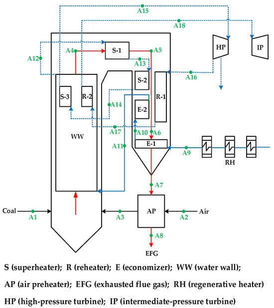
Figure 1.
Flow diagram of boiler system under air combustion configuration. Solid black line: coal and air; solid red line: flue gas; solid blue line: feed water; dotted blue line: steam.
The flue gas produced releases heat for the water wall (WW), superheater (S-3) and reheater (R-2) in the furnace, then releases heat for a superheater (S-1) in the horizontal flue, and, finally, releases heat for a superheater (S-2), reheater (R-1), economizer (E-2) and economizer (E-1) in the boiler tail. The proportion of C, H, O, N, S, moisture and ash in coal by ultimate analysis is 35.60%, 2.24%, 13.29%, 0.77%, 1.14%, 33.40% and 13.59% respectively. Parameters of the boiler system are given in Table 1 and Table 2.

Table 1.
Parameters of boiler system.
Table 2.
Temperature of heat exchangers in boiler system.
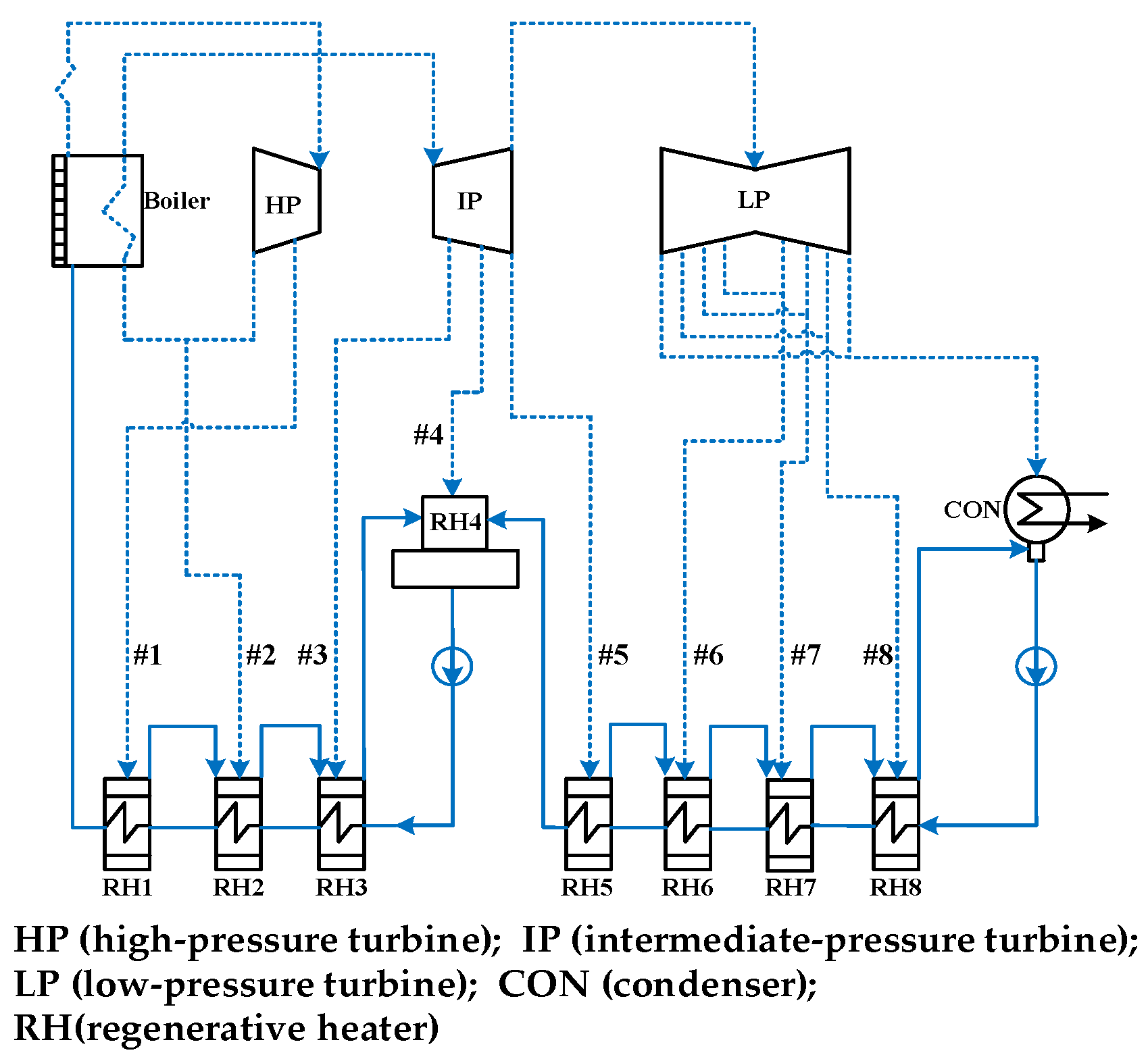
Figure 2 shows the flow diagram of the steam/water cycle. The steam/water cycle consists mainly of the high-pressure turbine, the intermediate-pressure turbine, the low-pressure turbine, the condenser and eight regenerative heaters (RH1–RH8). The superheated steam from the boiler system flows into the high-pressure turbine for power output. The exhaust steam from the high-pressure turbine returns to the boiler system for reheat. The reheated steam flows to the intermediate-pressure turbine and low-pressure turbine for power output. The exhaust steam from the low-pressure turbine flows into the condenser to become the feed water.
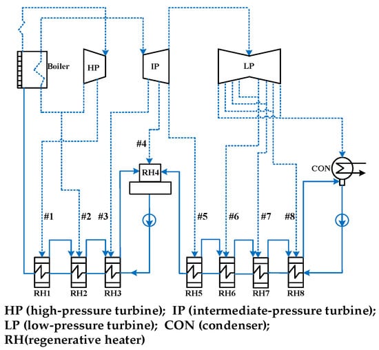
Figure 2.
Flow diagram of steam/water cycle under air combustion configuration. Solid blue line: feed water; dotted blue line: steam.
Before being pumped back into the boiler system, the feed water is preheated by eight regenerative heaters, in which the heat source is steam extraction #1–8 from turbines. The parameters of the steam/water cycle are shown in Table 3.
Table 3.
Parameters of steam-water cycle.
3. Oxy-Fuel Combustion Retrofitting for Coal-Fired Power Plant
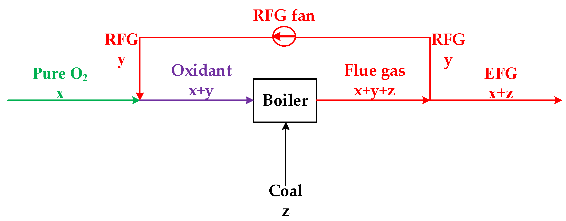
Oxy-fuel combustion in coal-fired power plants replaces air with a mixture of pure O2 and recycled flue gas (RFG). Coal combustion with pure O2 is fast and dangerous, potentially leading to a loss of control of temperature and combustion rate. Mixing with RFG could reduce the inlet O2 concentration and make it easier to control the combustion characteristics. In addition, oxy-fuel combustion with flue gas recycling is beneficial for the reduction of pollutants such as NOx and SO2 [18].
A simplified flow diagram of oxy-fuel combustion with flue gas recycling is shown in Figure 3. Pure O2 (mass flow = x) mixes with RFG (mass flow = y) to form the oxidant mixture (mass flow = x + y) for the boiler. In the boiler, coal (mass flow = z) is burned with oxidant to produce flue gas (mass flow = x + y + z). After leaving the boiler, the flue gas is separated into two streams. One stream is recirculated by a recycled fan to become RFG (mass flow = y) and the other stream is emitted as exhausted flue gas (EFG) (mass flow = x + z).
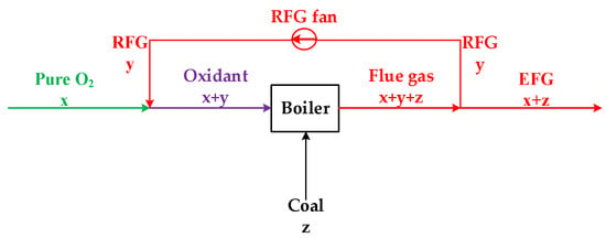
Figure 3.
Simplified flowsheet for oxy-fuel combustion with flue gas recycling.
Under the air combustion configuration, the flue gas from the economizer releases heat to preheat air, which fully recovers the waste heat of the flue gas to improve the boiler’s efficiency. However, it is difficult to recover the waste heat of the flue gas under the oxy-fuel combustion configuration: (1) Due to the presence of N2, the air flow under the air combustion configuration is much larger than the pure O2 flow under the oxy-fuel combustion configuration for the same coal feed rate. As a result, the flue gas still has a high temperature after heat release to preheat the pure O2, which reduces the waste heat recovery ratio. (2) The recycled fan usually operates at a low temperature (below 200 °C). Therefore, the recycled flue gas temperature needs to be reduced to ensure the longevity of the recycled fan, which in turn increases the difficulty of flue gas waste heat recovery.
This paper proposes an effective way to fully recover the waste heat of the exhaust gas under the oxy-fuel combustion configuration, with a detailed flow diagram shown in Figure 4.
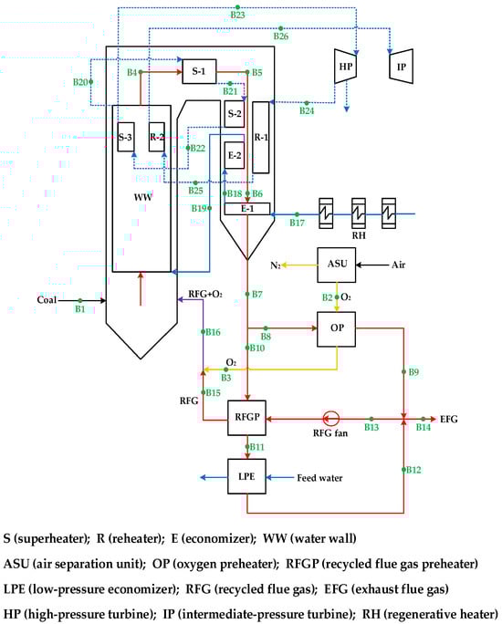
Figure 4.
Flow diagram of boiler system under oxy-fuel combustion configuration. Solid black line: coal and air; solid red line: flue gas; solid blue line: feed water; dotted blue line: steam; solid purple solid line: mixed recycled flue gas (RFG) and pure O2; solid yellow line: separation gas.
For the steam/water flow, the heating process is the same as for the air combustion configuration. For the flue gas flow, the air preheater in the air combustion configuration is shut down and an air separation unit (ASU), an oxygen preheater (OP), a recycled flue gas preheater (RFGP) and a low-pressure economizer (LPE) are added. The pure O2 produced by the ASU mixes with the RFG from the RFGP and flows into the furnace for coal combustion. The flue gas from the economizer (E-1) is separated into two streams. One stream releases heat in the OP to preheat the pure O2. The other stream successively releases heat in the RFGP and LPE to preheat the RFG and feed water, respectively. After mixing the two streams, part of the flue gas is recirculated by the recycled fan while the rest is emitted as EFG for CO2 treatment (CO2 compression and purification). The RFG is preheated in the RFGP and mixed with the pure O2 for coal combustion.
The quantitative results of the tail arrangement under the two combustion configurations are compared in Figure 5.
Figure 5.
Tail arrangement of boiler system under different configurations: (a) air combustion configuration; (b) oxy-fuel combustion configuration. Black line: coal and air; red line: flue gas; blue line: feed water; green line: separation gas O2; yellow line: separated gas N2.
In the air combustion configuration, the flue gas from the economizer (E-1) flows into the AP to preheat the air. In the AP, the flue gas temperature is reduced from 370 °C to 140 °C and the air temperature is increased from 20 °C to 316 °C. In the oxy-fuel combustion configuration, the flue gas from the economizer (E-1) is separated into two streams. One stream (21.2%) flows into the OP to preheat pure O2. In the OP, the flue gas temperature is reduced from 370 °C to 140 °C and the pure O2 temperature is increased from 20 °C to 316 °C. The other stream (78.8%) flows into the RFGP and LPE to preheat the RFG and feed water. In the RFGP, the flue gas temperature is reduced from 370 °C to 241 °C and the RFG temperature is increased from 20 °C to 316 °C. In the LPE, the flue gas temperature is reduced from 241 °C to 140 °C to preheat the feed water of the steam/water cycle. The stream from the OP and the stream from the LPE are mixed at a temperature of 140 °C. A recycled fan recirculates 60% of the flue gas as RFG and the remaining 40% as EFG. The RFG is preheated from 140 °C to 316 °C. Finally, the RFG from the RFGP and the pure O2 from the OP are mixed at a temperature of 316 °C for coal combustion in the boiler, which is the same as the air temperature (316 °C) in the air combustion configuration.
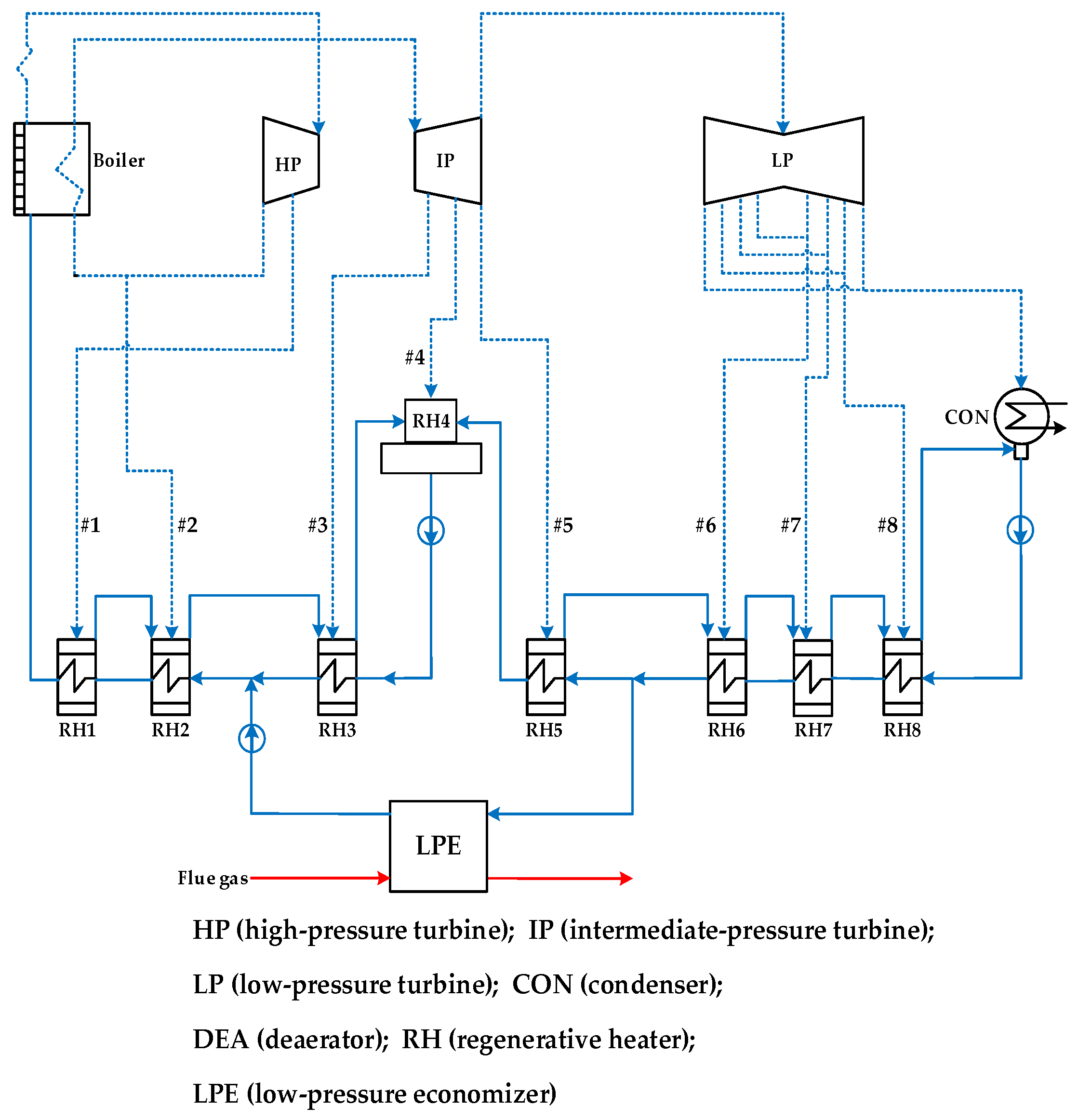
Figure 6 shows the flow diagram of the steam/water cycle in the oxy-fuel combustion configuration. In the original steam/water cycle of coal-fired power plants (Figure 2), the feed water is preheated by eight regenerative heaters, whose heat source is steam extraction #1–#8 from the turbines. In the oxy-fuel boiler system, the added LPE recovers waste heat from the flue gas to preheat the feed water in the steam/water cycle, saving some of the steam extraction. The saved steam extraction could increase the steam flow in the turbines, leading to an increase in gross power output [19]. Considering the flue gas temperature of LPE (241–140 °C), a part of the feed water between RH2 and RH6 (100.3–206.4 °C) flows into the LPE to recover the waste heat of the flue gas.
Figure 6.
Flow diagram of steam/water cycle under oxy-fuel combustion configuration. Solid red line: flue gas; solid blue line: feedwater; dotted blue line: steam.
4. Thermal and Economic Performance
4.1. Research Method
All the work is carried out using Aspen Plus V11 software. The boiler system and steam cycle are simulated separately, with detailed specifications shown in Table 4.
Table 4.
Simulation specifications of coal-fired power plants.
The boiler system is simulated by the ‘PENG-ROB’ property. Coal is defined as a ‘non-conventional’ material where its ultimate analysis, proximate analysis and heat of combustion can be specified. Coal combustion is realized by ‘RYield’ and ‘RGibbs’ blocks. In the ‘RYield’ block, coal is decomposed into its constituent elements. The components are further combusted in the ‘RGibbs’ block, where products with minimum Gibbs free energy are determined. The heat transfer between the flue gas and the steam/water or gas oxidant is realized in the ‘MHeatX’ block, where the temperature of the hot source and the cold source could be calculated based on the thermal equilibrium. Detailed parameters of the boiler system under two different configurations are shown in Table 5 and Table 6.
Table 5.
Detailed parameters of boiler system under air combustion configuration.
Table 6.
Detailed parameters of boiler system under oxy-fuel combustion configuration.
The text continues here (Table 6).
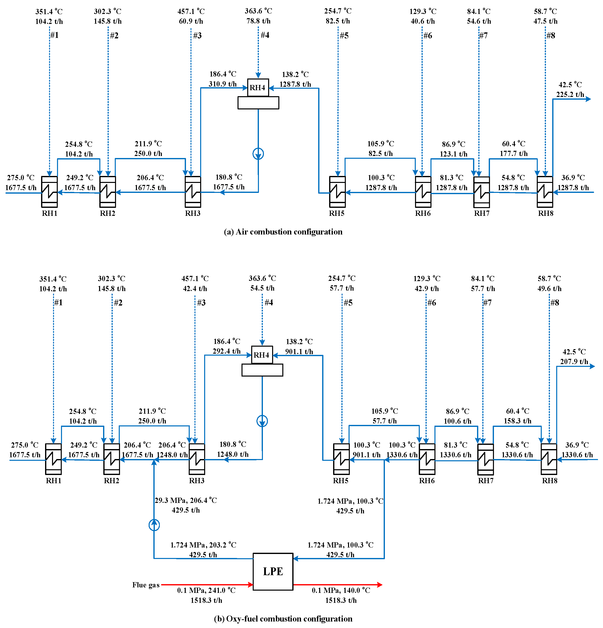
The steam/water cycle is simulated by the ‘STEAM-TA’ property. The ‘Compr’ block and the ‘Pump’ block are used to analyze the pressure change in steam and water, respectively. The ‘MHeatX’ block is used for the heat exchange in the regenerative heaters. The condenser is simulated by the ‘Heater’ block in which the pressure and vapor fraction are specified to determine the heat dissipation to the environment. The ‘Mixer’ and ‘Splitter’ blocks are used to mix and separate the material streams. Detailed parameters of the steam/water cycle under two different configurations are shown in Figure 7.
Figure 7.
Detailed parameters of steam/water cycle under two different configurations. Solid red line: flue gas; solid blue line: feed water; dotted blue line: steam.
It should be noted that the oxy-fuel retrofit idea proposed in this paper is mainly used to fully recover the waste heat of the flue gas in the oxy-fuel combustion configuration. For an existing power plant, when the power plant is converted from the air combustion configuration to the oxy-fuel combustion configuration, the boiler system has to be rebuilt due to the change in boiler size and heat transfer coefficient. For the sake of simplicity, the idea proposed in this paper is designed for a newly built oxy-fuel power plant. The flue gas temperature of the boiler system in the oxy-fuel combustion configuration is designed to be the same as that in the air combustion configuration. The steam/water temperature in each heat transfer area of the boiler system is determined by the thermal balance during heat transfer with the flue gas. The detailed heat transfer coefficient/area between the flue gas and steam/water is not considered.
4.2. Thermal Performance Analysis
To facilitate the comparison of thermal performance, the heat load for superheated and reheated steam is assumed to be the same in different configurations. In fact, the parameters (pressure, temperature and flow) of the superheated and reheated steam remain constant.
4.2.1. Thermodynamic Performance of Boiler System
Table 7 compares the thermodynamic performance of the boiler system under different configurations. The oxidant varies from air to a mixture of pure O2 and RFG. The excess O2 ratio, defined as the ratio of practical O2 flow to theoretical O2 flow, remains constant at 1.225. The RFG ratio is set at 60% in the oxy-fuel combustion configuration.
Table 7.
Comparison of boiler system under different configurations.
The optimization measures proposed in this paper increase the boiler’s efficiency from 92.95% to 93.37% and consequently reduce the coal feed rate from 394.50 t/h to 392.74 t/h. For the oxidant, the inlet O2 concentration is set at 30%, as the oxy-fuel combustion with 30% inlet O2 concentration has similar combustion characteristics to air combustion [20]. Due to the flue gas recycling, the inlet N2 concentration is reduced from 79% to 0.3%, while the inlet CO2 and H2O concentrations are increased to 34.7% and 34.6%, respectively. The same phenomenon could be observed in the EFG where the N2 concentration is reduced from 67.5% to 0.4%, while the inlet CO2 and H2O concentrations are increased from 13.8% and 15.2% to 47.3% and 47.2%, respectively. As a result, the CO2 concentration on a dry basis could reach 89.6% in the oxy-fuel combustion configuration, leading to easy CO2 capture after moisture removal from the EFG.
4.2.2. Thermodynamic Performance of and Overall Performance of Coal-Fired Power Plants with Oxy-Fuel Combustion CO2 Capture
For the parameters of the steam/water cycle under two different configurations in Figure 7, as part of the feed water (429.5 t/h) preheated by the waste heat of the flue gas in the LPE, the feed water in RH3, RH4 and RH5 is reduced from 1677.5 t/h, 1287.8 t/h and 1287.8 t/h (air combustion) to 1248.0 t/h, 901.1 t/h and 901.1 t/h (oxy-fuel combustion), respectively. Consequently, the steam extraction in RH3, RH4 and RH5 is reduced from 60.9 t/h, 78.8 t/h and 82.5 t/h (air combustion) to 42.4 t/h, 54.5 t/h and 57.7 t/h (oxy-fuel combustion), respectively. However, the steam extraction in RH6, RH7 and RH8 is increased in the oxy-fuel combustion configuration compared to the air combustion configuration. For the regenerative heaters, the heat used to preheat the feed water comes from two sources, namely the steam extraction from the turbines and the wastewater from the former heaters. On the one hand, the reduction of steam extraction in RH3 and RH4 increases the feed water in RH6, RH7 and RH8 from 1287.8 t/h (air combustion) to 1330.6 t/h (oxy-fuel combustion); on the other hand, reducing the steam extraction in RH5 reduces the effluent water from 82.5 t/h, 123.1 t/h and 177.7 t/h (air combustion) to 57.7 t/h, 100.6 t/h and 158.3 t/h (oxy-fuel combustion) in RH6, RH7 and RH8, respectively. Consequently, the steam extraction in RH6, RH7 and RH8 increased from 40.6 t/h, 54.6 t/h and 47.5 t/h (air combustion) to 42.9 t/h, 57.7 t/h and 49.6 t/h (oxy-fuel combustion), respectively.
Table 8 compares the thermodynamic performance of the steam/water cycle under different configurations. For the same superheated and reheated steam, the HP turbine power output remains unchanged due to the same steam extraction in RH1 and RH2. While the steam extraction in RH6, RH7 and RH8 is increased, the saved steam extraction in RH3, RH4 and RH5 has a higher energy level, resulting in an increase in the IP and LP turbine power from 157.11 MW and 249.56 MW (air combustion) to 158.07 MW and 263.37 MW (oxy-fuel combustion), respectively.
Table 8.
Thermodynamic performance under different configurations.
Thus, the gross power output is increased from 600.18 MW (air combustion) to 614.95 MW (oxy-fuel combustion). Furthermore, as the coal feed rate is reduced from 394.50 t/h to 392.74 t/h due to the increase in the boiler’s efficiency, the boiler energy input is correspondingly reduced from 1358.36 MW (air combustion) to 1352.30 MW (oxy-fuel combustion). Consequently, the increased gross power output and reduced boiler energy input result in an increase in gross power efficiency from 44.18% to 45.47%.
The thermodynamic performance of the boiler system and the steam/water cycle confirms the advantages of the proposed integration scheme. However, the energy consumption and investment costs of the additional equipment should not be ignored.
The auxiliary equipment mainly includes the air separation unit (ASU), CO2 compression unit (CCU), CO2 purification unit (CPU), oxygen preheater (OP), recycled flue gas preheater (RFGP), low-pressure economizer (LPE) and recycling fan. The power consumption for the ASU is assumed to be a typical value of 0.35 kWh/Nm3 O2 [21,22]. For CCU, a multi-stage compression with intercooling [18] is applied with final CO2 at 11.0 MPa and 20 °C. The power consumptions of the CPU, OP, RFGP, LPE and recycling fan are taken from the existing literature [23,24].
As shown in Table 8, the power consumption for ASU and CCU reaches 105.45 MW and 49.26 MW respectively, accounting for the largest proportion of the auxiliary power consumption in the oxy-fuel combustion configuration. In comparison, the power consumption for CCU, OP, RFGP, LPE and recycled fan is marginal. In addition, the increased boiler’s efficiency slightly offsets the auxiliary power consumption. Overall, the total auxiliary power consumption increased from 30.01 MW to 188.16 MW. Due to the increase in total auxiliary power input, the net power output and net power efficiency are reduced from 570.17 MW and 41.97% (air combustion) to 426.79 MW and 31.56% (oxy-fuel combustion). The efficiency penalty due to CO2 capture in oxy-fuel combustion reaches 10.41%, which is close to the reported values of 8–12% [25].
4.2.3. The Techno-Economic Analysis for Coal-Fired Power Plant with Oxy-Fuel Combustion CO2 Capture
The techno-economic analysis for coal-fired power plants with oxy-fuel CO2 capture is conducted. Cost of electricity (COE) and cost of CO2 avoided (COA) are used to evaluate the economic performance of coal-fired power plants with CO2 capture [18].
The cost of electricity (COE) is determined by the investment cost, fuel cost and operation and maintenance cost.
The investment cost mainly includes the equipment cost (acquisition cost, construction cost and installation cost) and other costs (site occupation cost, administrative cost, technical service cost and production preparation cost) [26].
The annual fuel cost of Ccoal could be calculated as follows:
where mF refers to the coal consumption rate (kg/kW/h), CF refers to the coal price (USD/kg), Wgro refers to the gross power output (kW) and h refers to the annual operating hours (h = 5000 h in this paper).
The operation and maintenance cost CO&M includes the operation and maintenance cost, material cost, staff cost and water cost.
Unlike the annual fuel cost and operation and maintenance cost, the investment cost is a one-time payment and should be converted into the annual average investment cost, Cavg, for COE.
Cavg is referred to as the annual amortization cost and could be calculated [27] as follows:
where φ is the maintenance factor (φ = 1.06 [28]), TIC refers to the total investment cost and CCF is the annual capital recovery factor, CCF could be calculated as follows:
where p is the construction period (p = 1 year in this paper), T is the amortization period (T = 30 years), id refers to the loan interest rate (id = 6.55%) and r is the inflation rate [27] (r = 2.424%, the average value of the last ten years in China).
Table 9 shows the detailed costs under different configurations. According to the reference price index of thermal power engineering design [26], the equipment cost of coal-fired power plants reaches USD 588.37/kW. In addition, other costs account for 16.77% of the equipment cost [26].
Table 9.
Cost under different configurations.
Thus, the equipment cost and other costs under the air combustion configuration reached USD 353.02 million and USD 59.20 million, respectively, resulting in a TIC of USD 412.22 million. Under the oxy-fuel combustion configuration, the equipment cost is greatly increased due to the additional equipment of the ASU, CPU, CPU, OP, RFGP, LPE and recycled fan. The ASU is estimated based on Chinese market quotations from Sichuan Air Separation Equipment (Group) Limited Liability Company (Chengdu, China) [29]. CPU and CCU are taken from the literature [23,24]. The OP, RFGP, LPE and recycled fan are estimated from the data from the literature [26] using the scaling method [18]. Thus, the equipment cost and other costs under the oxy-fuel combustion configuration are increased to USD 601.91 million and USD 100.94 million, respectively, resulting in a TIC of USD 702.85 million. In addition, the additional equipment increases the O&M cost from USD 20.18 million for the air combustion configuration to USD 26.05 million for the oxy-fuel combustion configuration. Due to the increased boiler efficiency and gross power efficiency, the annual fuel cost for the oxy-fuel combustion configuration (USD 64.99 million) is slightly lower than for the air combustion configuration (USD 65.28 million).
COE is determined quantitatively based on the annual operating and maintenance cost CO&M, the annual fuel cost Ccoal, the average annual capital cost Cavg and the net power output Wnet:
After taking into account the inflation rate, the economic performance of the different configurations is compared in Table 10. The average annual investment cost of the air combustion configuration increased from USD 30.83 million to USD 46.96 million, and the total annual cost also changed significantly from USD 116.29 million to USD 132.42 million. The average investment cost as a percentage of the cost of electricity (COE) changed from 26.50% to 35.46%.
Table 10.
Techno-economic performance under different configurations.
At the same time, the corresponding parameters of the oxy-fuel combustion configuration also change significantly. The average annual capital cost (Cavg) increased from USD 52.57 million to USD 80.07 million, and the total annual cost also changed significantly from USD 143.61 million to USD 171.11 million. The average investment cost as a percentage of the cost of electricity (COE) has changed from 36.61% to 46.79%, indicating that the increased investment in equipment as the technology improves will also lead to an increase in the system’s power cost. In addition, the cost of CO2 avoided (COA) increased from USD 33.97/t CO2 to USD 43.24/t CO2.
Compared to the COE for the air combustion configuration (USD 46.96/MWh), the COE for the oxy-fuel combustion configuration reaches USD 80.07/MWh, mainly due to the higher investment cost and the lower net power output. For the air combustion configuration, the annual fuel cost makes the largest contribution to the COE at 49.30%. For the oxy-fuel combustion configuration, the annual fuel cost (37.99%) and the average investment cost (36.61%) have a similar influence on the COE.
The cost of CO2 avoided (COA) can be calculated as follows:
E refers to CO2 emissions per unit of power. The subscripts ‘air’ and ‘oxy’ refer to air- and oxy-fuel combustion configurations, respectively.
As shown in Table 10, the COA for coal-fired power plants with oxy-fuel combustion CO2 capture reaches USD 33.97/t CO2. In general, the COA for post-combustion CO2 capture in coal-fired power plants is USD 36.8/t CO2–USD 91.9/t CO2 [30,31,32]. Thus, oxy-fuel combustion technology is highly competitive for CO2 capture in coal-fired power plants.
While the oxy-fuel combustion technology results in high energy consumption and economic loss of the power plant, there are still industrial applications. On the one hand, water electrolysis from renewable energy could provide low-cost oxygen to replace air separation units in the future; on the other hand, the captured CO2 could be used as raw materials for the chemical and food industries, thus reducing the cost of CO2 avoided.
5. Conclusions
This paper proposes a new integration scheme for coal-fired power plants with oxy-fuel combustion CO2 capture. Through effective system integration between the boiler system and the steam/water cycle, the waste heat of the flue gas is fully recovered under the oxy-fuel combustion configuration. The main conclusions are as follows:
(1) By introducing an oxygen preheater, a recycled flue gas preheater and a low-pressure economizer, the waste heat from the flue gas is fully recovered to preheat oxygen, recycled flue gas and feed water, respectively. The proposed scheme simultaneously ensures the safe operation of the recycle fan and improves the thermal performance of the coal-fired power plants. Compared to the air combustion configuration, the boiler’s efficiency and gross power efficiency in the oxy-fuel combustion configuration are increased by 0.42% and 1.29%, respectively.
(2) In terms of the thermodynamic performance of coal-fired power plants with oxy-fuel CO2 capture, the power consumption for the ASU and CCU is the largest auxiliary power input in the oxy-fuel combustion configuration. The net power efficiency is reduced by 10.41%. In terms of the techno-economic performance, the COE increases from USD 46.45/MWh in the air combustion configuration to USD 80.18/MWh in the oxy-fuel combustion configuration due to the increased investment cost and reduced net power output. The COA reaches USD 43.24/t CO2, demonstrating the competitiveness of CO2 capture in coal-fired power plants.
Author Contributions
Conceptualization, L.W. and Y.W.; data curation, Y.Y. and Y.W.; formal analysis, Y.Y. and Y.Z.; funding acquisition, L.W.; investigation, Y.Y and Y.W.; methodology, Y.Z. and Y.W.; project administration, L.W.; resources, L.W.; supervision, L.W. and X.B.; validation, L.W.; visualization, X.B.; writing—original draft, Y.Y.; writing—review and editing, X.B. All authors have read and agreed to the published version of the manuscript.
Funding
This work was supported by the Six Top Talent Peaks Project in Jiangsu Province (JNHB-039), the Agricultural Science and Technology Innovation Fund of Jiangsu Province (CX(20)3075) and Suqian Sci & Tech Program (Grant No. K202236).
Data Availability Statement
The original contributions presented in this study are included in the article, and further inquiries can be directed to the corresponding author.
Conflicts of Interest
The authors declare no conflicts of interest.
Nomenclature
| Abbreviations | |
| AP | air preheater |
| ASU | air separation unit |
| CCS | CO2 capture and storage |
| CCU | CO2 compression unit |
| COA | cost of CO2 avoided |
| COE | cost of electricity |
| CON | condenser |
| CPU | CO2 purification unit |
| CCF | capital recovery factor |
| E | economizer |
| EFG | exhausted flue gas |
| HP | high pressure |
| IP | intermediate pressure |
| LP | low pressure |
| LPE | low-pressure economizer |
| OP | oxygen preheater |
| R | reheater |
| RFG | recycled flue gas |
| RFGP | recycled flue gas preheater |
| RH | regenerative heater |
| S | superheater |
| TIC | total investment cost |
| WW | water wall |
| Symbols | |
| Cavg | annual averaged investment cost (USD) |
| Ccoal | annual fuel cost (USD) |
| CF | coal price (USD/kg) |
| CO&M | annual operation and maintenance cost (USD) |
| E | CO2 emission per unit power output (t/MWh) |
| φ | maintenance factor |
| p | the construction period |
| h | annual operating hours (h) |
| id | loan interest rate (%) |
| mF | coal consumption rate (kg/kW/h) |
| r | discount rate (%) |
| T | life span of unit (year) |
| Wgro | gross power output (kW) |
| Wnet | net power output (kW) |
References
- Skjervold, V.T.; Nord, L.O. Thermal energy storage integration for increased flexibility of a power plant with post-combustion CO2 capture. Appl. Therm. Eng. 2024, 246, 122907. [Google Scholar] [CrossRef]
- Shao, Y.; He, X.; Yang, C.; Zhu, Y.; Liu, C.; Shao, L.; Ni, Y.; Zheng, C.; Gao, X. Techno-economic evaluation of CO2 capture and storage retrofit in decarbonizing different thermal power plants: A case study in China. Appl. Therm. Eng. 2023, 242, 122380. [Google Scholar] [CrossRef]
- Arshad, N.; Alhajaj, A. Process synthesis for amine-based CO2 capture from combined cycle gas turbine power plant. Energy 2023, 274, 127391. [Google Scholar] [CrossRef]
- Aziz, M.; Juangsa, F.B.; Kurniawan, W.; Budiman, B.A. Clean Co-production of H2 and power from low rank coal. Energy 2016, 116, 489–497. [Google Scholar] [CrossRef]
- Wu, H.-B.; Xu, M.-X.; Li, Y.-B.; Wu, J.-H.; Shen, J.-C.; Liao, H. Experimental research on the process of compression and purification of CO2 in oxy-fuel combustion. Appl. Energy 2020, 259, 114123. [Google Scholar] [CrossRef]
- Ma, J.; Wu, Y.; Chen, X. A new integration scheme for CO2 capture in low-rank coal fired power plants with energy savings. Appl. Therm. Eng. 2023, 228, 120476. [Google Scholar] [CrossRef]
- Koohestanian, E.; Shahraki, F. Review on principles, recent progress, and future challenges for oxy-fuel combustion CO2 capture using compression and purification unit. J. Environ. Chem. Eng. 2021, 9, 105777. [Google Scholar] [CrossRef]
- Li, L.; Duan, L.; Yang, Z.; Sun, Z.; Zhao, C. Pressurized oxy-fuel combustion of a char particle in the fluidized bed combustor. Proc. Combust. Inst. 2021, 38, 5485–5492. [Google Scholar] [CrossRef]
- Wachter, P.; Hödl, P.; Raic, J.; Gerald, W.; Gaber, C.; Demuth, M.; Hochenauer, C. Experimental investigation into stationary operated, thermochemical recuperation applied to a 200 kW industrial scale oxy-fuel furnace. Appl. Therm. Eng. 2022, 212, 118580. [Google Scholar] [CrossRef]
- Duan, L.; Sun, H.; Zhao, C.; Zhou, W.; Chen, X. Coal combustion characteristics on an oxy-fuel circulating fluidized bed combustor with warm flue gas recycle. Fuel 2014, 127, 47–51. [Google Scholar] [CrossRef]
- Li, L.; Duan, L.; Yang, Z.; Tong, S.; Anthony, E.J.; Zhao, C. Experimental study of a single char particle combustion characteristics in a fluidized bed under O2/H2O condition. Chem. Eng. J. 2020, 382, 122942. [Google Scholar] [CrossRef]
- Li, W.; Xu, M.; Li, S. Calcium sulfation characteristics at high oxygen concentration in a 1MWth pilot scale oxy-fuel circulating fluidized bed. Fuel Process. Technol. 2018, 171, 192–197. [Google Scholar] [CrossRef]
- Guo, J.; Guo, T.; Zhang, T.; Hu, F.; Li, P.; Liu, Z. Numerical investigation on NO formation of staged oxy-fuel combustion in a 35 MW large pilot boiler. Fuel 2023, 358, 130177. [Google Scholar] [CrossRef]
- Kim, S.; Lim, Y.; Lee, D.; Seo, M.W.; Mun, T.; Lee, J. Effects of flue gas recirculation on energy, exergy, environment, and economics in oxy-coal circulating fluidized-bed power plants with CO2 capture. Int. J. Energy Res. 2021, 45, 5852–5865. [Google Scholar] [CrossRef]
- Chen, S.; Yu, R.; Soomro, A.; Xiang, W. Thermodynamic assessment and optimization of a pressurized fluidized bed oxy-fuel combustion power plant with CO2 capture. Energy 2019, 175, 445–455. [Google Scholar] [CrossRef]
- Seo, S.B.; Kim, H.W.; Kang, S.Y.; Go, E.S.; Keel, S.I.; Lee, S.H. Techno-economic comparison between air-fired and oxy-fuel circulating fluidized bed power plants with ultra-supercritical cycle. Energy 2021, 233, 121217. [Google Scholar] [CrossRef]
- Maddahi, L.; Hossainpour, S. Thermo- economic evaluation of 300 MW coal based oxy-fuel power plant integrated with organic Rankine cycle. Int. J. Greenh. Gas Control. 2019, 88, 383–392. [Google Scholar] [CrossRef]
- Wu, Y.; Liu, D.; Duan, L.; Ma, J.; Xiong, J.; Chen, X. Three-dimensional CFD simulation of oxy-fuel combustion in a circulating fluidized bed with warm flue gas recycle. Fuel 2018, 216, 596–611. [Google Scholar] [CrossRef]
- Wu, Y.; Dai, Y.; Xie, W.; Chen, H.; Zhu, Y. Performance analysis for post-combustion CO2 capture in coal-fired power plants by integration with solar energy. Energy 2022, 261, 125239. [Google Scholar] [CrossRef]
- Duan, L.; Zhao, C.; Zhou, W.; Qu, C.; Chen, X. O2/CO2 coal combustion characteristics in a 50 kWth circulating fluidized bed. Int. J. Greenh. Gas Control. 2011, 5, 770–776. [Google Scholar] [CrossRef]
- Hagi, H.; Le Moullec, Y.; Nemer, M.; Bouallou, C. Performance assessment of first generation oxy-coal power plants through an exergy-based process integration methodology. Energy 2014, 69, 272–284. [Google Scholar] [CrossRef]
- Xiong, J.; Zhao, H.; Zheng, C. Thermoeconomic cost analysis of a 600 MWe oxy-combustion pulverized-coal-fired power plant. Int. J. Greenh. Gas Control. 2012, 9, 469–483. [Google Scholar] [CrossRef]
- Rubin, E.S.; Chen, C.; Rao, A.B. Cost and performance of fossil fuel power plants with CO2 capture and storage. Energy Policy 2007, 9, 4444–4454. [Google Scholar] [CrossRef]
- Rubin, E.S.; Yeh, S.; Antes, M.; Berkenpas, M.; Davison, J. Use of experience curves to estimate the future cost of power plants with CO2 capture. Int. J. Greenh. Gas Control. 2007, 1, 188–197. [Google Scholar] [CrossRef]
- Zhang, X.; Zhang, Z.; Wang, G. Thermodynamic and economic investigation of a novel combined cycle in coal-fired power plant with CO2 capture via Ca-looping. Energy 2023, 263, 125795. [Google Scholar] [CrossRef]
- China Power Engineering Consulting Group Corporation. Reference Price Index of Thermal Power Engineering Design; China Electric Power Press: Beijing, China, 2021. (In Chinese) [Google Scholar]
- Lei, M.; Sun, C.; Wang, C. Techno-Economic Analysis of a 600 MW Oxy-Enrich Pulverized Coal-Fired Boiler. Energies 2018, 11, 768. [Google Scholar] [CrossRef]
- Xiong, J.; Zhao, H.B.; Zheng, C.G.; Liu, Z.H.; Zeng, L.D.; Liu, H.; Qiu, J.R. An economic feasibility study of O2/CO2 recycle combustion technology based on existing coal-fired power plants in China. Fuel 2009, 88, 1135–1142. [Google Scholar] [CrossRef]
- Sichuan Air Separation Plant Group. Air Separation Plant. Available online: https://www.saspg.com/product-view/10 (accessed on 15 August 2023).
- Cormos, C. Economic evaluations of coal-based combustion and gasification power plants with post-combustion CO2 capture using calcium looping cycle. Energy 2014, 78, 665–673. [Google Scholar] [CrossRef]
- Hanak, D.P.; Biliyok, C.; Manovic, V. Calcium looping with inherent energy storage for decarbonisation of coal-fired power plant. Energy Environ. Sci. 2016, 9, 971–983. [Google Scholar] [CrossRef]
- Hanak, D.P.; Manovic, V. Techno-economic feasibility assessment of CO2 capture from coal-fired power plants using molecularly imprinted polymer. Fuel 2018, 214, 512–520. [Google Scholar] [CrossRef]


Disclaimer/Publisher’s Note: The statements, opinions and data contained in all publications are solely those of the individual author(s) and contributor(s) and not of MDPI and/or the editor(s). MDPI and/or the editor(s) disclaim responsibility for any injury to people or property resulting from any ideas, methods, instructions or products referred to in the content. |
© 2024 by the authors. Licensee MDPI, Basel, Switzerland. This article is an open access article distributed under the terms and conditions of the Creative Commons Attribution (CC BY) license (https://creativecommons.org/licenses/by/4.0/).