Perspective

Perspective on the Development and Integration of Hydrogen Sensors for Fuel Cell Control

1
Department of Electrical Engineering and Information Technologies, Chemnitz University of Technology, Reichenhainer Straße 70, D-09107 Chemnitz, Germany
2
Center for Micro and Nano Technologies, Chemnitz University of Technology, Reichenhainer Straße 70, D-09107 Chemnitz, Germany
3
Physics Department, Chemnitz University of Technology, Reichenhainer Straße 70, D-09107 Chemnitz, Germany
4
Department of Mathematics, Chemnitz University of Technology, Reichenhainer Straße 70, D-09107 Chemnitz, Germany
5
Department of Mechanical Engineering, Chemnitz University of Technology, Reichenhainer Straße 70, D-09107 Chemnitz, Germany
6
Department of Physical Engineering/Computer Science, University of Applied Science Zwickau, Peter-Breuer-Straße 2, D-08056 Zwickau, Germany
*
Author to whom correspondence should be addressed.
Energies 2024, 17(20), 5158; https://doi.org/10.3390/en17205158
Submission received: 14 August 2024 / Revised: 18 September 2024 / Accepted: 12 October 2024 / Published: 16 October 2024

Abstract

:
The measurement of hydrogen concentration in fuel cell systems is an important prerequisite for the development of a control strategy to enhance system performance, reduce purge losses and minimize fuel cell aging effects. In this perspective paper, the working principles of hydrogen sensors are analyzed and their requirements for hydrogen control in fuel cell systems are critically discussed. The wide measurement range, absence of oxygen, high humidity and limited space turn out to be most limiting. A perspective on the development of hydrogen sensors based on palladium as a gas-sensitive metal and based on the organic magnetic field effect in organic light-emitting devices is presented. The design of a test chamber, where the sensor response can easily be analyzed under fuel cell-like conditions is proposed. This allows the generation of practical knowledge for further sensor development. The presented sensors could be integrated into the end plate to measure the hydrogen concentration at the anode in- and outlet. Further miniaturization is necessary to integrate them into the flow field of the fuel cell to avoid fuel starvation in each single cell. Compressed sensing methods are used for more efficient data analysis. By using a dynamical sensor model, control algorithms are applied with high frequency to control the hydrogen concentration, the purge process, and the recirculation pump.

1. Introduction

A fuel cell system is a promising energy conversion technology in times of increasing energy consumption, climate change and the rapid exhaustion of fossil fuel reserves [1]. In fuel cell systems, hydrogen and oxygen react to form water, producing electrical energy and heat. An optimal hydrogen concentration in a fuel cell system is a key aspect to avoid fuel starvation and to reduce losses during the purge process. Hence, an optimal hydrogen control can increase the fuel cell system efficiency and the lifetime of the fuel cell [2].
Hydrogen controllers regulate the hydrogen concentration to a setpoint value. Therefore, the actual hydrogen concentration in a fuel cell system must be measured regularly and accurately. However, it is generally very challenging or outright infeasible to implement gas concentration sensors inside the fuel cell stack [3]. Furthermore, current gas concentration sensors are expensive, suffer from slow response times and low accuracy, and significantly increase the total system costs [4]. Therefore, the current fuel cell control only monitors the total gas pressure at the anode side, neglecting the fact that impurities (especially nitrogen) and water accumulate at the anode side of the fuel cell, resulting in inaccurate knowledge of the hydrogen partial pressure. This increases the risk of degradation effects, which lead to a reduction in fuel cell service lifetime. In order to maximize the service lifetime, the membranes in the individual cells of the stack must be protected against influences that promote degradation mechanisms. Membrane degradation can be caused by mechanical, thermal or chemical mechanisms and is encouraged by unfavorable operating conditions such as insufficient hydrogen supply (fuel starvation) [5,6]. These must therefore be avoided. By integrating hydrogen sensors and a proper hydrogen concentration control in the system, measures can be taken to ensure that the hydrogen concentration does not fall below a specified minimum. In this way, degradation effects caused by fuel starvation can be avoided. To achieve this, accurate measurement of the hydrogen concentration is required.
In this paper, the state-of-the-art of hydrogen sensors, their integration and usage for the control of Polymer Electrolyte Membrane Fuel Cell (PEMFC) systems are analyzed, and open challenges are critically addressed. From this, requirements for the development of new hydrogen sensors are derived and a perspective on the development of such hydrogen sensors is presented. This includes materials, measurement principles, efficient data analysis to accelerate the determination of hydrogen concentrations, and an integration strategy. The first prototypes were built and tested in an H2 test chamber to demonstrate the working principle as well as the potential to increase fuel cell system efficiency by measuring and controlling the hydrogen concentration inside the fuel cell system.

2. State-of-the-Art Fuel Cell Control and Hydrogen Sensors

This section summarizes the state-of-the-art of hydrogen sensors, their integration into fuel cell systems, and their control.

2.1. Fuel Cell System

When operating a hydrogen fuel cell system with hydrogen supply in recirculation mode, as shown in Figure 1a, hydrogen is supplied to the fuel cell stack through the anode inlet. To increase efficiency, the gas mixture on the anode side is recirculated after passing through the fuel cell stack and fed back into the stack. This can be realized, for example, by using a recirculation pump or an ejector. During the operation of such a fuel cell system, crossover and back diffusion effects can lead to an enrichment of nitrogen as well as liquid and gaseous water in the anode loop. This reduces the hydrogen concentration, and the performance of the system deteriorates. To counteract these negative effects, the gas mixture is removed from the system by a purge process at appropriate intervals and replaced by fresh hydrogen flowing in from the tank [7,8].
Figure 1b shows the development of the hydrogen concentration and the resulting cell voltage. Due to the accumulation of nitrogen, the hydrogen concentration decreases, resulting in a loss of cell voltage and therefore a loss of efficiency. During regular opening of the purge valve, the hydrogen concentration and cell voltage recovers. However, unconsumed hydrogen is purged, resulting also in a loss of efficiency. Therefore, optimal hydrogen control is required to minimize cell voltage losses and hydrogen losses in the purge process.
In order to obtain the necessary information to determine purge intervals that ensure an optimal compromise between performance output and hydrogen consumption, appropriate sensors must be integrated into the system close to the stack. In general, a wide range of sensors can be integrated into various components of a fuel cell stack, e.g., temperature or pressure sensors for the media moving in and out of the stack [10]. The end plate of the stack is already used to integrate various sensors [11]. First concepts are presented to integrate temperature sensors inside the bipolar plate [12]. According to the current state of the technology, hydrogen concentration sensors are positioned outside of the anode loop to detect leakages and fulfill safety requirements [3]. By integrating hydrogen concentration sensors into the anode loop within the stack, performance, and efficiency improvements of the fuel cell system can be achieved.

2.2. Hydrogen Sensors

Conventional hydrogen sensors are mostly used for leak detection and are therefore designed to be sensitive to hydrogen concentrations from a few parts per million up to 4 vol-%. A variety of functional principles can be used for this purpose (cf. Table 1). A typical catalytic gas sensor consists of two porous embedded coils, called beads, that act as both a heater and a resistance thermometer. The sensor contains an active bead coated with Pt or Pd and an uncoated inactive bead that serves as a compensation element. When a voltage is applied, the coils heat up and ignite the target gas. The resulting rise in temperature increases the resistance in the active coil, which leads to a voltage mismatch in the Wheatstone bridge. This mismatch generates the sensor signal [13,14]. The model 705 HT combustible gas sensor from Honeywell can be an example of this type of functionality. It can be used in a measuring range between 0 and 20% LEL, with a response time of less than 10 s [15]. Catalytic gas sensing is also described in the patent [16], which focuses on low-power combustible gas sensors. This patent highlights similar detection methods but incorporates energy-efficient technologies for more energy-efficient use. Furthermore, the thermal energy can be used to heat one side of an electrode. Due to the thermoelectric effect, temperature differences result in a thermoelectric voltage that is proportional to the temperature difference and therefore proportional to the hydrogen concentration [17].
Hydrogen sensors based on metal oxides like the TGS821 from Figaro [18] change their electrical conductivity due to redox reactions between the oxide and the hydrogen. This leads to a release of electrons that migrate into the conduction band, thereby increasing the electrical conductivity [19,20]. Sensors based on more complex electrical components, such as diodes, transistors or capacitors, show changes in their electrical properties when hydrogen is attached or diffused in [21]. Electrochemical sensors generate an electrical signal proportional to the gas concentration. The sensor has a working electrode and a counter electrode, which are separated by an electrolyte. The gas reacts with the electrode surface, generating a current. A reference electrode ensures a stable potential, and the electrolyte transports ionic charges between the electrodes [13,22]. One example of this sensor principle is the ES1-H2-5% from EC Sense. It uses three electrodes and a polymer as an electrolyte. The measuring range for hydrogen is between 0 and 5 vol-%, and the response time is less than 90 s [23]. The functionality of thermal conductivity sensors, such as the PGS1000 Series offered by Posifa Technologies [24], is based on measuring the heat loss between two bodies at different temperatures. These sensors consist of two thermal resistors connected in a Wheatstone bridge circuit. When exposed to the gas to be detected, the heat loss varies depending on the thermal conductivity of the gas compared to a reference gas. This leads to a change in the temperature and resistance of the thermal resistors, resulting in an imbalance in the Wheatstone bridge [13,25]. A similar approach is also described in patent [26], which describes the basic principles of thermal conduction gas detection. Such sensors, including the PGS 1000 Series, have a measuring range of 0 to 4 vol-% hydrogen and a response time of less than 2 s [24]. A similar approach is provided by sensors that compare the propagation of sound waves in environments with different gas compositions [13,27].
In recent decades, organic electronics have experienced tremendous growth due to advantages such as low production costs, biocompatibility, biodegradability, flexibility, and low power consumption [28,29]. However, gas sensors based on organic materials are still relatively rare [30]. Chunhong et al. [31] developed an organic light-emitting device (OLED)-based sensor with Alq3 as the active material, demonstrating a decrease in current with an increased contact barrier, which was attributed to NO2 absorption.
Similarly, in 2012, Xie et al. [32] used a comparable layer structure for NH3 detection, revealing changes in current density due to gas absorption and altered surface energy. Hence, organic materials seem to be highly suitable candidates for hydrogen gas sensing too, especially since planar-type gas sensors using thermally activated delayed fluorescent (TADF) materials [33] have shown promising sensitivity and rapid recovery times upon exposure to ammonia gas. Notably, these sensors exhibit a detection limit of 2 ppm NH3 at 98% relative humidity and room temperature [34]. Subsequent work by He et al. [35] improved the detection limit to 0.5 ppm, enhancing the sensitivity of chemiresistive sensors. In addition to chemiresistive sensors, there are a few reports on gas sensors based on organic field-effect transistor (OFET) geometries. For instance, Kalita et al. [36] showcased devices based on perylene diimides with a detection limit comparable to that reported by He et al. [35] but with significantly lower humidity stability. Other studies show either reduced detection sensitivity or instability, particularly under high-humidity conditions [37,38,39].
Table 1. Presentation of the various functional principles of hydrogen sensors and their suitability for use in the anode side within a polymer electrolyte membrane fuel cell.
Working PrincipleProsConsSuitability
Catalytic reactions [14,40]Fast reaction times,
high sensitivity
Non-selective, requires oxygenPoor
Metal oxide-based/
redox reactions [19]
Fast reaction times,
simple, low-cost production
Requires oxygen to regenerate the oxide layerPoor
Electrochemical [27]Simple functionality,
high sensitivity,
low temperatures
Requires oxygenPoor
Thermal conductivity [27]Covers entire measuring range, no oxygen requiredReference gas, large set-up, non-selectivePoor
Propagation of
sound waves [27]
Covers entire measuring range, simple functionalityHighly susceptible to humidityMedium
Gas-sensitive metals [41] Simple functionality,
easy to manufacture,
works without oxygen
Additives required to protect against hydrogen embrittlementGood
Chemiresistive [34,35]Low production costs, manufacturing on arbitrary surfacesHighly susceptible to humidityMedium
OrganicLow production costs, tailor-made materials, biocompatibleNo proof of conceptGood
However, there is a considerable gap in applications for monitoring high hydrogen concentrations, especially when used on the anode side within a hydrogen fuel cell. The hydrogen concentrations to be detected here are in the range of 75 to 100 vol-%, while conditions of high humidity and the absence of oxygen have to be considered [42,43]. Most of the operating principles presented above depend on oxygen availability, either to generate heat through catalytic reactions or, as in the case of metal oxide-based sensors, to regenerate the oxide layer. Other factors, such as the electrical components, are complex to set up or, as in the case of thermal conductivity measurement, require access to a reference gas. On the other hand, sensors based on acoustic waves are susceptible to humidity fluctuations. Sensors based on gas-sensitive metals, such as palladium, show great potential for use in fuel cells. Hydrogen atoms diffuse into the metal lattice, and the resulting electron-scattering effects impede the free flow of electrons, which leads to a reduction in electrical conductivity. In addition, the literature shows the successful use of these metals for the detection of low and high hydrogen concentrations over a wide temperature range from room temperature up to 120 °C [44,45,46,47]. In addition to inorganic-based sensors, organic sensors could be good alternatives, as they offer certain advantages, e.g., easy scalability, development of arbitrary geometries and hence integration into fuel cell stacks, molecules tailor-made to needs, miniaturization, cost efficiency, etc. [48,49,50,51,52].
In conclusion, amidst the ongoing global energy transition, the crucial role of hydrogen underscores the imperative for prompt research on sensor technologies tailored to meet the specific needs of application areas. This paper presents a perspective on the further development of hydrogen sensors and their use for fuel cell control to improve both safety and efficiency, filling a notable gap in current sensor technologies.

2.3. Fuel Cell Hydrogen Control

As mentioned above, hydrogen control is necessary to increase efficiency by reducing losses in cell voltage and unconsumed hydrogen. In addition, a minimum amount of hydrogen needs to be guaranteed to avoid the effect of hydrogen starvation, resulting in aging effects and long-term efficiency losses [2].
The membranes in the individual cells of a stack must be protected against influences that promote degradation mechanisms. Membrane degradation can be caused by mechanical, thermal or chemical mechanisms and is encouraged by unfavorable operating conditions. Mechanical degradation can occur due to mechanical stress on the membrane, which can be caused by pressure fluctuations or expansion and shrinkage due to humidity fluctuations, for example. This leads to the formation of cracks and holes. Thermal degradation caused by localized hot spots in the membrane and chemical degradation, in which the molecular chains of the membrane are broken down, also lead to a reduction in service life [5].
The hydrogen sensors that are to be integrated can be used to avoid the degradation caused by insufficient hydrogen supply (fuel starvation). Fuel starvation can occur, for example, when there are changes in fuel demand as a result of variations in load [53].
Hydrogen concentration can be influenced by the pressure regulator valve, the purge valve and the recirculation pump (see Figure 1a). However, in the absence of hydrogen sensors, direct control of the hydrogen concentration is not possible. Therefore, different strategies have been developed to avoid direct hydrogen control.
The amount of hydrogen consumed in the chemical reaction is directly proportional to the fuel cell current and the fuel cell power. Therefore, in stationary applications with a constant load, the amount of hydrogen required is calculated directly and advanced hydrogen control is not required. However, this strategy fails under varying loads [54]. As a solution, it is common to increase the incoming hydrogen stoichiometry [55]. Optimal hydrogen stoichiometries are analyzed and different control techniques are applied, from simple PID control [56] up to complex control algorithms such as model-based predictive control (MPC), fuzzy logic control and neural networks [2,54,57]. To avoid the loss of unconsumed hydrogen, which reduces the overall efficiency of the fuel cell system, the anode exhaust gas is recirculated. Since nitrogen and other gases from the cathode side permeate through the membrane into the anode gas mixture, impurities accumulate during the recirculation and the hydrogen stoichiometry of the recirculated gas mixture cannot be accurately determined.
Another method to indirectly control the hydrogen is to control the fuel cell voltage. The voltage is easy to measure and depends on the hydrogen pressure. However, due to non-linearities in fuel cell polarization and strong dependence on other operating conditions, such as current density, temperature, humidity and hysteresis effects in dynamic operations, indirect hydrogen control via voltage control is challenging [1,58]. In recent years, neuronal network-based control ideas have been proposed to tackle this challenge and avoid the difficult physical modeling [1]. However, data-driven approaches cannot be realized in the absence of hydrogen measurement data.
In addition to pure physical or neural network-based models, semi-empirical models are used to model the dependence of fuel cell voltage on hydrogen concentration. A multi-strategy tuna swarm optimization approach results in a better accuracy and converging speed than the salp swarm algorithm, particle swarm optimization, Harris hawk optimization and the slime mold algorithm [59].
Note that gas pressures in fuel cell systems with anode recirculation are observable [4]. However, the hydrogen observers presented in the literature [4,60] are often based on linear models or unrealistic model assumptions for dynamic applications.

3. Requirements for New Hydrogen Sensors

In the last section, the current state-of-the-art of hydrogen sensors were summarized. These sensors are commonly used for leak detection by measuring hydrogen concentrations up to 4 vol-% in ambient air. However, hydrogen sensors for hydrogen control in fuel systems have special requirements due to the limited space and challenging operating conditions. In the following, we discuss the requirements for their development and integration into fuel cell systems and their use for advanced control techniques.
Firstly, the available space in a fuel cell system depends on the component where the sensors will be inserted. Various components and positions within the stack can be considered for sensor integration. The most space is inside the end plate, located at the inlet or outlet of the fuel cell stack, whose diameter is between 15 and 30 mm. Typical hydrogen supply lines have a diameter between 4 and 8 mm. The most limited space is inside the gas flow channels inside each single cell, which have a 0.5–2 mm diameter [61,62,63]. With hydrogen sensors inside the end plate or pipe work, the hydrogen concentration at the inlet and outlet of the fuel cell stack can be measured. For more detailed information about the hydrogen concentration in each cell, sensor integration inside the flow field is necessary. However, not only the size and shape of the sensors to be integrated is limited by overall space. This is because the sensors should be integrated in such a way that the operation of the fuel cell system is not too heavily influenced or not affected at all. Especially the geometries of the gas flow channels in the single fuel cells are optimized. An inserted sensor should not reduce the gas flow to avoid fuel starvation effects.
Secondly, the sensors must be able to withstand the loads that occur under typical fuel cell operating conditions. The media inside a fuel cell stack can reach temperatures of up to 80 °C during operation [61]. The sensors must therefore be able to measure at such high temperatures. When fuel cells are used in vehicles, temperatures below freezing must also be considered.
Thirdly, the gas mixture in the anode loop of a PEM fuel cell system mainly consists of hydrogen, nitrogen and water vapor. In addition, liquid water may occur due to condensation [7,42]. The integrated sensors must also withstand this kind of influence. In addition, different kind of impurities like carbon monoxide and carbon dioxide can permeate from the air at the cathode side into the anode. Also, different kinds of carbon hydroxides could be residual products of hydrogen production [64,65].
Fourthly, the integration concept must provide contact between the active surface of the corresponding sensor and the gas mixture of the anode loop. To minimize the effect on the fuel cell system, the connection points must be sealed, and no changes may be made that affect the flow rate or temperature distribution. Similarly, the conductivity of the current-conducting components should not be affected. Depending on the specifications of the sensor, the integration concept may need to ensure that the sensor is protected from harmful influences from the fuel cell system (such as liquid water).
Fifthly, fuel cell systems in automotive applications have a target durability of 8000 operational hours [66]. All these requirements need to be fulfilled to successfully integrate hydrogen sensors inside fuel cell systems. In the following section, two promising candidate hydrogen sensors are presented.

4. Perspective

After analyzing various functional principles of hydrogen sensors summarized in Table 1, gas-sensitive metals and organic working principles were found to have the highest potential to fulfill the requirements in fuel cell systems discussed above. This section provides a perspective on the development of such hydrogen sensors, their integration and use for efficient hydrogen control in fuel cell systems.

4.1. Development of Hydrogen Sensors

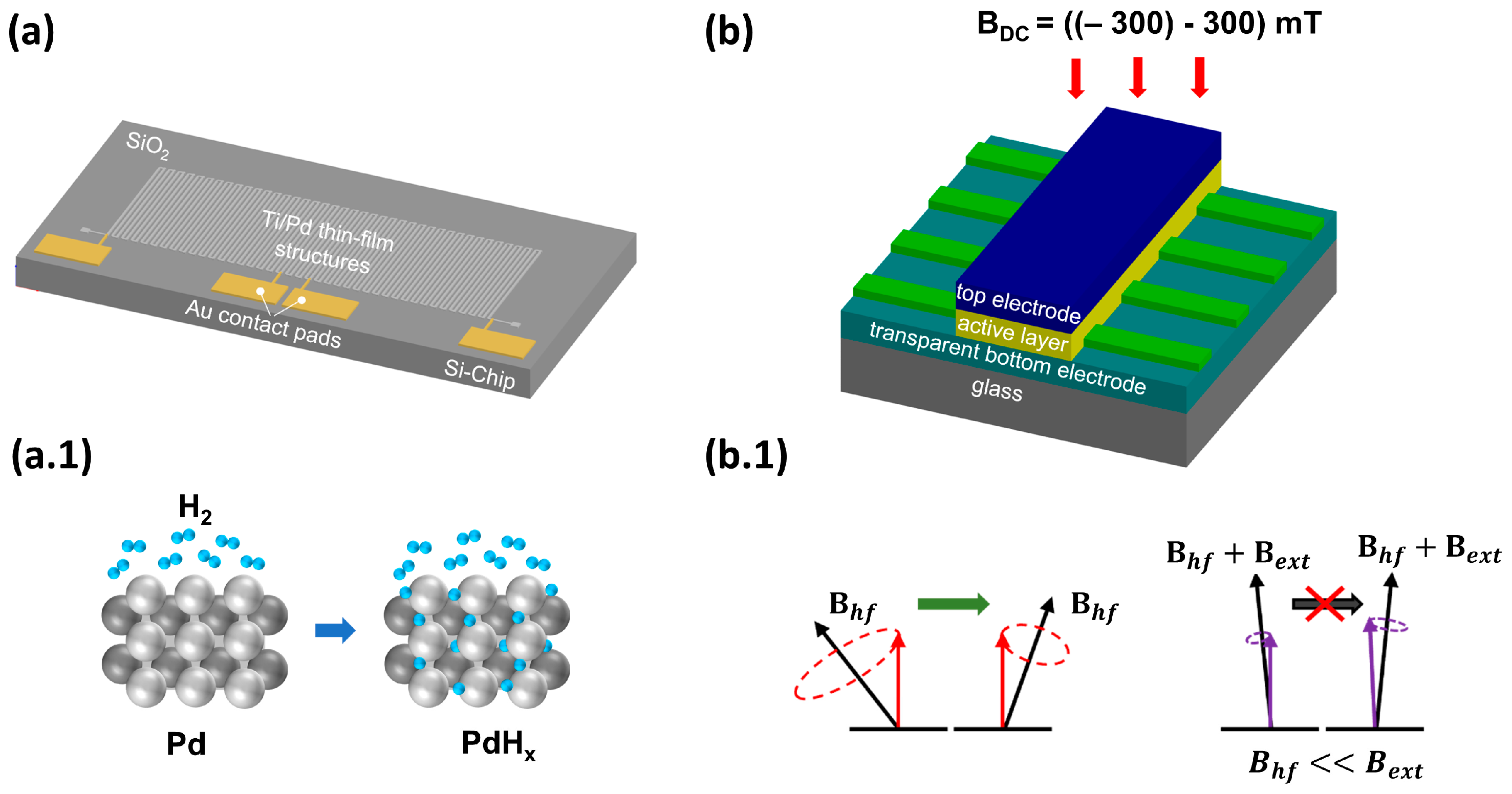
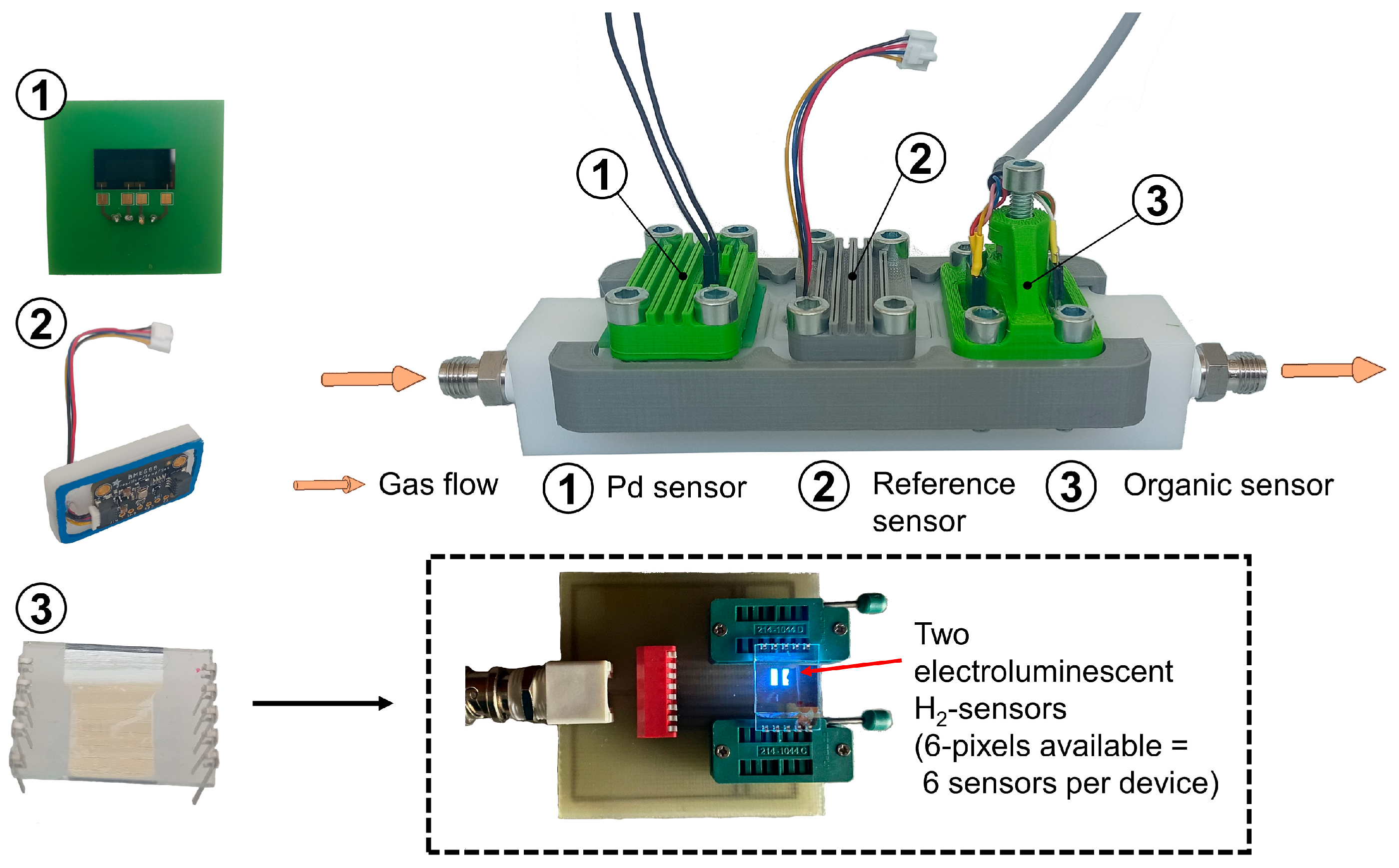
On the one hand, we are focusing on optimizing a hydrogen sensor based on the sensitive metal palladium, whose properties with regard to hydrogen are well known and have been largely characterized [67]. We are specifically investigating the potential of thin palladium layers as a sensor element for use on the anode side within the fuel cell. For this reason, we characterize different palladium thin-film structures within the operating parameters of a PEMFC. The sensing principle for measuring the H2 concentration is based on the formation of palladium hydride (PdHx) and the associated decrease in electrical conductivity [68]. First, the hydrogen molecules adsorb onto the Pd surface and dissociate into two hydrogen atoms. These atoms can diffuse into the interstitial sites of the metal lattice (see Figure 2a.1), forming PdHx and reducing free electron movement because of electron-scattering effects [41,69]. To use these effects in an H2-sensitive sensor, thin-film structures of SiO2, titanium and palladium are manufactured on 6″ silicon wafers using photolithographic techniques, including a combination of thin-film deposition methods, such as Physical Vapor Deposition (PVD) and lift-off processes based on photoresists. These structures (see Figure 2a) are then separated, applied onto a printed circuit board (PCB) and integrated into a hydrogen test chamber (see Figure 3).
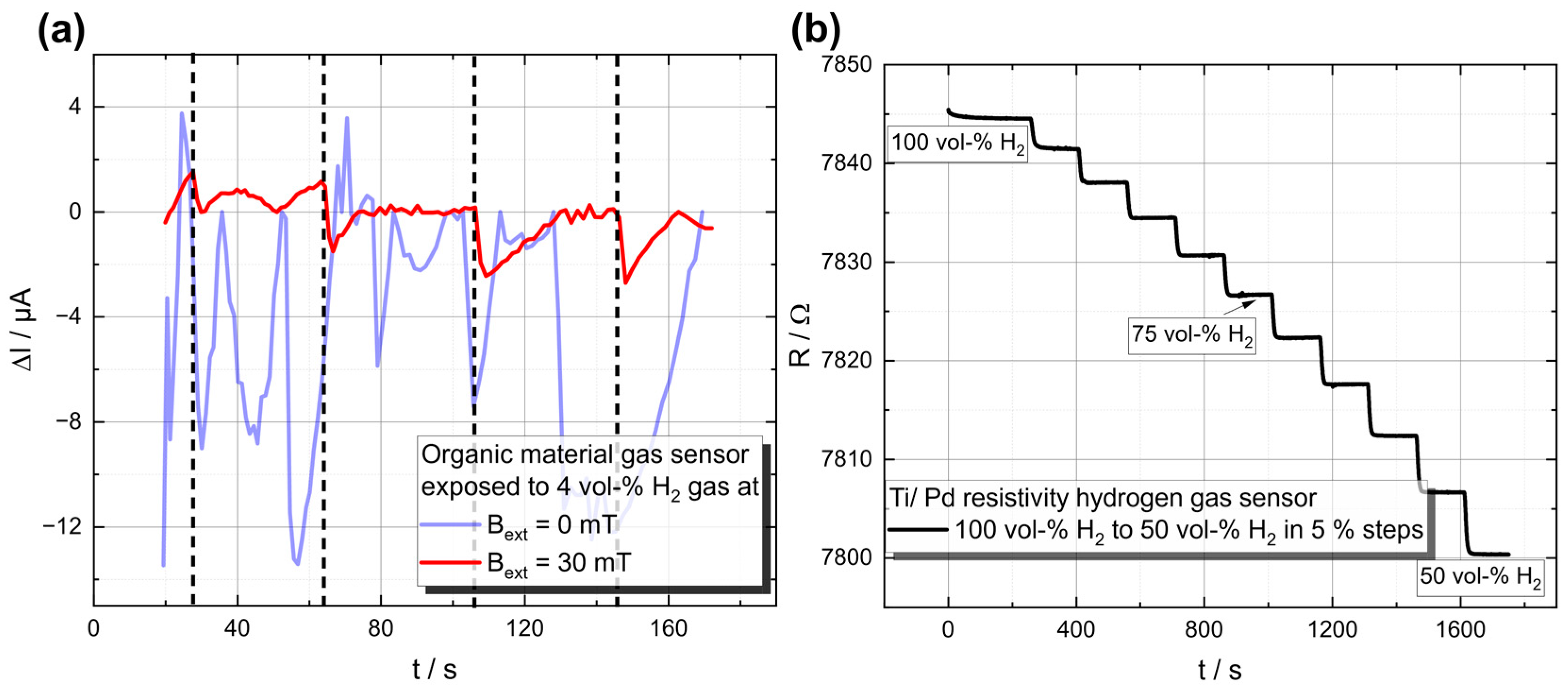
Initial measurements at different hydrogen concentrations from 50 to 100 vol-% in N2 carrier gas show a noticeable increase or decrease in electrical resistance depending on the H2 concentration (see Figure 4b).
The results confirm the working principle and show the considerable potential of these thin-film structures.
A Wheatstone bridge consisting of four sensor elements is required to compensate for temperature variations. Since two of the sensor elements must be protected against hydrogen diffusion, we characterize different barrier layers for their integrability with the Pd thin-film structures and their influence on hydrogen diffusion. The focus is on silicon nitride (Si3N4), silicon carbide (SiC), aluminum oxide (Al2O3) and a combination of these three materials, as they have a very low hydrogen permeability [70,71]. In addition, an encapsulation is being sought that protects the structure from humidity but does not significantly impair hydrogen diffusion.
The diffusion of hydrogen in palladium also leads to a volume expansion that causes stresses between the metal layers and the SiO2 substrate. These stresses can have a negative effect on both hydrogen diffusion [72,73] and the structural durability of the metal layers. In order to reduce these stresses and the associated effects, more flexible substrates are used in addition to SiO2. For this purpose, a process has been developed in which Pd thin-film structures can be deposited on Parylene. The structures produced in this way will be characterized and compared with the Pd structures on SiO2.
On the other hand, hydrogen sensors based on the phenomenon of organic magnetic field effects (MFEs) will be investigated according to their advantages, such as low production costs, flexibility, customizable geometry and high suitability for miniaturization [74,75]. MFEs arise when an external magnetic field influences the conductivity, resistivity or electroluminescence (in the case of OLED structures) of an organic device. Depending on the chosen organic material, this effect can result in either an increase or a decrease in the variable of interest when a weak external magnetic field is applied (Bext = ±300 mT, MFE(%) = (X(B) − X(B = 0 mT))/X(B = 0 mT), where X represents the variable of interest, e.g., conductivity or resistivity); see, e.g., [76]. According to the literature, such effects are only observed in the presence of hydrogen atoms [77]. This phenomenon is attributed to the hyperfine interaction originating from the coupling of a polaron (=a quasiparticle consisting of an electron/hole and its polarized environment) to the spins of hydrogen protons. Two charges of equal sign can form an intermediate state, a polaron pair or bipolaron. The singlet and triplet polaron pair formation rate alters in the presence of an external magnetic field; see, e.g., ref. [76]. While the device is exposed to hydrogen, it is assumed that more hydrogen atoms are present, while the bipolaron formation rate changes, and consequently the conductivity and electroluminescence change. TADF materials are well known for their excellent MFE response (see, e.g., ref. [78]) and for their high external quantum efficiencies, suggesting a lower power consumption compared to other organic materials, e.g., small molecules and/or polymers [79].
The working principle of an organic-based hydrogen sensor is depicted in Figure 2b. The layer stack contains an organic active layer, e.g., a TADF material (cf. [80]), which further emits light (cf. Figure 3). This light emission serves a dual purpose: it acts as a measurable parameter to monitor the influence of hydrogen, and it also provides a direct indication that the device is functioning properly. The device structure is based on a vertical stacking geometry, similar to an OLED structure, to achieve a high magnetic flux. The device is exposed to hydrogen gas, as displayed in Figure 3, with an adjustable magnet mounted on top to control the external magnetic field. The current through the device is measured, where an additional difference (next to the applied magnetic field) is expected upon the hydrogen concentration, originating from the altered bipolaron formation rate (cf. Figure 2b.1). Initial measurements, which can be found in Figure 4b, at a hydrogen concentration of 4 vol-% in N2 carrier gas demonstrate the fundamental working principle. Only when an external magnetic field was applied to the device a decrease in the current upon hydrogen gas injection was detected. As can be seen in Figure 4b, the signal-to-noise ratio is relatively high for this test device. We propose two improvement strategies to address this issue: (1) Investigation of the encapsulant material. It is crucial to balance the high gas permeability for H2 [81] with low permeability for O2 and H2O [82,83]. Potential materials suiting those needs include parylene, poly(methyl methacrylate) (PMMA) and polydimethylsiloxane (PDMS); see ref. [84] for a review on encapsulation technologies for organic electronic devices. (2) Increasing the reactive surface area, which can be achieved by structuring the top electrode to enhance the contact area between hydrogen and the organic material, resulting in an increased measurable response. To operate organic-based sensors in a real fuel cell stack, it is essential to demonstrate suitable temperature stability at 80 °C. In the past, organic solar cells faced similar challenges related to their usage, e.g., cars, building fronts and roofs, but these issues have long been addressed and organic solar cells are commercially available. It is well known that high temperatures can increase structural defects, bubbles and dark spots, leading to a decrease in device lifetime. Various aspects of OLED stability and degradation mechanisms are discussed in a recent review [85]. Tokito et al. showed that the critical temperature at which significant degradation occurs is related to the glass transition temperature, Tc. They demonstrated that stable devices can be built to withstand temperatures up to 150 °C. Therefore, we suggest using materials with a high glass transition temperature, which can result in a longer device lifetime, such as 5′-(4-(4,6-diphenyl-1,3,5-triazine-2-yl) phenyl)− 5′H-spiro[fluorene-9,8′-indeno [2,1-c] carbazole] (4-SCZ) (180 °C), 5′-(4-(4,6-diphenyl-1,3,5-triazine-2-yl)-2-fluorophenyl)-5′H-spiro [fluorene-9,8′-indeno [2,1-c] carbazole] (4SCZ-F) (197 °C) [86] and 3-(N,N-Diphenylamino)carbazole (~170 °C) [87]. On the other hand, other studies, such as those by Adachi et al., do not fully support this theory. They found that several materials with a low glass transition temperature exhibited no direct correlation of the Tc with the device durability. It was argued instead that good band alignment is crucial for minimizing device degradation. Therefore, further research is needed to understand the interplay between the Tc, band alignment and device stability and to find optimal materials/material combinations for hydrogen sensing devices.

4.2. Sensor Integration

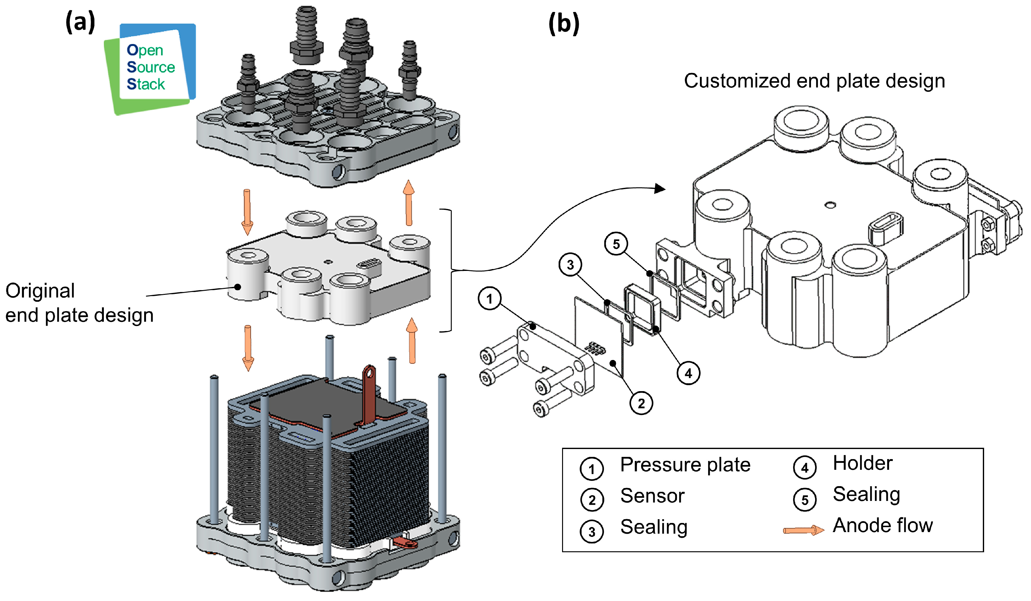
The concepts for sensor integration are developed on the basis of the experimental research platform ‘Open-Source Stack’ (OSS), which was designed and set up in house [88]. The aim is to create an initial test setup (with hydrogen sensors integrated into the stack) which can then be used to identify possibilities for further optimization. At the current stage of development, the sensors require a significant amount of installation space due to their size. For this reason, when comparing suitable components of the OSS for integration, the end plate of the fuel cell stack, which conducts media in and out of the stack, proved to be particularly appropriate for the integration of sensors of such proportions. The end plate provides sufficient installation space, good access to the anode flow channels and easy adaptability without affecting the medium flow inside the fuel cell. The integration into the end plate of the stack also enables measurements to be taken close to the cells of the stack. Figure 5a shows the basic structure of the OSS. The end plate in its original design is highlighted. As shown, as an example, in Figure 5b, integration could be achieved by increasing the thickness of the end plate and creating access to the media channels. Additionally, suitable mounting elements would need to be designed to ensure that the sensor’s active surface contacts the medium effectively, while appropriate sealing elements ensure a secure and tight fit, exemplarily depicted in Figure 5b. The sensors could simply be attached to the corresponding connection points.
However, integrating the sensors into the end plate means that only the entire stack can be analyzed, not the individual cells. The hydrogen concentration can only be measured at the inlet and outlet. Reducing the size in future versions, the bipolar plates of the stack would also be particularly interesting for integration. This would allow measurements to be made within individual cells of the stack, analyzing the differences between certain areas.
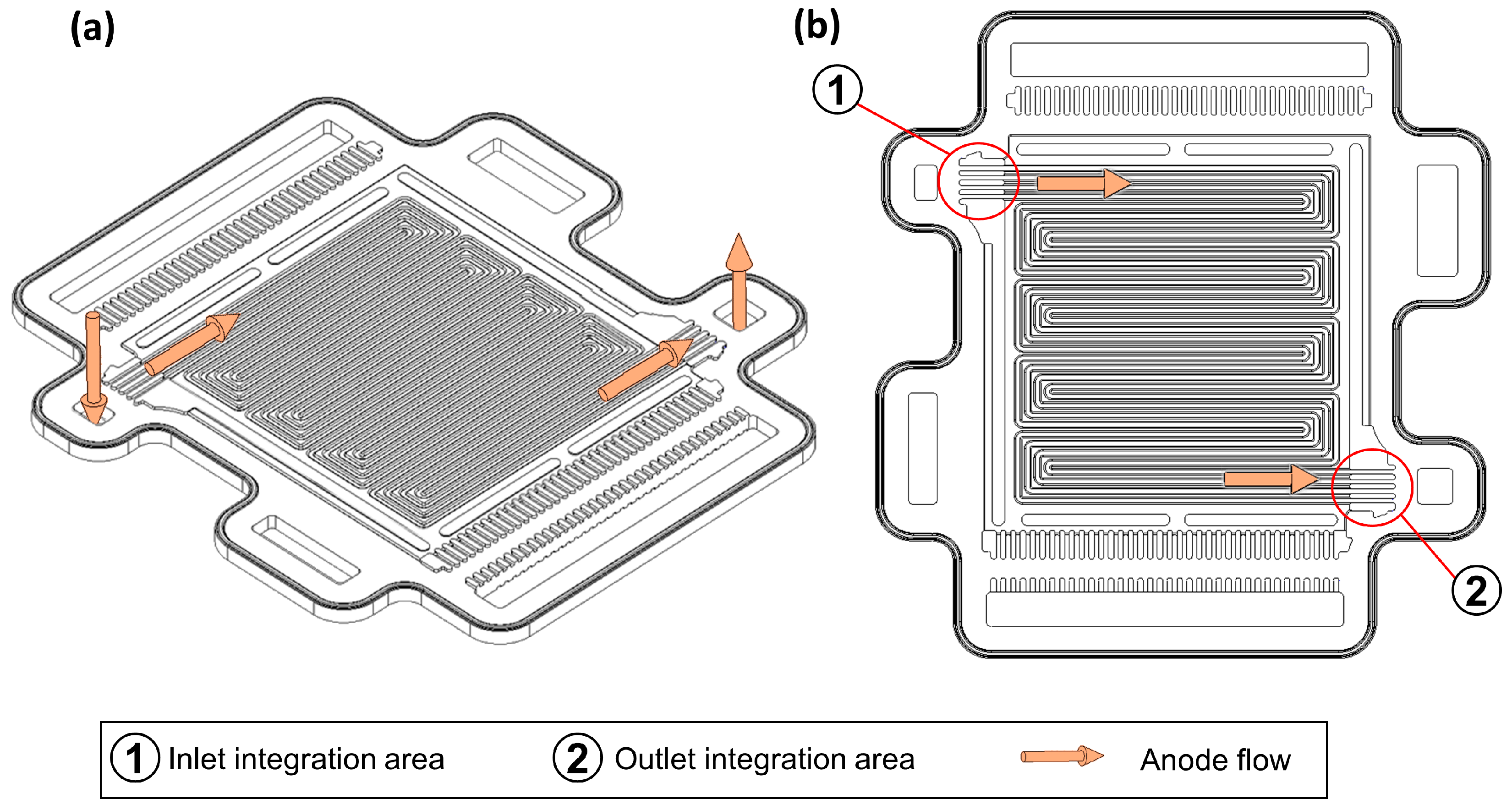
In order to integrate the sensors into the bipolar plate, the sensors must be further reduced in size to meet the requirements. Furthermore, the tightness of the stack must not be impaired by the electrical connections leading to the outside, and the gas flow must not be negatively affected by the integrated sensors. According to the current state of the art, sensor integration concepts for bipolar plates [12] and gas diffusion layers [89] have already been worked on. Figure 6 shows an anode bipolar plate of the OSS and the corresponding flow field.
As shown in Figure 6b, based on the bipolar plate design of the OSS, further correspondingly developed sensor versions could be integrated into the bipolar plate in the area of the anode inlet and outlet of each single cell.

4.3. Enhancement of Data Analysis to Increase Computational Efficiency

In contrast to the palladium-based sensor (where the hydrogen concentration is directly a function of the ohmic resistance), for the organic sensor approach, the hydrogen concentration is parameterized by the magnetic field. An important question is how many measurements with different magnetic field strengths are necessary to determine the correct hydrogen concentration. By using subsampling strategies, the number of measurements with different magnetic field strengths are reduced. This influences the lifetime of the sensor, since fewer measurements with fast changing magnetic field strengths are necessary. Instead of reducing the number of measurements, subsampling strategies could also be used to increase the overall measurement rate by reducing the number of necessary measurements with different magnetic field strengths while keeping the overall amount of measurements constant. The challenge is to find as few data points as possible while still providing enough information for reliable control. Mathematical theories provide multiple different approaches, such as sparse recovery from compressed sensing [90], subsampling strategies from information-based complexity [91,92,93,94] and reconstruction via random measurements [95]. By reducing the number of measurements, the damage to sensors can be reduced. Hence, we aim to use recent advancements in compressed sensing and information-based complexity, in particular, subsampling strategies as developed in [94], and apply them to our problem of optimal measuring. Thus, the task is to find as few data points as possible that still provide enough information for reliable control.
The algorithm in detail works as follows: we take sample values which are modelled in an abstract space (describing temperature, pressure, conductivity, magnetic field effects, etc.) and use these to recover a function via a least-squares approximation, which in turn gives us our desired values (concentration, partial pressure, etc.). The precise relation between the function and the values remains to be determined, also via real-world measurements.
This theory is still relatively new and, to our knowledge, has not yet been applied to engineering problems. It remains to analyze its applicability to our research question and to adapt it for our purposes. In this compressed sensing problem, we have three spaces of parameters: X , Y and Z . Here, X is the space of parameters that we need for the measurements (magnetic field strength, voltage, etc.), Y is the set of parameters we measure (electroluminescence, electric resistivity, etc.) and Z is the set of parameters that determine the state of the gas (hydrogen concentration/pressure, etc.). A measurement is then a function f : X Y , where f = f z depends on the state of the gas z Z . We want to reconstruct f (to obtain the state z ) via samples of f . Taking N measurements and keeping possible measurement errors in mind, we obtain measurements x i , f ~ x i i = 1 N and want to find that f = f z which minimizes the error i = 1 N f x i f ~ x i 2 with respect to Z (or some other suitable notion of error). Obviously, taking more measurements will give us a more reliable reconstruction of f at the cost of higher degradation of the components. Thus, we need to find the smallest possible set of nodes x i to sample that will still give us good reconstruction guarantees. One way to do this is to choose a random set of N nodes and apply algorithms from [92] to find a subset of size ~ N log N that still reliably gives good reconstructions. Thus, during the course of the project, we need to extract the smallest set of parameters that will matter (to reduce the dimension of the problem f : X Y , improving reconstruction rates) and determine good sample points along the way.

4.4. Development of Advanced Fuel Cell Control

Due to challenges in recalculating the amount of hydrogen inside a fuel cell stack based on the fuel cell voltage model with non-linearities, hysteresis effects and model inaccuracies, as well as temperature and humidity dependencies in the polarization curve, indirect fuel cell control based on stoichiometries fails during fast load changes [54].
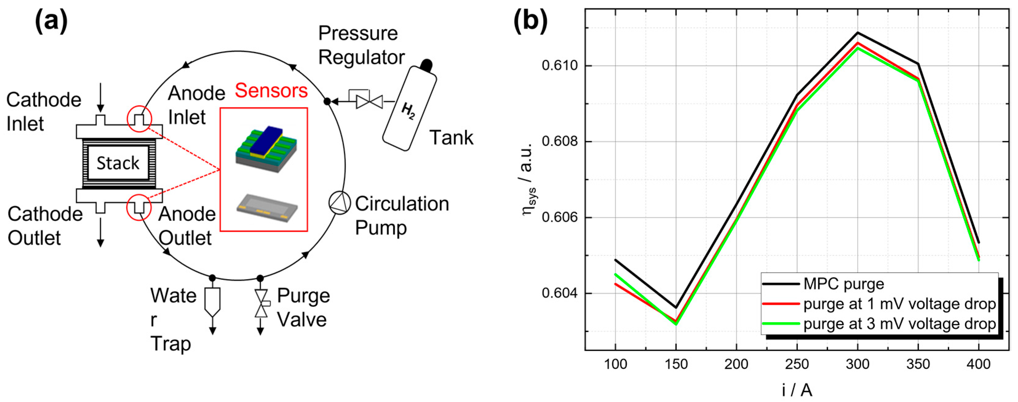
By integrating hydrogen sensors in a fuel cell system, as presented in Figure 7a, frequent measurements of the hydrogen concentration are possible, thus allowing for direct hydrogen control (instead of indirect hydrogen control via voltage). This circumvents the above-mentioned problems of recalculating the amount of hydrogen inside the fuel cell stack. Therefore, the hydrogen value is more precise and directly available. Since the presented sensors have a response time of around 5 s, a dynamic sensor model is used to evaluate the sensor output at a higher frequency. The sensor is modeled as a gain-scheduled PT1-system with a varying gain constant, K . As can be seen in Figure 4b, the time constant of the sensor response is constantly 5 s over the entire range, while the gain increases with reduced hydrogen concentration.
A wide range of controllers, from simple PID controllers [56] up to adaptive and model-based controllers [2,54], could be applied to control the hydrogen present in the fuel cell for the chemical reaction. While PID controllers have the advantage of simple implementation, optimal control approaches like model predictive control offer improved fuel cell system efficiency and guarantee constraint satisfaction, such that sufficient hydrogen is present in the fuel cell for the chemical reaction and fuel starvation is avoided at all times. In contrast to classical stoichiometry-based fuel cell control strategies, fuel starvation (e.g., due to the absence of hydrogen during fast load changes) can be avoided even in the presence of other impurities.
In addition to controlling the hydrogen concentration inside the fuel cell, hydrogen sensors could also be used to enhance the control of the purge valve. Commonly, the purge valve is opened after a certain voltage drop or at a higher regular frequency to avoid this drop, resulting in a higher loss of unconsumed hydrogen. With precise knowledge of the hydrogen concentration, the purge valve can be opened before the reduction in hydrogen results in a voltage drop and avoid unnecessary purge valve openings, reducing the loss of unconsumed hydrogen. Studies have shown that a model predictive control (MPC) approach with actual hydrogen measurements has the potential to outperform standard purge approaches, resulting in a higher system efficiency along the complete operating range of the fuel cell system (see Figure 7b) while guaranteeing a limited amount of impurities in the anode [9].
Furthermore, the performance of the recirculation pump in the anode loop depends on the gas concentrations [96]. Hydrogen measurements can be used to control the recirculation pump more precisely, which is important for the durability and stability of the fuel cell system [2].

5. Conclusions and Outlook

This perspective paper reviews current hydrogen sensor technologies and their applications in fuel cell control. Most existing sensors require oxygen, are moisture-sensitive, or need extensive setups, and typically detect hydrogen concentrations from a few parts per million to 4 vol-%. Nevertheless, there is a lack of sensors that can detect a high hydrogen concentration (up to 100 vol-%) in the anode circuit of fuel cells, which is a major challenge due to the lack of oxygen, high humidity (up to 100%) and limited space.
We explore two novel sensor approaches: a resistive sensor using palladium and an organic material-based sensor leveraging the organic magnetic field effect. Prototypes and a test chamber have been developed to validate these sensors under fuel cell conditions—no oxygen, high humidity, temperatures up to 80 °C and high hydrogen concentrations. The prototypes show the potential to detect hydrogen through conductivity and electroluminescence of the organic material or resistance measurements on palladium thin films. A Wheatstone bridge comprising four sensor elements can be used to compensate for temperature variations. The efficacy of a variety of barrier materials has been evaluated.
We propose integrating these sensors into the anode loop by modifying the fuel cell stack’s end plate at the anode gas flow points. The analysis includes enhancing data processing to improve efficiency, extend sensor lifespan, and optimize hydrogen control. Effective hydrogen measurements could boost fuel cell performance by refining hydrogen flow control and optimizing purge valves and recirculation pumps, thereby increasing efficiency, durability and stability. It is essential to protect sensors in PEMFCs from high relative humidity. Polymers are the solution, offering the best balance of hydrogen permeability and water resistance.

Author Contributions

Conceptualization, M.H. and A.S.; methodology, M.H. and L.V.; software, R.T., N.N., A.M. and C.B.; validation, C.B., A.M. and L.V.; formal analysis, N.N.; investigation, C.B., A.M., C.R.M. and L.V.; resources, H.K., T.v.U. and G.S.; data curation, C.R.M.; writing—original draft preparation, M.H., C.B., A.M., N.N. and R.T.; writing—review and editing, M.H., A.M., C.B., A.S., G.S. and S.S.; visualization, A.M. and L.V.; supervision, H.K., G.S., D.S., T.U., T.v.U. and S.S.; project administration, T.U.; funding acquisition, H.K., G.S., D.S., T.U., T.v.U. and S.S. All authors have read and agreed to the published version of the manuscript.

Funding

This work was part of the research project ReSIDA-H2 and was funded by the European Union, European Social Fund ESF-Plus, Saxony.

Data Availability Statement

Data are contained within the article.

Conflicts of Interest

The authors declare no conflicts of interest. The funders had no role in the design of the study; in the collection, analyses or interpretation of data; in the writing of the manuscript; or in the decision to publish the results.

References

  1. Morán-Durán, A.; Martínez-Sibaja, A.; Rodríguez-Jarquin, J.P.; Posada-Gómez, R.; González, O.S. PEM Fuel Cell Voltage Neural Control Based on Hydrogen Pressure Regulation. Processes 2019, 7, 434. [Google Scholar] [CrossRef]
  2. He, H.; Quan, S.; Wang, Y.-X. Hydrogen Circulation System Model Predictive Control for Polymer Electrolyte Membrane Fuel Cell-Based Electric Vehicle Application. Int. J. Hydrogen Energy 2020, 45, 20382–20390. [Google Scholar] [CrossRef]
  3. Tian, Y.; Zou, Q.; Lin, Z. Hydrogen Leakage Diagnosis for Proton Exchange Membrane Fuel Cell Systems: Methods and Suggestions on Its Application in Fuel Cell Vehicles. IEEE Access 2020, 8, 224895–224910. [Google Scholar] [CrossRef]
  4. Hauck, M.; Petzke, F.; Tafat, R.; Streif, S. Observability Analysis of PEM Fuel Cell Systems with Anode Recirculation. In Proceedings of the 2024 European Control Conference (ECC), Stockholm, Sweden, 25–28 June 2024; pp. 2423–2428. [Google Scholar]
  5. Tang, Q.; Li, B.; Yang, D.; Ming, P.; Zhang, C.; Wang, Y. Review of Hydrogen Crossover through the Polymer Electrolyte Membrane. Int. J. Hydrogen Energy 2021, 46, 22040–22061. [Google Scholar] [CrossRef]
  6. Tang, X.; Yang, M.; Shi, L.; Hou, Z.; Xu, S.; Sun, C. Adaptive State-of-Health Temperature Sensitivity Characteristics for Durability Improvement of PEM Fuel Cells. Chem. Eng. J. 2024, 491, 151951. [Google Scholar] [CrossRef]
  7. Quan, S.; Wang, Y.-X.; Xiao, X.; He, H.; Sun, F. Feedback Linearization-Based MIMO Model Predictive Control with Defined Pseudo-Reference for Hydrogen Regulation of Automotive Fuel Cells. Appl. Energy 2021, 293, 116919. [Google Scholar] [CrossRef]
  8. Liu, Z.; Chen, J.; Liu, H.; Yan, C.; Hou, Y.; He, Q.; Zhang, J.; Hissel, D. Anode Purge Management for Hydrogen Utilization and Stack Durability Improvement of PEM Fuel Cell Systems. Appl. Energy 2020, 275, 115110. [Google Scholar] [CrossRef]
  9. Hauck, M.; Petzke, F.; Streif, S. Model Predictive Purge Control for PEM Fuel Cell Systems with Anode Recirculation. In Proceedings of the 60th IEEE Conference on Decision and Control, Austin, TX, USA, 14–17 December 2021; IEEE: Piscataway, NJ, USA, 2021; pp. 6359–6364. [Google Scholar]
  10. Tang, Y.-Q.; Fang, W.-Z.; Lin, H.; Tao, W.-Q. Thin Film Thermocouple Fabrication and Its Application for Real-Time Temperature Measurement inside PEMFC. Int. J. Heat Mass Transf. 2019, 141, 1152–1158. [Google Scholar] [CrossRef]
  11. Wagner, E. Das System Brennstoffzelle: Wasserstoffsysteme Ganzheitlich Entwickeln; Hanser: Munich, Germany, 2023; ISBN 3-446-47505-2. [Google Scholar]
  12. Muck, N.; David, C. Integrating Fiber Sensing for Spatially Resolved Temperature Measurement in Fuel Cells. Energies 2023, 17, 16. [Google Scholar] [CrossRef]
  13. Awang, Z. Gas Sensors: A Review. Sens Transducers 2014, 168, 61–75. [Google Scholar]
  14. Lee, E.-B.; Hwang, I.-S.; Cha, J.-H.; Lee, H.-J.; Lee, W.-B.; Pak, J.J.; Lee, J.-H.; Ju, B.-K. Micromachined Catalytic Combustible Hydrogen Gas Sensor. Sens. Actuators B Chem. 2011, 153, 392–397. [Google Scholar] [CrossRef]
  15. Honeywell Model 705 HT Sensor. Available online: https://prod-edam.honeywell.com/content/dam/honeywell-edam/sps/his/it-it/products/gas-and-flame-detection/documents/hwa6110_h_model_705_high_temperature_sensor_ds0301_v3_flr_6_29_10.pdf?download=false (accessed on 11 September 2024).
  16. Samari, R. Low Power Combustible Gas Sensors. U.S. Patent 7,833,482 B2, 16 November 2010. Available online: https://patentimages.storage.googleapis.com/80/28/dc/9bbdd279400d25/US7833482.pdf (accessed on 11 September 2024).
  17. Pranti, A.S.; Loof, D.; Kunz, S.; Zielasek, V.; Bäumer, M.; Lang, W. Design and Fabrication Challenges of a Highly Sensitive Thermoelectric-Based Hydrogen Gas Sensor. Micromachines 2019, 10, 650. [Google Scholar] [CrossRef] [PubMed]
  18. FIGARO TGS 821—Special Sensor for Hydrogen Gas. Available online: https://Www.Figarosensor.Com/Product/Docs/TGS821.Pdf2024 (accessed on 11 September 2024).
  19. Ji, H.; Zeng, W.; Li, Y. Gas Sensing Mechanisms of Metal Oxide Semiconductors: A Focus Review. Nanoscale 2019, 11, 22664–22684. [Google Scholar] [CrossRef] [PubMed]
  20. Phanichphant, S. Semiconductor Metal Oxides as Hydrogen Gas Sensors. Procedia Eng. 2014, 87, 795–802. [Google Scholar] [CrossRef]
  21. Trinchi, A.; Kandasamy, S.; Wlodarski, W. High Temperature Field Effect Hydrogen and Hydrocarbon Gas Sensors Based on SiC MOS Devices. Sens. Actuators B Chem. 2008, 133, 705–716. [Google Scholar] [CrossRef]
  22. Currie, J.F.; Essalik, A.; Marusic, J. Micromachined Thin Film Solid State Electrochemical CO2, NO2 and SO2 Gas Sensors. Sens. Actuators B Chem. 1999, 59, 235–241. [Google Scholar] [CrossRef]
  23. EC Sense ES1-H2-5%. 2024. Available online: https://Ecsense.Com/Product/Es1-H2-5-Hydrogen-Gas-Sensor/ (accessed on 11 September 2024).
  24. Posifa Technologies MEMS THERMAL CONDUCTIVITY HYDROGEN SENSORS. Available online: https://posifatech.com/wp-content/uploads/2020/11/Datasheet_PGS1000_MEMS_TC_H2_RevA_C0.5.pdf (accessed on 11 September 2024).
  25. De Graaf, G.; Wolffenbuttel, R. Surface-Micromachined Thermal Conductivity Detectors for Gas Sensing. In Proceedings of the 2012 IEEE International Instrumentation and Measurement Technology Conference Proceedings, Graz, Austria, 13–16 May 2012; pp. 1861–1864. [Google Scholar]
  26. Tu, X.Z. Single Silicon Wafer Micromachined Thermal Conduction Sensor. U.S. Patent 9,580,305 B2, 28 February 2017. Available online: https://patentimages.storage.googleapis.com/34/71/6f/50dc76a7453f1d/US9580305.pdf (accessed on 11 September 2024).
  27. Hübert, T.; Boon-Brett, L.; Black, G.; Banach, U. Hydrogen Sensors–a Review. Sens. Actuators B Chem. 2011, 157, 329–352. [Google Scholar] [CrossRef]
  28. Yu, Z.; Berding, M.; Krishnamurthy, S. Spin Transport in Organics and Organic Spin Devices. IEE Proc.-Circuits Devices Syst. 2005, 152, 334–339. [Google Scholar] [CrossRef]
  29. Liu, K.; Ouyang, B.; Guo, X.; Guo, Y.; Liu, Y. Advances in Flexible Organic Field-Effect Transistors and Their Applications for Flexible Electronics. Npj Flex. Electron. 2022, 6, 1. [Google Scholar] [CrossRef]
  30. Rath, R.J.; Farajikhah, S.; Oveissi, F.; Dehghani, F.; Naficy, S. Chemiresistive Sensor Arrays for Gas/Volatile Organic Compounds Monitoring: A Review. Adv. Eng. Mater. 2023, 25, 2200830. [Google Scholar] [CrossRef]
  31. Chunhong, D.; Guangzhong, X.; Junsheng, Y. Fabrication and Properties of an OLED-Based Gas Sensor with ZnPc Sensing Film. In Proceedings of the IEEE 10th International Conference on Electronic Measurement & Instruments, Chengdu, China, 16–19 August 2011; Volume 1, pp. 164–167. [Google Scholar]
  32. Xie, G.; Jiang, Y.; Du, X.; Tai, H.; Li, W. P1. 8.8 Fabrication and Properties of an OLED-Based Gas Sensor with Poly (3-Hexylthiophene) Sensing Film. In Proceedings of the 14th International Meeting on Chemical Sensors—IMCS 2012, Nuremberg, Germany, 20–23 May 2012; pp. 1130–1133. [Google Scholar]
  33. Adachi, C.; Xie, G.; Reineke, S.; Zysman-Colman, E. Recent Advances in Thermally Activated Delayed Fluorescence Materials. Front. Chem. 2020, 8, 625910. [Google Scholar] [CrossRef] [PubMed]
  34. He, J.; Yan, X.; Liu, A.; You, R.; Liu, F.; Li, S.; Wang, J.; Wang, C.; Sun, P.; Yan, X. A Rapid-Response Room-Temperature Planar Type Gas Sensor Based on DPA-Ph-DBPzDCN for the Sensitive Detection of NH 3. J. Mater. Chem. A 2019, 7, 4744–4750. [Google Scholar] [CrossRef]
  35. He, J.; Liang, B.; Yan, X.; Liu, F.; Wang, J.; Yang, Z.; You, R.; Wang, C.; Sun, P.; Yan, X. A TPA-DCPP Organic Semiconductor Film-Based Room Temperature NH3 Sensor for Insight into the Sensing Properties. Sens. Actuators B Chem. 2021, 327, 128940. [Google Scholar] [CrossRef]
  36. Kalita, A.; Hussain, S.; Malik, A.H.; Subbarao, N.V.; Iyer, P.K. Vapor Phase Sensing of Ammonia at the Sub-Ppm Level Using a Perylene Diimide Thin Film Device. J. Mater. Chem. C 2015, 3, 10767–10774. [Google Scholar] [CrossRef]
  37. Li, L.; Gao, P.; Baumgarten, M.; Müllen, K.; Lu, N.; Fuchs, H.; Chi, L. High Performance Field-effect Ammonia Sensors Based on a Structured Ultrathin Organic Semiconductor Film. Adv. Mater. 2013, 25, 3419–3425. [Google Scholar] [CrossRef]
  38. Xiao, X.; Cheng, X.; Hou, X.; He, J.; Xu, Q.; Li, H.; Li, N.; Chen, D.; Lu, J. Ion-in-conjugation: Squaraine as an Ultrasensitive Ammonia Sensor Material. Small 2017, 13, 1602190. [Google Scholar] [CrossRef]
  39. Zang, Y.; Zhang, F.; Huang, D.; Di, C.; Meng, Q.; Gao, X.; Zhu, D. Specific and Reproducible Gas Sensors Utilizing Gas-phase Chemical Reaction on Organic Transistors. Adv. Mater. 2014, 26, 2862–2867. [Google Scholar] [CrossRef]
  40. Shin, W.; Matsumiya, M.; Qiu, F.; Izu, N.; Murayama, N. Thermoelectric Gas Sensor for Detection of High Hydrogen Concentration. Sens. Actuators B Chem. 2004, 97, 344–347. [Google Scholar] [CrossRef]
  41. Koo, W.-T.; Cho, H.-J.; Kim, D.-H.; Kim, Y.H.; Shin, H.; Penner, R.M.; Kim, I.-D. Chemiresistive Hydrogen Sensors: Fundamentals, Recent Advances, and Challenges. ACS Nano 2020, 14, 14284–14322. [Google Scholar] [CrossRef]
  42. Pei, Y.; Chen, F.; Jiao, J.; Liu, S. Analysis and Control Strategy Design for PEMFC Purging Process. Energy 2024, 290, 130233. [Google Scholar] [CrossRef]
  43. Gao, Y.; Lin, M. Research on the Performance Characteristics of Hydrogen Circulation Pumps for PEMFC Vehicles. Int. J. Hydrogen Energy 2023, 50, 1255–1272. [Google Scholar] [CrossRef]
  44. Lee, Y.-A.; Han, S.; An, H.; Park, J.; Singh, R.; Kim, H.Y.; Seo, H. Confined Interfacial Alloying of Multilayered Pd-Ni Nanocatalyst for Widening Hydrogen Detection Capacity. Sens. Actuators B Chem. 2021, 330, 129378. [Google Scholar] [CrossRef]
  45. Gong, J.; Wang, Z.; Tang, Y.; Sun, J.; Wei, X.; Zhang, Q.; Tian, G.; Wang, H. MEMS-Based Resistive Hydrogen Sensor with High Performance Using a Palladium-Gold Alloy Thin Film. J. Alloys Compd. 2023, 930, 167398. [Google Scholar] [CrossRef]
  46. Yoon, J.-H.; Kim, B.-J.; Kim, J.-S. Design and Fabrication of Micro Hydrogen Gas Sensors Using Palladium Thin Film. Mater. Chem. Phys. 2012, 133, 987–991. [Google Scholar] [CrossRef]
  47. Hoffmann, M.; Wienecke, M.; Lengert, M.; Weidner, M.H.; Heeg, J. Palladium Based Mems Hydrogen Sensors. In Proceedings of the 2023 IEEE 36th International Conference on Micro Electro Mechanical Systems (MEMS), Munich, Germany, 15–19 January 2023; pp. 822–825. [Google Scholar]
  48. Wu, H.; Kustra, S.; Gates, E.M.; Bettinger, C.J. Topographic Substrates as Strain Relief Features in Stretchable Organic Thin Film Transistors. Org. Electron. 2013, 14, 1636–1642. [Google Scholar] [CrossRef]
  49. Yan, H.; Chen, Z.; Zheng, Y.; Newman, C.; Quinn, J.R.; Dötz, F.; Kastler, M.; Facchetti, A. A High-Mobility Electron-Transporting Polymer for Printed Transistors. Nature 2009, 457, 679–686. [Google Scholar] [CrossRef]
  50. Siegel, A.C.; Phillips, S.T.; Dickey, M.D.; Lu, N.; Suo, Z.; Whitesides, G.M. Foldable Printed Circuit Boards on Paper Substrates. Adv. Funct. Mater. 2010, 20, 28–35. [Google Scholar] [CrossRef]
  51. Sasabe, H.; Kido, J. Development of High Performance OLEDs for General Lighting. J. Mater. Chem. C 2013, 1, 1699–1707. [Google Scholar] [CrossRef]
  52. Kaltenbrunner, M.; White, M.S.; Głowacki, E.D.; Sekitani, T.; Someya, T.; Sariciftci, N.S.; Bauer, S. Ultrathin and Lightweight Organic Solar Cells with High Flexibility. Nat. Commun. 2012, 3, 770. [Google Scholar] [CrossRef]
  53. Kim, O.; Yoo, S.J.; Kim, J.Y.; Cho, S.K.; Park, H.S.; Lee, S.Y.; Seo, B.; Jang, J.H.; Lim, K.H.; Park, H.-Y. Impact of Fuel Starvation–Induced Anode Carbon Corrosion in Proton Exchange Membrane Fuel Cells on the Structure of the Membrane Electrode Assembly and Exhaust Gas Emissions: A Quantitative Case Study. J. Power Sources 2024, 615, 235032. [Google Scholar] [CrossRef]
  54. Yang, B.; Li, J.; Li, Y.; Guo, Z.; Zeng, K.; Shu, H.; Cao, P.; Ren, Y. A Critical Survey of Proton Exchange Membrane Fuel Cell System Control: Summaries, Advances, and Perspectives. Int. J. Hydrogen Energy 2022, 47, 9986–10020. [Google Scholar] [CrossRef]
  55. Wang, Y.; Zhang, H.; He, S.; Wang, W.; Gao, M.; Moiseevna, K.E.; Anatolievna, V.V. Dynamic Analysis and Control Optimization of Hydrogen Supply for the Proton Exchange Membrane Fuel Cell and Metal Hydride Coupling System with a Hydrogen Buffer Tank. Energy Convers. Manag. 2023, 291, 117339. [Google Scholar] [CrossRef]
  56. Li, X.; Qi, Y.; Li, S.; Tunestål, P.; Andersson, M. A Multi-input and Single-output Voltage Control for a Polymer Electrolyte Fuel Cell System Using Model Predictive Control Method. Int. J. Energy Res. 2021, 45, 12854–12863. [Google Scholar] [CrossRef]
  57. Kamal, E.; Aitouche, A. Fuzzy Observer-Based Fault Tolerant Control against Sensor Faults for Proton Exchange Membrane Fuel Cells. Int. J. Hydrogen Energy 2020, 45, 11220–11232. [Google Scholar] [CrossRef]
  58. Fu, H.; Shen, J.; Sun, L.; Lee, K.Y. In-Depth Characteristic Analysis and Wide Range Optimal Operation of Fuel Cell Using Multi-Model Predictive Control. Energy 2021, 234, 121226. [Google Scholar] [CrossRef]
  59. Mei, J.; Meng, X.; Tang, X.; Li, H.; Hasanien, H.; Alharbi, M.; Dong, Z.; Shen, J.; Sun, C.; Fan, F. An Accurate Parameter Estimation Method of the Voltage Model for Proton Exchange Membrane Fuel Cells. Energies 2024, 17, 2917. [Google Scholar] [CrossRef]
  60. Yuan, H.; Dai, H.; Wei, X.; Ming, P. Model-Based Observers for Internal States Estimation and Control of Proton Exchange Membrane Fuel Cell System: A Review. J. Power Sources 2020, 468, 228376. [Google Scholar] [CrossRef]
  61. Liang, W.; Liu, J.; Li, J.; Zhao, W.; Ao, C.; Wang, X.; Sun, P.; Ji, Q. Optimization Design of Proton Exchange Membrane Fuel Cell Cooling Plate Based on Dual-Objective Function Topology Theory. Int. Commun. Heat Mass Transf. 2024, 153, 107404. [Google Scholar] [CrossRef]
  62. Li, J.; Wu, T.; Cheng, C.; Li, J.; Zhou, K. A Review of the Research Progress and Application of Key Components in the Hydrogen Fuel Cell System. Processes 2024, 12, 249. [Google Scholar] [CrossRef]
  63. Muñoz-Perales, V.; Van der Heijden, M.; García-Salaberri, P.A.; Vera, M.; Forner-Cuenca, A. Engineering Lung-Inspired Flow Field Geometries for Electrochemical Flow Cells with Stereolithography 3D Printing. ACS Sustain. Chem. Eng. 2023, 11, 12243–12255. [Google Scholar] [CrossRef]
  64. Becker, H.; Murawski, J.; Shinde, D.V.; Stephens, I.E.; Hinds, G.; Smith, G. Impact of Impurities on Water Electrolysis: A Review. Sustain. Energy Fuels 2023, 7, 1565–1603. [Google Scholar] [CrossRef]
  65. Zhang, B.; Zhang, S.-X.; Yao, R.; Wu, Y.-H.; Qiu, J.-S. Progress and Prospects of Hydrogen Production: Opportunities and Challenges. J. Electron. Sci. Technol. 2021, 19, 100080. [Google Scholar] [CrossRef]
  66. Peterson, D. DOE Hydrogen and Fuel Cells Program Record. Reversible Fuel Cell Targets, Record 20001, 23 June 2020. Available online: https://www.hydrogen.energy.gov/docs/hydrogenprogramlibraries/pdfs/20001-reversible-fuel-cell-targets.pdf?sfvrsn=1ac6de44_1 (accessed on 11 September 2024).
  67. Flanagan, T.B.; Oates, W. The Palladium-Hydrogen System. Annu. Rev. Mater. Sci. 1991, 21, 269–304. [Google Scholar] [CrossRef]
  68. Das, S.S.; Kopnov, G.; Gerber, A. Positive vs Negative Resistance Response to Hydrogenation in Palladium and Its Alloys. AIP Adv. 2020, 10, 065129. [Google Scholar] [CrossRef]
  69. Adams, B.D.; Chen, A. The Role of Palladium in a Hydrogen Economy. Mater. Today 2011, 14, 282–289. [Google Scholar] [CrossRef]
  70. Nemanič, V. Hydrogen Permeation Barriers: Basic Requirements, Materials Selection, Deposition Methods, and Quality Evaluation. Nucl. Mater. Energy 2019, 19, 451–457. [Google Scholar] [CrossRef]
  71. Li, Y.; Barzagli, F.; Liu, P.; Zhang, X.; Yang, Z.; Xiao, M.; Huang, Y.; Luo, X.; Li, C.; Luo, H. Mechanism and Evaluation of Hydrogen Permeation Barriers: A Critical Review. Ind. Eng. Chem. Res. 2023, 62, 15752–15773. [Google Scholar] [CrossRef]
  72. Wagner, S.; Pundt, A. Electrical Resistivity and Hydrogen Solubility of PdHc Thin Films. Acta Mater. 2010, 58, 1387–1394. [Google Scholar] [CrossRef]
  73. Das, S.S.; Kopnov, G.; Gerber, A. Kinetics of the Lattice Response to Hydrogen Absorption in Thin Pd and CoPd Films. Molecules 2020, 25, 3597. [Google Scholar] [CrossRef]
  74. Sharif, P.; Alemdar, E.; Ozturk, S.; Caylan, O.; Haciefendioglu, T.; Buke, G.; Aydemir, M.; Danos, A.; Monkman, A.P.; Yildirim, E. Rational Molecular Design Enables Efficient Blue TADF− OLEDs with Flexible Graphene Substrate. Adv. Funct. Mater. 2022, 32, 2207324. [Google Scholar] [CrossRef]
  75. Cole, C.M.; Kunz, S.V.; Baumann, T.; Blinco, J.P.; Sonar, P.; Barner-Kowollik, C.; Yambem, S.D. Flexible Ink-Jet Printed Polymer Light-Emitting Diodes Using a Self-Hosted Non-Conjugated TADF Polymer. Macromol. Rapid Commun. 2023, 44, 2300015. [Google Scholar] [CrossRef] [PubMed]
  76. Wu, F.; Zhao, X.; Zhu, H.; Tang, X.; Ning, Y.; Chen, J.; Chen, X.; Xiong, Z. Identifying the Exciplex-to-Exciplex Energy Transfer in Tricomponent Exciplex-Based OLEDs through Magnetic Field Effect Measurements. ACS Photonics 2022, 9, 2713–2723. [Google Scholar] [CrossRef]
  77. Nguyen, T.; Sheng, Y.; Wohlgenannt, M.; Anthopoulos, T. On the Role of Hydrogen in Organic Magnetoresistance: A Study of C60 Devices. Synth. Met. 2007, 157, 930–934. [Google Scholar] [CrossRef]
  78. Deng, J.; Jia, W.; Chen, Y.; Liu, D.; Hu, Y.; Xiong, Z. Guest Concentration, Bias Current, and Temperature-Dependent Sign Inversion of Magneto-Electroluminescence in Thermally Activated Delayed Fluorescence Devices. Sci. Rep. 2017, 7, 44396. [Google Scholar] [CrossRef]
  79. Braun, F.; Scharff, T.; Bange, S.; Jiang, W.; Darwish, T.A.; Burn, P.L.; Mkhitaryan, V.V.; Lupton, J.M. Low-Temperature Magnetoelectroluminescence of Organic Light-Emitting Diodes: Separating Excitonic Effects from Carrier-Pair Singlet-Triplet Mixing. Phys. Rev. B 2024, 110, 014204. [Google Scholar] [CrossRef]
  80. Weber, D.; Morgenstern, A.; Beer, D.; Zahn, D.R.; Deibel, C.; Salvan, G.; Schondelmaier, D. Exciplex-Driven Blue OLEDs: Unlocking Multifunctionality Applications. Appl. Phys. A 2024, 130, 412. [Google Scholar] [CrossRef]
  81. Tanioka, A.; Fukushima, N.; Hasegawa, K.; Miyasaka, K.; Takahashi, N. Permeation of Gases across the Poly (Chloro-p-xylylene) Membrane. J. Appl. Polym. Sci. 1994, 54, 219–229. [Google Scholar] [CrossRef]
  82. Bian, L.; Shu, Y.; Wang, X. A Molecular Dynamics Study on Permeability of Gases through Parylene AF8 Membranes. Polym. Adv. Technol. 2012, 23, 1520–1528. [Google Scholar] [CrossRef]
  83. Ortigoza-Diaz, J.; Scholten, K.; Larson, C.; Cobo, A.; Hudson, T.; Yoo, J.; Baldwin, A.; Weltman Hirschberg, A.; Meng, E. Techniques and Considerations in the Microfabrication of Parylene C Microelectromechanical Systems. Micromachines 2018, 9, 422. [Google Scholar] [CrossRef]
  84. Lu, Q.; Yang, Z.; Meng, X.; Yue, Y.; Ahmad, M.A.; Zhang, W.; Zhang, S.; Zhang, Y.; Liu, Z.; Chen, W. A Review on Encapsulation Technology from Organic Light Emitting Diodes to Organic and Perovskite Solar Cells. Adv. Funct. Mater. 2021, 31, 2100151. [Google Scholar] [CrossRef]
  85. Tankelevičiūtė, E.; Samuel, I.D.; Zysman-Colman, E. The Blue Problem: OLED Stability and Degradation Mechanisms. J. Phys. Chem. Lett. 2024, 15, 1034–1047. [Google Scholar] [CrossRef] [PubMed]
  86. Zhu, X.-D.; Tian, Q.-S.; Zheng, Q.; Wang, Y.-K.; Yuan, Y.; Li, Y.; Jiang, Z.-Q.; Liao, L.-S. Deep-Blue Thermally Activated Delayed Fluorescence Materials with High Glass Transition Temperature. J. Lumin. 2019, 206, 146–153. [Google Scholar] [CrossRef]
  87. Tavgeniene, D.; Beresneviciute, R.; Blazevicius, D.; Krucaite, G.; Jacunskaite, G.; Sudheendran Swayamprabha, S.; Jou, J.-H.; Grigalevicius, S. 3-(N, N-Diphenylamino) Carbazole Donor Containing Bipolar Derivatives with Very High Glass Transition Temperatures as Potential TADF Emitters for OLEDs. Coatings 2022, 12, 932. [Google Scholar] [CrossRef]
  88. Keller, N. Beitrag Zur Methodischen Auslegung von Polymerelektrolytmembran-Brennstoffzellensystemen. Univ. Chemnitz 2023, 1, 277–289. [Google Scholar] [CrossRef]
  89. Hasanpour, S.; Rashidi, A.; Walsh, T.; Pagan, E.; Milani, A.S.; Akbari, M.; Djilali, N. Electrode-Integrated Textile-Based Sensors for in Situ Temperature and Relative Humidity Monitoring in Electrochemical Cells. ACS Omega 2021, 6, 9509–9519. [Google Scholar] [CrossRef]
  90. Foucart, S.; Rauhut, H.; Foucart, S.; Rauhut, H. An Invitation to Compressive Sensing; Springer: Berlin/Heidelberg, Germany, 2013; ISBN 0-8176-4947-6. [Google Scholar]
  91. Nagel, N.; Schäfer, M.; Ullrich, T. A New Upper Bound for Sampling Numbers. Found. Comput. Math. 2022, 22, 445–468. [Google Scholar] [CrossRef]
  92. Dolbeault, M.; Krieg, D.; Ullrich, M. A Sharp Upper Bound for Sampling Numbers in L2. Appl. Comput. Harmon. Anal. 2023, 63, 113–134. [Google Scholar] [CrossRef]
  93. Bartel, F.; Lüttgen, K.; Nagel, N.; Ullrich, T. Efficient Recovery of Non-Periodic Multivariate Functions from Few Scattered Samples. arXiv 2023, arXiv:230607140. [Google Scholar]
  94. Bartel, F.; Schäfer, M.; Ullrich, T. Constructive Subsampling of Finite Frames with Applications in Optimal Function Recovery. Appl. Comput. Harmon. Anal. 2023, 65, 209–248. [Google Scholar] [CrossRef]
  95. Krieg, D.; Ullrich, M. Function Values Are Enough for L_2 L 2-Approximation. Found. Comput. Math. 2021, 21, 1141–1151. [Google Scholar] [CrossRef]
  96. Feng, J.; Xing, L.; Wang, B.; Wei, H.; Xing, Z. Effects of Working Fluids on the Performance of a Roots Pump for Hydrogen Recirculation in a PEM Fuel Cell System. Appl. Sci. 2020, 10, 8069. [Google Scholar] [CrossRef]
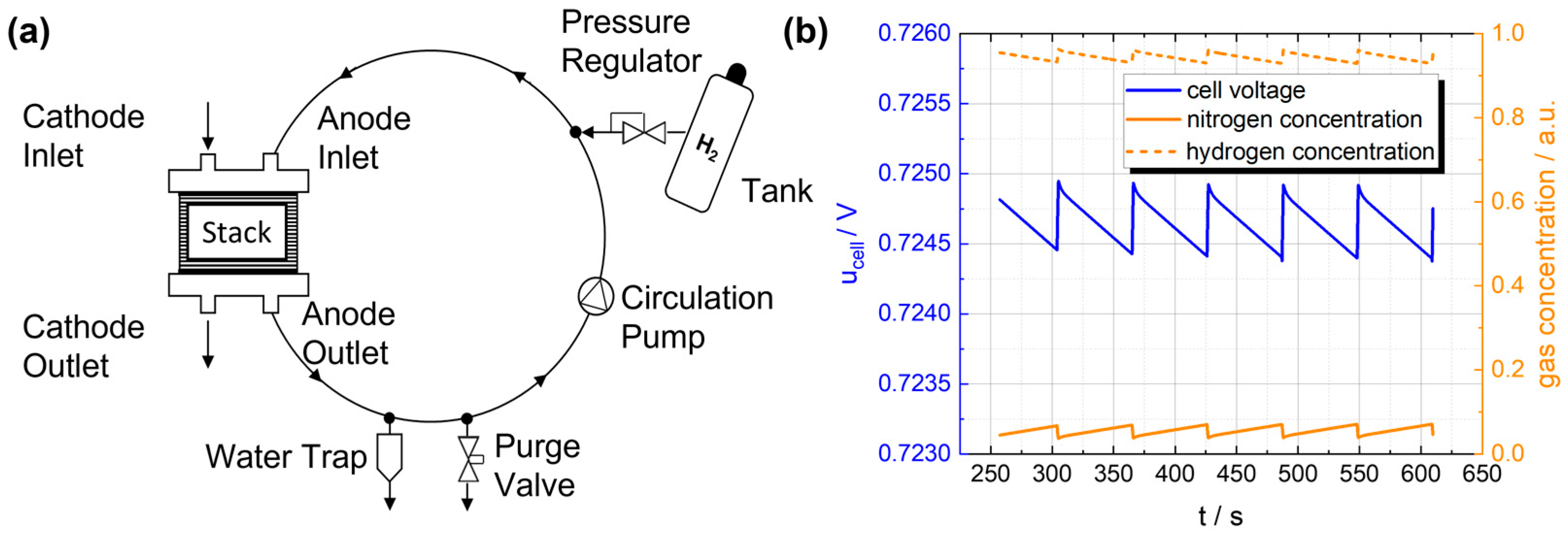
Figure 1. (a) Simplified illustration of the recirculating gas mixture within the anode circulation system, connected to the tank and purge valve. (b) Development of hydrogen and nitrogen concentrations in a fuel cell stack and the resulting stack voltage [9].
Energies 17 05158 g001
Figure 2. (a) Model of a sensor prototype. Ti/Pd thin-film structures are used as the sensor element. Contact pads made of Au are required for the electrical connection to the circuit board. (a.1) Schematic representation of the working principle, according to which the H atoms diffuse into the metal lattice of the palladium, where they reduce the electrical conductivity of the Pd due to electron scattering. (b) Device layer stack with an organic active material and a structured bottom electrode to generate several (here, six) sensors on one chip. (b.1) Schematic drawing of the hyperfine interaction. The precision of the spins around the hyperfine field is altered with the application of an external magnetic field (if Bext > Bhyp). Hence, the precision of the spins aligns with the external magnetic field, leading to a change in the current of the device.
Energies 17 05158 g002
Figure 3. Side view of the H2 test chamber and the integration of the (1) palladium-based sensor, (2) the reference sensor BME680 (Bosch) and (3) the organic-based sensor (based on organic TADF materials) with light emission at a wavelength of ~440 nm. The gas is introduced into the gas chamber during the measurement.
Energies 17 05158 g003
Figure 4. Demonstration of the working principle of both sensor types. (a) H2-Gas response for the organic material-based sensor, where 4-vol-% H2 was injected at the times marked by the vertical black dashed lines, leading to a significant decrease in the current through the device, in the case when the measurements were performed under an applied magnetic field. (b) Time course of the electrical resistance as a function of the hydrogen concentration. The hydrogen concentration was changed by 5 vol-% every 150 s, starting at 100 vol-%.
Energies 17 05158 g004
Figure 5. (a) CAD model of the experimental fuel cell platform Open-Source-Stack (OSS). (b) Detailed CAD model of the customized end plate with an example sensor and corresponding fastening elements.
Energies 17 05158 g005
Figure 6. (a) CAD model of an anode bipolar plate of the experimental fuel cell platform Open-Source-Stack (OSS). (b) CAD model of an anode bipolar plate of the OSS with highlighted perspective sensor integration areas.
Energies 17 05158 g006
Figure 7. (a) Simplified illustration of the recirculating gas mixture within the anode circulation system with integrated hydrogen sensors. (b) Comparison of fuel cell system efficiency between standard purge processes at a specific voltage drop and a model predictive control (MPC) approach with hydrogen measurements for different operating points [9].
Energies 17 05158 g007
Disclaimer/Publisher’s Note: The statements, opinions and data contained in all publications are solely those of the individual author(s) and contributor(s) and not of MDPI and/or the editor(s). MDPI and/or the editor(s) disclaim responsibility for any injury to people or property resulting from any ideas, methods, instructions or products referred to in the content.