Abstract
In this paper, to achieve versatile, cost-effective charging for dual-motor EVs, a multi-functional integrated onboard charger is constructed using a dual-motor driving system. In the driving mode, a five-phase flux-switching permanent-magnet (FSPM) motor powers the front, while a three-phase FSPM motor drives the rear. While in the charging mode, different topologies are adopted for different application scenarios, such as the single-phase AC charging mode, the three-phase AC charging mode, and the DC charging mode. The five-phase FSPM motor and its inverters serve as a boost-based AC/DC converter in both single-phase and three-phase AC charging modes, transforming grid power to DC. In the DC charging mode, they are reconfigured to function as a buck converter. During the three-phase AC charging mode, the three-phase FSPM motor and its inverters take on the role of a rear-stage buck converter. They function to regulate the rectified DC voltage, ensuring it meets battery charging needs. The performance of the integrated charger is validated through simulation and experiment results.
1. Introduction
Driven by the global consensus on reducing carbon emissions, the electric vehicle (EV) industry is experiencing explosive growth, supported by policy incentives, technological advancements, and increased market penetration [1]. As EV technology rapidly evolves, basic functionalities are no longer sufficient for consumers. Instead, exceptional performance and reliability are more appealing. Consequently, an increasing number of EV models now incorporate dual-motor traction systems to deliver enhanced power output, improved efficiency, and optimized control. Examples of this trend include the Tesla Model 3 Performance, Li L9, BYD Don, along with premium products from numerous other brands.
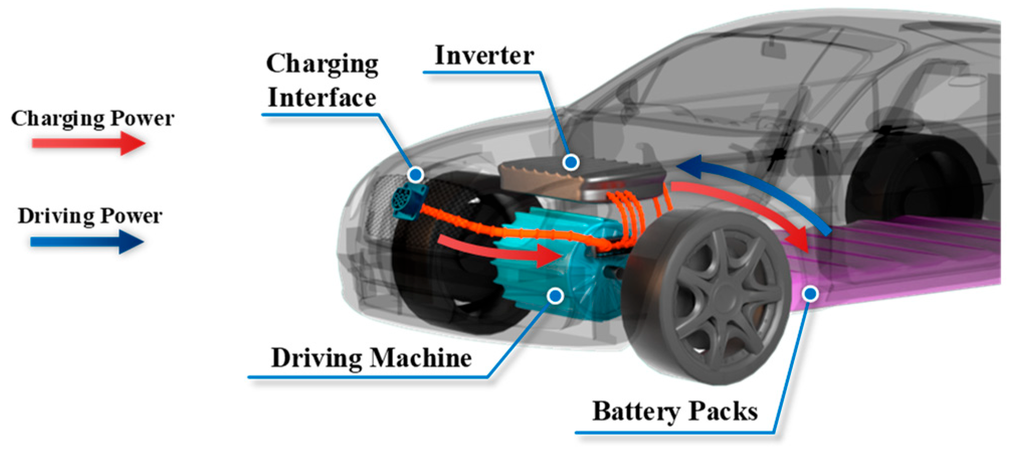
However, it is noteworthy that range anxiety continues to occupy the foremost concern for prospective EV buyers [2,3]. Given that a significant advancement in battery technology remains elusive in the immediate future, the pursuit of a convenient and affordable charging solution retains paramount importance in the ongoing growth of the EV industry. Therefore, as illustrated in Figure 1, an emerging design for an integrated motor-driving and onboard battery-charging system has gained increasing prominence. In this approach, the motor windings along with the inverters within the driving system are reconfigured to obtain charging function. The cutting-edge technologies in this area have been extensively reviewed in several papers [4,5,6]. Additionally, the power capacity of the EV driving system, such as its motor and power devices, generally exceeds that of a conventional battery charger, which eliminates the requirement for additional power components when adapting the system for charging purposes. Moreover, this approach also leads to notable reductions in overall size, weight, and cost, further enhancing its cost efficiency. Hence, the integrated onboard charging system has shown considerable competitive advantages in the market.

Figure 1.
Integrated onboard motor-driving and battery-charging system.
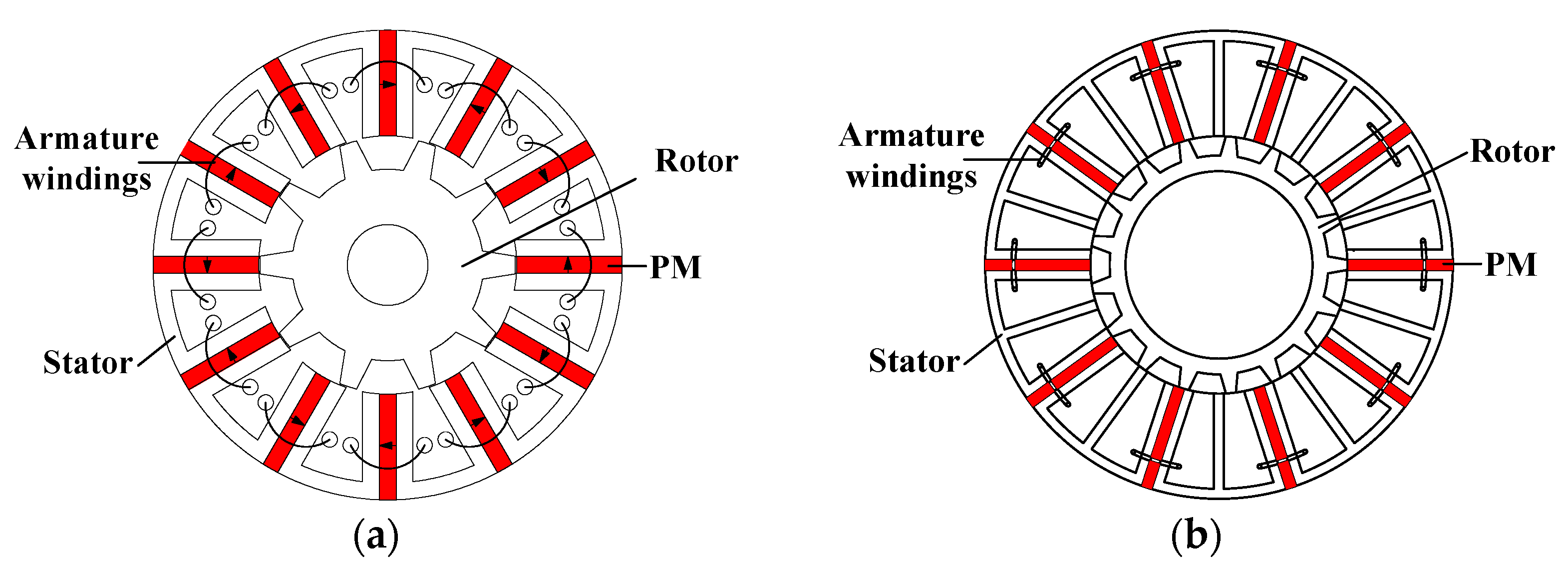
Following extensive research, a variety of integrated charging systems leveraging distinct motor types have been introduced. These include the utilization of multi-phase motors [7], switched reluctance motors (SRMs) [8], and flux-switching permanent magnet (FSPM) motors [9]. Furthermore, the integrated onboard chargers designed for dual-motor systems [10] and four-wheel drive EVs [11] have been developed, though they are limited to single-phase charging capability. Meanwhile, findings from studies [9,12] indicate that multi-phase motors can effectively resolve the issue of starting torque during the charging process. In addition, a two-stage architecture demonstrates the potential to facilitate efficient voltage alignment between the grid and the battery. Thus, to implement a practical and economical method that supports both single-phase and three-phase AC charging as well as DC charging function for dual-motor EVs, a two-stage integrated charging system has been proposed. This system utilizes a five-phase FSPM motor in conjunction with a three-phase FSPM motor. The configurations of these motors are illustrated in Figure 2.

Figure 2.
Topologies of the employed motors. (a) The three-phase FSPM motor; (b) the five-phase FSPM motor.
The paper is organized as follows. In Section 2, the system topology, configuration methods, and operating principles of different charging modes are presented in detail. In Section 3, the control strategy is introduced, along with the simulation results for the charging mode. In Section 4, the experimental validation of each operating mode is presented. Finally, the conclusion is drawn in Section 5. Notably, the core concept of this work was initially given at the 2022 IEEE Transportation Electrification Conference and Expo, Asia-Pacific (ITEC Asia-Pacific) [13]. In this extended version, we have expanded upon the content related to the DC charging function, added further simulation results, and provided a comprehensive set of experimental findings. Furthermore, the writing style and structure of the paper have been improved substantially.
2. Topology and Operation Principle Analysis
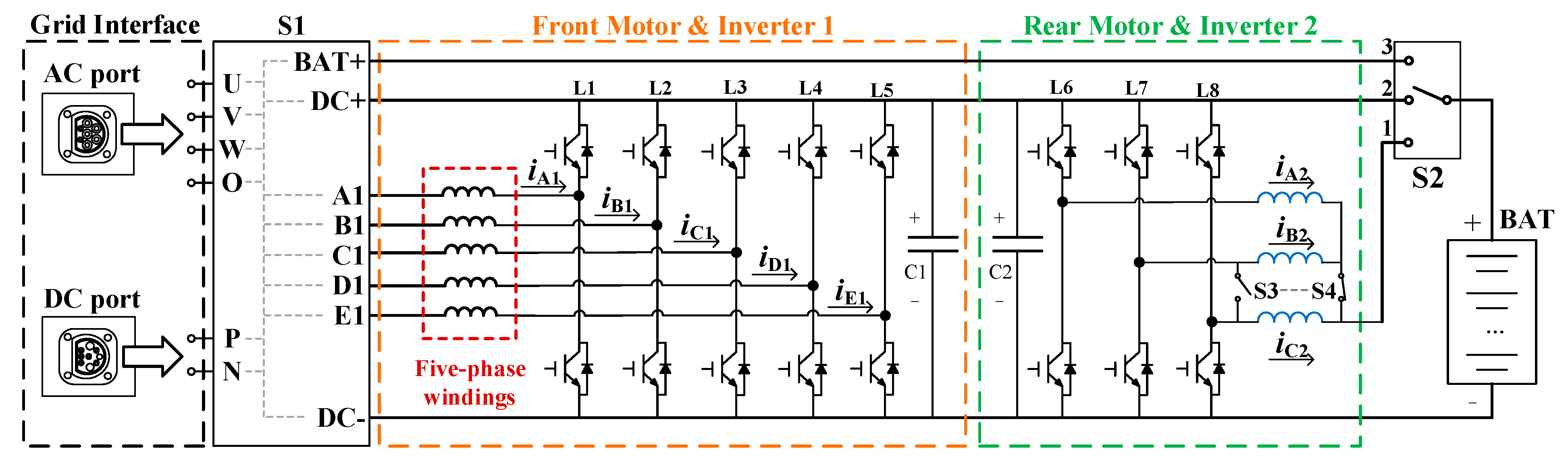
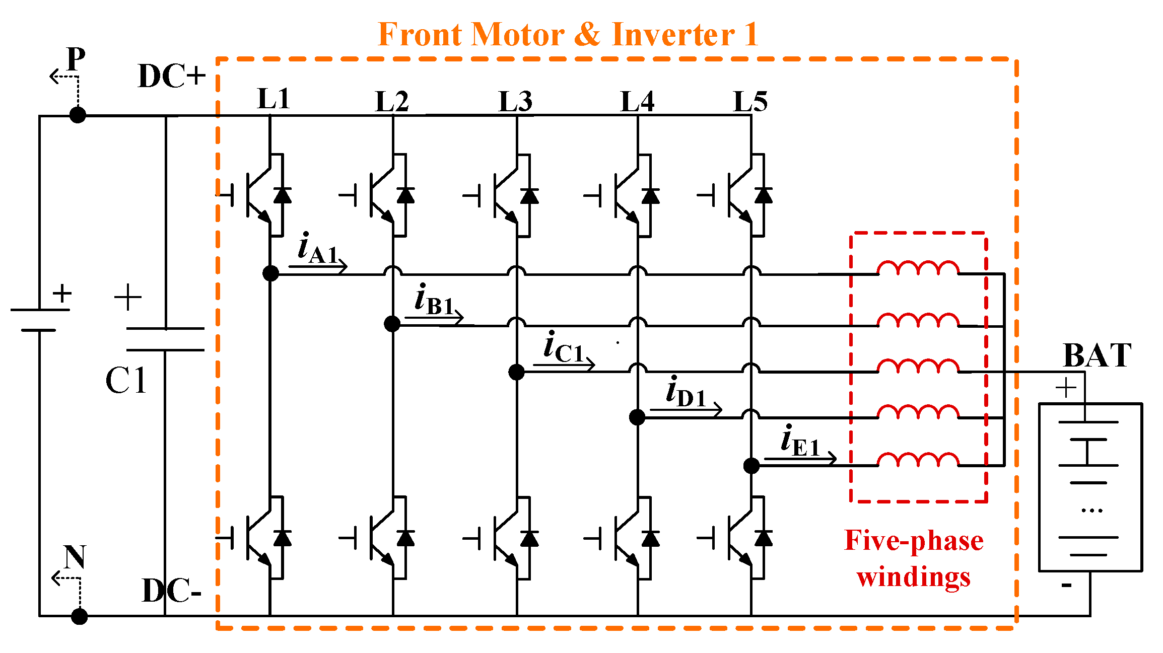
The system topology of the proposed integrated charger is shown in Figure 3 and consists of five main components: the grid interface (with AC and DC charging ports), the front motor and inverter 1 (representing a conventional five-phase motor-driving system), the rear motor and inverter 2 (constituting a typical three-phase motor-driving system), the mode-switching device (comprising S1, S2, S3, and S4), and the battery pack. As outlined in Section 1, the proposed integrated charger supports four operational modes: driving mode, single-phase and three-phase AC charging mode, and DC charging mode. In this system, the three-phase AC charging mode offers two variant topologies to accommodate varying charging requirements.
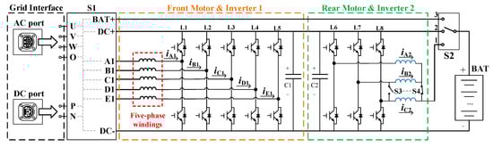
Figure 3.
System topology of the proposed integrated battery charger.
2.1. The Driving Mode
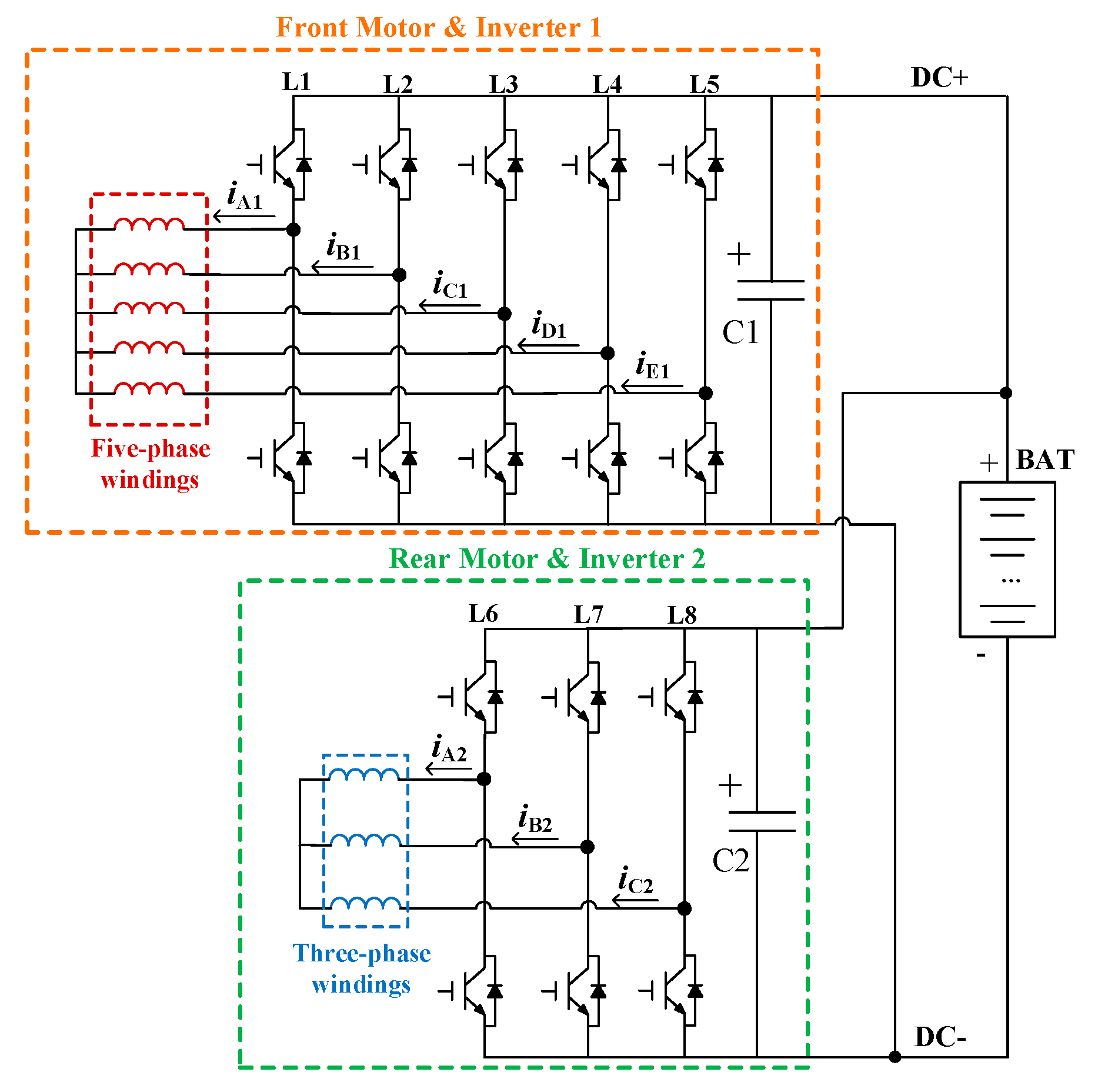
When S1 connects the windings of the front motor using a five-phase star-connection method, with S2 set to position 2, S3 turned off, and S4 activated, the system transitions into driving mode. The equivalent circuit for this mode is shown in Figure 4. At this point, the inverter legs L1 to L5 are responsible for driving the five-phase motor, while L6 to L8 similarly drive the three-phase motor. Both traction systems share the DC bus, which is directly connected to the battery pack.
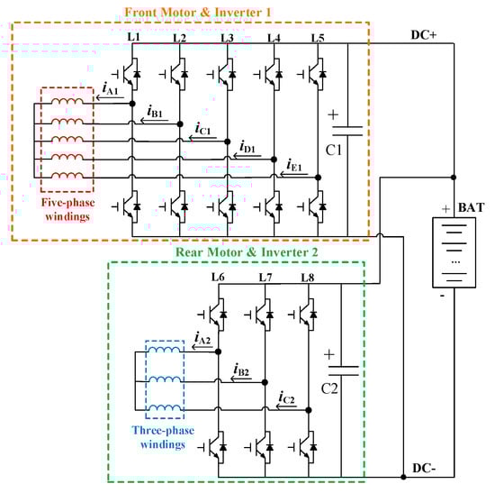
Figure 4.
Equivalent circuit of the driving mode.
2.2. The Single-Phase AC Charging Mode
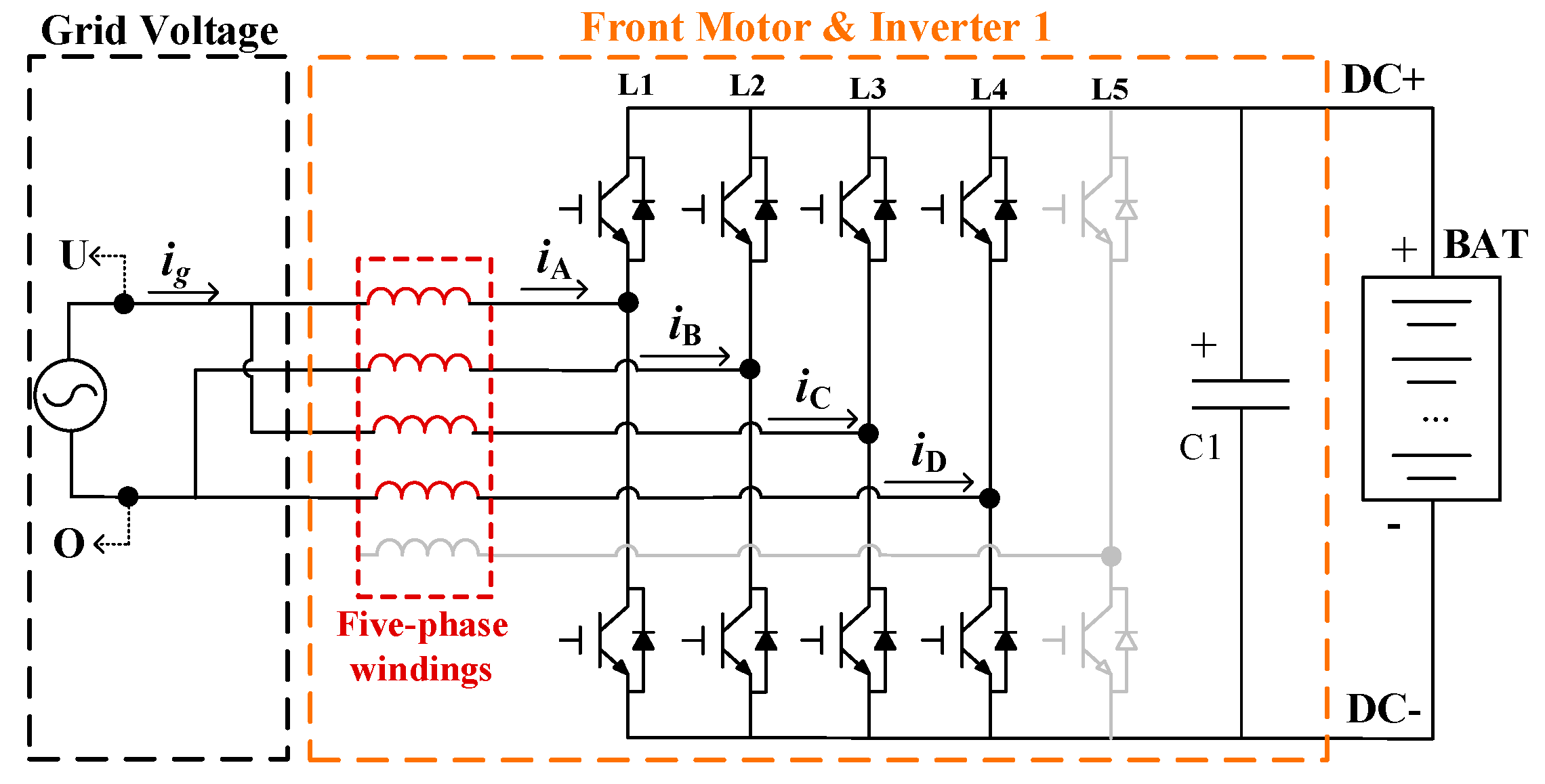
Assuming an RMS value of the grid phase voltage at 110 V/50 Hz and a rated battery voltage of 288 V, the single-phase AC charging function can be achieved using a single-stage boost rectifier. Thus, the system’s single-phase AC charging mode can be implemented exclusively using the front motor and its inverter. When S1 connects the single-phase AC grid to the five-phase motor windings via the U-port and O-port, with S2 in position 2, the system transitions into single-phase AC charging mode. The equivalent circuit for this mode is shown in Figure 5. Here, the five-phase FSPM motor and its inverter operate as a single-phase boost AC–DC converter, utilizing the windings of phase A, B, C, and D. This reconfigured circuit efficiently converts the single-phase grid AC voltage into DC to meet the battery charging requirements. Notably, the winding selection is inspired by [12], aimed at optimizing power output, minimizing pulsating torque, and eliminating starting torque.
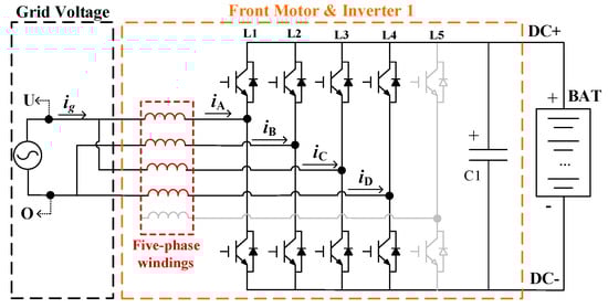
Figure 5.
Equivalent circuit of the single-phase AC charging mode.
2.3. The Three-Phase AC Charging Mode
For a boost-based three-phase rectifier, the DC output voltage Udc must satisfy the following [14]:
where UL,pk is the peak line-to-line voltage of the input three-phase supply. In this paper, with the RMS value of the grid phase voltage set at 110 V/50 Hz, the converted DC voltage theoretically cannot fall below 311 V. This level exceeds the required battery voltage, indicating that a single-stage topology is insufficient for the three-phase AC charging mode, and a buck process must be included.
Udc ≥ 1.15UL,pk,
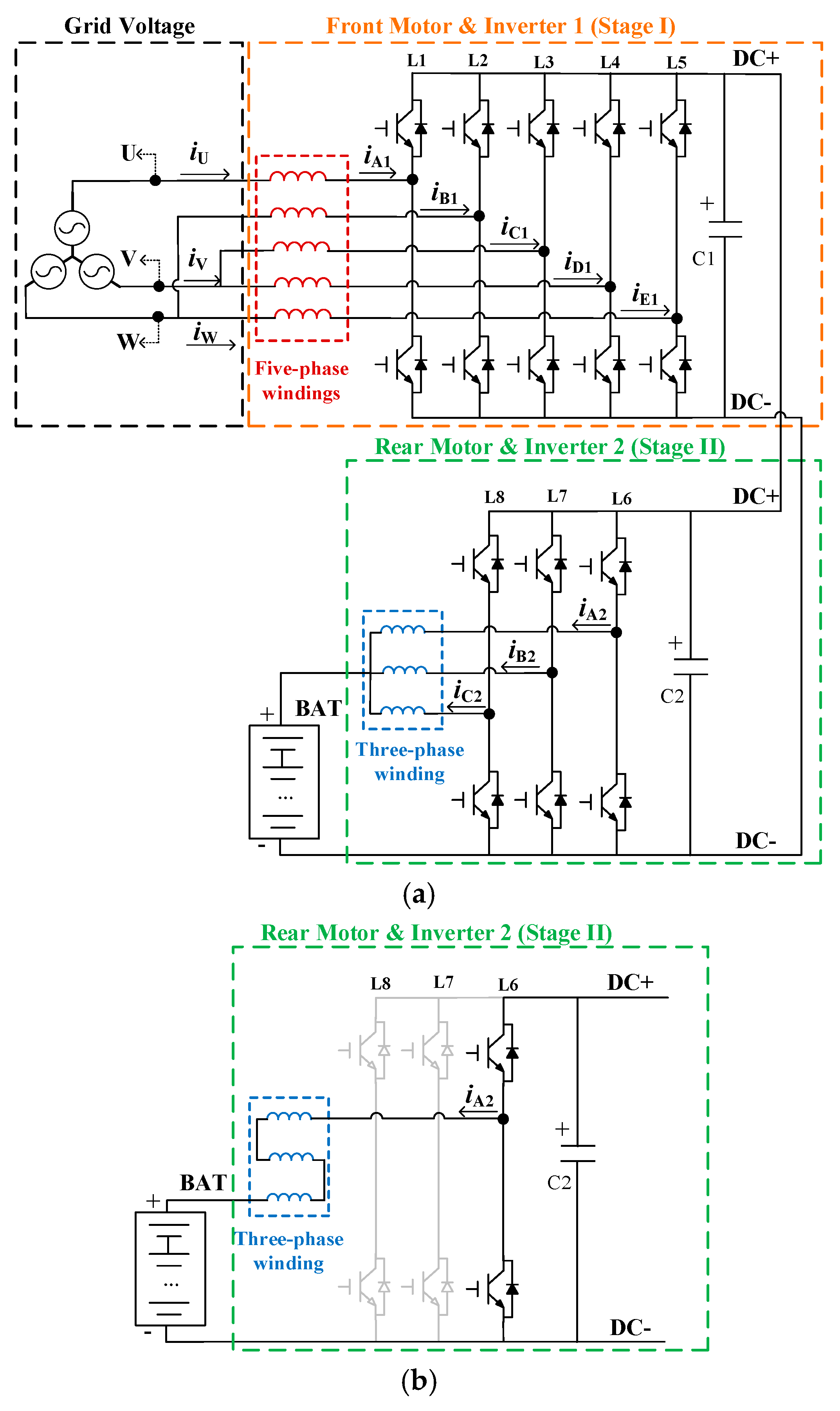
Thus, the proposed system employs a two-stage charging setup in three-phase charging mode. In this configuration, S1 connects the three-phase AC grid to the five-phase motor windings via the U, V, and O ports, with S2 set to position 1. The equivalent circuit is shown in Figure 6. In Stage I, the five-phase motor along with its inverters operate as a three-phase full-bridge rectifier with a boosting function. The winding selection for Stage I, as outlined in [9], also eliminates starting torque during the charging process. Simultaneously, Stage II uses the three-phase motor and its inverter as a buck converter. It is crucial for achieving the necessary voltage matching in the integrated charger.
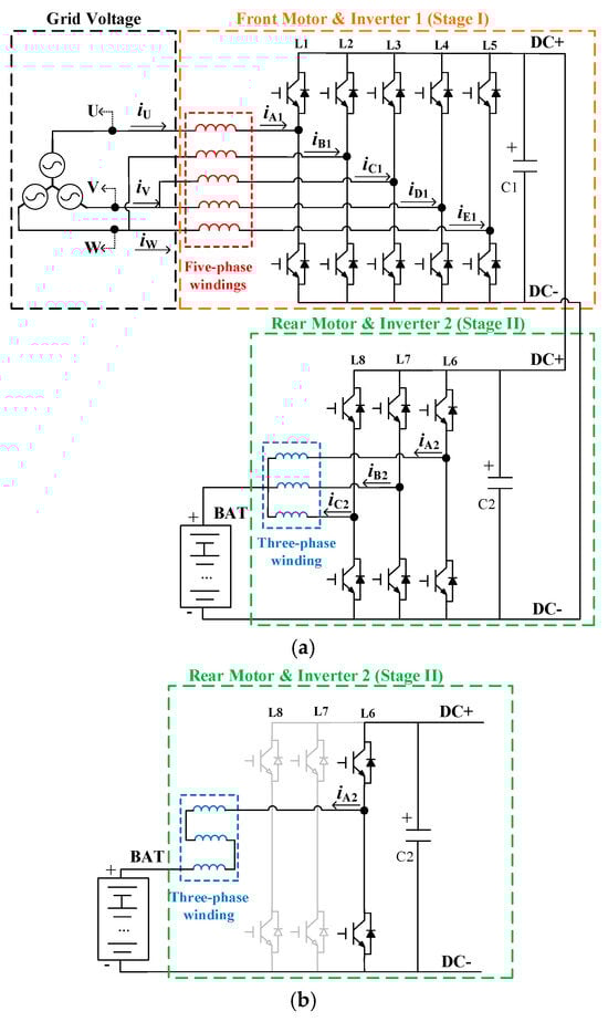
Figure 6.
Equivalent circuit of the three-phase AC charging mode. (a) High-power mode. (b) Low-ripple mode.
The system can be further configured into two distinct sub-modes using S3 and S4: the high-power mode (S3 off, S4 on; see Figure 6a) and the low-ripple mode (S3 on, S4 off; see Figure 6b). In the high-power mode, the paralleled windings act as the output inductor, suitable for high-power charging but potentially increasing current ripple due to reduced inductance. In contrast, the windings are connected in series in the low-ripple mode, boosting inductance and minimizing ripple in the charging current.
2.4. The DC Charging Mode
With the rapid advancement of EV driving range, high-voltage DC fast charging has become an essential feature in modern EVs. The proposed integrated charger can be configured to serve as a high-power DC charger as well. Assuming a DC input voltage of 360 V from the grid and a rated battery voltage of 288 V, a high-power buck converter is required for the charging process. When S1 connects the input voltage to the DC bus via the P and N ports, and simultaneously links the battery’s positive terminal to the neutral point of the five-phase motor windings via the BAT+ port, with S2 set to position 3, the system is switched into DC charging mode. The equivalent circuit for this mode is presented in Figure 7. Here, the five-phase motor and its inverter are reconfigured to function as a buck converter, with the paralleled windings enabling the charging current to reach up to five times the rated current of the motor.
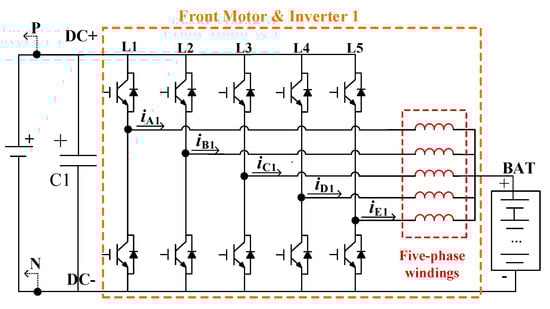
Figure 7.
Equivalent circuit of the DC charging mode.
In this section, we present a detailed overview of the system topology and operational principles for the proposed integrated charger across various modes. We also provide an in-depth analysis of these modes. The proposed system supports a wide range of charging methods, including single-phase AC charging (slow charge), three-phase AC charging (with two sub-modes for different application scenarios), and DC charging (fast charge). In the subsequent sections, the control methods for each mode, along with verification through both simulation and experimental results, will be given.
3. Control Method and Simulation Validation
Considering the well-established control strategies for both three-phase and five-phase motor drive systems, and given that the primary focus of this paper is the development of a multi-functional integrated onboard charging system by reconfiguring the driving system, we will not cover the control method for the driving mode. Instead, this section is dedicated solely to discussing the control method for the charging mode.
3.1. Control Method of the AC Charging Mode
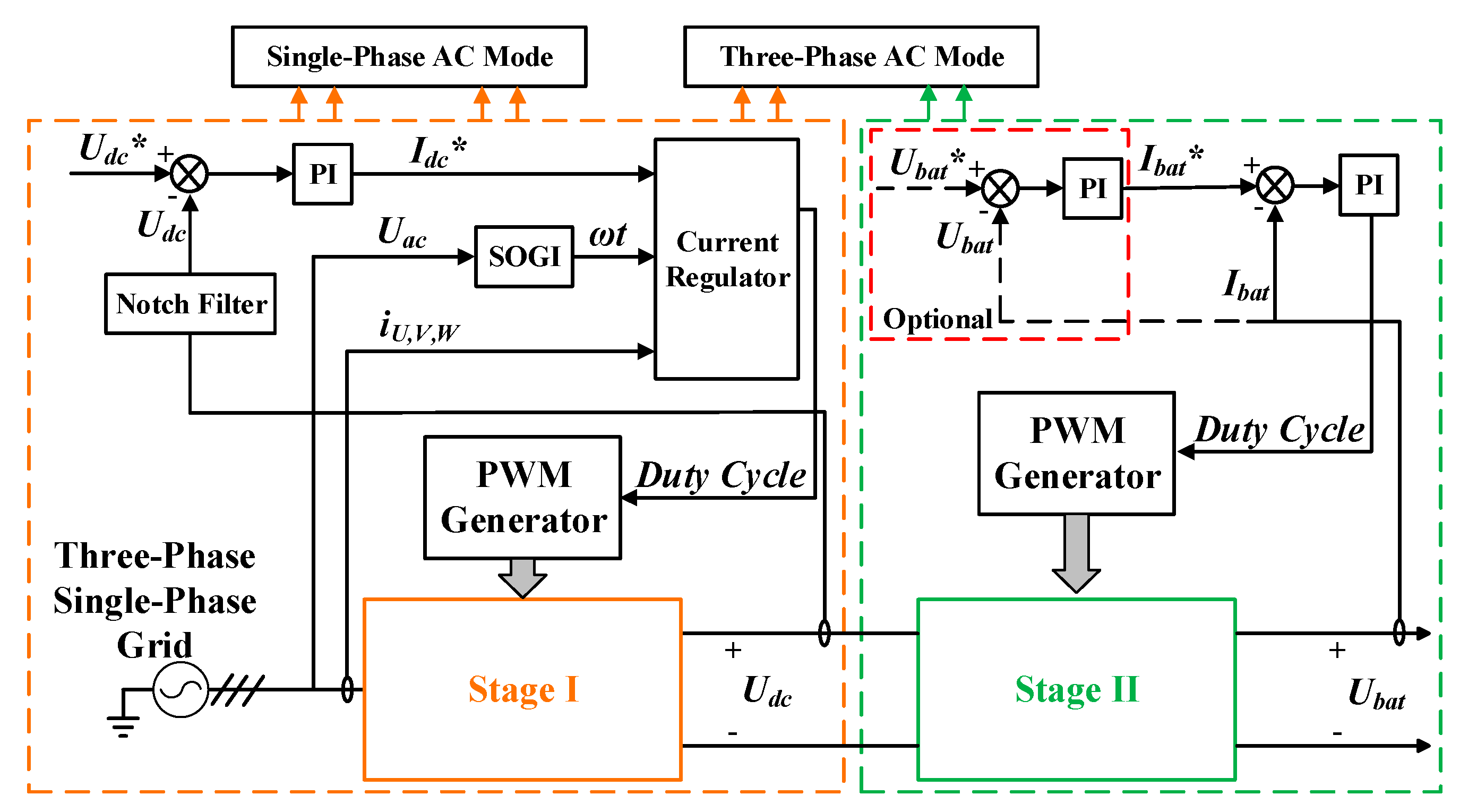
The control diagram for the AC charging mode is shown in Figure 8. As mentioned in Section 2, the five-phase motor and its inverter are used as the power stage for both the single-phase AC charging mode and Stage I of the three-phase AC charging mode. This allows them to share certain control strategies. Stage I adopts a dual closed-loop structure consisting of an outer voltage loop and an inner current loop. Since the rectifier can induce fluctuations in the DC bus voltage at twice the fundamental frequency, leading to ripple in the proportional–integral (PI) controller of the voltage loop, a notch filter (NF) is added to filter out specific noise frequencies in Udc. For the current loop in Stage I, previously reported current balance control methods for five-phase motors, as noted in [9,15], are also applicable here. In Stage II, the same dual-loop control method is used. Notably, the voltage loop in Stage II of the proposed system is not always necessary.
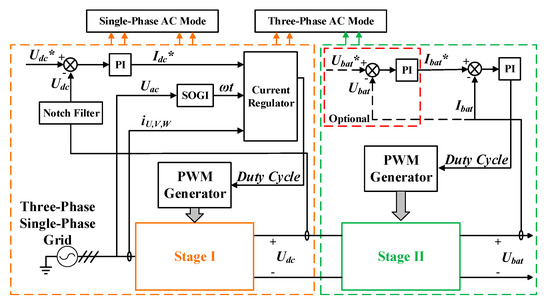
Figure 8.
The control diagram of the AC charging mode.
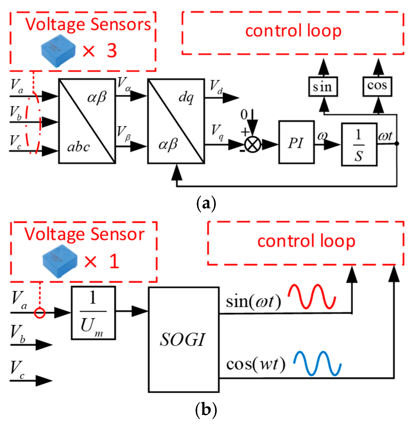
To perform power factor correction (PFC), the system must acquire the grid voltage phase. Figure 9a shows the standard process for a three-phase phase-locked loop (PLL), which requires three voltage sensors. However, there is only one voltage sensor in the origin driving system. Inspired by [9], a second-order generalized integrator (SOGI) is employed to obtain the grid voltage phase without additional devices. The process for achieving PFC operation using SOGI is illustrated in Figure 9b. SOGI also filters grid voltage noise and reduces harmonics in the sampled signal, as illustrated in Figure 10.
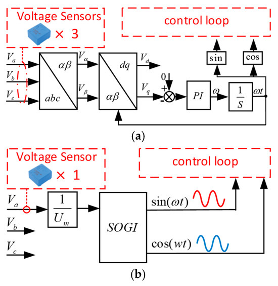
Figure 9.
Grid phase sampling method. (a) PLL. (b) SOGI.
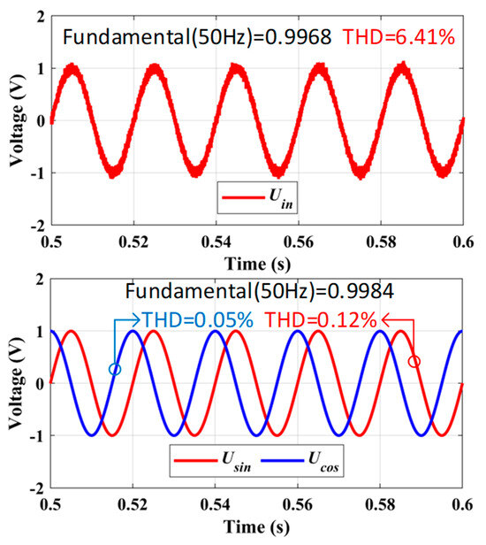
Figure 10.
Simulation results of SOGI.
3.2. Control Method of the DC Charging Mode
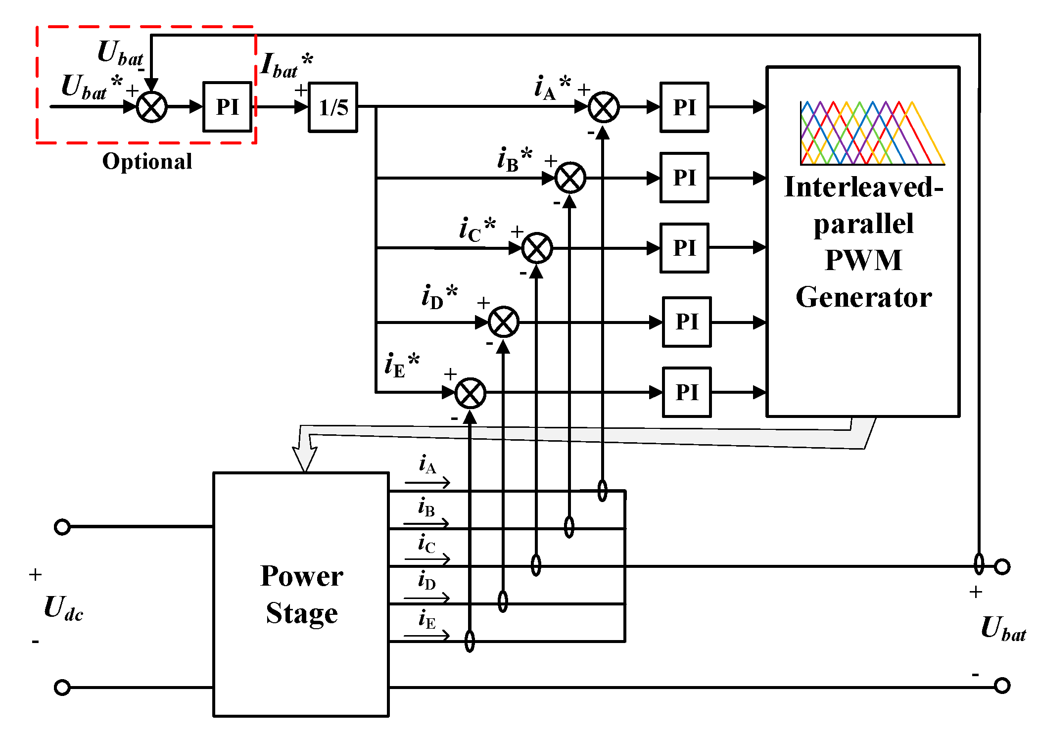
The control diagram for the DC charging mode is shown in Figure 11. As with the AC charging mode, both the inner current loop and the outer voltage loop are employed in this mode. In the inner current loop, a reference current is set for each phase, equal to 1/5 of the desired battery current (Ibat*). To minimize charging current ripple, an interleaved–parallel PWM method is used.
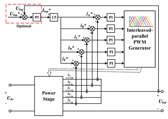
Figure 11.
The control diagram of the DC charging mode.
3.3. Simulation Verification
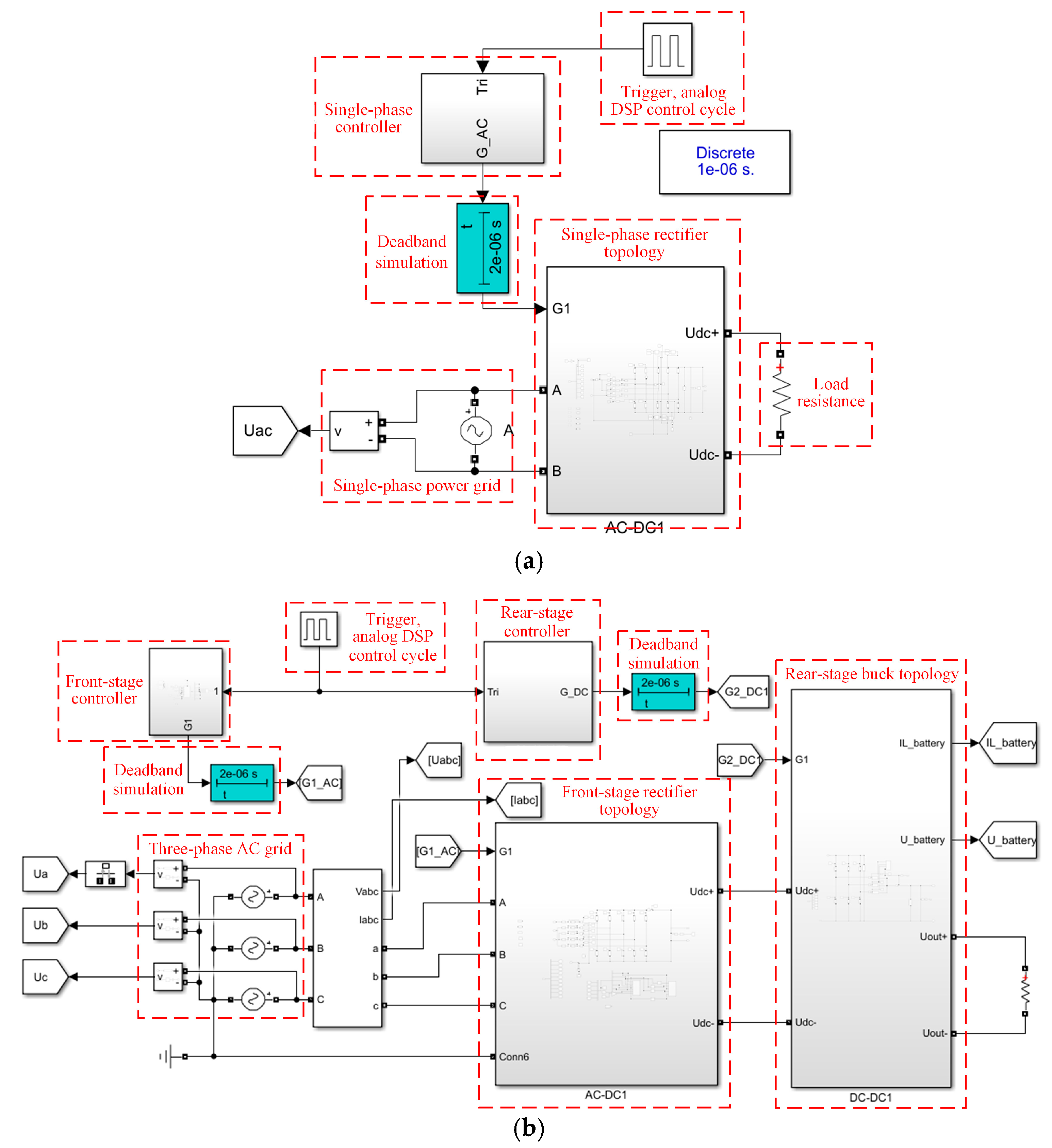
To verify the effectiveness of the presented integrated charger, based on the topologies given in Section 2 and the control methods discussed above, a system simulation model is built based on MATLAB/Simulink (R2024a). Figure 12 illustrates the simulation models for both single-phase and three-phase AC charging modes. The main simulation parameters are listed in Table 1.
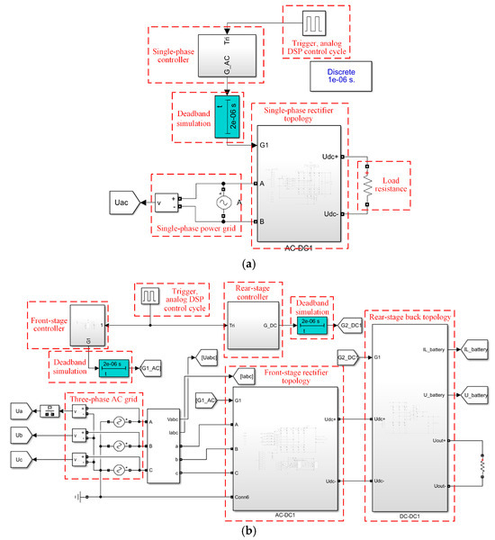
Figure 12.
Simulation models based on MATLAB/Simulink. (a) Single-phase AC charging model. (b) Three-phase AC charging model.

Table 1.
Simulation parameters.
Based on the simulation parameters listed above, the results for the system in three operating modes are shown in Figure 13, Figure 14 and Figure 15.
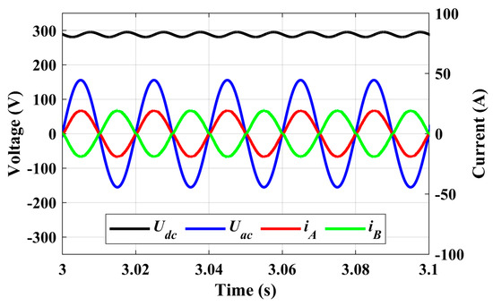
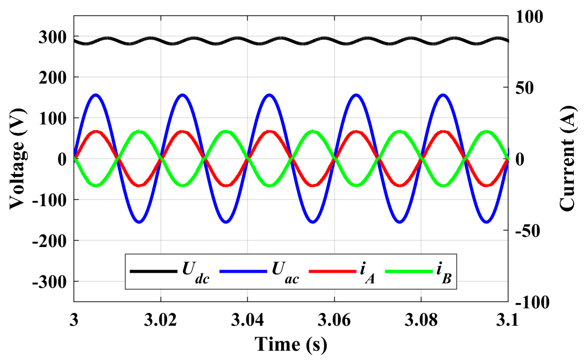
Figure 13.
Simulation results in the single-phase AC charging mode.
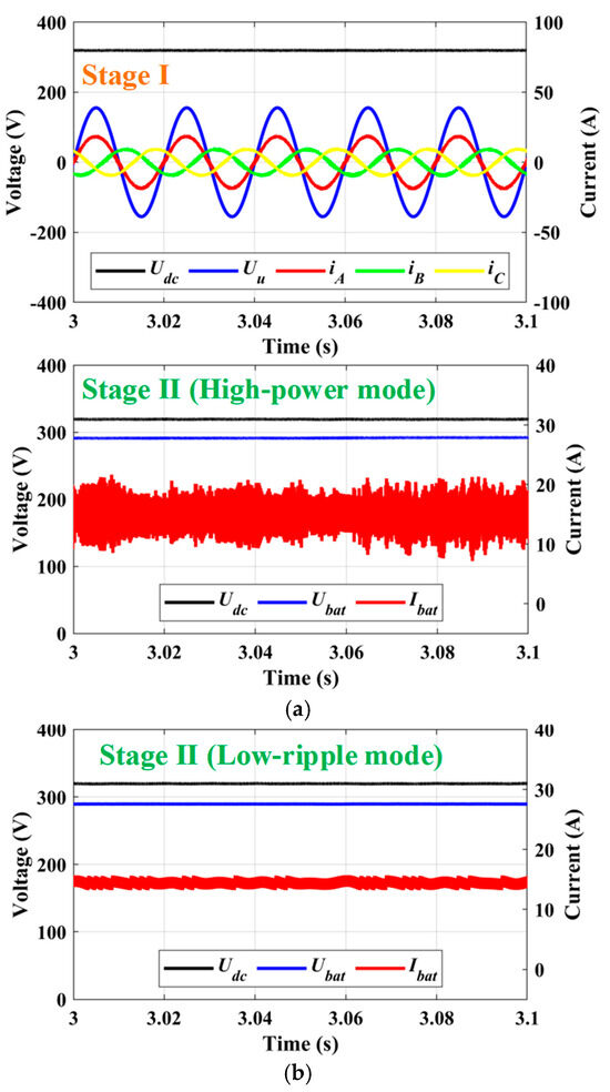
Figure 14.
Simulation results of the three-phase AC charging mode. (a) High-power mode. (b) Small-ripple mode.
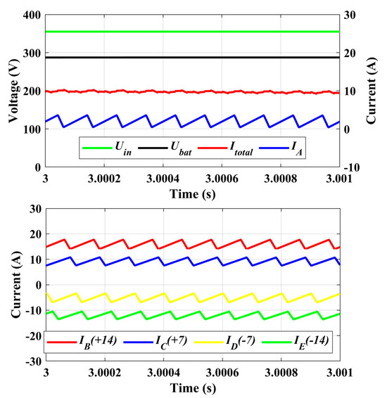
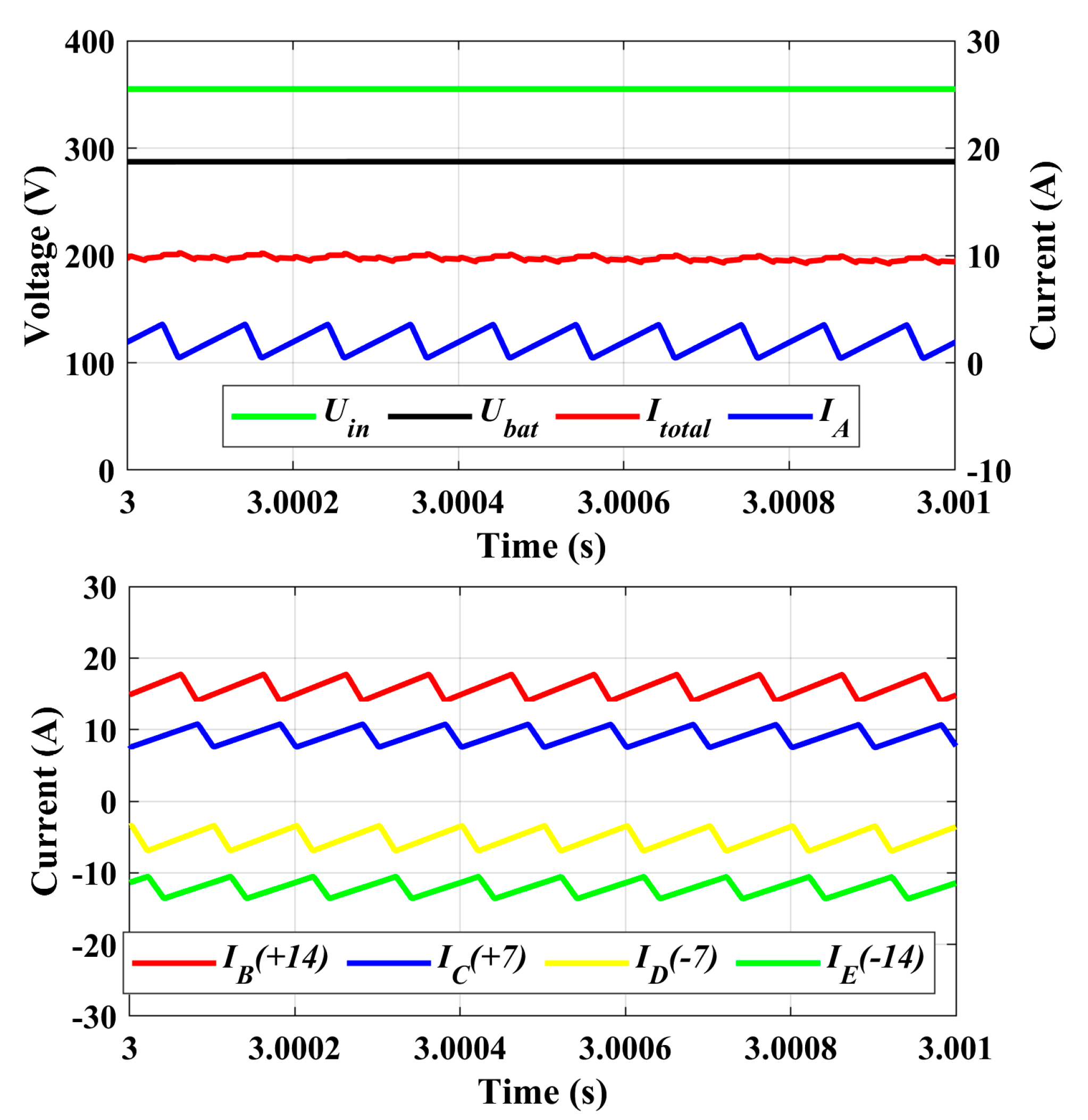
Figure 15.
Simulation results of the DC charging mode.
Figure 13 shows the charging performance of the single-phase AC charging mode. It clearly illustrates that the single-phase AC grid voltage Uac is converted into DC, with the DC bus voltage Udc stably regulated at 288 V to charge the battery. Additionally, the phase current iA is in phase with Uac, indicating that the system operates with PFC.
Figure 14 presents the simulation results for the three-phase AC charging mode. The upper half of Figure 14a shows the outcomes for Stage I, demonstrating the conversion of the three-phase AC grid voltage UU (with UV and UW omitted for clarity) into DC. The DC bus voltage Udc is effectively regulated at 320 V. As previously discussed, there are two sub-modes within Stage II of the three-phase AC charging mode. The lower half of Figure 14a and Figure 14b illustrate Stage II in different sub-modes, respectively. It is evident that both modes effectively buck the Udc from 320 V to the specified battery charging voltage Ubat, which is set at 288 V. However, due to differences in output inductance, the low-ripple mode provides significant advantages in reducing charging current ripple.
Figure 15 displays the simulation results of the DC charging mode. In the upper part of Figure 15, the buck converter effectively transforms the input DC voltage Uin from 360 V to the charging voltage Ubat at 288 V. Moreover, the lower part of Figure 15 illustrates the effectiveness of employing an interleaved PWM scheme, where the phase currents are offset by 2π/5 radians. This approach significantly reduces charging current ripple and meets the charging requirements.
The simulation results clearly indicate that the proposed integrated onboard charger successfully completes the charging functions in single-phase AC, three-phase AC, and DC charging modes within the simulation environment.
4. Experiment Validation
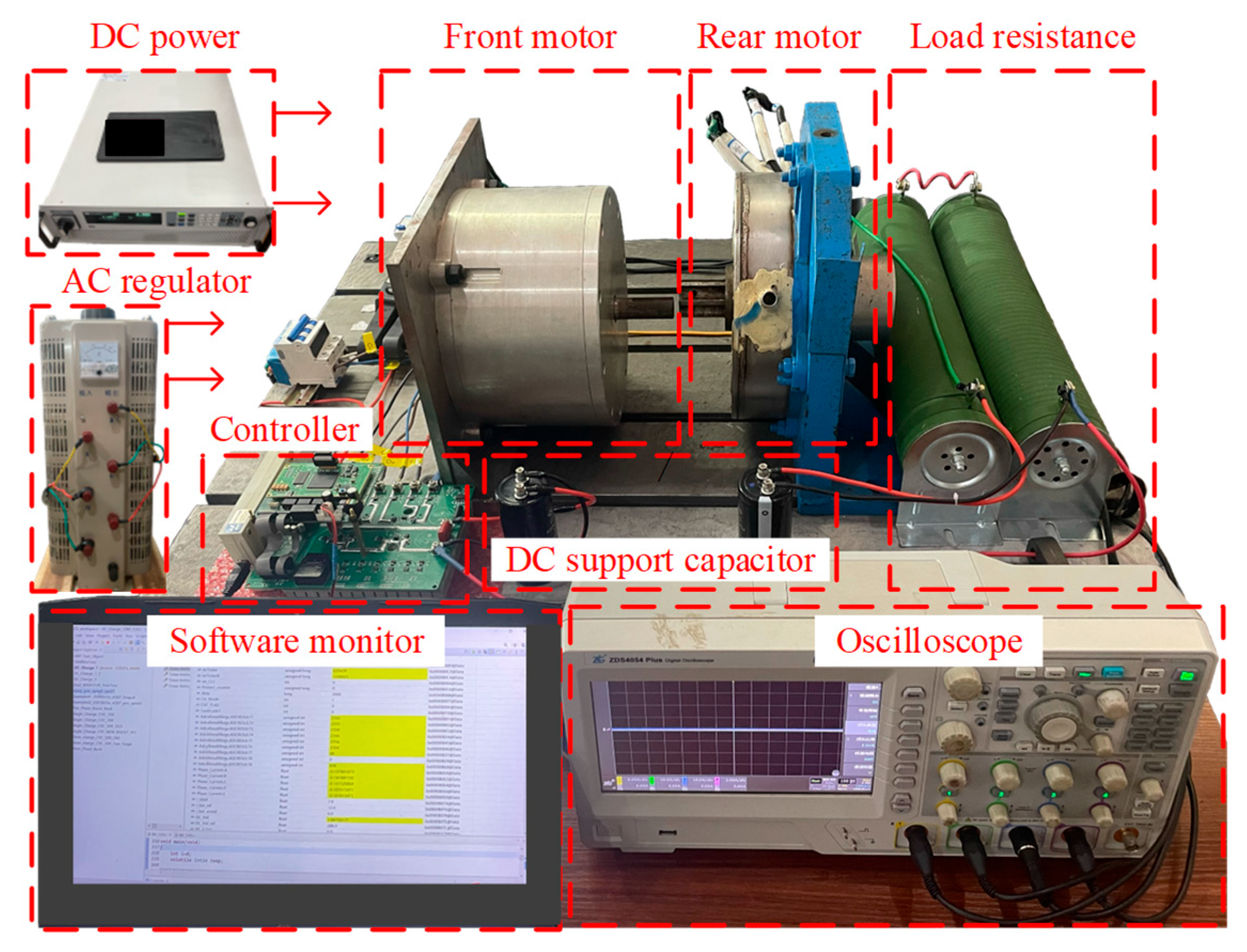
To validate the effectiveness of the proposed integrated charger in all modes, an experimental platform based on a dual-motor system has been established, as shown in Figure 16. This system encompasses several key components, including the front motor (a five-phase FSPM motor), the rear motor (a three-phase FSPM motor), the controller (based on TMS320F28377D, Texas Instruments, Dallas, TX, USA), the computer monitor (AOC), a four-channel oscilloscope (ZLG ZDS4054 Plus, Guangzhou, China), power sources (comprising an AC power regulator (TSGC2-9kva, CHNT, Shanghai, China) and a DC power regulator (IT6018C-500-120, ITECH, Nanjing, China)), and an adjustable load resistor (RX20, Kunshan Shengju An Electronic Technology Co., Ltd., Suzhou, China). The DC and AC power regulators supply the necessary input power, while the load resistor simulates the behavior of a battery pack. The operational parameters listed in Table 1 are also applied during experimental testing.
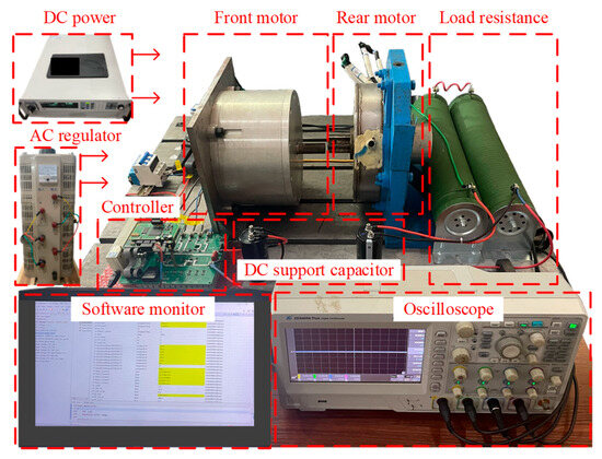
Figure 16.
The experimental platform based on a dual-motor system.
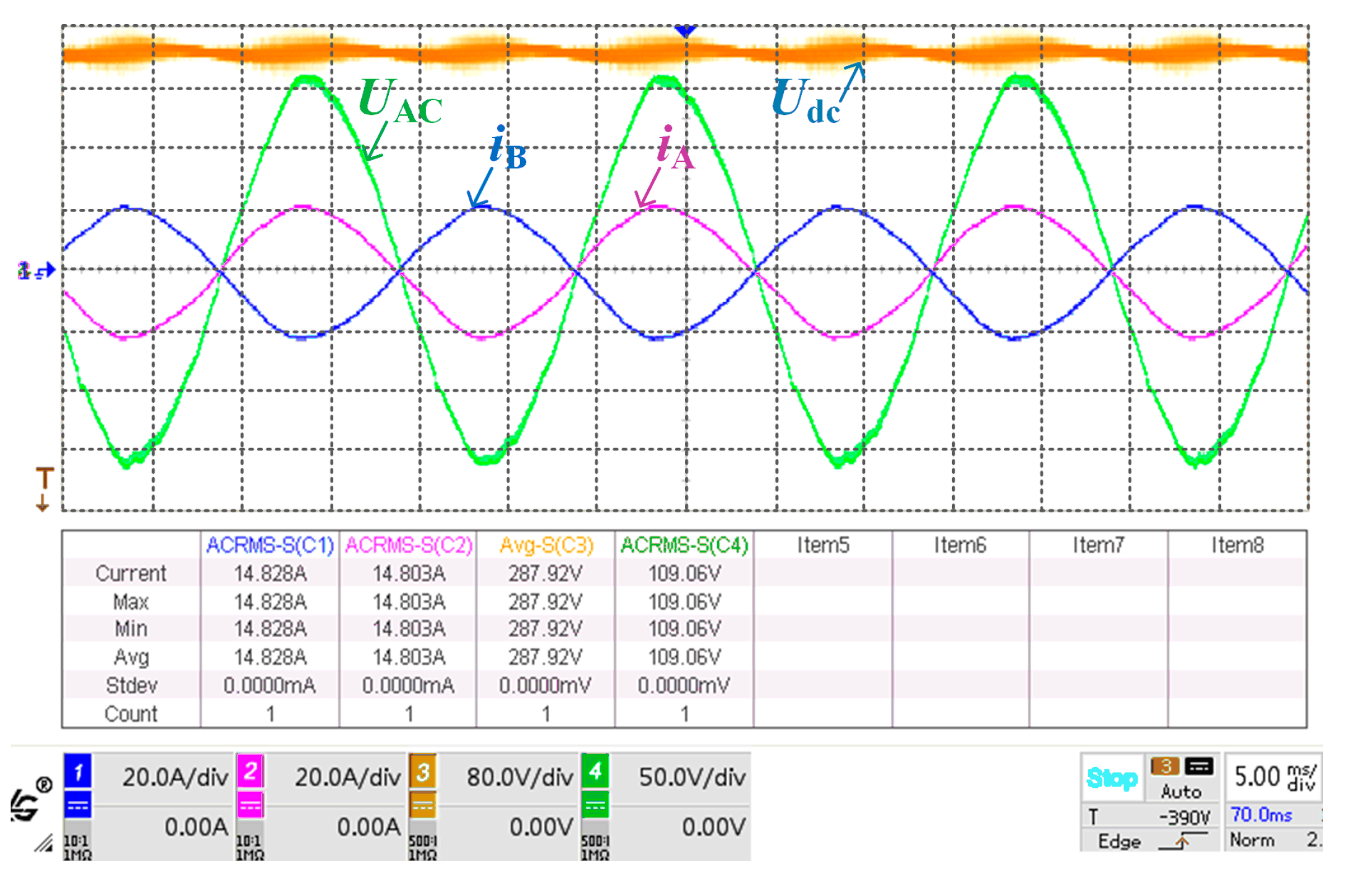
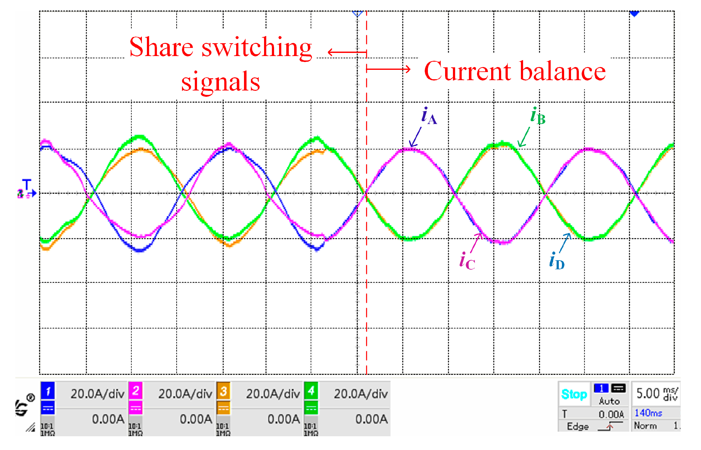
Using this experimental platform, several tests have been performed. Figure 17 presents the experimental results of the single-phase AC charging mode. It can be seen that the converter boosts the AC input voltage Uac from 110 V/50 Hz to the DC bus voltage Udc at 288 V. Meanwhile, iA and UAC are in phase, confirming the successful operation of the PFC module. Notably, a current balancing algorithm was applied in this mode due to the unequal inductance of different windings. Figure 18 compares the experimental phase current waveforms before and after the application of the algorithm, demonstrating its effectiveness.
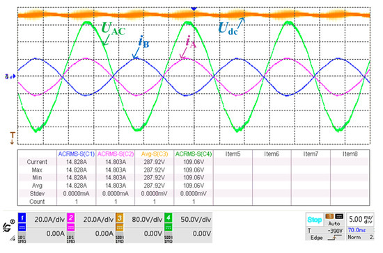
Figure 17.
Experiment results of the single-phase AC charging mode.
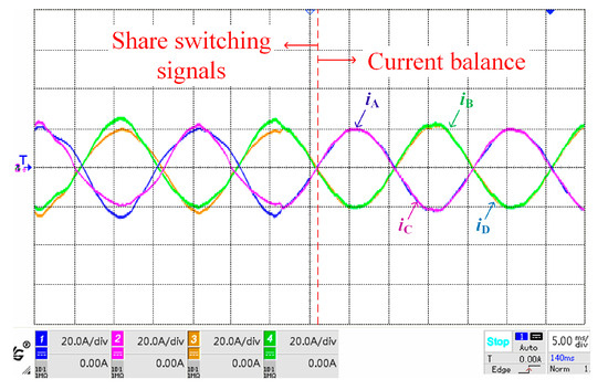
Figure 18.
Experiment results of the current balancing algorithm.
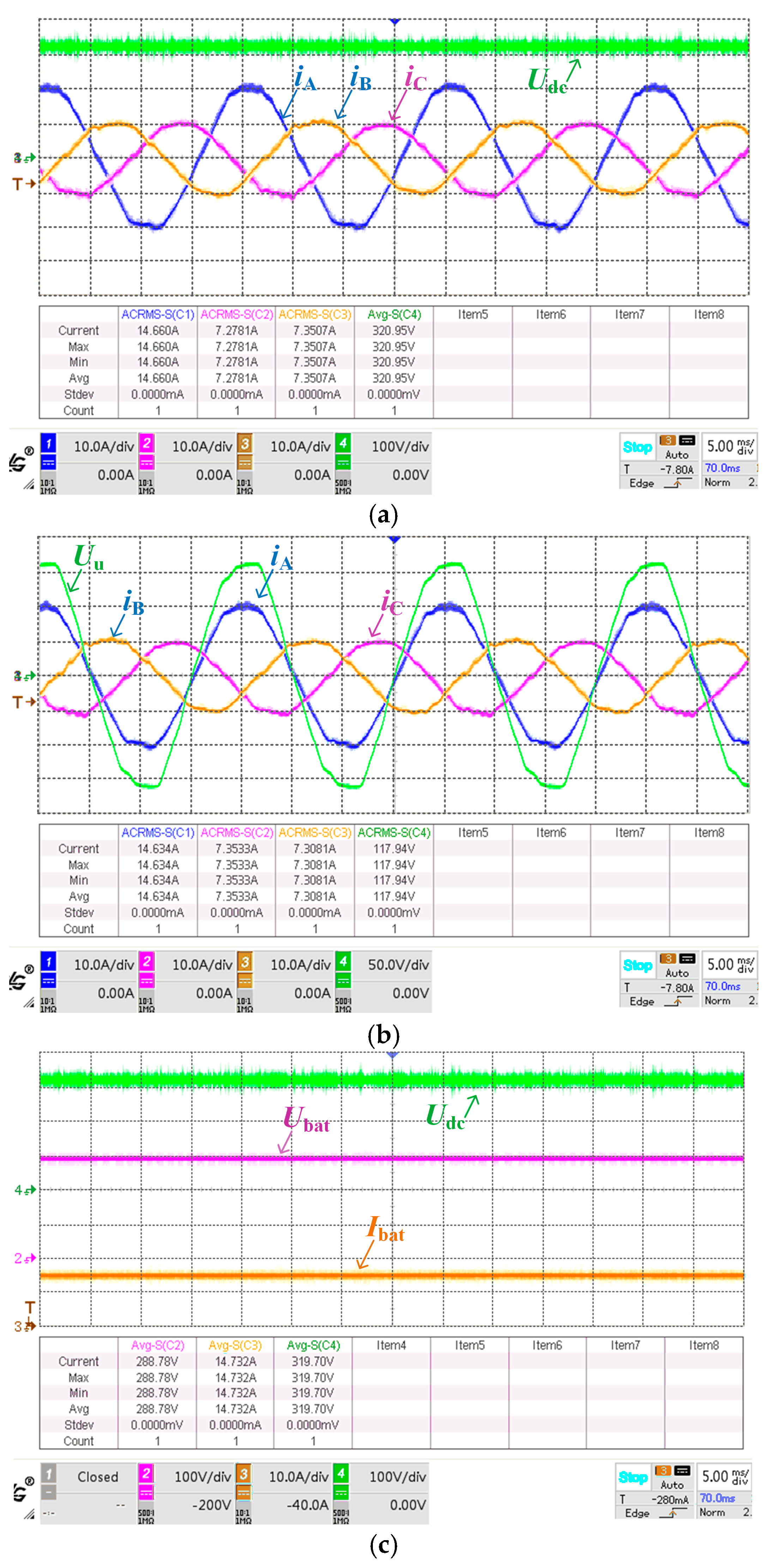
Additionally, Figure 19 presents the experimental results for the three-phase AC charging mode. Due to the limitations of our laboratory equipment (a four-channel oscilloscope), the results of Stage I are shown separately in Figure 19a and Figure 19b, while the results of Stage II are displayed in Figure 19c. Figure 19a illustrates the system’s ability to convert three-phase AC power into DC, with the DC bus voltage Udc effectively regulated at 320 V. All phase currents exhibit correct phase and amplitude. Figure 19b shows the phase relationship between iA and UU, confirming the successful operation of the PFC module in the three-phase charging mode. In Figure 19c, the waveforms for Stage II depict the reduction of Udc from 320 V to Ubat at 288 V, with the charging current Ibat being stable and well-controlled. Importantly, this experiment was conducted in the low-ripple sub-mode for enhanced performance.
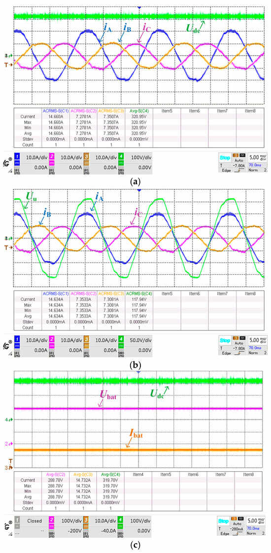
Figure 19.
Experiment results of the three-phase AC charging mode. (a) Experiment results of Stage I: part I. (b) Experiment results of Stage I: part II. (c) Experiment results of Stage II.
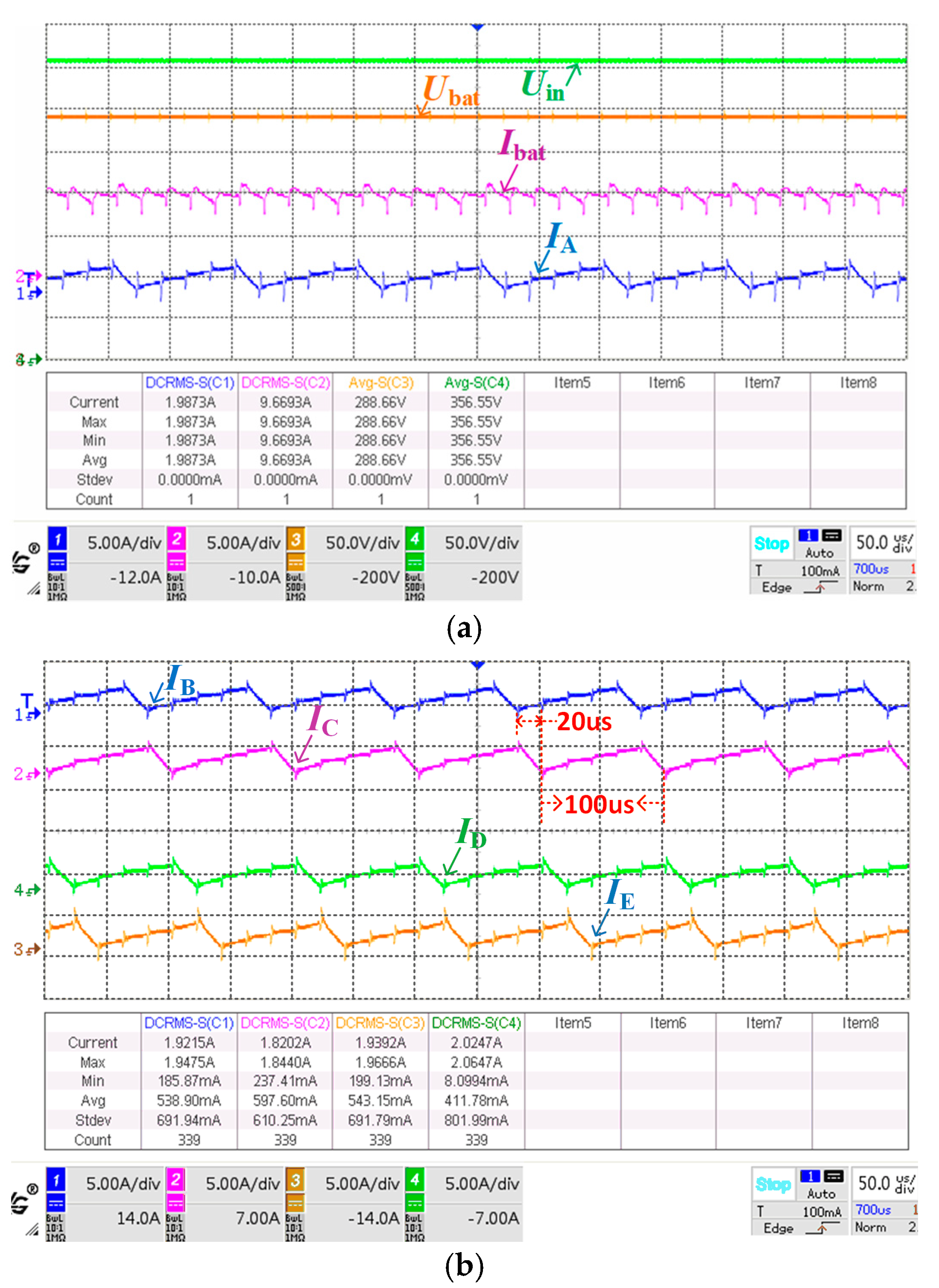
Finally, the experimental results for the DC charging mode are given in Figure 20. Figure 20a presents the input voltage Uin, output voltage Ubat, output current Ibat, and phase-A current IA, while Figure 20b displays the currents of the other phases. These results demonstrate a strong correlation between the experimental and simulation outcomes for the DC charging mode.
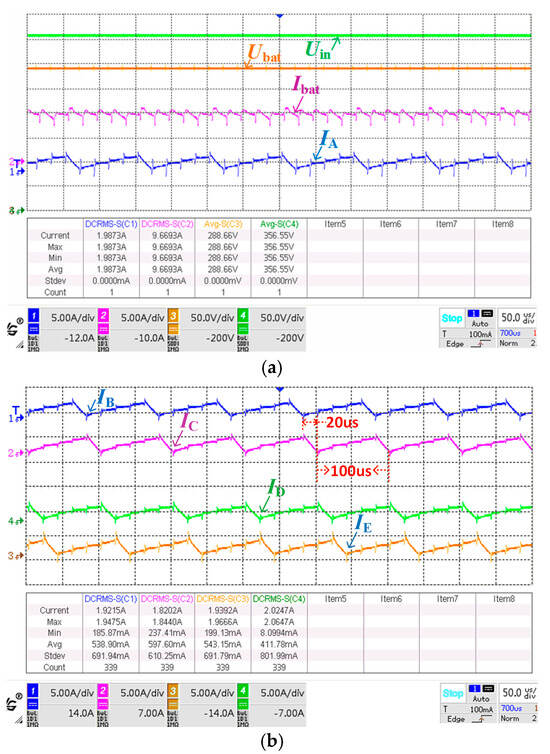
Figure 20.
Experiment results of the DC charging mode. (a) Experiment results: part I. (b) Experiment results: part II.
Based on the measured data, the charging efficiency of the proposed system is summarized in Table 2. A comparison with several existing integrated charging systems is also provided, highlighting the performance metrics of the proposed system. Note that the motor utilized in our experiment was initially optimized with a focus solely on traction performance. Consequently, the efficiency observed during the charging process may be lower compared to some of the reference systems. In future work, we aim to further optimize the motor by simultaneously considering both charging and traction performance.
Table 2.
Comparison of the operating efficiency between the proposed system and existing systems.
Based on the aforementioned simulation and experimental results, Table 3 summarizes the comparison of results obtained from the MATLAB/Simulink model and physical experiments under various operating modes. It can be seen that all parameters align very well, verifying the validity of the constructed model.
Table 3.
Comparison of results from MATLAB/Simulink model and physical experiments.
5. Conclusions
In this paper, a multi-functional integrated onboard battery charger for EVs is developed based on a dual-motor driving system. The system topology and operational principles are analyzed, and the control method is introduced. Both simulation and experimental results are provided to verify the effectiveness of the system, along with its operational efficiency. The key conclusions are summarized as follows:
- Based on a dual-motor traction system, the proposed integrated charger can operate in driving mode, single-phase AC charging mode, three-phase AC charging mode, and DC charging mode;
- In different working modes, different topologies are required. The mode-switching method will be a great obstacle for the application of this type of integrated onboard charger;
- The efficiency of the AC charging mode is not high enough. In order to reach the best performance, the two motors should be redesigned.
Author Contributions
Conceptualization, M.T.; methodology, M.T. and X.L.; software, X.L.; validation, M.T., X.L., Y.C. and Z.X.; writing—original draft preparation, X.L.; writing—review and editing, Y.C. and M.T.; supervision, L.S.; funding acquisition, M.T. All authors have read and agreed to the published version of the manuscript.
Funding
This research was funded by the National Natural Science Foundation of China (NSFC), grant number 52307059, and the Natural Science Foundation of Jiangsu Province, grant number BK20210347.
Data Availability Statement
Data are contained within the article.
Conflicts of Interest
The authors declare no conflicts of interest.
References
- Zhuo, Z.; Du, E.; Zhang, N.; Nielsen, C.P.; Lu, X.; Xiao, J.; Wu, J.; Kang, C. Cost Increase in the Electricity Supply to Achieve Carbon Neutrality in China. Nat. Commun. 2022, 13, 3172. [Google Scholar] [CrossRef] [PubMed]
- Cheng, M.; Tong, M. Development Status and Trend of Electric Vehicles in China. Chin. J. Electr. Eng. 2017, 3, 1–13. [Google Scholar]
- Yilmaz, M.; Krein, P.T. Review of Battery Charger Topologies, Charging Power Levels, and Infrastructure for Plug-In Electric and Hybrid Vehicles. IEEE Trans. Power Electron. 2013, 28, 2151–2169. [Google Scholar] [CrossRef]
- Metwly, M.Y.; Abdel-Majeed, M.S.; Abdel-Khalik, A.S.; Hamdy, R.A.; Hamad, M.S.; Ahmed, S. A Review of Integrated On-Board EV Battery Chargers: Advanced Topologies, Recent Developments and Optimal Selection of FSCW Slot/Pole Combination. IEEE Access 2020, 8, 85216–85242. [Google Scholar] [CrossRef]
- Singh, A.K.; Pathak, M.K. A Comprehensive Review of Integrated Charger for On-Board Battery Charging Applications of Electric Vehicles. In Proceedings of the 2018 IEEE 8th Power India International Conference (PIICON), Kurukshetra, India, 10–12 December 2018; pp. 1–6. [Google Scholar]
- Na, T.; Yuan, X.; Tang, J.; Zhang, Q. A Review of On-Board Integrated Charger for Electric Vehicles and A New Solution. In Proceedings of the 2019 IEEE 10th International Symposium on Power Electronics for Distributed Generation Systems (PEDG), Xi’an, China, 3–6 June 2019; pp. 693–699. [Google Scholar]
- Subotic, I.; Bodo, N.; Levi, E. Single-Phase On-Board Integrated Battery Chargers for EVs Based on Multiphase Machines. IEEE Trans. Power Electron. 2016, 31, 6511–6523. [Google Scholar] [CrossRef]
- Yu, Z.; Gan, C.; Ni, K.; Chen, Y.; Qu, R. Dual-Electric-Port Bidirectional Flux-Modulated Switched Reluctance Machine Drive With Multiple Charging Functions for Electric Vehicle Applications. IEEE Trans. Power Electron. 2021, 36, 5818–5831. [Google Scholar] [CrossRef]
- Tong, M.; Cheng, M.; Wang, S.; Hua, W. An On-Board Two-Stage Integrated Fast Battery Charger for EVs Based on a Five-Phase Hybrid-Excitation Flux-Switching Machine. IEEE Trans. Ind. Electron. 2021, 68, 1780–1790. [Google Scholar] [CrossRef]
- Tang, L.; Su, G.-J. A Low-Cost, Digitally-Controlled Charger for Plug-in Hybrid Electric Vehicles. In Proceedings of the 2009 IEEE Energy Conversion Congress and Exposition, San Jose, CA, USA, 20–24 September 2009; pp. 3923–3929. [Google Scholar]
- Lee, S.J.; Sul, S.K. An Integral Battery Charger for 4 Wheel Drive Electric Vehicle. In Proceedings of the 1994 IEEE Industry Applications Society Annual Meeting, Denver, CO, USA, 2–6 October 1994; Volume 1, pp. 448–452. [Google Scholar]
- Tong, M.; Cheng, M.; Hua, W.; Ding, S. A Single-Phase On-Board Two-Stage Integrated Battery Charger for EVs Based on a Five-Phase Hybrid-Excitation Flux-Switching Machine. IEEE Trans. Veh. Technol. 2020, 69, 3793–3804. [Google Scholar] [CrossRef]
- Tong, M.; Liu, X.; Sun, L.; Xu, Z.; Cheng, M.; Zou, Q. Investigation of An Integrated Battery Charger for EVs Based on A Dual-Motor Traction System. In Proceedings of the 2022 IEEE Transportation Electrification Conference and Expo, Asia-Pacific (ITEC Asia-Pacific), Haining, China, 28–31 October 2022; pp. 1–5. [Google Scholar]
- Erickson, R.W.; Maksimović, D. Pulse-Width Modulated Rectifiers. In Fundamentals of Power Electronics; Erickson, R.W., Maksimović, D., Eds.; Springer International Publishing: Cham, Switzerland, 2020; pp. 917–923. [Google Scholar]
- Shi, C.; Tang, Y.; Khaligh, A. A Three-Phase Integrated Onboard Charger for Plug-In Electric Vehicles. IEEE Trans. Power Electron. 2018, 33, 4716–4725. [Google Scholar] [CrossRef]
- Lacroix, S.; Laboure, E.; Hilairet, M. An Integrated Fast Battery Charger for Electric Vehicle. In Proceedings of the 2010 IEEE Vehicle Power and Propulsion Conference, Lille, France, 1–3 September 2010; pp. 1–6. [Google Scholar]
- Haghbin, S.; Khan, K.; Zhao, S.; Alakula, M.; Lundmark, S.; Carlson, O. An Integrated 20-kW Motor Drive and Isolated Battery Charger for Plug-In Vehicles. IEEE Trans. Power Electron. 2013, 28, 4013–4029. [Google Scholar] [CrossRef]
- Wang, Z.; Liu, B.; Guan, L.; Zhang, Y.; Cheng, M.; Zhang, B.; Xu, L. A Dual-Channel Magnetically Integrated EV Chargers Based on Double-Stator-Winding Permanent-Magnet Synchronous Machines. IEEE Trans. Ind. Appl. 2019, 55, 1941–1953. [Google Scholar] [CrossRef]


Disclaimer/Publisher’s Note: The statements, opinions and data contained in all publications are solely those of the individual author(s) and contributor(s) and not of MDPI and/or the editor(s). MDPI and/or the editor(s) disclaim responsibility for any injury to people or property resulting from any ideas, methods, instructions or products referred to in the content. |
© 2024 by the authors. Licensee MDPI, Basel, Switzerland. This article is an open access article distributed under the terms and conditions of the Creative Commons Attribution (CC BY) license (https://creativecommons.org/licenses/by/4.0/).