Abstract
This paper is aimed at proposing a calculation model for the ground resistance of a grounding scheme servicing a high-voltage direct-current converter station. The method is based on the equivalence of current conduction and electric field from the grounding scheme through the surrounding medium. The grounding scheme is composed of three concentric ring electrodes supported by two horizontal conductors and eight vertical rods. The calculated ground resistance is against the experimental value of with an error of . The calculated ground resistance value agrees reasonably well with that of as obtained using CYMGRD software (version 7.0). The calculated surface-potential values over the ground surface agreed reasonably well with those measured experimentally, with an average deviation not exceeding . This study is designed to investigate how ground resistance is decreased by the increase in the scheme parameters, including the rods’ diameter and length, as well as the radius of the inner and outer rings. The dependency of the ground resistance on the soil type is also investigated.
1. Introduction
Due to the intensive use of electrical energy, power transmission over long distances has become necessary in recent years. With the growth in interconnection projects, high-voltage direct current (HVDC) has become suitable as it has several advantages. Among these advantages are greater power transfer per conductor, simpler line construction as each conductor can be operated as an independent circuit, no charging current, no skin effect, lesser corona power loss and radio interference in foul weather conditions, and synchronization is not required []. HVDC is more cost-effective than high-voltage alternating current for projects with transmission distances exceeding 280 to 300 km [].
Because of these benefits, several DC interconnection projects have been implemented worldwide. Three different types of HVDC links are used in power transmission, named monopolar, bipolar, and homopolar HVDC transmission systems []. One of the most significant HVDC projects worldwide is a ±1100 kV transmission line erected in China []. In addition, several DC interconnection projects have been implemented in the Arabian Golf [].
Generally speaking, the AC substation grounding scheme is aimed at securing safety for humans [] and ensuring equipment protection under single-line and double-line-to-ground faults []. Also, the DC substation grounding scheme is essential during its operation in the monopolar mode, where the current returns through the ground []. The effectiveness of a grounding scheme is analyzed by assessing the scheme particulars including ground resistance, step voltage, touch voltage, mesh voltage, and surface potential [] to make sure that these particulars are within the allowable limits.
Ground resistance is essential for a grounding scheme in power plants and sub-converter stations. A grounding system’s effectiveness and safety are evaluated by ground resistance. However, measuring ground resistance is a complex problem because many factors can impact it. It is not only related to the grounding device’s size, shape, and ground resistivity [] but also influenced by the surrounding electromagnetic field, metal substances in the soil, uniformity of earth resistivity, measurement method, electrode arrangement, and seasonal changes [].
Previously, the grounding scheme design was implemented using empirical methods by assuming uniform soil resistivity. The calculations of ground resistance and voltage gradients are executed using analytical formulas. Previous work used the boundary element method and charge simulation method [] (point charge) to calculate the ground resistance and surface potentials in different types of soil structures [,]. By using the uniform soil approximation, where the variation between soil layers’ resistivities is enormous, calculation methods may lead to risky or over-designed earthing systems [,]. These cases may endanger human life by exceeding restrictions on touch and step potentials. Also, it may cause damage to the electrical equipment or unjustified extra costs [].
Therefore, a well-designed grounding scheme is a primary factor in securing the safe operation of electric systems, which plays a significant role in assuring electromagnetic affinity, human safety, and the devices’ reliability. A typical grounding scheme aims to reduce construction costs and time while satisfying the permissible safety parameters. The magnitudes of the safety parameters must be below the maximum permissible values for the grounding system of a substation [,], which can demonstrate the application of a multi-in-one station grounding system []. Modeling of the earth resistance after collecting data for a deep geographic mode was reported []. For a vertical electrode with a radius of 0.01 m, the influence of the length in the range of 0.6–3 m and the cross-sectional area of the electrode on the ground resistance, current dissipation, and step and touch voltages was investigated []
Other research works are interested in experimentally studying temperature characteristics of soils with saturated water content (water-saturated soil) and showing its effect on heating the grounding scheme without evaluating other parameters []. Another experimental work has studied the change in the surface layer and its effect on the step voltage and earth surface potential. No attention was directed to studying the ground resistance and how it will be affected by the surface layer [], while other research focused only on geographical sites to perform deep surveys and commissioning tests []. Another work used the IEEE equations with the modified Harris Hawks optimization and a ground grid with unequal conductor spacing to calculate the ground resistance in two-layer soil [].
Other manuscripts used different numerical methods to model the grounding system. One of them is the boundary element method (BEM) with a uniform soil model. The main results are grid resistance, ground potential rise, mesh voltage, and step potential []. Another experiment measured the transient impedance using auxiliary circuits displaced vertically in the ground [].
Research work simulated a grounding system with grid conductors to calculate the ground resistance with the CDEGS software and executed these results experimentally with a ground earth tester [,]. Another research used the finite element method to calculate ground resistance, step potential, and touch potential by modeling the grounding system with different shapes in multilayer soil []. Others used the simplest case of the current simulation method (point source) to model the earthing system and calculate the ground resistance, mesh voltage, and step potential in multilayer soil []. This work was verified with experimental measurements [,].
Also, experimental work was performed to measure the ground resistance in non-homogeneous soils using the conventional fall-of-potential method [,]. Different works have been published using the finite element method via the COMSOL Multiphysics package for modeling an earthing grid, which was provided with or without electrodes buried vertically. These models were simulated in uniform, multilayer, wet, and dry soil []. In [], the estimation of ground resistance based on the fall of the potential curve near the current electrode was studied. An introduction of a practical approach for determining the ground resistance of the grounding grid was reported [] They calculated the ground resistance and earth surface, step, and touch potentials. Part of this work experimentally measured these parameters using the Wenner four-pole [,]. Another one used the external charges method to model a grounding grid in a multilayer homogenous soil to calculate the earth surface potential [].
Table 1 reports a review of previous research work on AC system grounding. The grounding of DC power system is reviewed as follows.
An HVDC system can operate in the monopolar mode in cases where the positive and negative poles are locked out. This results in the flow of ground-return current with a subsequent impact on the normal operation of the nearby AC systems. An exact model of the HVDC system, including above-ground and underground parts, was proposed to analyze the operation of the whole system. The equivalent model of the ground current loop during monopolar operation of an HVDC system was proposed for calculating the earth surface potential (ESP) near the ground electrode. The calculated ESP values were compared against those predicted by CDEGS software to verify the proposed model [].
During monopolar operation of HVDC links or lines, ground return current (GRC) flows into the earth through the grounding neutrals causing a DC offset of the power transformers with adverse effects on the power quality of the AC system. The distribution of GRCs in the earth was simulated based on the GRC distribution model; the penetration depth and the penetration ratio of various earth models were calculated. The penetration ratio expresses the proportion of the current flowing from the earth’s surface to a given depth. The simulation results were compared with those obtained using the magneto-telluric method and Wenner method (four-point method) and measured data to investigate the necessity for deep earth resistivity [].
With the development of the UHV DC transmission lines, the grounding electrode at the converter station has a significant effect on the AC power system. The DC current in the ground results in a DC offset in the power transformers with a subsequent oscillation of the reactive power in the AC power system. With a significant DC offset, permanent damage to the transformer body may occur. The soil resistivity model of the multilayer soil around the grounding pole is simulated by using CDEGS and ANSYS packages for monopolar and bipolar schemes of the HVDC overhead line. The calculated earth potential distribution over a distance of measured from the converter station was reported. The results obtained by ANSYS are slightly smaller than those predicted by CDEGS, with a difference not exceeding [].
The ground return current of a long-distance HVDC system may penetrate into AC substations through the neutrals of grounded transformers to bias them. The complex image method was used to calculate the potential distribution in multilayer earth between the ground electrodes of the HVDC system. The impact of deep earth layers on the potential distribution along the earth’s surface was investigated. The obtained results showed a negligible impact from the deep earth layers on the potential distribution around the ground electrode. However, these layers have to be considered for the earth’s potential rise over many kilometers away from the ground electrode. This sheds some light on the importance of investigating the impact of the ground return current from HVDC ground electrodes on AC systems provided with grounding schemes [].
The grounding devices in a power system are aimed at ensuring its safe and stable operation. Therefore, accurate estimations of the grounding parameters for these devices are sought. The currently used calculation methods for grounding parameters are based on the complex image method with global sampling, which is not accurate enough for horizontal multilayer soils. A novel segmented sampling numerical calculation method (SSNCM) was proposed for estimating the grounding parameters in these soils. These case studies for typical grounding devices were reported using SSNCM and the CDEGS package. The results showed that the SSNCM has better adaptability for different multilayered soils [].
Changes in soil parameters, due to climatic changes, can affect the distribution of the earth potential around the HVDC ground electrodes. A model was proposed to describe how the surface layer soil moisture is related to surface layer soil resistivity under climatic changes by using image recognition technology. A soil model was also proposed to assess the surface resistivity for soils near the ground electrodes based on the relatively stable resistivity of lower soil layers. A finite element method was applied to calculate the ESP. The image recognition of surface soil resistivity was considered a low-cost, real-time, and online accurate method for assessing ESP and step voltage values around the ground electrode. The higher the resistivity of the soil, the higher the fluctuation in ESP values with subsequent potential safety hazards. To ensure personal safety, the effect of climate changes on soil surface resistivity has to be considered in the design of HVDC ground electrodes [].
The working group WG B4.61 of CIGRE provided [] the general guidelines for the design of ground return electrode stations for the HVDC transmission system. The grounding scheme consists of vertical rods distributed around the periphery of two concentric elliptic contours. The rods of each contour are tied together by a cable. The groups are connected together through horizontal conductors as shown in Figure 1.
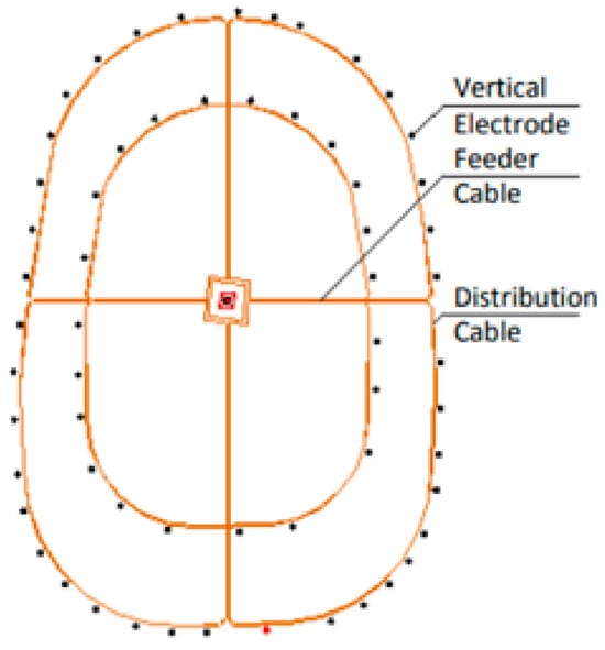
Figure 1.
Proposed ground scheme by CIGRE []. Figure reprinted with permission from CIGRE, General Guidelines for HVDC Electrode Design, ©2024.
This paper is organized into seven sections. Section 2 is devoted to the research gaps in the above literature survey. Section 3 describes the problem formulation. Section 4 presents the method of analysis. Section 5 describes the experimental setup and techniques. Section 6 reports the calculated and measured results and their discussions. Section 7 summarizes the main findings in the present paper.

Table 1.
A brief literature review of grounding schemes in AC power systems.
Table 1.
A brief literature review of grounding schemes in AC power systems.
| Ref. | Year | Experimental/Theoretical | Grid Geometry | Measurement Method | Calculation Method | Results | Soil Type |
|---|---|---|---|---|---|---|---|
| [] | 2004 | Theoretical | Earthing grid with dimensions | - | Finite element method, COMSOL Multiphysics | Ground resistance and surface potential | Uniform, two-layer, and multilayer soils |
| [] | 2018 | Theoretical | Earthing grid with dimensions | - | IEEE Std.80-2000 | Grid resistance, ground potential rise, mesh and step potential. | Multilayer soil |
| [] | 2013 | Theoretical | Earthing grid with dimensions | - | IEEE Std.80-2000 | Grid resistance, mesh, and step potential. | Uniform and multilayer soil |
| [] | 2014 | Experimental and theoretical | Earthing grid with dimensions | Wenner four-pole -method for soil resistivity measurements | CDEGS software | Ground resistance | Two-layer soil |
| [] | 2023 | Theoretical | Rod dimension with radius , length | - | ANSYS software | Ground resistance | Nonuniform, homogeneous soil |
| [] | 2023 | Theoretical | Earthing grid with unequal conductor spacing. | - | Modified Harris Hawks Optimizer | Ground resistance | Two-layer soil |
| [] | 2022 | Theoretical | Earthing grid with dimensions depth depth | - | Boundary element method | Grid resistance, ground potential rise, mesh and step potential. | Uniform soil |
| [] | 2022 | Experimental | Auxiliary circuits displaced vertically in the ground. | Grounding impedance measuring circuit using low-velocity propagation current | - | Transient impedance. | Uniform soil. |
| [] | 2021 | Experimental and theoretical | Earthing grid with dimensions , and buried at . | Ground resistance tester | CDEGS software | Ground resistance, step and touch potential. | Uniform soil. |
| [] | 2020 | Theoretical | Earthing grid with different shapes | - | Finite element method and genetic algorithm | Ground resistance, step and touch potential. | Multilayer soil |
| [] | 2018 | Experimental and theoretical | Earthing grid with dimensions | Current simulation method with point source | Grid resistance, mesh and step potential. | Multilayer soils. | |
| [] | 2012 | Theoretical | Earthing grid with dimensions | - | Current simulation method with point sources. | Ground resistance and earth surface potential. | Two-layer soil |
| [] | 2013 | Theoretical | Earthing grid with dimensions | - | Current simulation method with point sources. | Ground resistance and earth surface potential. | Two-layer soil |
| [] | 2013 | Theoretical | Earthing grid supported by vertical rods. and 75 m × 31.25 m | - | Current simulation with point sources. Software TOTBEM. | Ground resistance and earth surface potential | Homogeneous soil |
| [] | 2017 | Experimental | Earthing grid with dimensions 200 m × 150, 200 m × 100 | Conventional fall-of-potential | - | Ground resistance | Nonhomogeneous soil |
| [] | 2017 | Experimental and theoretical | Earthing grid with dimensions , provided with/without rods. | Wenner four-pole -method for soil resistivity measurements at selected sites. | Finite element method, CYMGRD Software | Ground resistance, touch, step and surface potential. | Wet and dry soil |
| [] | 2019 | Experimental and theoretical | Earthing grid with rod and plate electrodes buried vertically. | Wenner four-pole -method for soil resistivity measurements at selected sites. | Finite element method, COMSOL Multiphysics | Ground resistance, surface potential. | Uniform soil |
| [] | 2014 | Theoretical | Earthing grid with dimension | - | Finite element method, COMSOL Multiphysics | Ground resistance, surface potential. | Two-layer soil |
| [] | 2011 | Experimental | Earthing grid with dimension | Four-pole method for soil resistivity and fall of potential method for measuring ground resistance. | Finite element method, COMSOL Multiphysics | Ground resistance, touch, step, and surface potential. | Two-layer soil |
| [] | 2006 | Experimental and theoretical | S2emi-spherical of radius | Soil resistivity measurement by Wenner method and ground resistance using the fall-of-potential method | Finite-element method | Ground resistance, soil resistivity. | Uniform soil |
| [] | 2004 | Theoretical | Earthing grid with dimensions | - | Extremal charges method | Earth surface potential | Multilayer, homogeneous soil |
| [] | 1994 | Theoretical | Earthing grid with dimensions | Voltage and current measurements. | The method of images+ voltage and current measurements. | Ground resistance, touch, step and surface potential. | Uniform, two-layer soil |
| [] | 1998 | Experimental and theoretical | Earthing grid with dimensions | fall-of-potential method | Simulation by current sources. | Ground resistance | Two-layer soil |
2. Research Gaps
The above survey dictates that research work on grounding in HVDC systems in the literature is very limited when compared with that in the HVAC system. To the authors’ knowledge, there is no method supported in the literature to evaluate the ground resistance for a DC converter station based on the well-known charge simulation technique []. The equivalence concept of current conduction and electric field from the grounding scheme through the surrounding medium is applied for the first time for calculating the ground resistance of the DC converter station. This motivates the authors to apply the charge simulation technique to calculate the ground resistance for a DC converter station. Not only the ground resistance but also the potential distribution over the ground surface is calculated in the present paper for different depth values of the grounding scheme. The proposed grounding scheme for the converter station is aimed at improving the CIGRE scheme [], where the contours positioning the vertical ground rods are no longer elliptic but circular to ensure a more uniform distribution of the current delivered from the scheme into the surrounding soil. This is in addition to the simplification of the proposed charge simulation technique (CST) due to more symmetry in the proposed scheme.
3. Problem Formation
This article is aimed at proposing a method for calculating the ground resistance of a grounding scheme serving an HVDC substation. The proposed method is based on the charge simulation technique that utilizes the analogy between the conduction of electric flux lines in dielectric media and current density flow in conducting media. The effects of different parameters on the calculated ground resistance value are investigated. The ground resistance of the proposed grounding scheme and ground surface potentials are measured along a distance of four meters from the scheme’s center.
4. Method of Analysis
4.1. Geometry of the Grounding Scheme
The proposed grounding scheme is an extension to that proposed by CIGRE, as shown in Figure 1. A rodless ring is added to increase the contact surface area of the scheme with the soil. Therefore, the proposed scheme consists of a group of three concentric rings; named rodless, inner, and outer rings, which are located in a horizontal plane. The inner and outer rings are provided by a set of vertical rods uniformly distributed around the periphery of the ring. The inner ring has a radius , with four rods extending from it with rod length . The outer ring has a radius with four rods extending from it with rod length . Two perpendicular conductors in the plane of the rings divide them into four quarters, as shown in Figure 2. At each intersection point of the conductors with the inner and outer rings, there is a vertical rod. The radius of the rods and conductors are and , respectively.
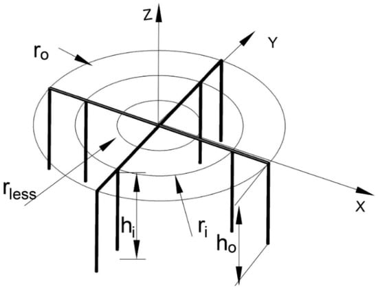
Figure 2.
Proposed grounding scheme.
Figure 2 of the proposed grounding scheme is quoted from the grounding of a wind turbine [] and from the ground return electrode stations for an HVDC transmissions system []. The vertical rods are tied to the outer ring electrodes. The rodless ring electrode is free from vertical rods because the outer ring electrodes shield the rodless one, so almost no current conduction to ground through the vertical rods occurs when tied to the rodless ring electrode []. It is the same as in grounding an electric substation using a grid, where vertical rods are tied only to the outer boundary of the grid. This is because vertical rods toward the center of the grid will not carry current to the ground, if any.
4.2. Simulation Technique
To evaluate the resistance-to-ground for the proposed grounding scheme, the equivalence of current conduction from the grounding scheme through the surrounding medium and electric flux flow from the scheme in a dielectric medium is utilized. To evaluate the flux flow, the well-known CST is applied to determine the flux density at the surface of the grounding scheme composed of rings, conductors, and rods. With the flow of a fault current in the grounding scheme, a voltage is developed on the scheme. The surface charges on the components of the grounding scheme are simulated by fictitious charges depending on the shape of the scheme components.
On stressing the geometry relative to the ground plane by an applied voltage , the resulting surface charge on the rings is simulated with three-ring charges and on the rods and conductors by finite line charges. For each simulation charge, a boundary point is selected on the electrode surface. A set of boundary points are located on each rod and conductor being modeled as finite-lines charges extending along their axes [,].
The equation expressing the potential at the ith point due to the simulation charges is expressed as , and is equal to the applied voltage
where is the number of simulation charges and is the number of boundary points, which may be equal to or greater than . is the potential coefficient calculated at the ith boundary point due to the jth simulation charge. Images of the simulation charges are considered and the potential coefficients for the ring and finite line charges are expressed as follows.
The potential coefficient at a point due to a ring charge with and , denoting ring radius and z-coordinate of the ring, is expressed as
where is the permittivity of the soil and and are elliptic integrals of the first kind.
The potential coefficient at a point , due to a finite line simulating vertical rods which extend along the Z-axis from to , is expressed as
where and are the z-coordinates of the start and end of the finite line charge provided that the line charge extends alone the Z-axis.
The potential coefficient at a point , due to a finite line simulating horizontal conductor which extends along the X-axis from to , is expressed as
where and are the x-coordinates of the start and end of the finite line charge provided that the line charge extends alone the X-axis.
The potential coefficient at a point , due to a finite line simulating horizontal conductor which extends along the Y-axis from to , is expressed as
where and are the y-coordinates of the start and end of the finite line charge provided that the line charge extends alone the Y-axis.
Equation (1) is applied at each boundary point to satisfy a pertinent boundary condition, which is the Dirichlet boundary condition. This formulates a set of equations, whose simultaneous solution determines the unknown simulation charges.
If the number of boundary points exceeds the number of simulation charges , the method of least squares [] is applied to formulate the set of describing equations.
To check the accuracy of the proposed charge CST, a set of checkpoints is chosen on the electrode surface midway between the boundary points. The potential deviation of the calculated potential from the applied voltage at the checkpoints is a measure of the accuracy of the proposed CST.
The ground resistance () is obtained from []
where is the capacitance of the grounding scheme as expressed by
where is the soil resistivity and ε is the soil permittivity. and are assumed uniform around the grounding scheme.
Figure 3 describes the flow chart of the charge simulation technique for calculating the ground resistance. First, the geometry of the grounding scheme is defined, the simulation charges for the grounding scheme are located, and then the charges are calculated. After this step, the potential error is checked; if this error is acceptable within a predefined tolerance, the electrical capacitance and hence the ground resistance is calculated. If not, the number and location of the fictitious simulation charges are modified, and the calculation procedure is repeated.
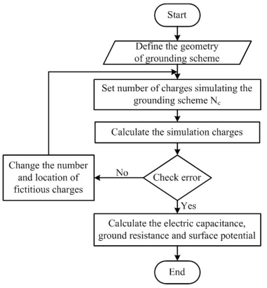
Figure 3.
Flow chart for ground resistance calculation using the CST.
As shown in Figure 2, the total number of rods is and each rod is simulated by finite line charges. Each of the two horizontal conductors is simulated by finite line charges. This is in addition to the three simulation ring charges. This adds up to a total of 155 simulation charges and a total of 155 boundary points.
For a parametric study, the electrical resistivity for soil has a range from to . The rods’ length has a range from to . The radius of the outer ring has a range from to against to for the inner ring.
5. Experimental Setup and Technique
In Figure 2, three-ring electrodes are made from bare copper conductors with a diameter of . The eight vertical rods are in diameter and in length. The depth of the rings of the grounding scheme is half a meter from ground level. The rings’ diameters are one, two, and three meters. Figure 4 shows the schematic diagram for the setup used to test the DC grounding scheme. The full-wave rectifier bridge injects a direct current into the DC grounding scheme for testing purposes.
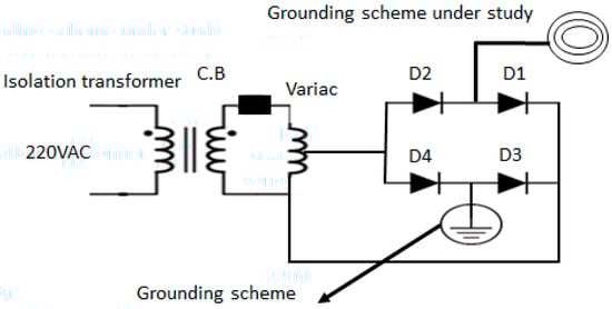
Figure 4.
Schematic diagram for setup circuit.
Figure 5 shows the experimental setup circuit with a Variac transformer that controls the AC voltage to the circuit, which is kept at 30 V. An analogue ammeter and voltmeter are used as shown in Figure 5 for the three-electrode method. The earth tester is to measure the surface potential.
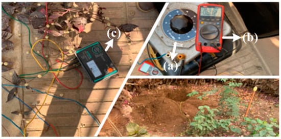
Figure 5.
Instruments and devices used in the experiment setup. (a) Variac transformer, (b) ampere, (c) earth tester.
The three-electrode method is one of the famous methods used to measure ground resistance. This method is applied for measuring ground resistance. One electrode is connected to the DC grounding scheme. The second one (current electrode ) is connected far away from the grounding scheme at a distance , and the third one (potential electrode Pe) is connected at a distance S1 equal to 62.5% of the whole distance , Figure 6. The voltage difference between the first and third rods is measured. The ground resistance is the potential difference divided by the DC injected current. The values of and are assigned to the distance and .
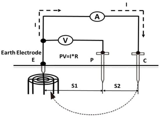
Figure 6.
Schematic diagram for the three-electrode method.
6. Results and Discussion
The satisfaction of the Dirichlet boundary conditions at all boundary points and the solution to the resulting equations determines the unknown simulation charges. The summation of all simulation charges and division of the sum by the applied voltage determines the capacitance of the ground scheme.
Table 2 lists the basic parameters used for the experimental setup including the values of soil permittivity and resistivity. These values represent approximately the mean values of those used for the parametric study.
Table 2.
Basic design parameters.
6.1. Accuracy of Simulation Technique
Figure 7 shows the percent potential error on the rods, which reaches a maximum value of , with checkpoints on the rods equal to ( rods; checkpoints per rod) as recorded on the horizontal axis of the figure and distributed over the eight rods in the sequence 1–18, 19–38, 37–54, 55–72, 73–90, 91–108, 109–126 and 127–144. The checkpoints on each rod start from top to bottom.
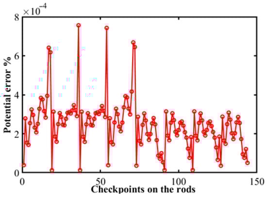
Figure 7.
Potential error at rods at the different checkpoints. (, , .
Figure 8 shows the percent potential error on the conductors, which reaches a maximum value of with eight checkpoints on the rods numbered 145–152 with four points numbered 145–148 at a radial distance equal to and four points with numbers 149–152 at a radial distance equal to .
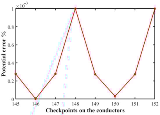
Figure 8.
Potential error at the conductors at the different checkpoints. (, , ,
).
Figure 9 shows the percentage potential error on the rings, which reaches a maximum value of with checkpoints numbered on the intersection point of the rodless ring with the x-axis, on the inner ring but shifted from the x-axis, and on the outer ring but shifted from the x-axis. It is worth mentioning that the percent error in Figure 9 over the ring electrodes is calculated at specific checkpoints, where the error records a maximum value.
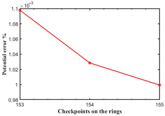
Figure 9.
Potential error at the rings at the different checkpoints. .
6.2. Ground Resistance as Influenced by Grounding-Scheme Parameters
Figure 10 shows the effects of changing the rod diameter on the calculated parameter ground resistance values. The relationship is inversely proportional between the rod diameter and the ground resistance, the larger the rod diameter, the more the contact area of the rods with the soil. This is reflected in the decreasing with increasing rod diameter, as indicated in Figure 10.
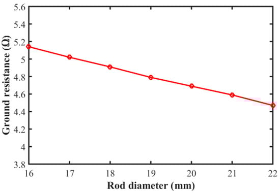
Figure 10.
Effect of rods’ diameter on the ground resistance. .
By applying Equation (6), the ground resistance is calculated to be equal to , which is very close to the measured value of with an error value of . By using the CYMGRD, the ground resistance of the proposed grounding scheme records . This indicates the accuracy of the proposed simulation of the grounding scheme and enhances the confidence in the proposed method of analysis.
The measurements of the ground resistance do not fit well with the numerical calculations, which assume uniform soil resistivity. These calculations predict values that vary depending on the used formula or the adopted technique for evaluating the ground resistance []. As an example, the ground resistance of a single rod (one of those used in the proposed grounding scheme of Figure 2) of 1.2 m in length which is flush with the surface of the soil with resistivity has values of (i) 24.96 and 23.57 with a percent decrease of 5.58% on increasing the rod diameter from 16 mm to 22 mm by using the Rudenberg formula [], (ii) 23.62 and 22.227 with a percent decrease of 5.9% by using the Dwight–Sunde formula [], (iii) 21.95 and 20.576 with a percent decrease of 6.25% by using Liew–Darveniza [], and (iv) 25.2 and 23.45 with a percent decrease of 6.95% by using CYMGRD software.
Figure 11 presents the influence of varying the rod length on the ground resistance with . The relationship is inversely proportional between the rod length and the ground resistance. The same as in Figure 10, increasing the rod length increases the contact area of the grounding scheme with the surrounding soil with a subsequent decrease in with an increase in rod length or .
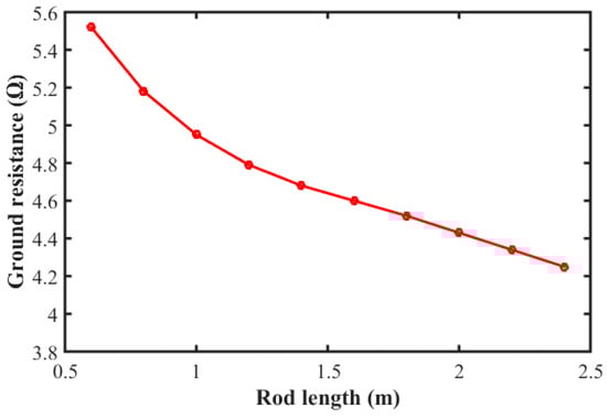
Figure 11.
Effect of the rods’ length on the ground resistance. .
Figure 12 shows how the ground resistance decreases with an increase in the inner radius in the range from to . Of course, the increase in of the inner ring results in increasing the contact area of the grounding scheme with the soil with a subsequent decrease in , as shown in Figure 11. The minimum resistance value corresponds to a radius equal to .
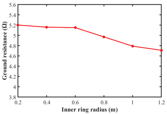
Figure 12.
Effect of varying the inner ring radius on the ground resistance. .
Figure 13 shows the effect of increasing the radius of the outer ring on the ground resistance. It is clear that the lowest value equals at a radius equal to three meters. Of course, an increase in of the outer ring results in increasing the contact area of the grounding scheme with the soil with a subsequent decrease in , as shown in Figure 13.
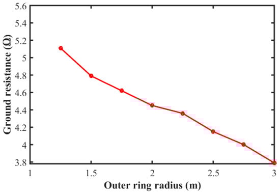
Figure 13.
Effect of varying the outer ring radius on the ground resistance. .
Figure 14 presents the calculated ground resistance values for different types of soil with resistivity values given in Table 3. Sea water is the best-conducting medium to achieve a minimum ground resistance value because sea water has the lowest resistivity value.
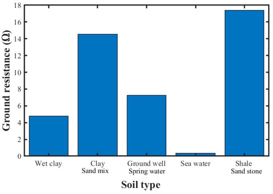
Figure 14.
Ground resistance for different soil types (, , .
Table 3.
Different types of soil resistivities [].
Figure 15 shows the decrease in the ground resistance with the increase in the length of the outer rod. This is the same as discussed for the effect of the increase in the rod length in Figure 11, and the effect of the increase in the inner and outer rings in Figure 12 and Figure 13 on decreasing the ground ; it also decreases with the increase in the length of the outer rods.
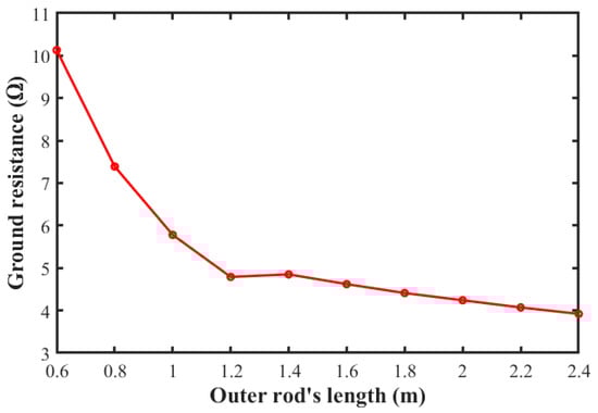
Figure 15.
Ground resistance value versus the length of the rods for outer ring ,
.
6.3. Surface Potential
Figure 16 shows the measured and calculated potential values at the ground surface starting from the center of the grounding scheme, provided that the DC voltage is applied at the center of the scheme. The maximum value at the center of the electrode is and decreases in the direction away from the grounding scheme and reaches at a distance of . The deviation of the calculated surface-potential value from those measured experimentally has an average value of .
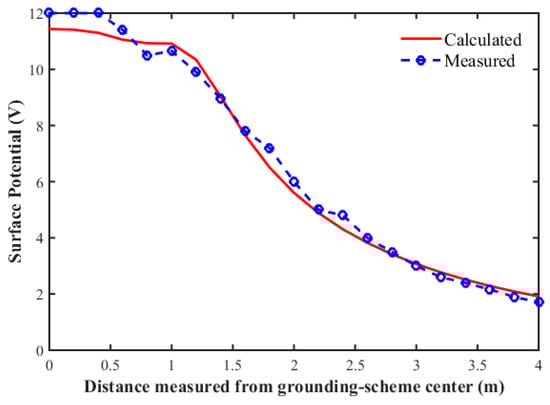
Figure 16.
Measured and calculated surface potential versus the distance from the center of the grounding scheme ,
.
Figure 17 shows the calculated surface-potential distribution over the ground plane at different depths values of the grounding scheme into the soil. At a depth equal to , the maximum surface-potential value is , and decreases to on increasing the depth to against at depth of . This is because the increase in depth results in increasing the spacing between the simulation charges of the grounding scheme and the ground surface. The larger the spacing, the smaller the potential values at the ground surface, as shown in Figure 17.
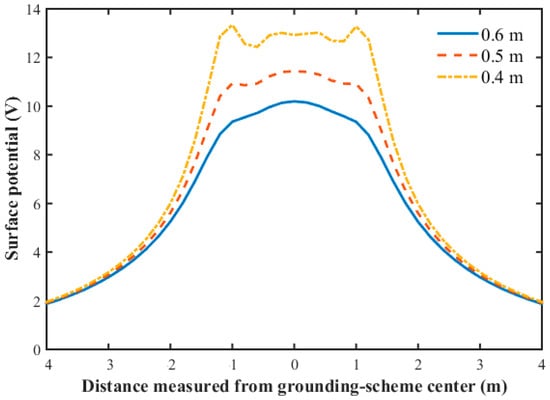
Figure 17.
Surface-potential values over the ground plane at different depth values of the scheme rings. ,
.
7. Conclusions
This paper presents a method for calculating the ground resistance of a grounding scheme servicing a DC converter station. The method is based on the charge simulation technique and is considered a valuable approach for engineers in charge of designing and analyzing DC grounding schemes. Lower ground resistance values can be achieved by increasing the number of rods, conductors, and rings. Therefore, the present paper improves the grounding scheme proposed by CIGRE [], seeking a decrease in the grounding resistance of the converter station in DC systems. The improvement is achieved by adding the rodless ring electrode to increase the contact surface area of the grounding scheme with the surrounding soil.
This paper studied the effects of different parameters affecting the ground resistance, such as the rod diameter, radius of the ring, etc., which express the geometry of the grounding station. The obtained results recommend a suitable depth and diameter of the grounding rods to achieve a design value of the ground resistance. Generally speaking, the larger the contact area of the grounding scheme with the soil, the lower the ground resistance of the scheme.
The calculated ground resistance agreed reasonably well with that obtained experimentally with an error value of . The calculated surface-potential values agreed with those measured experimentally with an average percent error not exceeding %.
The maximum percent potential error on the rods, conductors, and ring electrodes recorded values of , and , respectively. This is reflected in the accuracy of the adopted charge simulation technique.
An increase in rod diameter from 16 mm to 22 mm resulted in a decrease in the ground resistance by about 13%, and an increase in rod length from 0.6 m to 2.4 m resulted in a decrease in the ground resistance by about 22%.
An increase in the radius of the inner ring from 0.2 m to 1.2 m resulted in a decrease in the ground resistance by 9%, and an increase in the radius of the outer ring from 1.25 m to 3 m resulted in a decrease in the ground resistance by 25%.
Author Contributions
Conceptualization, S.A. and H.H.E.-H.; Methodology, S.A.; Software, S.A. and H.H.E.-H.; Formal analysis, S.A. and H.H.E.-H.; Investigation, S.A.; Resources, S.A.; Writing—original draft, S.A. and H.H.E.-H.; Writing—review & editing, S.A. and H.H.E.-H.; Supervision, A.M.K.E.-M., M.M.S. and A.M.E. All authors have read and agreed to the published version of the manuscript.
Funding
This research received no external funding.
Data Availability Statement
Data are contained within the article.
Conflicts of Interest
The authors declare no conflict of interest.
Abbreviations
| Electrical capacitance | |
| Circuit breaker | |
| Current electrode | |
| CST | Charge simulation technique |
| Rectification diodes | |
| Grounding scheme | |
| HVDC | High-voltage direct current |
| Length of inner rod | |
| Length of outer rod | |
| Depth of rings forming the grounding scheme | |
| IEC | International electrotechnical commission |
| Conductor length | |
| Number of simulation charges | |
| Number of check points/Number of check points | |
| Potential coefficient | |
| Potential electrode | |
| Potential due to the simulation charges at the ith boundary point. | |
| Radius of inner ring | |
| Radius of outer ring | |
| Radius of rodless ring; | |
| Resistance of grounding scheme | |
| Rod radius | |
| Conductor radius | |
| Distance between grounding scheme and potential electrode | |
| Distance between current electrode and potential electrode | |
| Voltage Applied | |
| Soil resistivity | |
| Soil permittivity |
References
- Stockin, D.R. Grounding and Earthing Handbook, 1st ed.; McGraw-Hill’s: New York, NY, USA, 2014; ISBN 978-0-07-180065-5. [Google Scholar]
- Kimbark, E.W. Direct Current Transmission, 1st ed.; Wiley: New York, NY, USA, 1971. [Google Scholar]
- CIGRE Working Group. General Guidelines for HVDC Electrode Design; CIGRÉ: Paris, France, 2017; ISBN 9782858733781. [Google Scholar]
- Aljohani, T.M.; Alzahrani, A.M. The Operation of the GCCIA HVDC Project and Its Potential Impacts on the Electric Power Systems of the Region. Int. J. Electron. Electr. Eng. 2014, 2, 207–213. [Google Scholar] [CrossRef]
- IEC TS 60479-1; Effects of Current on Human Beings and Livestock—Part 1: General Aspects. International Electrotechnical Commission: Geneva, Switzerland, 2016.
- Meliopoulos, A.P.S. Power System Grounding and Transients: An Introduction, 1st ed.; Marcel Dekker Inc.: New York, NY, USA, 1988. [Google Scholar]
- Li, B.; Li, C.; Li, B.; Wen, W. Study on the distributed-parameter resistance earth model and potential distribution of the monopole-ground-return HVDC. Electr. Power Syst. Res. 2020, 187, 106478. [Google Scholar] [CrossRef]
- Pratama, R.A.; Hermawan; Facta, M. Analysis of Grounding System in 150 kV Kudus Substation. In Proceedings of the 2018 5th International Conference on Information Technology, Computer, and Electrical Engineering (ICITACEE), Semarang, Indonesia, 27–28 September 2018; pp. 245–250. [Google Scholar]
- Kushare, B.E.; Unde, M.G. Impact of seasonal variation of soil resistivity on safety of substation grounding system. In Proceedings of the Fifth International Conference on Advances in Recent Technologies in Communication and Computing (ARTCom 2013), Bangalore, India, 20–21 September 2013; Institution of Engineering and Technology: Lucknow, India, 2013; pp. 173–182. [Google Scholar]
- Singer, H.; Steinbigler, H.; Weiss, P. A Charge Simulation Method for the Calculation of High Voltage Fields. IEEE Trans. Power Appar. Syst. 1974, PAS-93, 1660–1668. [Google Scholar] [CrossRef]
- Guizán, R.; Colominas, I.; París, J.; Couceiro, I.; Navarrina, F. Numerical analysis and safety design of grounding systems in underground compact substations. Electr. Power Syst. Res. 2022, 203, 107627. [Google Scholar] [CrossRef]
- Ghoneim, S.S.M. Charge and Current Simulation Method with Boundary Element Method for Grounding System Calculations in Case of MultiLayer Soil. IOSR J. Eng. 2013, 03, 14–22. [Google Scholar] [CrossRef]
- Ghoneim, S.S.M. Analytical methods of earth surface potential calculation for grounding grids. Int. J. Eng. Comput. Sci. 2013, 13, 3–47. [Google Scholar]
- Güemes, J.A.; Hernando, F.E. Method for calculating the ground resistance of grounding grids using FEM. IEEE Trans. Power Deliv. 2004, 19, 595–600. [Google Scholar] [CrossRef]
- Cai, Y.; Ji, H.; Wang, D.; Lei, X.; Sun, Y.; Yuan, S. Optimal construction method and demonstration application of multi-in-one station grounding system. Glob. Energy Interconnect. 2021, 4, 520–530. [Google Scholar] [CrossRef]
- Freire, P.; Kalife, J.; Oliveira, G. Rio Madeira HVDC System: Commissioning of the Ground Electrode for Bipole 2 at Porto Velho. Appl. Sci. 2022, 12, 3279. [Google Scholar] [CrossRef]
- Kwon, H.; Kil, Y.; Kim, S. A method for grounding resistance calculation of vertical electrode. Electr. Power Syst. Res. 2023, 224, 109718. [Google Scholar] [CrossRef]
- Wen, X.; Jing, M.; Cai, H.; Zhang, Y.; Hu, S.; Teng, Y.; Liu, G.; Lan, L.; Lu, H. Temperature characteristics and influence of water-saturated soil resistivity on the HVDC grounding electrode temperature rise. Int. J. Electr. Power Energy Syst. 2020, 118, 105720. [Google Scholar] [CrossRef]
- Salam, M.A.; Rahman, Q.M.; Ang, S.P.; Wen, F. Soil resistivity and ground resistance for dry and wet soil. J. Mod. Power Syst. Clean Energy 2017, 5, 290–297. [Google Scholar] [CrossRef]
- Paulo, P.E.; Pereira, S.Y.; Padilha, A.L. Adjustment of a crustal geoelectric model from Commissioning data of HVDC ground electrodes: A case study from the Northeastern Paraná Basin, Brazil. J. Appl. Geophys. 2020, 182, 104186. [Google Scholar] [CrossRef]
- Bhosale, M.J.; Karandikar, P.B.; Kulkarni, N.R. An optimal design for grounding grid configuration with unequal conductor spacing. Adv. Eng. Softw. 2023, 176, 103367. [Google Scholar] [CrossRef]
- Guimarães, M.F.; Paulino, J.O.S.; Caetano, C.E.F.; Barbosa, C.F.; Boaventura, W.C. Grounding measurements using auxiliary circuits disposed vertically in the ground. Electr. Power Syst. Res. 2022, 213, 108727. [Google Scholar] [CrossRef]
- Buba, S.D.; Wan Ahmad, W.F.; Ab Kadir, M.Z.A.; Gomes, C.; Jasni, J.; Osman, M. Design of distribution substation earth grid in high resistivity soil using CDEGS. In Proceedings of the 2014 IEEE 8th International Power Engineering and Optimization Conference, PEOCO 2014, Langkawi, Malaysia, 24–25 March 2014; IEEE Computer Society: Washington, DC, USA, 2014; pp. 508–513. [Google Scholar]
- Trifunovic, J.; Kostic, M. Analysis of influence of imperfect contact between grounding electrodes and surrounding soil on electrical properties of grounding loops. Electr. Eng. 2014, 96, 255–265. [Google Scholar] [CrossRef]
- Mondal, D.; Dey, S.; Pradhan, A.K.; Das, S. Earthing grid designs for heterogeneous soil structures in hilly regions using current simulation method. IET Gener. Transm. Distrib. 2018, 12, 3021–3027. [Google Scholar] [CrossRef]
- Zaini, H.G.; Ghoneim, S.S. Earth surface potential and grounding resistance for grounding grid in two-layer model soil. In Proceedings of the 2012 IEEE International Conference on Power System Technology (POWERCON), Auckland, New Zealand, 30 October–2 November 2012; pp. 1–5. [Google Scholar]
- Colella, P.; Pons, E.; Tommasini, R.; Silvestre, M.L.D.; Sanseverino, E.R.; Zizzo, G. Fall of potential measurement of the earth resistance in urban environments: Accuracy evaluation. IEEE Trans. Ind. Appl. 2019, 55, 2337–2346. [Google Scholar] [CrossRef]
- Wang, C.-g.; Takasima, T.; Sakuta, T.; Tsubota, Y. Grounding resistance measurement using fall-of-potential method with potential probe located in opposite direction to the current probe. IEEE Trans. Power Deliv. 1998, 13, 1128–1135. [Google Scholar] [CrossRef]
- Yuan, T.; Bai, Y.; Sima, W.; Xian, C.; Peng, Q.; Guo, R. Grounding resistance measurement method based on the fall of potential curve test near current electrode. IEEE Trans. Power Deliv. 2017, 32, 2005–2012. [Google Scholar] [CrossRef]
- Güemes-Alonso, J.A.; Hernando-Fernández, F.E.; Rodríguez-Bona, F.; Ruiz-Moll, J.M. A practical approach for determining the ground resistance of grounding grids. IEEE Trans. Power Deliv. 2006, 21, 1261–1266. [Google Scholar] [CrossRef]
- Dawalibi, F.P.; Ma, J.; Southey, R.D. Behaviour of grounding systems in multilayer soils: A parametric analysis. IEEE Trans. Power Deliv. 1994, 9, 334–342. [Google Scholar] [CrossRef]
- Salam, M.A.; Jen, K.M.; Khan, M.A. Measurement and simulation of grounding resistance with two and four mesh grids. In Proceedings of the 2011 IEEE Ninth International Conference on Power Electronics and Drive Systems, Singapore, 5–8 December 2011; pp. 208–213. [Google Scholar]
- Bendito, E.; Carmona, Á.; Encinas, A.M.; Jiménez, M.J. The Extremal Charges Method in Grounding Grid Design. IEEE Trans. Power Deliv. 2004, 19, 118–123. [Google Scholar] [CrossRef]
- Li, W.; Pan, Z.; Lu, H.; Chen, X.; Zhang, L.; Wen, X. Influence of deep earth resistivity on HVDC ground-return currents distribution. IEEE Trans. Power Deliv. 2017, 32, 1844–1851. [Google Scholar] [CrossRef]
- Ma, C.; Zhao, S.; Sun, L.; Wang, L.; Zhang, G. The Simulation Study of DC Grounding Electrode Based on CDEGS and ANSYS. J. Phys. Conf. Ser. 2018, 1072, 012006. [Google Scholar] [CrossRef]
- Zhang, B.; Zeng, R.; He, J.; Zhao, J.; Li, X.; Wang, Q.; Cui, X. Numerical analysis of potential distribution between ground electrodes of HVDC system considering the effect of deep earth layers. IET Gener. Transm. Distrib. 2008, 2, 185–191. [Google Scholar] [CrossRef]
- Dan, Y.; Zhang, Z.; Zhao, H.; Li, Y.; Ye, H.; Deng, J. A novel segmented sampling numerical calculation method for grounding parameters in horizontally multilayered soil. Int. J. Electr. Power Energy Syst. 2021, 126, 106586. [Google Scholar] [CrossRef]
- Peiyu, H.; Peng, L.; Qingjun, P.; Min, C.; Hu, Y.; Bo, L. Calculation model for the earth potential of HVDC ground electrode based on image recognition of surface-layer soil moisture. Meas. Control 2020, 53, 1682–1693. [Google Scholar] [CrossRef]
- Sengar, K.P.; Chandrasekaran, K. Effects of cost optimised grid configuration on earthing system performance: A comparative assessment. IET Sci. Meas. Technol. 2020, 14, 610–620. [Google Scholar] [CrossRef]
- Zalhaf, A.S.; Ahmed, M.; Ookawara, S.; Abdel-Salam, M. A Simplified Model of Wind Turbine for Lightning Transient Analysis as Influenced by Structure of Grounding System. In Proceedings of the 2018 5th International Conference on Electric Power and Energy Conversion Systems (EPECS), Kitakyushu, Japan, 23–25 April 2018; pp. 1–6. [Google Scholar]
- Eaton, J.R. Electric Power Transmission Systems; Prentice-Hall: Lansing, MI, USA, 1972; ISBN 9780132473040. [Google Scholar]
- El-Hawary, H.H.; Abdel-Salam, M.; Hashem, A.A.R.; Turky, A.H.A. Inception Voltage of Burst Pulses, Onset Streamers, and Positive Glow in Short Rod-to-Plane Gaps. IEEE Trans. Plasma Sci. 2021, 49, 1763–1775. [Google Scholar] [CrossRef]
- Burden, R.L.; Faires, J.D. Numerical Analysis, 9th ed.; Brooks/Cole, Cengage Learning: Boston, MA, USA, 2011; ISBN 9780538733519. [Google Scholar]
- Bouderballa, A.; Zegnini, B.; Seghier, T. Determination of the resistance of a grounding system with application of finite element method. Prz. Elektrotechniczny 2021, 97, 5–11. [Google Scholar]
- Rüdenberg, R. Grounding principles and practice I—Fundamental considerations on ground currents. Electr. Eng. 1945, 64, 1–13. [Google Scholar] [CrossRef]
- Dwight, H.B. Calculation of Resistances to Ground. Trans. Am. Inst. Electr. Eng. 1936, 55, 1319–1328. [Google Scholar] [CrossRef]
- Liew, A.C.; Darveniza, M. Dynamic model of impulse characteristics of concentrated earths. Proc. Inst. Electr. Eng. 1974, 121, 123. [Google Scholar] [CrossRef]
- Dafalla, M.A.; AlFouzan, F.A. Influence of physical parameters and soil chemical composition on electrical resistivity: A guide for geotechnical soil profiles. Int. J. Electrochem. Sci. 2012, 7, 3191–3204. [Google Scholar] [CrossRef]
Disclaimer/Publisher’s Note: The statements, opinions and data contained in all publications are solely those of the individual author(s) and contributor(s) and not of MDPI and/or the editor(s). MDPI and/or the editor(s) disclaim responsibility for any injury to people or property resulting from any ideas, methods, instructions or products referred to in the content. |
© 2024 by the authors. Licensee MDPI, Basel, Switzerland. This article is an open access article distributed under the terms and conditions of the Creative Commons Attribution (CC BY) license (https://creativecommons.org/licenses/by/4.0/).