Improving the Economic Efficiency of Heat Pump Integration into Distillation Columns of Process Plants Applying Different Pressures of Evaporators and Condensers
Abstract
:1. Introduction
2. Materials and Methods
- A definition of the process streams that should be heated and cooled by the heat pump with the use of the GCC (Figure 1);
- The placement of the heat pump and the initial energy targets for both thermal energy and power, specifying the current (∆Tmin) between process and utility (refrigerant);
- A simulation of the heat pump in the Aspen HYSYS 12 [51] environment under an acceptable pressure drop in the condenser and reboiler;
- The calculation of the detailed configurations and capital costs of the condenser and reboiler based on the simulation results;
- The calculation of the compressor’s capital cost;
- The calculation of the annualised capital cost of the HP equipment using the cost factors;
- The calculation of the total annualised cost (TAC);
- Changing the refrigerant pressure in the compressor inlet/outlet and a repetition of the previous steps;
- The selection of the HP configuration with min TAC;
- Performing a sensitivity analysis of the results by applying different electricity prices.
3. The Case Study
3.1. Process Description
3.2. Scenarios
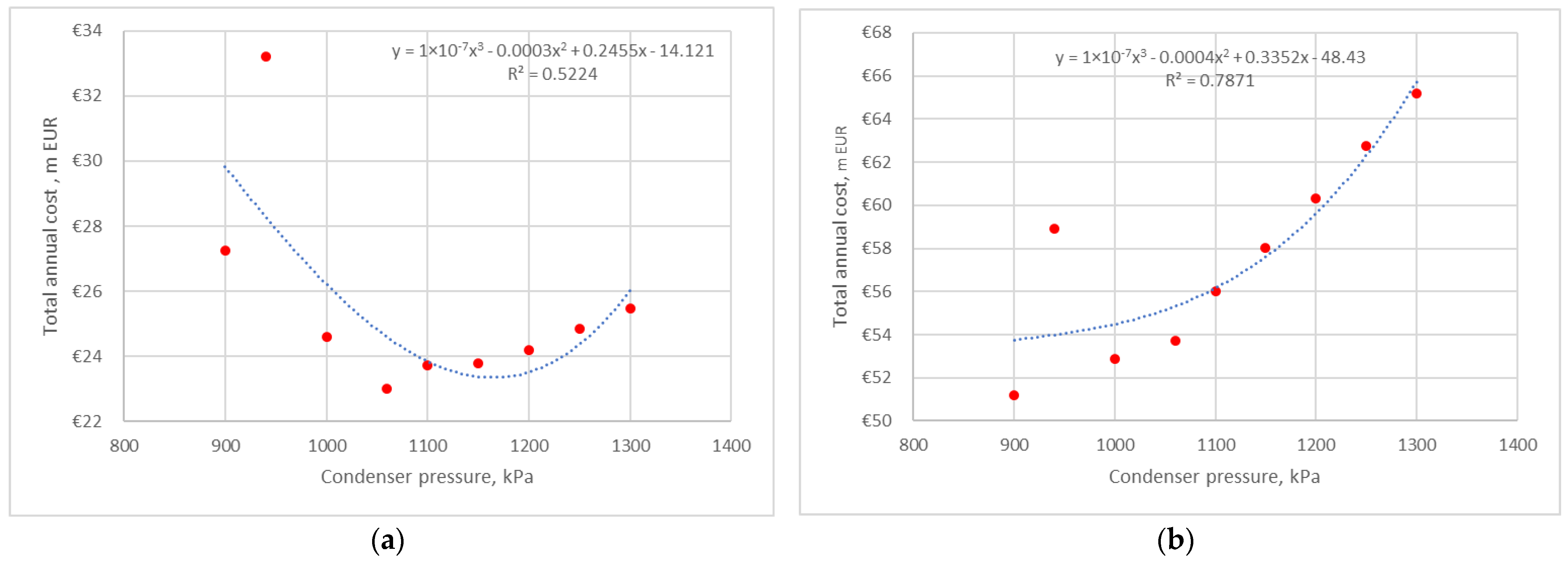
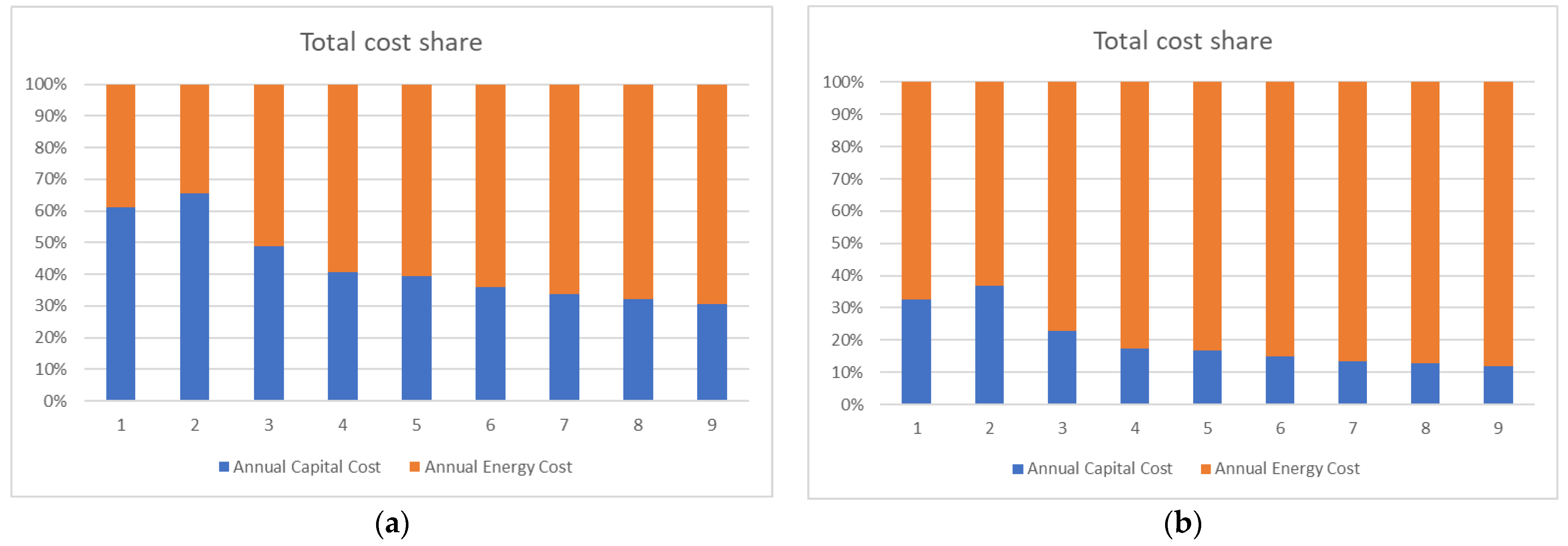
3.2.1. Scenario 1: Constant Pressure at the Evaporator and Varied Pressure at the Condenser
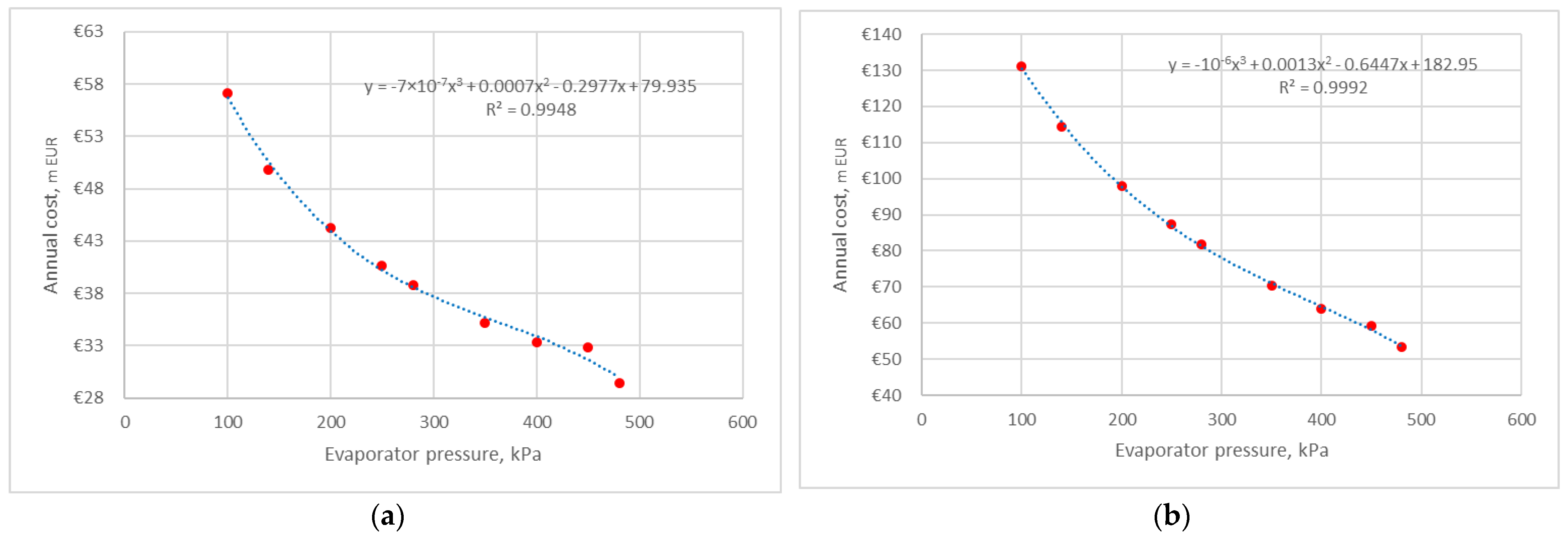
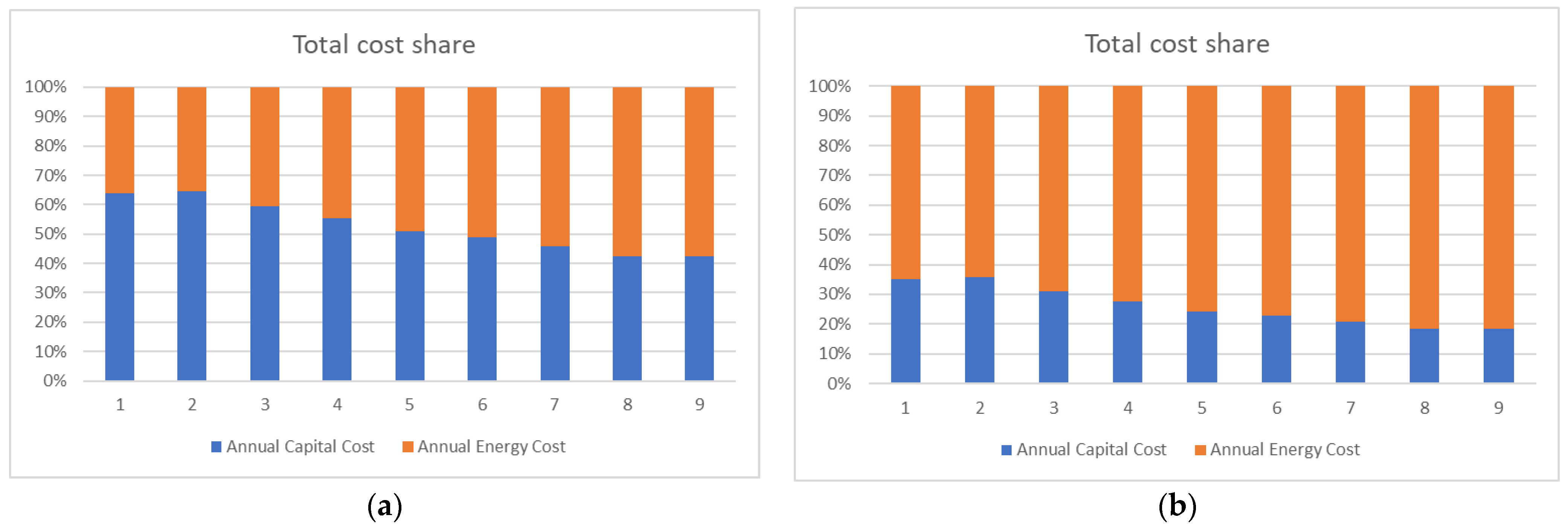
3.2.2. Scenario 2: Constant Pressure at the Condenser and Varied Pressure at the Evaporator
3.2.3. Scenario 3: Both the Evaporator and Condenser Pressure of the Heat Pump Are Varied
3.3. Variables and Constraints
- Y = 8670 h;
- Lang = 4.72;
- FIR = 0.1;
- NY = 7 years;
- ce min = 0.12 EUR/kWh (minimal EU price), ce avg = 0.21 EUR/kWh (average EU price), ce max = 0.39 EUR/kWh (maximal EU price) [54];
- Condenser pressure;
- Evaporator pressure;
- Compressor power;
- COP;
- Heat transfer area of the condenser;
- Heat transfer area of the evaporator.
- Minimum pressure at the compressor inlet: 101.3 kPa;
- Maximum pressure at the compressor inlet of HP-1: 480 kPa;
- Maximum pressure at the compressor inlet of HP-2: 420 kPa;
- Maximum pressure at the compressor inlet of HP-3: 380 kPa;
- Minimum pressure at the compressor outlet of HP-1: 900 kPa;
- Minimum pressure at the compressor outlet of HP-2: 900 kPa;
- Minimum pressure at the compressor outlet of HP-3: 2000 kPa;
- The acceptable condenser pressure drop (tubes/shell) is 5 kPa;
- The acceptable evaporator pressure drop (tube/shell) is 5 kPa;
- Compressor efficiency (adiabatic) is 75%;
- Heat exchanger type is shell-and-tube for both evaporator and condenser;
- Tube type is plain;
- The tube material is carbon steel.
- D_FXPRIV.PDA Private properties chemical databank properties;
- D_IDPRIV.PDA Private properties chemical databank index;
- D_VAPRIV.PDA Private properties chemical databank properties;
- N_MTLDEF.PDA Default materials for generic materials (ASME);
- N_MTLDIN.PDA Default materials for generic materials (DIN);
- N_MTLCDP.PDA Default materials for generic materials (AFNOR);
- N_PARTNO.PDA Part number assignment for the bill of materials;
- N_PRIVI.PDA Private properties materials databank index;
- N_PRIVP.PDA Private properties materials databank properties;
- N_STDLAB.PDA Fabrication standards, procedures, costs, etc.;
- N_STDMTL.PDA Fabrication standards as function of materials;
- N_STDOPR.PDA Fabrication operation efficiencies;
- N_STDWLD.PDA Fabrication welding standards;
- N_STDPRC.PDA Private materials prices.
4. Results and Discussion
4.1. Heat Pump 1
4.1.1. Average Electricity Price
4.1.2. Sensitivity for Min and Max Electricity Prices
4.2. Heat Pump 2
4.2.1. Average Electricity Price
4.2.2. Sensitivity for Min and Max Electricity Prices
4.3. Heat Pump 3
4.3.1. Average Electricity Price
4.3.2. Sensitivity for Min and Max Electricity Prices
4.4. Impact of the Results
5. Conclusions
Author Contributions
Funding
Data Availability Statement
Conflicts of Interest
Nomenclature
| Heat transfer area (m2) | |
| Annual capital cost (EUR/y) | |
| Electricity prices (EUR/kWh) | |
| Evaporator capital cost (EUR) | |
| Compressor capital cost (EUR) | |
| Condenser capital cost (EUR) | |
| Coefficient of performance (n/d) | |
| Outside diameter of tube (m) | |
| Annual energy cost (EUR/y) | |
| Correction factor for design temperature (n/d) | |
| Correction factor for design pressure (n/d) | |
| Correction factor for construction materials (n/d) | |
| Fractional interest rate per year (%) | |
| Correction factor of heat transfer (n/d) | |
| Gravitational constant (9.81 m·s−2) | |
| Condensing film coefficient (W·m−2·K−1) | |
| Enthalpy of the inlet stream (kJ kg−1) | |
| Enthalpy of the outlet stream (kJ kg−1) | |
| Nucleate boiling coefficient (W·m−2·K−1) | |
| Number of process streams, (n/d) | |
| Thermal conductivity of the liquid (W·m−1·K−1) | |
| Lang factor (n/d) | |
| Mass flow of the inlet stream (kg h−1) | |
| Mass flow of the outlet stream (kg h−1) | |
| Losses of mass flows (kg h−1) | |
| Bank loan period (y) | |
| Operating pressure (kPa) | |
| Liquid critical pressure (kPa) | |
| Heat duty (W) | |
| Heat flux (W·m−2) | |
| Heat absorbed by heat pump at low temperature (W) | |
| Energy losses (W) | |
| Total annual cost (EUR/y) | |
| Inlet temperature of the cold stream (°C) | |
| Inlet temperature of the hot stream (°C) | |
| Outlet temperature of the cold stream (°C) | |
| Outlet temperature of the hot stream (°C) | |
| Heat transfer coefficient (W·m−2·K−1) | |
| Power (W) | |
| Latent heat (J·kg−1) | |
| Logarithmic temperature difference (°C) | |
| Temperature difference across the condensate film (°C) | |
| Viscosity of the liquid (kg·m−1·s−1) | |
| Density of the liquid (kg·m−3) |
Appendix A
References
- Barkaoui, A.-E.; Boldyryev, S.; Duic, N.; Krajacic, G.; Guzović, Z. Appropriate Integration of Geothermal Energy Sources by Pinch Approach: Case Study of Croatia. Appl. Energy 2016, 184, 1343–1349. [Google Scholar] [CrossRef]
- Mészáros, I.; Fonyó, Z. Design Strategy for Heat Pump Assisted Distillation System. J. Heat Recovery Syst. 1986, 6, 469–476. [Google Scholar] [CrossRef]
- van de Bor, D.M.; Infante Ferreira, C.A.; Kiss, A.A. Low Grade Waste Heat Recovery Using Heat Pumps and Power Cycles. Energy 2015, 89, 864–873. [Google Scholar] [CrossRef]
- Yuan, G.; Chu, K.H. Heat Pump Drying of Industrial Wastewater Sludge. Water Pract. Technol. 2020, 15, 404–415. [Google Scholar] [CrossRef]
- Tveit, T.-M. Application of an Industrial Heat Pump for Steam Generation Using District Heating as a Heat Source. 12the IEA Heat Pump Conference, Rotterdam, O.3.8.3. 2017. Available online: https://heatpumpingtechnologies.org/publications/o-3-8-3-application-of-an-industrial-heat-pump-for-steam-generation-using-district-heating-as-a-heat-source/ (accessed on 30 January 2024).
- Byrne, P.S.; Carton, J.G.; Corcoran, B. Investigating the Suitability of a Heat Pump Water-Heater as a Method to Reduce Agricultural Emissions in Dairy Farms. Sustainability 2021, 13, 5736. [Google Scholar] [CrossRef]
- Hermanucz, P.; Geczi, G.; Barotfi, I. Energy Efficient Solution in the Brewing Process Using a Dual-Source Heat Pump. Therm. Sci. 2022, 26, 2311–2319. [Google Scholar] [CrossRef]
- Anifantis, A.; Colantoni, A.; Pascuzzi, S.; Santoro, F. Photovoltaic and Hydrogen Plant Integrated with a Gas Heat Pump for Greenhouse Heating: A Mathematical Study. Sustainability 2018, 10, 378. [Google Scholar] [CrossRef]
- Nemś, A.; Nemś, M.; Świder, K. Analysis of the Possibilities of Using a Heat Pump for Greenhouse Heating in Polish Climatic Conditions—A Case Study. Sustainability 2018, 10, 3483. [Google Scholar] [CrossRef]
- Słyś, D.; Pochwat, K.; Czarniecki, D. An Analysis of Waste Heat Recovery from Wastewater on Livestock and Agriculture Farms. Resources 2020, 9, 3. [Google Scholar] [CrossRef]
- Babak, T.; Duić, N.; Khavin, G.; Boldyryev, S.; Krajačić, G. Possibility of Heat Pump Use in Hot Water Supply Systems. J. Sustain. Dev. Energy Water Environ. Syst. 2016, 4, 203–215. [Google Scholar] [CrossRef]
- Ünal, F.; Akan, A.E.; DemïR, B.; Yaman, K. 4E Analysis of an Underfloor Heating System Integrated to the Geothermal Heat Pump for Greenhouse Heating. Turk. J. Agric. For. 2022, 46, 762–780. [Google Scholar] [CrossRef]
- Chiriboga, G.; Capelo, S.; Bunces, P.; Guzmán, C.; Cepeda, J.; Gordillo, G.; Montesdeoca, D.E.; Carvajal, C.G. Harnessing of Geothermal Energy for a Greenhouse in Ecuador Employing a Heat Pump: Design, Construction, and Feasibility Assessment. Heliyon 2021, 7, e08608. [Google Scholar] [CrossRef]
- Zhang, H.; Liu, Y.; Liu, X.; Duan, C. Energy and Exergy Analysis of a New Cogeneration System Based on an Organic Rankine Cycle and Absorption Heat Pump in the Coal-Fired Power Plant. Energy Convers. Manag. 2020, 223, 113293. [Google Scholar] [CrossRef]
- Cao, X.-Q.; Yang, W.-W.; Zhou, F.; He, Y.-L. Performance Analysis of Different High-Temperature Heat Pump Systems for Low-Grade Waste Heat Recovery. Appl. Therm. Eng. 2014, 71, 291–300. [Google Scholar] [CrossRef]
- Zhang, H.; Dong, Y.; Lai, Y.; Zhang, H.; Zhang, X. Waste Heat Recovery from Coal-Fired Boiler Flue Gas: Performance Optimization of a New Open Absorption Heat Pump. Appl. Therm. Eng. 2021, 183, 116111. [Google Scholar] [CrossRef]
- Su, W.; Ma, D.; Lu, Z.; Jiang, W.; Wang, F.; Xiaosong, Z. A Novel Absorption-Based Enclosed Heat Pump Dryer with Combining Liquid Desiccant Dehumidification and Mechanical Vapor Recompression: Case Study and Performance Evaluation. Case Stud. Therm. Eng. 2022, 35, 102091. [Google Scholar] [CrossRef]
- Jokiel, M.; Bantle, M.; Kopp, C.; Halvorsen Verpe, E. Modelica-Based Modelling of Heat Pump-Assisted Apple Drying for Varied Drying Temperatures and Bypass Ratios. Therm. Sci. Eng. Prog. 2020, 19, 100575. [Google Scholar] [CrossRef]
- Waheed, M.A.; Oni, A.O.; Adejuyigbe, S.B.; Adewumi, B.A.; Fadare, D.A. Performance Enhancement of Vapor Recompression Heat Pump. Appl. Energy 2014, 114, 69–79. [Google Scholar] [CrossRef]
- Liu, Y.; Zhai, J.; Li, L.; Sun, L.; Zhai, C. Heat Pump Assisted Reactive and Azeotropic Distillations in Dividing Wall Columns. Chem. Eng. Process. Process Intensif. 2015, 95, 289–301. [Google Scholar] [CrossRef]
- Long, N.V.D.; Minh, L.Q.; Pham, T.N.; Bahadori, A.; Lee, M. Novel Retrofit Designs Using a Modified Coordinate Descent Methodology for Improving Energy Efficiency of Natural Gas Liquid Fractionation Process. J. Nat. Gas Sci. Eng. 2016, 33, 458–468. [Google Scholar] [CrossRef]
- Long, N.V.D.; Han, T.H.; Lee, D.Y.; Park, S.Y.; Hwang, B.B.; Lee, M. Enhancement of a R-410A Reclamation Process Using Various Heat-Pump-Assisted Distillation Configurations. Energies 2019, 12, 3776. [Google Scholar] [CrossRef]
- Zhu, Z.; Qi, H.; Shen, Y.; Qiu, X.; Zhang, H.; Qi, J.; Yang, J.; Wang, L.; Wang, Y.; Ma, Y.; et al. Energy-Saving Investigation of Organic Material Recovery from Wastewater via Thermal Coupling Extractive Distillation Combined with Heat Pump Based on Thermoeconomic and Environmental Analysis. Process Saf. Environ. Prot. 2021, 146, 441–450. [Google Scholar] [CrossRef]
- Šulgan, B.; Labovský, J.; Variny, M.; Labovská, Z. Multi-Objective Assessment of Heat Pump-Assisted Ethyl Acetate Production. Processes 2021, 9, 1380. [Google Scholar] [CrossRef]
- Boldyryev, S.; Kuznetsov, M.; Ryabova, I.; Krajačić, G.; Kaldybaeva, B. Assessment of Renewable Energy Use in Natural Gas Liquid Processing by Improved Process Integration with Heat Pumps. e-Prime—Adv. Electr. Eng. Electron. Energy 2023, 5, 100246. [Google Scholar] [CrossRef]
- Florian, S.; Cordin, A. Walmsley Timothy Gordon Heat Pump Integration by Pinch Analysis for Industrial Applications: A Review. Chem. Eng. Trans. 2019, 76, 7–12. [Google Scholar] [CrossRef]
- Kim, Y.; Lim, J.; Shim, J.Y.; Hong, S.; Lee, H.; Cho, H. Optimization of Heat Exchanger Network via Pinch Analysis in Heat Pump-Assisted Textile Industry Wastewater Heat Recovery System. Energies 2022, 15, 3090. [Google Scholar] [CrossRef]
- Walmsley, T.G.; Klemeš, J.J.; Walmsley, M.R.; Atkins, M.J.; Varbanov, P.S. Varbanov Innovative Hybrid Heat Pump for Dryer Process Integration. Chem. Eng. Trans. 2017, 57, 1039–1044. [Google Scholar] [CrossRef]
- Limei, G.; Sabev, V.P.; Gordon, W.T. Klemes Jiri Jaromir Process Integration Using a Joule Cycle Heat Pump. Chem. Eng. Trans. 2019, 76, 415–420. [Google Scholar] [CrossRef]
- Lincoln, B.J.; Kong, L.; Pineda, A.M.; Walmsley, T.G. Process Integration and Electrification for Efficient Milk Evaporation Systems. Energy 2022, 258, 124885. [Google Scholar] [CrossRef]
- Klinac, E.; Carson, J.K.; Hoang, D.; Chen, Q.; Cleland, D.J.; Walmsley, T.G. Multi-Level Process Integration of Heat Pumps in Meat Processing. Energies 2023, 16, 3424. [Google Scholar] [CrossRef]
- Ulyev, L.; Kapustenko, P.; Vasilyev, M.; Boldyryev, S. Total Site Integration for Coke Oven Plant. Chem. Eng. Trans. 2013, 35, 235–240. [Google Scholar] [CrossRef]
- Hegely, L.; Lang, P. Reduction of the Energy Demand of a Second-Generation Bioethanol Plant by Heat Integration and Vapour Recompression between Different Columns. Energy 2020, 208, 118443. [Google Scholar] [CrossRef]
- Cox, J.; Belding, S.; Lowder, T. Application of a Novel Heat Pump Model for Estimating Economic Viability and Barriers of Heat Pumps in Dairy Applications in the United States. Applied Energy 2022, 310, 118499. [Google Scholar] [CrossRef]
- Lu, Z.; Yao, Y.; Liu, G.; Ma, W.; Gong, Y. Thermodynamic and Economic Analysis of a High Temperature Cascade Heat Pump System for Steam Generation. Processes 2022, 10, 1862. [Google Scholar] [CrossRef]
- Martínez-Rodríguez, G.; Díaz-de-León, C.; Fuentes-Silva, A.L.; Baltazar, J.-C.; García-Gutiérrez, R. Detailed Thermo-Economic Assessment of a Heat Pump for Industrial Applications. Energies 2023, 16, 2784. [Google Scholar] [CrossRef]
- Chen, T.; Kyung Kwon, O. Experimental Analyses of Moderately High-Temperature Heat Pump Systems with R245fa and R1233zd(E). Energy Eng. 2022, 119, 2231–2242. [Google Scholar] [CrossRef]
- Zühlsdorf, B.; Bühler, F.; Mancini, R.; Cignitti, S. High Temperature Heat Pump Integration Using Zeotropic Working Fluids for Spray Drying Facilities. 12the IEA Heat Pump Conference, Rotterdam, O.3.9.3. 2017. Available online: https://backend.orbit.dtu.dk/ws/portalfiles/portal/132571251/O.3.9.3_High_Temperature_Heat_Pump_Integration_using_Zeotropic_Working_F....pdf (accessed on 30 January 2024).
- Gómez-Hernández, J.; Grimes, R.; Briongos, J.V.; Marugán-Cruz, C.; Santana, D. Carbon Dioxide and Acetone Mixtures as Refrigerants for Industry Heat Pumps to Supply Temperature in the Range 150–220 °C. Energy 2023, 269, 126821. [Google Scholar] [CrossRef]
- Gudjonsdottir, V.; Infante Ferreira, C.A. Technical and Economic Analysis of Wet Compression–Resorption Heat Pumps. Int. J. Refrig. 2020, 117, 140–149. [Google Scholar] [CrossRef]
- Urbanucci, L.; Bruno, J.C.; Testi, D. Thermodynamic and Economic Analysis of the Integration of High-Temperature Heat Pumps in trigeneration systems. Applied Energy. 2019, 238, 516–533. [Google Scholar] [CrossRef]
- Wolf, M.; Detzlhofer, T.; Proll, T. A Comparative Study of Industrial Heat Supply Based on Second-Law Analysis and Operating Costs. Therm. Sci. 2018, 22, 2203–2213. [Google Scholar] [CrossRef]
- Zuberi, M.J.S.; Hasanbeigi, A.; Morrow, W. Techno-Economic Evaluation of Industrial Heat Pump Applications in US Pulp and Paper, Textile, and Automotive Industries. Energy Effic. 2023, 16, 19. [Google Scholar] [CrossRef]
- Wu, X.; Xing, Z.; He, Z.; Wang, X.; Chen, W. Performance Evaluation of a Capacity-Regulated High Temperature Heat Pump for Waste Heat Recovery in Dyeing Industry. Appl. Therm. Eng. 2016, 93, 1193–1201. [Google Scholar] [CrossRef]
- Gangar, N.; Macchietto, S.; Markides, C.N. Recovery and Utilization of Low-Grade Waste Heat in the Oil-Refining Industry Using Heat Engines and Heat Pumps: An International Technoeconomic Comparison. Energies 2020, 13, 2560. [Google Scholar] [CrossRef]
- Yang, L.; Ren, Y.; Wang, Z.; Hang, Z.; Luo, Y. Simulation and Economic Research of Circulating Cooling Water Waste Heat and Water Resource Recovery System. Energies 2021, 14, 2496. [Google Scholar] [CrossRef]
- Lee, J.; Son, Y.; Lee, K.; Won, W. Economic Analysis and Environmental Impact Assessment of Heat Pump-Assisted Distillation in a Gas Fractionation Unit. Energies 2019, 12, 852. [Google Scholar] [CrossRef]
- Hou, J.; Mao, C.; Xu, Y. Thermoeconomic Multiobjective Optimization of Tobacco Drying Heat Pump Recovering Waste Heat from Monocrystal Silicon Furnace Based on SVR ANN Model in Southwest China. Energy Sci. Eng. 2023, 11, 2351–2365. [Google Scholar] [CrossRef]
- Hegely, L.; Lang, P. Optimisation of the Higher Pressure of Pressure-Swing Distillation of a Maximum Azeotropic Mixture. Energy 2023, 271, 126939. [Google Scholar] [CrossRef]
- Janković, T.; Straathof, A.J.J.; Kiss, A.A. Advanced Downstream Processing of Bioethanol from Syngas Fermentation. Sep. Purif. Technol. 2023, 322, 124320. [Google Scholar] [CrossRef]
- Aspen HYSYS|Process Simulation Software|AspenTech. Available online: https://www.aspentech.com/en/products/engineering/aspen-hysys (accessed on 31 January 2024).
- Kern’s Process Heat Transfer, 2nd Edition|Wiley. Available online: https://www.wiley.com/en-us/Kern%27s+Process+Heat+Transfer%2C+2nd+Edition-p-9781119364825 (accessed on 29 January 2024).
- Hewitt, G.F. Handbook of Heat Exchanger Design; Begell House: New York, NY, USA, 1992; ISBN 978-1-56700-000-9. [Google Scholar]
- Electricity Price Statistics—Statistics Explained. Available online: https://ec.europa.eu/eurostat/statistics-explained/index.php?title=Electricity_price_statistics (accessed on 31 January 2024).
- Aspen Exchanger Design and Rating (EDR)|AspenTech. Available online: https://www.aspentech.com/en/products/engineering/aspen-exchanger-design-and-rating (accessed on 31 January 2024).
- Turton, R.; Shaeiwitz, J.A.; Bhattacharyya, D.; Whiting, W.B. Analysis, Synthesis, and Design of Chemical Processes, 5th ed.; Pearson Education: London, UK, 2021; Available online: https://www.pearson.com/en-us/subject-catalog/p/analysis-synthesis-and-design-of-chemical-processes/P200000000651/9780137459483 (accessed on 14 February 2024).
- Luyben, W.L. Capital Cost of Compressors for Conceptual Design. Chem. Eng. Process.—Process Intensif. 2018, 126, 206–209. [Google Scholar] [CrossRef]









| Streams | Mass Flow, kg/h | Component Mass Fractions | ||||||
|---|---|---|---|---|---|---|---|---|
| Ethane | Propane | i-Butane | n-Butane | i-Pentane | n-Pentane | Refrig-21 | ||
| HP-1 | ||||||||
| To condenser | 1,867,979 | – | – | – | – | – | – | 1.0000 |
| To cold consumer | 1,146,672 | – | 0.0364 | 0.5551 | 0.4085 | – | – | – |
| To heat consumer | 1,297,954 | – | – | – | 0.9987 | 0.0013 | – | – |
| HP-2 | ||||||||
| To condenser | 389,690 | – | – | – | – | – | – | 1.0000 |
| To cold consumer | 254,492 | 0.0159 | 0.9092 | 0.0718 | 0.0032 | – | – | – |
| To heat consumer | 272,854 | – | – | – | 0.9990 | 0.0010 | – | – |
| HP-3 | ||||||||
| To condenser | 1,493,798 | – | – | – | – | – | – | 1.0000 |
| To cold consumer | 761,491 | 0.0116 | 0.9863 | 0.0021 | – | – | – | – |
| To heat consumer | 1,131,018 | – | – | – | – | 0.4105 | 0.3355 | 0.2540 |
| Parameters | Evaporator | Condenser | ||||
|---|---|---|---|---|---|---|
| HP-1 | HP-2 | HP-3 | HP-1 | HP-2 | HP-3 | |
| Duty, kW | 95,889 | 19,703 | 62,185 | 106,692 | 22,430 | 82,863 |
| Tube side feed mass flow, kg/h | 1,867,979 | 389,690 | 1,493,798 | 1,867,980 | 389,690 | 1,493,798, |
| Shell side feed mass flow, kg/h | 1,146,672 | 254,492 | 761,491 | 1,297,954 | 272,854 | 1,131,018, |
| Tube inlet temperature, °C | 57.65 | 52.80 | 45.44 | 97.07 | 99.30 | 138.12 |
| Tube outlet temperature, °C | 58.00 | 52.37 | 44.95 | 82.29 | 82.29 | 106.04 |
| Shell inlet temperature, °C | 66.46 | 57.35 | 54.35 | 79.97 | 79.97 | 99.06 |
| Shell outlet temperature, °C | 62.97 | 54.00 | 47.83 | 79.80 | 79.81 | 102.30 |
| Tube inlet pressure, kPa | 485 | 425 | 345 | 900 | 900 | 1500 |
| Tube outlet pressure, kPa | 480 | 420 | 340 | 895 | 895 | 1495 |
| Shell inlet pressure, kPa | 907 | 1900 | 1914 | 1011 | 1011 | 775 |
| Shell outlet pressure, kPa | 902 | 1906 | 1909 | 1006 | 1006 | 770 |
| Compressor | ||||||
| HP-1 | HP-2 | HP-3 | ||||
| Power, kW | 10,804 | 2727 | 20,678 | |||
| COP | 9.88 | 8.22 | 4.01 | |||
| Inlet Streams | Outlet Streams | ||||
|---|---|---|---|---|---|
| Stream name | Mass flow, kg/h | Energy flow, kW | Stream name | Mass flow, kg/h | Energy flow, kW |
| HP-1 | |||||
| To cold consumer | 1,146,672 | −704,091 | To cold consumer | 1,146,672 | −799,979 |
| To heat consumer | 1,297,954 | −864,174 | To heat consumer | 1,297,954 | −757,482 |
| Power to compressor | 10,804 | ||||
| HP-2 | |||||
| To cold consumer | 254,492 | −166,615 | To cold consumer | 254,492 | −186,317 |
| To heat consumer | 272,854 | −181,666 | To heat consumer | 272,854 | −159,236 |
| Power to compressor | 2727 | ||||
| HP-3 | |||||
| To cold consumer | 761,491 | −500,131 | To cold consumer | 761,491 | −562,317 |
| To heat consumer | 1,131,018 | −772,202 | To heat consumer | 1,131,018 | −689,339 |
| Power to compressor | 20,678 | ||||
| Total flow | 4,864,481 | −3,154,670 | Total flow | 4,864,481 | −3,154,670 |
| Imbalance | 0.00% | −8.14 × 10⁻⁹% | |||
| HP-1 | HP-2 | HP-3 | ||||
|---|---|---|---|---|---|---|
| Start point | Endpoint | Start point | Endpoint | Start point | Endpoint | |
| Evaporator | ||||||
| Inlet pressure, kPa | 480 | 420 | 340 | |||
| Evaporation temperature, °C | 57.26 | 52.37 | 44.95 | |||
| Condenser | ||||||
| Inlet pressure, kPa | 900 | 1300 | 900 | 1300 | 1500 | 1900 |
| Condensation temperature, °C | 82.29 | 99.08 | 82.29 | 99.08 | 106.00 | 118.11 |
| Compressor | ||||||
| Power consumption, kW | 10,808 | 17,934 | 2.727 | 4.234 | 20,678 | 25,020 |
| COP | 9.87 | 5.95 | 8.22 | 5.30 | 4.01 | 3.31 |
| HP-1 | HP-2 | HP-3 | ||||
|---|---|---|---|---|---|---|
| Start point | Endpoint | Start point | Endpoint | Start point | Endpoint | |
| Evaporator | ||||||
| Inlet pressure, kPa | 480 | 101 | 420 | 120 | 340 | 101 |
| Evaporation temperature, °C | 57.26 | 9.55 | 52.37 | 13.13 | 44.95 | 8.53 |
| Condenser | ||||||
| Inlet pressure, kPa | 900 | 900 | 1500 | |||
| Condensation temperature, °C | 82.29 | 82.29 | 106.00 | |||
| Compressor | ||||||
| Power consumption, kW | 10,808 | 33,442 | 2727 | 6549 | 20,678 | 34,035 |
| COP | 9.87 | 3.19 | 8.22 | 3.43 | 4.01 | 2.44 |
| HP-1 | HP-2 | HP-3 | ||||
|---|---|---|---|---|---|---|
| Start point | Endpoint | Start point | Endpoint | Start point | Endpoint | |
| Evaporator | ||||||
| Inlet pressure, kPa | 480 | 101 | 420 | 120 | 340 | 101 |
| Evaporation temperature, °C | 57.26 | 9.55 | 52.37 | 13.13 | 44.95 | 8.53 |
| Condenser | ||||||
| Inlet pressure, kPa | 900 | 1300 | 900 | 1300 | 1500 | 1900 |
| Condensation temperature, °C | 82.29 | 99.08 | 82.29 | 99.08 | 106.00 | 118.11 |
| Compressor | ||||||
| Power consumption, kW | 10,808 | 40,234 | 2727 | 8089 | 20,678 | 38,502 |
| COP | 9.87 | 2.65 | 8.22 | 2.77 | 4.01 | 2.15 |
| HP-1 | HP-2 | HP-3 | ||||
|---|---|---|---|---|---|---|
| Targeting (Base case) | Optimised | Targeting (Base case) | Optimised | Targeting (Base case) | Optimised | |
| Evaporator | ||||||
| Inlet temperature, °C | 57.65 | 57.65 | 52.80 | 52.80 | 45.44 | 45.44 |
| Outlet temperature, °C | 58.00 | 58.00 | 52.37 | 52.37 | 44.95 | 44.95 |
| Heat duty, kW | 95,888 | 92,825 | 19,703 | 19,092 | 62,185 | 62,185 |
| LMTD | 7.32 | 7.32 | 2.66 | 3.09 | 5.12 | 5.12 |
| Heat transfer area, m2 | 24,029 | 22,921 | 6199 | 5672 | 9998 | 9998 |
| Condenser | ||||||
| Inlet temperature, °C | 97.07 | 107.75 | 99.30 | 109.33 | 138.12 | 138.12 |
| Outlet temperature, °C | 82.29 | 89.57 | 82.29 | 89.14 | 106.04 | 106.04 |
| Heat duty, kW | 106,692 | 106,697 | 22,430 | 22,430 | 82,863 | 82,863 |
| LMTD | 7.46 | 17.17 | 8.08 | 17.41 | 16.45 | 16.45 |
| Heat transfer area, m2 | 67,957 | 17,229 | 72,576 | 2648 | 13,782 | 13,782 |
| Compressor | ||||||
| Inlet pressure, kPa | 480 | 480 | 420 | 420 | 340 | 340 |
| Outlet pressure, kPa | 900 | 1060 | 900 | 1050 | 1500 | 1500 |
| Power, kW | 10,804 | 13,877 | 2727 | 3338 | 20,678 | 20,678 |
| COP | 9.87 | 7.69 | 8.22 | 6.72 | 4.01 | 4.01 |
| Economic indicators | ||||||
| Annual capital cost, k EUR | 16,619 | 9353 | 12,673 | 2811 | 8150 | 8150 |
| Energy cost, k EUR/y 1 | 18,611 | 23,901 | 4696 | 5747 | 35,608 | 35,608 |
| Total annual cost, k EUR/y | 35,231 | 33,255 | 17,369 | 8559 | 43,758 | 43,758 |
| Item | Value |
|---|---|
| Energy saving (MW) | 212.00 |
| Natural gas heat value (kJ/kg mole) | 802,518.00 |
| Air/gas ratio (Std. Gas Vol. Flow) | 10.90 |
| Natural gas composition | Methane 100% |
| Natural gas burned (STD_m3/h) | 96,731.00 |
| Steam generated (t/h) | 291.20 |
| Steam generation efficiency | 0.95 |
| CO2 emission (t/h) | 45.64 |
| Specific CO2 emission (tCO2/MW) | 0.215 |
| Annual CO2 saving (tCO2/y) | 1885.88 |
Disclaimer/Publisher’s Note: The statements, opinions and data contained in all publications are solely those of the individual author(s) and contributor(s) and not of MDPI and/or the editor(s). MDPI and/or the editor(s) disclaim responsibility for any injury to people or property resulting from any ideas, methods, instructions or products referred to in the content. |
© 2024 by the authors. Licensee MDPI, Basel, Switzerland. This article is an open access article distributed under the terms and conditions of the Creative Commons Attribution (CC BY) license (https://creativecommons.org/licenses/by/4.0/).
Share and Cite
Boldyryev, S.; Ilchenko, M.; Krajačić, G. Improving the Economic Efficiency of Heat Pump Integration into Distillation Columns of Process Plants Applying Different Pressures of Evaporators and Condensers. Energies 2024, 17, 951. https://doi.org/10.3390/en17040951
Boldyryev S, Ilchenko M, Krajačić G. Improving the Economic Efficiency of Heat Pump Integration into Distillation Columns of Process Plants Applying Different Pressures of Evaporators and Condensers. Energies. 2024; 17(4):951. https://doi.org/10.3390/en17040951
Chicago/Turabian StyleBoldyryev, Stanislav, Mariia Ilchenko, and Goran Krajačić. 2024. "Improving the Economic Efficiency of Heat Pump Integration into Distillation Columns of Process Plants Applying Different Pressures of Evaporators and Condensers" Energies 17, no. 4: 951. https://doi.org/10.3390/en17040951
APA StyleBoldyryev, S., Ilchenko, M., & Krajačić, G. (2024). Improving the Economic Efficiency of Heat Pump Integration into Distillation Columns of Process Plants Applying Different Pressures of Evaporators and Condensers. Energies, 17(4), 951. https://doi.org/10.3390/en17040951


