Article

Simplified Current-Equivalent Circuit Models of Synchronous Reluctance Machines and Salient Pole Synchronous Machines Considering the Reluctance Torque

Division of Electricity, Department of Electrical Engineering, Uppsala University, 751 21 Uppsala, Sweden
*
Author to whom correspondence should be addressed.
Energies 2024, 17(5), 1015; https://doi.org/10.3390/en17051015
Submission received: 6 December 2023 / Revised: 20 January 2024 / Accepted: 15 February 2024 / Published: 21 February 2024
(This article belongs to the Section F: Electrical Engineering)

Abstract

:
This paper describes a simplified one-phase equivalent circuit model of three-phase salient pole synchronous machines and synchronous reluctance machines. The model represents the pole saliency as a susceptance, with a magnitude based on the pole saliency and a phase angle based on twice the load angle. The reluctance torque itself is then modeled equivalent to a conductance. The model is made as an extension to Norton equivalents, where the internal inductance is connected as a shunt. This approach shares similarities to the magnetization shunt branch in circuit models of transformers and induction motors. The model is derived using the rotating d q -frame, using Park transform and two-reaction theory. The model is then rewritten to better fit one-phase equivalent circuit models, with the terminal voltage as the angular reference. The resulting two-pole model can then more easily be combined with basic circuit theory, thereby synthesizing d q -theory and phasor circuit models.

1. Introduction

Synchronous machines are often modeled by Thevenin equivalents of the classical two-reaction theory [1] based on a separation of the magnetic flux in a direct and a quadrate direction ( d q -components) [2,3,4]. This approach considers that the inductance is different depending on the rotor angle and allows the inclusion of the reluctance torque. This is often handled as two separate electrical circuits expressed in the Thevenin-equivalent form.
This paper will show an alternative approach to the classical two-reaction theory with d q -components. The proposed model is based on a Norton equivalent but extended with a shunt branch for the rotor saliency. This demonstrates the advantages of interpreting a machine as a sum of currents rather than as an addition of voltage components.
A simplified alternative is to model a circuit equivalent based on an addition currents such that the current of an electric machine is seen as a sum of three currents, as in Figure 1: one representing the average magnetization (average susceptance Y ¯ 0 ), one representing the pole saliency (saliency susceptance Y ¯ 2 ), and a third representing the excitation current acting as a current source.
The saliency is modeled by a complex-valued susceptance (i.e., complex-valued admittance or complex-valued conductance). The power of the equivalent conductance is in this case not an ohmic loss but instead a representation of the reluctance torque power. The magnitude of the susceptance is frequency-dependent, similar to admittances, but the angle of the susceptance depends on the load angle δ such that the saliency susceptance Y ¯ 2 is
Y ¯ 2 = G 2 + j B 2 = | Y ¯ 2 | ( 90 + 2 δ )
with magnitude given by
| Y ¯ 2 |   = 1 2 1 X q 1 X d
The model is made similar to the structure of Norton equivalent circuit models such that the power source is treated as a current source instead of a voltage source, where the current source is equivalent to the excitation current. The current source has a phase angle set by the load angle such that the current source is
I ¯ e = | I ¯ e | ( 90 + δ )
An adoption of the model for a synchronous reluctance machine is instead without this current source, as in Figure 2. However, this still considers that the pole saliency is dependent on the load angle.
Another possible approach to model the reluctance torque is to handle it as a special separate voltage source in series with the classical EMF [5,6] based on the structure of a Thevenin equivalent model. The circuit element in this paper is instead written as a shunt susceptance and based on a current-equivalent source. Because of that, it is based on the structure of a Norton equivalent model.
The rotor pole saliency gives a mechanical torque, similar to classical excitation torque. So, this reluctance torque is based on the rotor anisotropy, usually with higher magnetization in the d-direction and lower magnetization in the q-direction. The easier magnetization along the direction of the excitation flux gives higher inductance in the d-direction and lower inductance in the q-direction. But there are also alternative designs with reverse saliency such that the easy direction instead is along the q-direction, acting in a manner opposite to that of classical saliency, with a negative contribution of the reluctance torque for low load angles [7,8,9,10].
Different types of synchronous machines have gained interest over the last decade due to their high efficiency [11,12]. They act as alternatives to induction motors and have applications in electrical vehicles [13]. Many synchronous machines have a pole saliency that contributes to the mechanical torque, which creates a need for simplified models that considers this contribution.
Synchronous reluctance machines (SynRM) purely contribute their torque via pole saliency [13,14,15,16].These are mostly used for motor applications as an alternative to induction machines [13,14], but they have also been used in designs for generators [17]. Reluctance machines can also be combined with permanent magnets for a combined contribution to the torque, either in permanent assisted reluctance machines (PMaSynRM) [18,19,20,21,22] or in interior permanent magnet synchronous machines (PMSM) with salient poles [23].
Consider that a power source either can be modeled as a Thevenin equivalent or a Norton equivalent [24,25,26], with the Thevenin equivalent being the most common model for synchronous machines. Then, it is treated as a back-EMF and an equivalent inductance, where the inductance usually considers the directional dependence of the d q -frame.
Even if the Thevenin equivalent model is dominating, the Norton equivalent can be more suitable in many applications since many applications have more use for a model of a current source than for a voltage source. This is sometimes considered when modeling power sources for inverters of microgrids, since a power source can either be seen as “grid forming” and modeled by a voltage source EMF (i.e., a Thevenin eq.) or as “grid feeding” and modeled by a current source (i.e., a Norton eq.) [27,28]. A similar approach can also be used for generators and motors; in doing so, there can be advantages to the use of a current source model if the machine is not grid forming.
The common use of Thevenin equivalents reflects that synchronous machines have had a role in large-scale generators, where it then acts as grid forming. New applications in renewable energy sources and small-scale generators may not be grid forming in the same way and instead can be seen as grid feeding. Another case is also the increased use of synchronous machines fed by inverters, where synchronous machines act as motors and the inverter controls the voltage and the frequency.
Norton equivalents are then advantageous in several of these applications when the formation of the voltage is not in focus; instead, the circuit model can focus on the calculation of the magnitude and angle of the current. Then related to the short circuit current, instead of the no load voltage.
The classical application of salient pole synchronous machines is within hydropower plants, where field wound salient pole machines are acting as generators. However, pole saliency is also becoming more relevant in other emerging applications such as permanent magnet machines, reluctance machines, and permanent assisted reluctance machines; this makes simplified models of reluctance torque more relevant for improved modeling and understanding.
This article is structured as follows: It starts by describing the classical two-reaction theory of salient poles machines and briefly describes Clarke and Park transforms of three-phase systems; this will then be used to explain phasor modeling of salient pole machines and how it relates to the rotating d q -frame. The simplified model is then introduced by rewriting the impact of the pole saliency as an equivalent susceptance (derived via the relation between the d q -frame and phasor models), also showing how to study machines by current phasor diagrams instead of voltage phasor diagrams.
The last section also compares similarities between hysteresis power loss models and modeling of reluctance torque based on the frequency dependence of the power. Afterwards, the article discuss how the simplified model in the paper can be related to more extended circuit models that include leakage flux and power loss resistances.

2. Two-Reaction Theory

The common approach for modeling salient poles is the use of Blondel’s two-reaction theory [1]. It has become widespread through other studies, such as those of Doherty and Nickle on studying spatial harmonics of the flux density distribution in synchronous machines [29,30,31,32] and later by Park [2,3,4], together with the Park transform, which simplifies the modeling of the rotating d q -frame.
Two-reaction theory treats the load angle as two separate reactions that are orthogonal in the geometry, whereas Blondel [1] names two reasons for the models: the similarity to DC machines and the similarity to active and reactive power.
An analogy of the DC machine is seen in Figure 3. The model is made similar to the impact of the armature reaction of DC machines, where a no-load case gives a direct-field component, while a loaded case gives a combined contribution of both a direct component and a transverse component (i.e., quadrature component). The armature current is bending the magnetic flux such that the resultant flux ϕ is a combination of the excitation flux ϕ e and the armature flux ϕ a . The armature reaction is acting in another direction relative to the excitation flux and experiencing an inductance other than the excitation flux, resulting in a spatial load angle from the curvature of the flux. This is then similar to how phasor models simplify AC circuits as DC.
The model is also made similar to active and reactive power, where it handles the currents based on the phase angle; however, in this case, it is expressing the current relative to the rotor angle instead of relative to the voltage angle, thereby acting as another angular reference frame compared to common circuit theory.
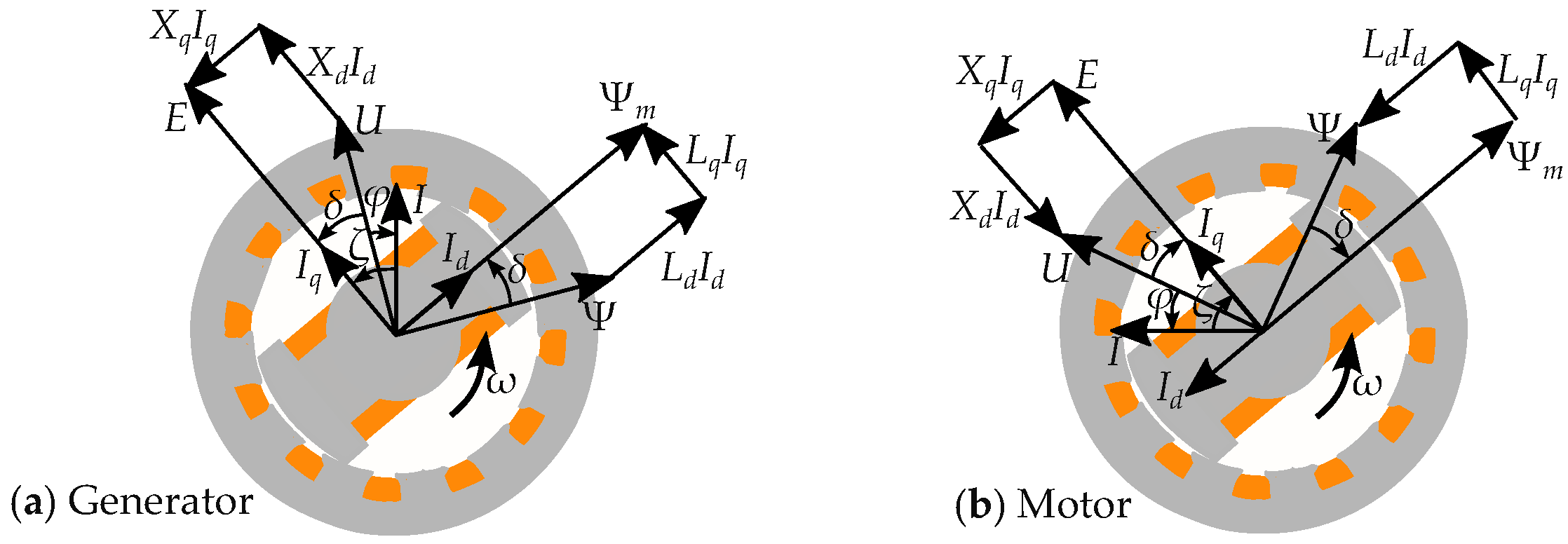
The load angle of a DC machine (as in Figure 3) can be compared that of a synchronous machine (as in Figure 4). The magnetic flux in the stator is angularly displaced in the rotor relative to the stator. This displacement in the geometry is equivalent to the load angle.
The flux of the armature reaction will act in two different directions relative to the rotor in a synchronous machine: both in the direct direction ( L d I d ), which is in parallel to the rotor pole, and in the quadrature direction ( L q I q ), which is perpendicular to the rotor pole. The magnetization flux ( Ψ m ) is instead defining the direct direction and then only acting in the direct direction. The resulting flux is then given by
Ψ d = Ψ m I d L d Ψ q = I q L q
This is shown in a machine in Figure 5, showing the magnetization flux ( Ψ m ) in the rotor direction and the resulting flux ( Ψ ) shifted by the load angle δ . The approach to account for salient poles is then to consider that the two components experience different inductance ( L d L q ) such that the relation between the current and the resulting flux depends on the load angle. A cylindrical rotor (without pole saliency) would instead be assumed to have the same inductance in each direction ( L d = L q ).
The induced terminal voltage, U in the d q -frame, is based on the magnetic flux Ψ but appears perpendicular to the magnetic flux, as in Figure 5 such that the voltage is
U d = U sin δ = I q X q U q = U cos δ = E I d X d
The two components are often illustrated by a two-circuit model, as in Figure 6, with one circuit based on the flux in the direct direction (d-direction) and another based on the flux in the quadrature direction (q-direction). Where each inductance relates to flux paths of the different angles.
The currents can be written as
I d = E U   cos δ X d = I sin ( ζ ) I q = U   sin δ X q = I cos ( ζ )
with the current angle, ζ , based on both the load angle, δ , and the phase angle, ϕ ( ζ = δ φ ). Note that both δ and φ can be with opposite signs and thus in opposite directions; this can make the subtraction resemble an addition for some cases.

2.1. Clark and Park Transform

Salient pole machines are often modeled based on the Clarke transform and the Park transform [33,34,35,36,37,38,39,40]. The Clarke transform represents the three alternating magnetic fields as one rotating magnetic field, where the rotation is described by two sine waves representing two directional axes in the stator reference frame. The Park transform represents d and q as stationary components (i.e., DC components), and represents the rotating magnetic flux in the rotor reference frame. The transforms can be seen as simplified approaches to symmetrical components [41,42].
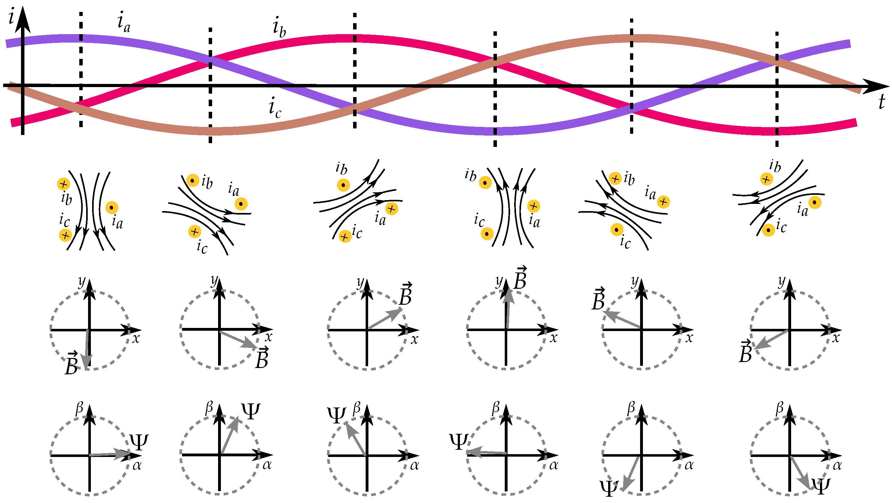
The three phases establish a rotating magnetic field in the stator reference frame such that the magnetic field rotates while the three phases have alternating current (as in Figure 7). This can be described by two sines in the α β -frame. So, the Clark transform is defined by the matrix
K c = 2 3 1 1 2 1 2 0 3 2 3 2
Note that this is a phasor model and not a vector model [39]. The magnetic flux linkage Ψ phasor will rotate in the same angular phase as the current phasor I. The magnetic flux density vector B is different and rotates in the actual geometry ( x y -plane) based on the direction of the induced magnetic flux density distribution.
Figure 7. The magnetic field induced by a three-phase system rotates in the geometry. The rotation is described in the α β -frame.
Energies 17 01015 g007
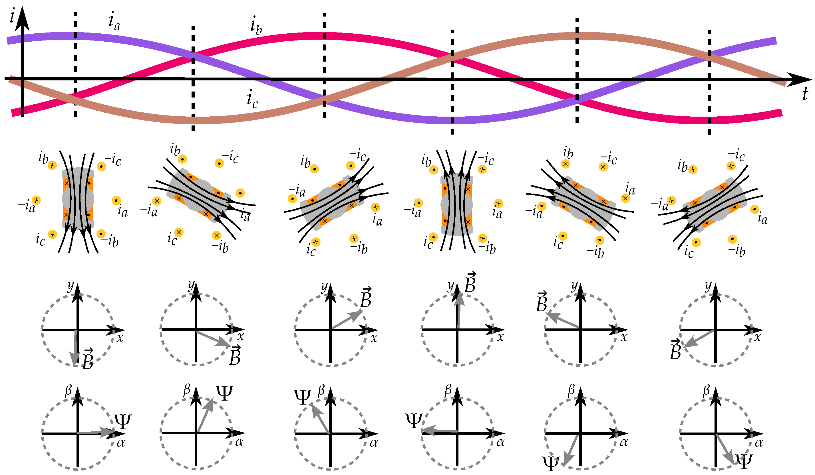
An adoption in a machine geometry would instead be based on the current of the stator windings and the rotating magnetic flux of the rotor. This is seen in Figure 8. Since the three phases in the stator are wound, they are illustrated with currents in both directions.
The three alternating phases are then modeled as a rotation in the stator reference frame by α β -components (with the different reference frames seen in Figure 9). The α -direction can be seen as being based on phase a, together with half of the components of phase b and c as a return conductor (which is the projection of b and c on the α -axis). The β -direction is based on the parts orthogonal to phase a, which are 3 / 2 of phase b and c (which is the projection of b and c on the β -axis).
The rotating magnetic field of the α β -components can be seen as a static magnetic field in d q -components of the rotor reference frame (with the different reference frames seen in Figure 9) such that the magnetic field is seen as rotating from the perspective of the stator but is static from the perspective of the rotor. This is because the magnetic field rotates together with the rotor.
K p = cos ( θ ) sin ( θ ) sin ( θ ) cos ( θ )
The idea of both the Clark transform and Park transform can be seen in Figure 10. The three phases are described by a rotation in the α β -frame. This rotation is then seen as two static components in the d q -frame such that the Park transform handles the field as “DC components” and the magnetic field is seen as “stationary” from the perspective of the rotor such that the magnetic field is stationary from the perspective of the rotor even if it is rotating from the perspective of the stator.
The load angle is seen as a phase shift in the stator reference frame (in the α β -frame). From the rotor’s perspective (in the d q -frame) we see the load angle as direction of the magnetic flux such that it remains as a fix direction.
A combined transform is written as
K = K p K c = cos ( θ ) sin ( θ ) sin ( θ ) cos ( θ ) K p 2 3 1 1 2 1 2 0 3 2 3 2 K c
The d q -components of the reactance can in many ways be seen as theoretical tools since they can be hard to measure in practice. Many different procedures have been developed for testing handling of this question [43,44,45].

2.2. Pole Saliency in a Three-Phase Machine

Consider a three-phase synchronous reluctance machine. The relation between three flux linkages and the three currents can be written by a matrix L , by
ψ a ψ b ψ c = L i a i b i c
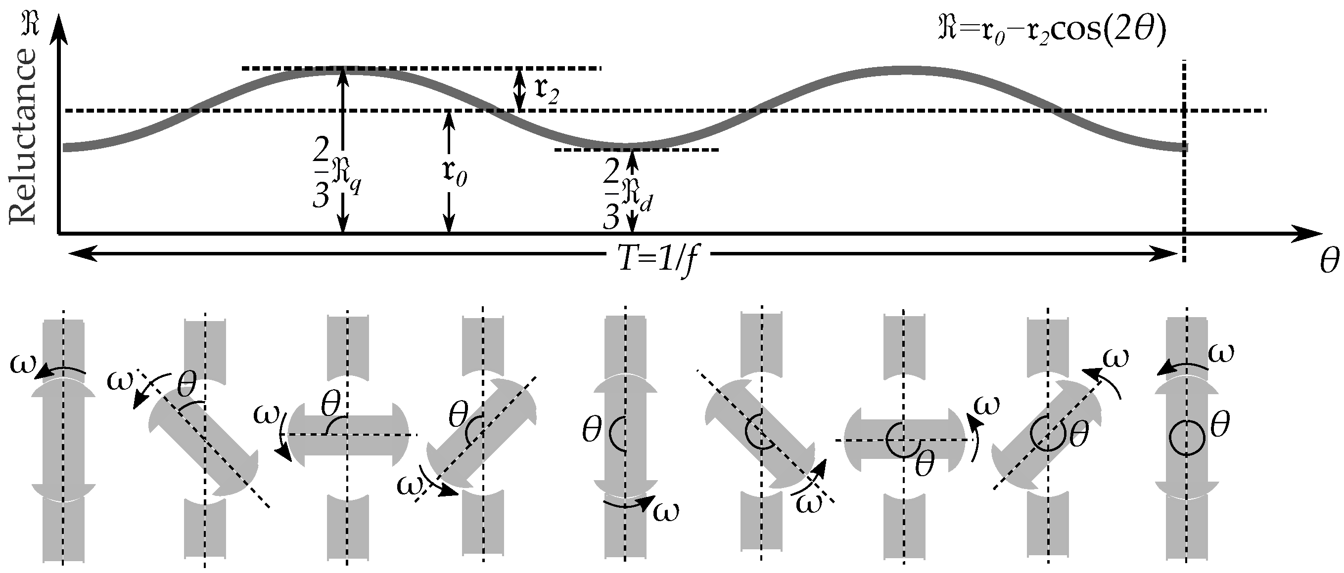
Variations in the inductance can be expressed as a function of the rotor angle such that the variation in inductance L ( θ ) is seen as a function of rotor position θ (in Figure 11). This function has twice the frequency as the rotation, since the saliency is symmetric on both poles. The inductance is high when the salient pole rotor is directed in the same direction as the magnetic flux, and this happens at both θ = 0 and θ = 180 . The inductance is low when the salient pole rotor is perpendicular to the flux path, and this happens at both θ = 90 and θ = 170 .
This inductance should not only consider the self-inductance of the three phases themselves; it should also include the mutual inductance between each winding [44,46,47]. An improved modeling would both consider the self-inductances and the mutual inductances of each phase, as in Figure 12. The three self-inductances are
L a a = l 0 + l 2 cos ( 2 θ ) L b b = l 0 + l 2 cos ( 2 ( θ 120 ) ) L c c = l 0 + l 2 cos ( 2 ( θ + 120 ) )
The mutual inductances are
M a b = M b a = l 0 2 + l 2 cos ( 2 ( θ 60 ) ) M a c = M c a = l 0 2 + l 2 cos ( 2 ( θ + 60 ) ) M b c = M c b = l 0 2 + l 2 cos ( 2 ( θ + 180 ) )
The relation between the three magnetic flux linkages and the three-phase currents are
ψ a ψ b ψ c = L a a M a b M a c M b a L b b M b c M c a M c b L c c i a i b i c
Transforming the three-phase system into the rotating d q -frame, we have
Ψ d q = Ψ d Ψ q = K ψ a ψ b ψ c = K L a a M a b M a c M b a L b b M b c M c a M c b L c c i a i b i c
Rewritten as an expression between the d q -frame flux and the d q -frame current
Ψ d Ψ q = K L a a M a b M a c M b a L b b M b c M c a M c b L c c K 1 I d I q
The inductance in the d q -frame is then
L d 0 0 L q = K L a a M a b M a c M b a L b b M b c M c a M c b L c c K 1
So, we have
ψ d q = ψ d ψ q = L d 0 0 L q I d I q
where this kind of matrix model is sometimes used as a more detailed description of the d q -components [48,49]. The matrix describes a mapping, as illustrated in Figure 13, which also includes a change in direction.
The relation between d q -frame inductances ( L d and L q ) and the three-phase inductance components ( l 0 and l 2 ) are given by
L d = 3 2 ( l 0 + l 2 ) L q = 3 2 ( l 0 l 2 )
The three-phase inductances relate to the d q -frame inductances by the ratio
L 0 = 2 3 l 0 L 2 = 2 3 l 2
where the d q -frame inductances are
L 0 = L d + L q 2 L 2 = L d L q 2
An adoption for a salient pole synchronous machine is similar but also includes the magnetic excitation with the field current i f and its mutual inductance M f . That is
ψ a ψ b ψ c = L i a i b i c + M f cos ( θ ) M f cos ( θ 120 ) M f cos ( θ + 120 ) i f
The magnetic flux Ψ is established by the armature current I and the excitation flux Ψ m . The magnetic flux can be seen as rotating together with the rotor where
Ψ d q = Ψ d Ψ q = L d 0 0 L q I d I q + Ψ m 0
This is equivalent to Ψ = L I + Ψ m , or more specifically, ψ d = Ψ m L d I d and ψ q = L q I q . This can be combined with the induced voltage by Lentz law as
U d q = d d t Ψ d q = U d U q = 0 ω ω 0 Ψ d Ψ q
such that the terminal voltage U is based on the flux of the stator teeth ψ by U = ω Ψ . This gives us the induced terminal voltage U as
U d q = U d U q = 0 ω L q ω L d 0 I d I q + 0 ω Ψ m
where the inductances are equivalent to the reactances X d = ω L d and X q = ω L q and the EMF as E = ω Ψ m , that is
U d q = U d U q = 0 X q X d 0 I d I q + 0 E

2.3. Phasor Interpretation of Vector Model

Both the d q -frame and phasor models of circuits share a feature in that they represent three-phase AC systems as single-phase DC models. A simplified approach to d q -components is to rewrite the vector as a phasor model. Such an approach to the d q -components is common and used in several books on the topic [47,50,51,52]. A phasor model of the current can be expressed based on the angle relative to the rotor flux, that is
I ¯ d q = I d + j I q
which usually is expressed by the real and the imaginary part based on the phase shift to the voltage as
I ¯ r i = I r + j I i
Circuit theory usually expresses it based on the electrical angle of the voltage, that is
θ v = ω t
The rotor reference frame (defined by the rotor flux) is lagging behind the voltage reference and is then given by
θ r = θ v ( 90 δ ) = ω t ( 90 δ )
This is then just a simple change in the angular reference, where the general phasor models is based on the voltage reference U as the angular reference (defined as 0 ). The d q -frame is instead expressing it based on the rotor flux (defined as 0 such that the EMF is at 90 ).

2.4. Power Flow in  d q -Frame

Generally, we have a complex power expressed by the real and imaginary parts of the current and the voltage
S ¯ = ( I r U r + I i U i ) P + j ( I r U i + I i U r ) Q
and equivalently for phasors expressed in the d q -frame it is written as
S ¯ = ( U q I q + U d I d ) P + j ( U q I d + U d I q ) Q
The power is based on the components with the same phase angle, while the reactive power is based on the two components that are phase shifted.
The active power is obtained by inserting the values of U d , U q , I d , and I q . For a salient pole machine, it is
P = U q I q + U d I d = U cos δ U sin δ X q + U sin δ E U cos δ X d
This is also written as
P = U sin δ X q U cos δ + E X d U sin δ U cos δ X d U sin δ
and more conveniently written as
P = U E X d sin δ + U 2 2 1 X q 1 X d sin 2 δ
The reactive power for a salient pole machine is
Q = U d I q + U q I d = U sin δ U sin δ X q + U cos δ E U cos δ X d
such that
Q = E U X d cos δ U 2 sin 2 δ X q U 2 cos 2 δ X d
and this can be rewritten as
Q = E U X d cos δ U 2 1 cos 2 δ X q U 2 1 + cos 2 δ X d
and also expressed as
Q = U E X d cos δ U 2 2 1 X q 1 X d cos 2 δ U 2 2 1 X q + 1 X d
This can also be performed only focusing on the power linked to saliency of the inductance, where we similarly only consider the reluctance torque part of the power as
P = U 2 2 1 X q 1 X d sin 2 δ
and the reactive part as
Q = U 2 2 1 X q 1 X d cos 2 δ U 2 2 1 X q + 1 X d

2.5. Matrix Representation of Phasor Models

Consider a phasor representation of an electrical circuit expressed by Ohm’s law with
U ¯ = Z ¯ I ¯
as phasor values U and I and a complex-valued impedance Z as
U ¯ = U r + j U i = ( R + j X ) · ( I r + j I i )
Adapted to vector and matrix notation, this is
U r i = U r U i = R X X R I r I i
Where the impedance ( Z ¯ = Z e j γ ) is written as
Z cos γ sin γ sin γ cos γ = R X X R

2.6. Voltage Reference Frame

Based on the matrix model of the circuit theory, we can integrate it with the matrix model of the rotor reference frame. We consider the voltage to be related to the rotor angle by
θ v = θ r + ( 90 δ )
The relation between the voltage reference frame and the rotor reference frame is shown in Figure 14. The voltage is placed with an angle 90° from the stator flux linkage, and the stator flux linkage is placed with an angle δ from the rotor flux linkage. The combined difference between the voltage and the rotor reference is then 90 δ .
A transformation of the angular reference from the rotor reference to the voltage reference can be performed by
U r U i = U 0 = cos ( 90 δ ) sin ( 90 δ ) sin ( 90 δ ) cos ( 90 δ ) U d U q
and for currents by
I r I i = cos ( 90 δ ) sin ( 90 δ ) sin ( 90 δ ) cos ( 90 δ ) I d I q
or also
I r I i = K v I d I q
with the transformation matrix
K v = cos ( 90 δ ) sin ( 90 δ ) sin ( 90 δ ) cos ( 90 δ )
This means that any rotating d q -frame vector can be handled as a phasor model in with the voltage reference frame.
A reactance in the d q -frame can be rewritten as an impedance in the voltage reference frame
Z r i = K v X d q K v 1
The rotation by the salient pole reactance ( X d X q ) matrix gives a direction that is not a 90 rotation.

3. Reactance Written in Two Parts

Consider the matrix form of the reactances in the d q -frame; this matrix can be separated into two parts and expressed as two terms by writing
0 X q X d 0 = X d + X q 2 X 0 0 1 1 0 + X d X q 2 X 2 0 1 1 0
where we can introduce the average reactance
X 0 = X d + X q 2
and the saliency reactance
X 2 = X d X q 2
such that it can be written in a simplified form:
X = X 0 0 1 1 0 + X 2 0 1 1 0
The first term is similar to a classical inductor, equivalent to a rotation by 90 . The first term is the related to the pole saliency, and a bit more special. It is not rotated 90 , and the matrix is instead describing a reflection in the line defined by q = d in the d q -frame.

Alternative Adoption for Salient Pole Synchronous Machines

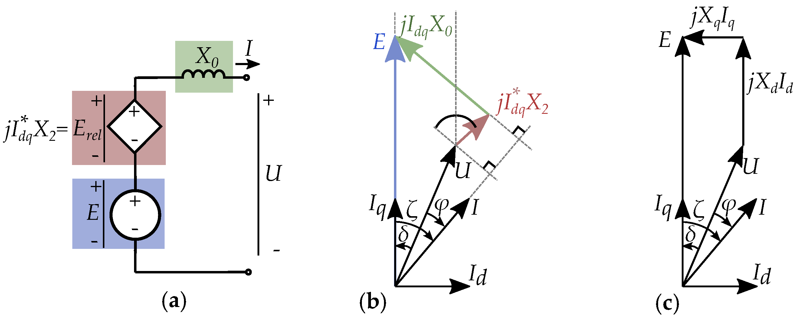
One model that includes the reluctance torque as a separate circuit element has been studied by Ahmed-Zaid and Oteafy [5]. This is illustrated in Figure 15, where the machine reactance is written as two series-connected parts [6] by using the average reactance X 0 = ω L 0 and the saliency reactance X 2 = ω L 2 . The average reactance acts similar to a typical inductance, while the saliency reactance is modeled based on a complex conjugate of the current. The saliency reactance is in the model seen given by
E ¯ r e l = j I ¯ d q X 2
where the star in I d q refers to the complex conjugate of the current when expressed as a phasor in the d q -frame. This can be seen in the phasor diagram in Figure 15b.
The terminal voltage of the machine is then written as sum of the three circuit elements, by
U ¯ = j X 0 I ¯ + E ¯ r e l + E ¯ = j X 0 I ¯ + j I ¯ d q X 2 + E ¯
The circuit model is then made as a sum of voltages (shown in Figure 15b) similar to classical d q -components (in Figure 15c).

4. Reluctance Models

4.1. Three-Phase Reluctance Model

Consider a reluctance machine; a simplified model of the reluctance describes that the reluctance depends on the rotor angle, as illustrated in Figure 16, such that the period of the reluctance is two times the period of the electrical alternation. The reluctance is lower when the salient pole rotor is directed in the same direction as the magnetic flux, and this happens both at θ = 0 and θ = 180 . The reluctance is higher when the salient pole rotor is perpendicular to the flux path, and this happens both at θ = 90 and θ = 170 .
A single-phase equivalent is however a very simplified representation of a machine. When we consider a full three-phase synchronous machine, we will instead have one reluctance for each phase such that each phase has an own contribution to the reluctance and each phase has to consider mutual dependence on the other phases. Such a system of three-phase currents for a reluctance system is seen in Figure 17. This is such that the relation between the stator current and the magnetic flux can be described as a matrix similar to the case with the inductances. That is
N s I a N s I b N s I c = R a a R a b R a c R b a R b b R b c R c a R c b R c c Φ a Φ b Φ c
The reluctances equivalent to the self-inductance are given by the functions
R a a = r 0 + r 2 cos ( 2 θ ) R b b = r 0 + r 2 cos ( 2 ( θ 120 ) ) R c c = r 0 + r 2 cos ( 2 ( θ + 120 ) )
The reluctances equivalent to the mutual inductances are
R a b = R b a = r 0 2 + r 2 cos ( 2 ( θ 60 ) ) R a c = R c a = r 0 2 + r 2 cos ( 2 ( θ + 60 ) ) R b c = R c b = r 0 2 + r 2 cos ( 2 ( θ + 180 ) )
The system can be expressed in the d q -frame ( R d < R q for L d > L q ) as
N s I d N s I q = R d 0 0 R q Φ d Φ q + N r I f 0
and then rewritten as
N s I d N s I q = ( R 0 1 0 0 1 + R 2 1 0 0 1 ) Φ d Φ q + N r I f 0
with the reluctance of the two parts as R 0 = ( R q + R d ) / 2 and R 2 = ( R q R d ) / 2 .
The expression can be related to electrical circuits by replacing the magnetic flux with
Φ d q = U d q N s ω 0 1 1 0
such that the expression can be written as a relation between voltage and current in the same form as an susceptance, that is
I d I q = ( R 0 N s 2 ω 0 1 1 0 + R 0 N s 2 ω 0 1 1 0 ) U d U q + N r N s I f 0

4.2. Inverse Expression of Reactances

The reactances in the d q -frame, expressed in matrix form, can be used to find an inverse expression
0 X q X d 0 1 = 1 X q X d 0 X q X d 0 = 0 1 X d 1 X q 0
Rewritten as two terms, one for average contribution and one for saliency, the result is
1 2 1 X q + 1 X d Y 0 0 1 1 0 + 1 2 1 X q 1 X d Y 2 0 1 1 0
The first term is expressing a rotation of 90 degrees (similar to common reactances), while the second term is a reflection in the line defined by d = q (which is the susceptance dependent on the load angle).
By introducing the saliency susceptance
Y 2 = 1 2 1 X q 1 X d
and the average susceptance
Y 0 = 1 2 1 X q + 1 X d
we write it as
0 1 X d 1 X q 0 = Y 0 0 1 1 0 + Y 2 0 1 1 0

4.3. Simplified One-Phase Equivalent

Reluctance circuits have an advantage in that they easily relate to Ampere’s law. So, starting from Ampere’s law (in a simplified approach of Maxwell’s equations), we have
× B / μ = J
This can be written in an integral form as
B / μ · d l = J d S
which consists of two terms: the ampere contour integral and its enclosed current density.
The ampere contour integral of the flux density B can be described by the magnetic flux ϕ and the reluctance of the geometry R , as
B / μ · d l = ϕ R
The enclosed current density J consists of both the contribution from the stator armature and the rotor field current
J d S = N s I + N r I f
with N s as the stator winding turns, I as the stator armature current, N r as the rotor winding turns, and I f as the rotor field current. The complete reluctance circuit with both the current MMF and the reluctance is then
ϕ R = N s I + N r I f
In an electrical system, we may have a voltage with a frequency, whereas in a reluctance circuit we have a related magnetic flux with a frequency. A voltage source in an electric system can then be equivalent in many contexts to a magnetic flux source in a magnetic system [53,54,55]. If we consider a connection to a power system (a strong grid), we can assume that the transmission system is providing a stable voltage magnitude U and a stable frequency f. Consequently, we can also assume a stable rotating magnetic flux linkage given by Ψ = U / ( 2 π f ) . Another case exists for applications where the machine is connected to a voltage source converter. These often function with control based on the magnetic flux such that the voltage is modulated for a desired rotating flux.
A Norton equivalent can easily be related to an equivalent reluctance circuit, as seen in Figure 18. The current source of the electrical circuit is then equivalent to the MMF of the reluctance circuit, and the inductance is equivalent to the reluctance. The main difference is that electrical circuits have voltages, while reluctance circuits have magnetic fluxes, which are related by U = j ω Ψ .
A difference is that elements connected in parallel from an electrical circuit become elements connected in series in a magnetic circuit, since a sum of currents is connected in parallel in electrical circuits while they are connected in series in a reluctance network. This is useful to consider when comparing an electrical Norton equivalent with an equivalent reluctance circuit (as in Figure 18) such that the equivalent magnetic circuit resembles the look of a Thevenin equivalent. An actual electric Thevenin equivalent is instead based on a sum of voltages, which is a series connection in an electrical circuit. This is instead equivalent to a parallel connected magnetic flux in a reluctance network (as seen in Figure 18).
It is useful to keep in mind the relation between electrical circuits and magnetic circuits when modeling electrical machines (see illustration in Figure 19). A Norton equivalent model fits very well to a reluctance circuit model.

5. Current Equivalent Models

Simple Norton equivalents are well known from most basic course literature in circuit analysis. Instead of writing the inductance in series with the EMF, the inductance is put in parallel with an equivalent current source (shown in Figure 20).
The EMF can be written as a phasor in the rectangular form as
E ¯ = E cos ( δ ) + j E sin ( δ )
such that the Norton equivalent current can be found by
I ¯ N = E ¯ Z ¯ = E cos ( δ ) + j E sin ( δ ) j X = E sin ( δ ) X j E cos ( δ ) X
The equivalent current source (see Figure 20), based on an EMF of a synchronous machine, is
I ¯ N = E ¯ j X = E X sin δ + j E X cos δ
such that it is angularly located based on the load angle, as
I ¯ N = | I ¯ N | ( 90 + δ )
In many contexts, it is more convenient to rewrite it in the opposite form (as seen in Figure 21), which is then written as
I ¯ e = I ¯ N
where the phase angle of the current source is
I ¯ e = | I ¯ e | ( 90 δ )
The load angle relates to the phase shift between the current and the magnetic flux, shown in Figure 22. This affects the phase angle of the current source I e , as in Figure 23. This is also the angular phase shift between the voltage phasor and the current phasor, as in Figure 24.
The current of the equivalent be split in a real and an imaginary part can be
I ¯ = I r + j I i = E X sin δ + j E X cos δ U X
which can be seen as a sum the two equivalent components
I ¯ = I ¯ x + I ¯ e
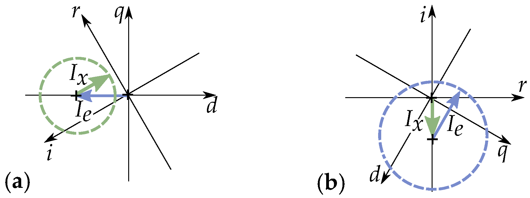
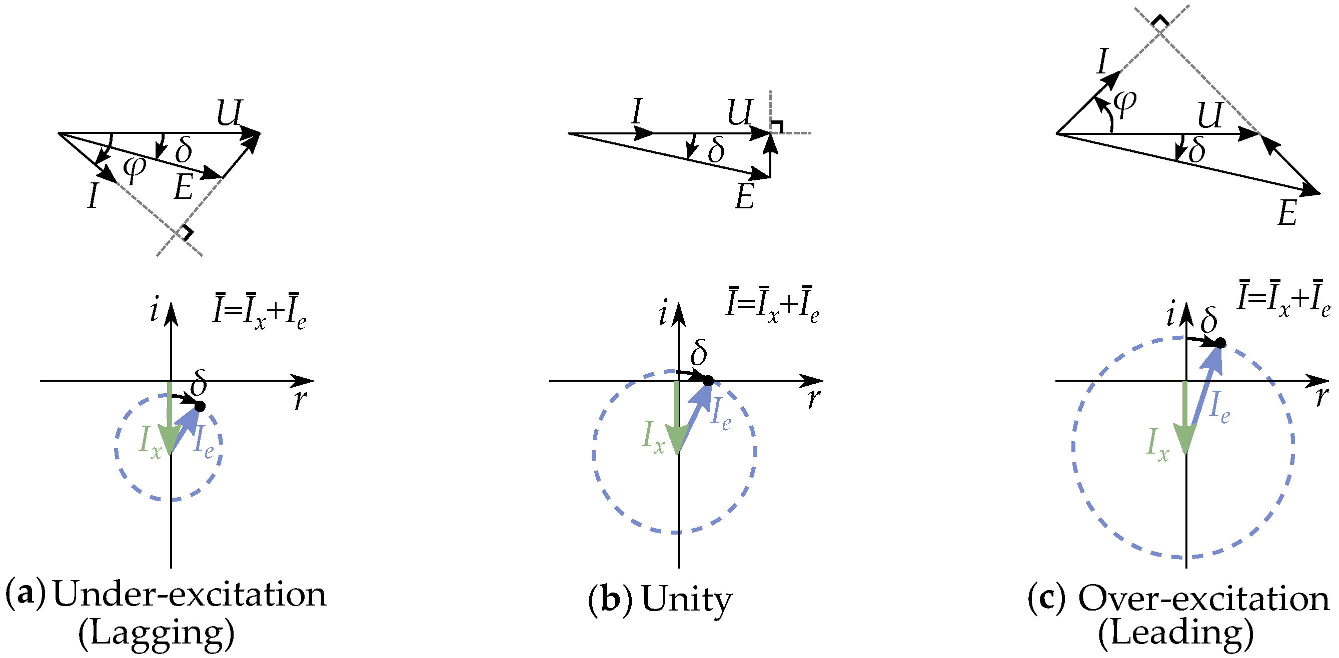
It can either be seen as an excitation current with an angular dependent magnetization current in the rotor reference frame ( d q -plane), as in Figure 25a or as a magnetization current with an excitation current dependent on the load angle in the voltage reference frame ( r i -plane), as seen in Figure 25b.
The series-connected inductor of a Thevenin equivalent is replaced by a shunt connected inductor. The current of the inductance is
I ¯ x = j U X
The inductance is conveniently written as a susceptance Y ¯ = j B 0 , that is, a current with a 90 phase shift, as
I ¯ x = | I ¯ x | 90
A current-equivalent model of a synchronous machine (with non-salient poles) can be described by a phasor diagram, as in Figure 26, expressed as a combination of the current of the equivalent inductor and the equivalent current source. The current of the inductor is placed 90 relative to the voltage, while the angle of the current source depends on the load angle.

5.1. Field Weakening

In the reluctance circuit, we see that magnetic flux is dependent on the phase angle between the rotor field current and the rotor armature current, with the rotor field current based on the d-direction ( 90 + δ ) and the stator armature with the current angle ( δ ϕ ). Field weakening is then based on the idea that the phase shift is decreased such that the magnetic flux is made low.
The reluctance circuit of the system is seen in Figure 27 and given by
N s I ¯ = R Φ ¯ + N r I ¯ f
A Norton equivalent easily describes this (Figure 28) by rewriting it as
I ¯ = 1 N s R Φ ¯ + N r N s I ¯ f = I ¯ m + I ¯ e
with the magnetization current ( I m = I x ) based on the magnetic flux Φ .
Field weakening is based on considering the constraints of the maximum current and the maximum voltage. In addition to the constraints in the maximum current, we also have constraints from the maximum voltage, which can also be expressed as a limitation of the current phasor, with the constraints as follows:
| I ¯ |   | I ¯ m a x | | I ¯ |   | I ¯ e + I ¯ m |   =   | I ¯ e + Y ¯ U ¯ m a x |
The two limits of the current can be seen in Figure 29, both in the rotor reference frame ( d q -plane) and the voltage reference frame ( r i -plane).
A Norton equivalent model easily relates to the constraints (as seen in Figure 30), so each current in the current-equivalent model is used to describe the constraints. The limit of the magnetizing current I m is linked to the magnetic flux and then affected by the maximum voltage limit. This current then sets the boundary for field weakening. This current is frequency dependent since the susceptance decreases with increasing frequency. That is
Y = 1 ω L 1 ω I m = Y U = U ω L 1 ω
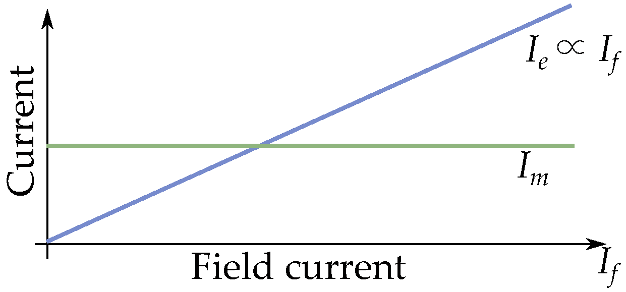
The magnetization current decreases with an increased frequency, while the current of the current source is constant for a constant field current (seen in Figure 31).

5.2. Comparison to Transformer Models

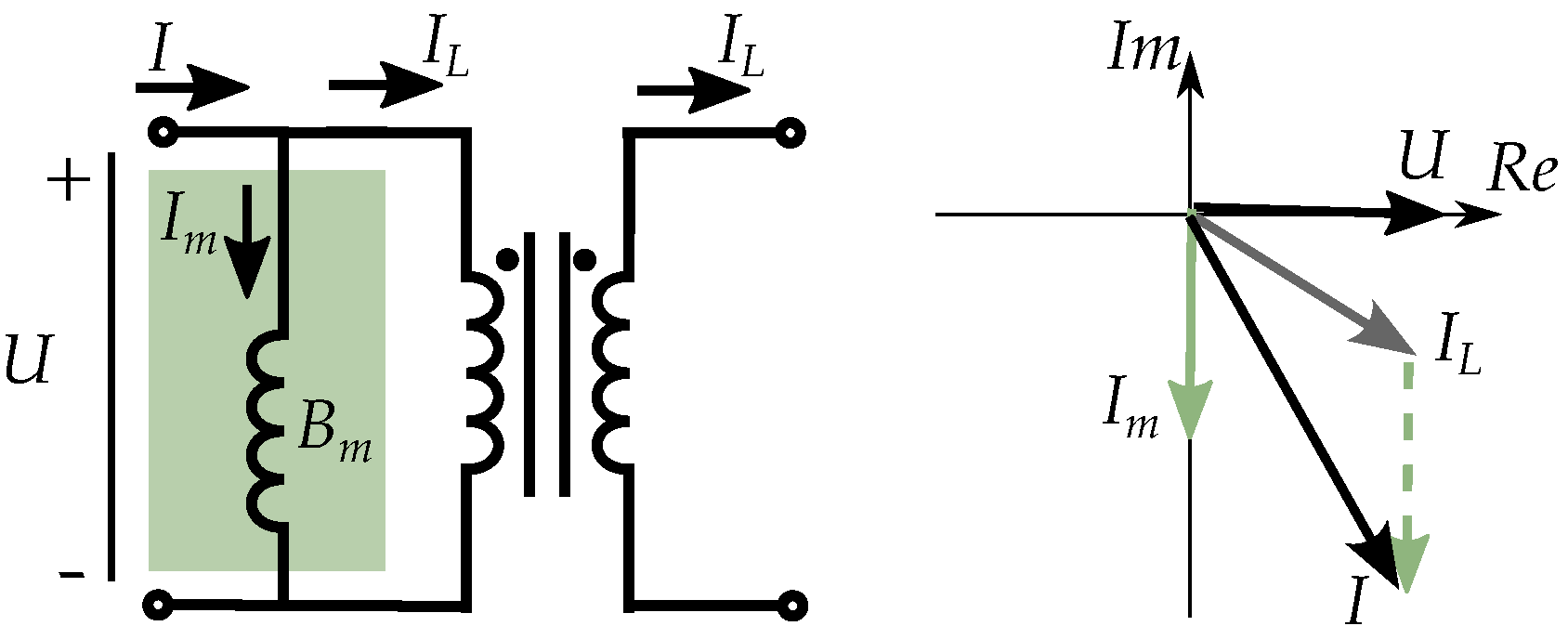
A Norton equivalent of a synchronous machine will be more similar to transformer models. One similarity is the treatment of the magnetization as a shunt inductance. This magnetization shunt branch is in parallel with the load current (see Figure 32, with I m as I x ). Transformer models also handle the magnetization branch as a shunt-connected inductance, which is directly relatable to Norton equivalent circuit models.
The rotor field current is handled as an equivalent current on the armature winding such that the rotor acts as a secondary side current source but transformed over to the stator primary side.
The rotating magnetic flux of the field windings will appear as an alternating flux from the perspective of the three-phases in the stator armature windings. The rotating flux will then appear similar to an alternating secondary side such that the field current acts similar to a secondary side current.
The current source I ¯ e has a magnitude set by the magnitude of the field current and a phase angle based on the load angle such that the circuit equivalent of the current source
I ¯ e = N r N s I ¯ f
which is similar to a transformed secondary side current of a transformer.

5.3. Comparison to Induction Motor Models

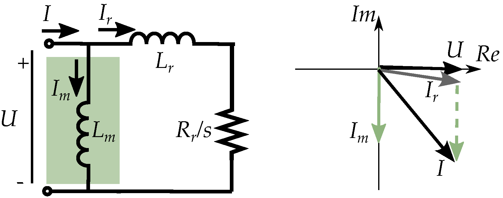
Induction motor models are often based on transformer models. The induced rotor field current is handled as a secondary side and rewritten for the stator side as an equivalent on the primary side (see Figure 33).
A Norton equivalent model of a synchronous machine is then following the same analogy of induction machine models, where the magnetization inductance is handled as a shunt branch and the rotor current is handled as an equivalent on the stator side.
The magnetic field of the rotor is rotating based on a combination of the mechanical angular speed of the rotor and the angular frequency of the alternating rotor current. This is so that the magnetic field rotates synchronously while the mechanical rotation is slipping behind asynchronously, illustrating the similarity between induction machines and synchronous machines.

5.4. Equivalent Excitation Current

The rotating field current appears as a transformed alternating current source, that is
I ¯ e = N r N s I ¯ f
with the complete stator current by
I ¯ = Φ ¯ R ¯ N s + N r N s I ¯ f
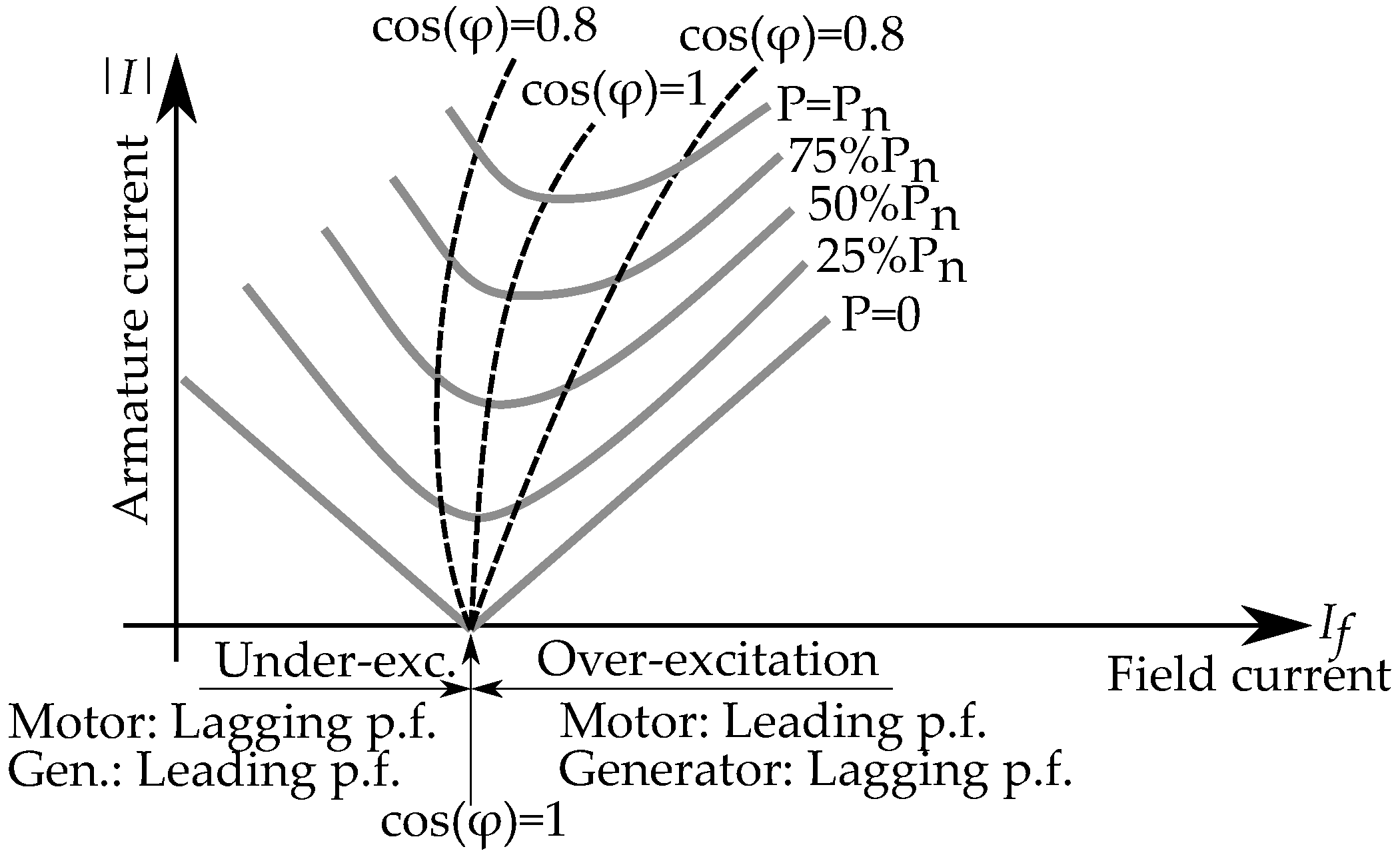
This model focuses on the currents and can then be related to how synchronous machines behave depending on the power load and the excitation of the field current. This is often studied by curves of the armature current as a function of the field current (often referred to as V-curves), as shown in Figure 34. The field current controls the magnitude of the equivalent current source, while the power load sets the angle (as the load angle). This then acts in parallel to the element that represents the inductance so that a low-field current is equivalent to a case where it only becomes an inductance. The current-equivalent model consists of two parts: one magnetization current, and one current of the current source.
I ¯ = I ¯ x + I ¯ e
The imaginary parts of the current (i.e., the out-of-phase components) will be opposed to each other. Since the two components are opposed, they contribute differently to the phase angle so that they can cancel each other when they have the same magnitude.
The magnetization current is equivalent inductor, while the current source is dependent on the field current. The two components can be compared, as seen in Figure 35, which shows how magnetization current dominates for low-field currents, and the current source dominates for high-field currents.
This current-based approach can be compared to classical phasors of Thevenin equivalents, as performed in Figure 36. The Norton equivalent is consisting of a sum of currents, as I e , I x , and I. The magnitude of the current source ( | I ¯ e | ) is set by the magnitude of the field current, and its angle is based on the load angle. The imaginary part of the armature current is set by the sum of the two other imaginary parts, while the real part of the armature current is set by the real part of the current source. Here, it could be worthwhile to note that (the imaginary part of) the current source has an opposing phase angle relative to the inductance and is similar to a capacitive current.
Another feature is also that the equivalent current source I e is not frequency-dependent, as the case for the EMF E. This simplifies the representation of the excitation for various speed drives.

5.5. Current Equivalent of Permanent Magnets

Permanent magnets may seem very different from field currents in the way that they cannot obviously be treated similarly to the current of field windings. However, permanent magnets are still also easily modeled by equivalent currents based on reluctance circuit MMFs. So, permanent magnets can be integrated in both reluctance circuits and electrical circuit models [56,57,58,59,60,61].
Consider that a magnetization can be represented by an equivalent current density based on ampere’s law such that a remnant magnetization M r (with a relative recoil permeability μ r e c ) of a permanent magnet would be equivalent to a current density as
J m = × M r / μ r e c
The adoption as an MMF in a reluctance circuit based on the magnet length is then written as
F = M r μ r e c l
and it can be adopted as an equivalent current in the electrical stator circuit, based on the number of armature windings of the stator, by writing
I e q = 1 N s M r μ r e c l
This part is linked to the excitation torque of a permanent magnet based rotor. There is also an impact by the permeability ( μ r e c ) of the magnet, so that it could effect the rotor pole saliency, and contribute to the reluctance torque. Where an internal permanent magnet in the rotor could decrease the inductance for the magnetic flux in the d-direction.

6. Salient Pole Machine Modeling

A circuit model can be introduced that considers the rotor pole saliency by considering the power of salient pole synchronous machines. This section will describe such a model, by starting from the active and reactive power of both the excitation torque and the reluctance torque. The active power is
P = U E X d sin δ P e m f + U 2 2 1 X q 1 X d sin 2 δ P r e l
and the reactive power is
Q = U E X d cos δ Q e m f U 2 2 1 X q 1 X d cos 2 δ Q r e l U 2 2 1 X q + 1 X d Q x
The torque is easily related to the active power by
τ = P ω m e k = P 2 ω / p
such that the torque consists of both the excitation torque and the reluctance torque, which are the components from the excitation system and the reluctance tor que.
τ = 3 p 2 U E ω 2 L d sin δ + U 2 2 ω 2 1 L q 1 L d sin 2 δ
One approach to the torque is to write it similar to a Lorentz force based on the d q -components [49,62]. The torque is then
τ = 3 p 2 ψ d I q ψ q I d
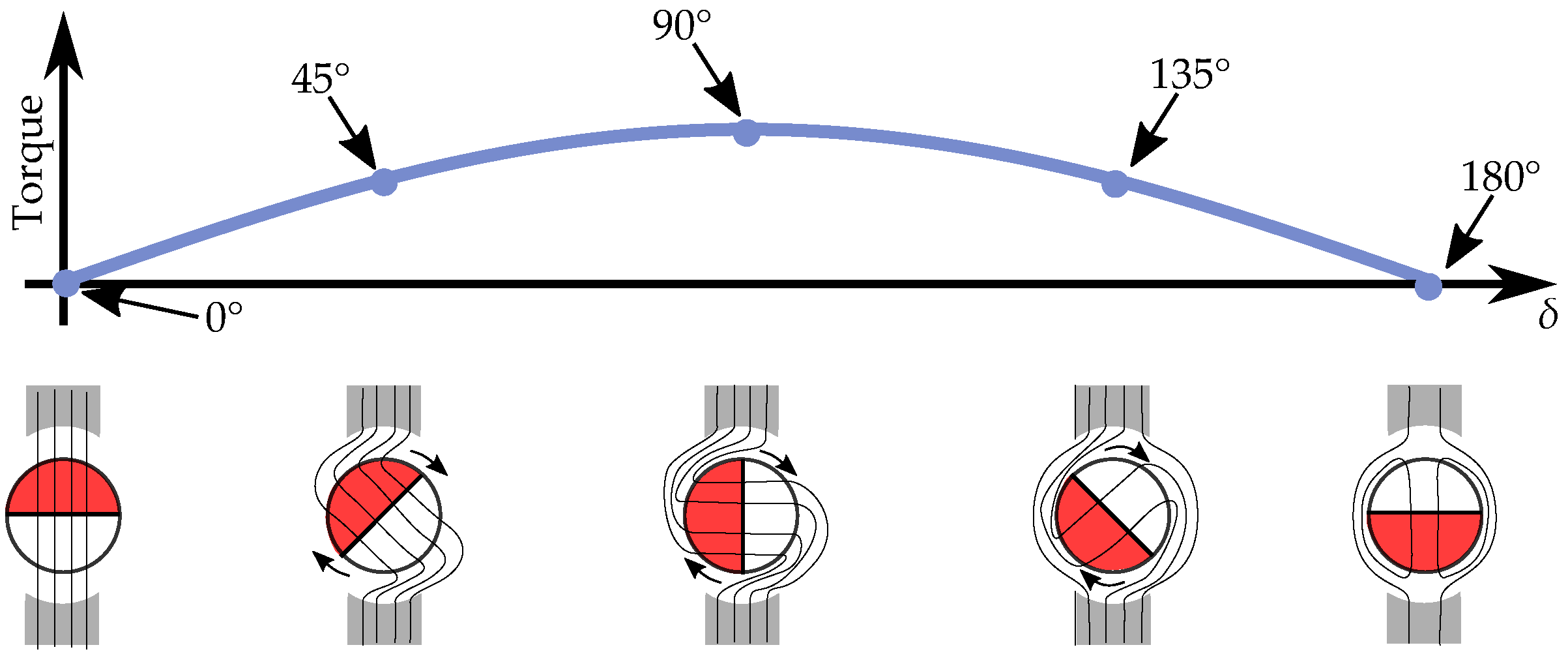
The torque depends on the load angle δ , as shown in Figure 37. Illustrating the excitation torque of a magnetized rotor, with the maximum torque at an orthogonal load angle at δ = 90 .
The angular dependence is different for the reluctance torque, with the maximum torque at the load angle δ = 45 , as in Figure 38. It is also contributing with different directions above and below the load angle δ = 90 .
The complete torque will be a combination of both the excitation torque and the reluctance torque, as shown in Figure 39, where the excitation torque is established by field windings or permanent magnets and the reluctance torque is caused by the pole saliency. There are also machines with a reverse saliency, where the contribution of the reluctance torque is the opposite of the common reluctance torque, as seen in Figure 40. The pole saliency in classical field wound synchrnous machines use to have an increased saliency in the direction of the poles ( L d > L q ), due to the high permeability of the the steel. Permament magnets based rotors could instead have the saliency in the opposite direction ( L d < L q ), due to the low permeability of the permanent magnets. But the saliency is dependent on the rotor design, and modifications to the angular direction of the magnetic flux paths in the rotor could instead give an angular displaced or reverse saliency [7,8,9,10].

Current-Equivalent Model for Salient Pole Machines

The current of a salient pole synchronous machine can be seen based on the active and reactive power.
I ¯ = I r + j I i = P j Q U
with the real part of the current equivalent to the active power
I r = E X d sin δ + U 2 1 X q 1 X d sin 2 δ
and the imaginary part of the current equivalent to the reactive power
I i = E X d cos δ U 2 1 X q 1 X d cos 2 δ U 2 1 X q + 1 X d
This current could be related to circuit elements. An equivalent circuit model for a salient pole synchronous machine is seen in Figure 41. Here, the pole saliency can be handled as a special separate current source, as in Figure 41a. Then, similar to the method in Section 3.1 by Ahmed-Zaid and Oteafy [5]. But a version with an equivalent current source can instead be rewritten even further. This can alternatively be seen as a susceptance model, as in Figure 41b, where an equivalent resistance represents the reluctance torque.
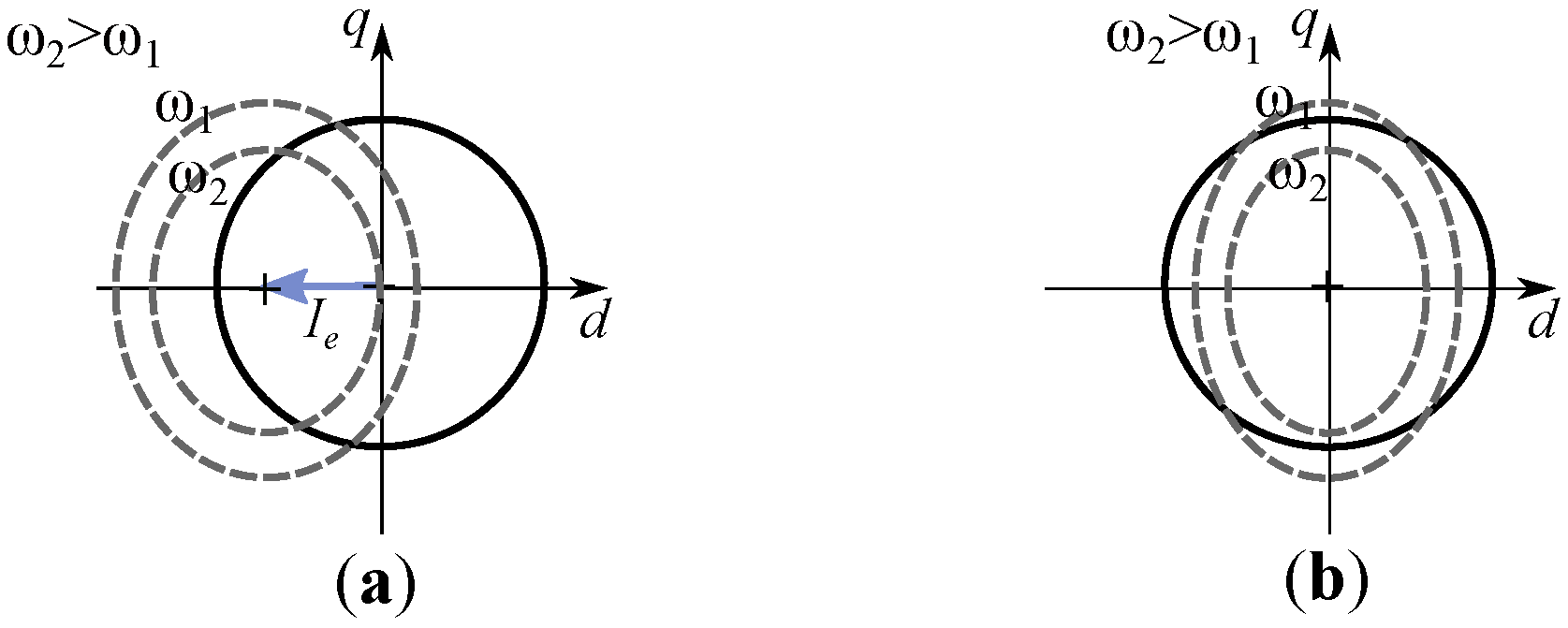
The magnetization current ( I ¯ m = I ¯ x + I ¯ r e l ) is dependent on the direction in the d q -plane. This can be illustrated for a salient pole machine in Figure 42a and reluctance machine in Figure 42b, showing the feasible magnetization current as region in the d q -plane.
Current source equivalent with two current sources (one classical and one for the saliency), together with an inductance, is
I ¯ = I ¯ x + I ¯ r e l + I ¯ e
The classical current source (representing the excitation current) is
I ¯ e = E X d sin δ + j E X d cos δ
The current of the equivalent (average) reactance is
I ¯ x = j U 2 1 X q + 1 X d
the equivalent current of the reluctance torque is
I ¯ r e l = U 2 1 X q 1 X d sin 2 δ j U 2 1 X q 1 X d cos 2 δ
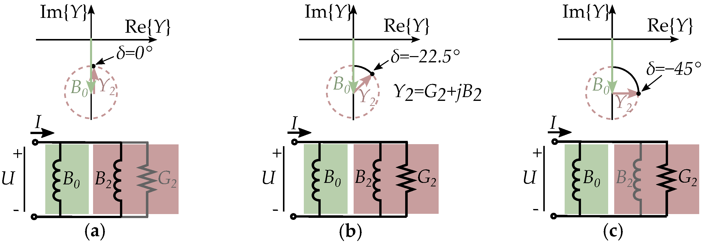
The current of the average susceptance and the saliency susceptance are illustrated in Figure 43. The average susceptance is always 90 from the voltage. The saliency susceptance is different and instead reflected in the line q = d , equivalent to a rotation of 90 2 δ . Its dependence on the load angle is shown in Figure 44, showing the saliency susceptance for δ = 0 (Figure 44a) and δ = 45 (Figure 44c).
The active and reactive power of the reluctance torque can be seen as a resistance in parallel with an inductance, where the current is dependent on the load angle, similar to the equivalent of the EMF, with a difference in that the reluctance torque is modeled by passive circuit component in contrast to EMF, which is seen as an active circuit component.
The magnetization current in a salient pole machine is given by two terms, with one for the average susceptance and another for the salient susceptance. That is
I ¯ = I ¯ x + I ¯ r e l
The current is angularly dependent based on the load angle δ such that the current is given by
I ¯ = U ¯ | Y ¯ 0 | e j ( 90 ) + U ¯ | Y ¯ 2 | e j ( 90 + 2 δ )
So, the magnetization current is defining an ellipse in the d q -plane via the pole saliency. The radius is not just set by the angularly independent I x ; it is also set by the angularly dependent I r e l , which is based on the load angle. The current is decreased in the d-direction (for L d > L q ) and increased in the q-direction (for L d > L q ).
The angular dependence can also be expressed in the voltage reference frame ( r i -plane) instead of the rotor reference frame ( d q -plane).
The susceptance is then written as
Y ¯ = Y ¯ 0 + Y ¯ 2 =   | Y ¯ 0 | e j ( 90 ) + | Y ¯ 2 | e j ( 90 + 2 δ )
such that the complex power is
S ¯ = U ¯ ( U ¯ Y ¯ 0 + U Y ¯ 2 + I ¯ e )
The active power is then given by
P = U 2 G 2 + U I e sin ( 2 δ )
and the reactive power is given by
Q = U 2 B 0 + U 2 B 2 + U I e cos ( 2 δ )

7. Reluctance Machine Model

The model of the reluctance torque within the circuit model is handled by a complex susceptance. Complex susceptance models (inverse complex inductance models) have been used in other previous studies to model the impact of salient poles [63,64,65]. Similarly, they have been used in models of nonlinear magnetization to include the impact of saturation [66].
The locus of the magnetization current in a reluctance machine is shown in Figure 45. An increased saliency can be used to improve the power factor [67,68,69].
The magnetization current expressed by two currents can be seen as two components (see Figure 46): one component is the same for all load angles while the other depends on the load angle.

7.1. The Complex Saliency Susceptance Model

The equivalent susceptance of the pole saliency is given by
Y ¯ 2 = 1 2 1 X q 1 X d sin 2 δ j 1 2 1 X q 1 X d cos 2 δ
such that it is a complex number in a Cartesian form by
Y ¯ 2 = G 2 + j B 2
The susceptance have two components, which depend on the magnitude of | Y ¯ 2 | and the load angle δ
G 2 = 1 2 1 X q 1 X d sin 2 δ = | Y ¯ 2 | sin ( 2 δ )
B 2 = 1 2 1 X q 1 X d cos 2 δ = | Y ¯ 2 | cos ( 2 δ )
(note that this refers to the circuit component B 2 and not to a flux density).
Y ¯ 2 = 1 2 1 X q 1 X d sin ( 2 δ ) + j cos ( 2 δ )
It can also be written in polar coordinates as magnitude
| Y ¯ 2 | = 1 2 1 X q 1 X d
with the angle based on the load angle
( Y ¯ 2 ) = 90 + 2 δ
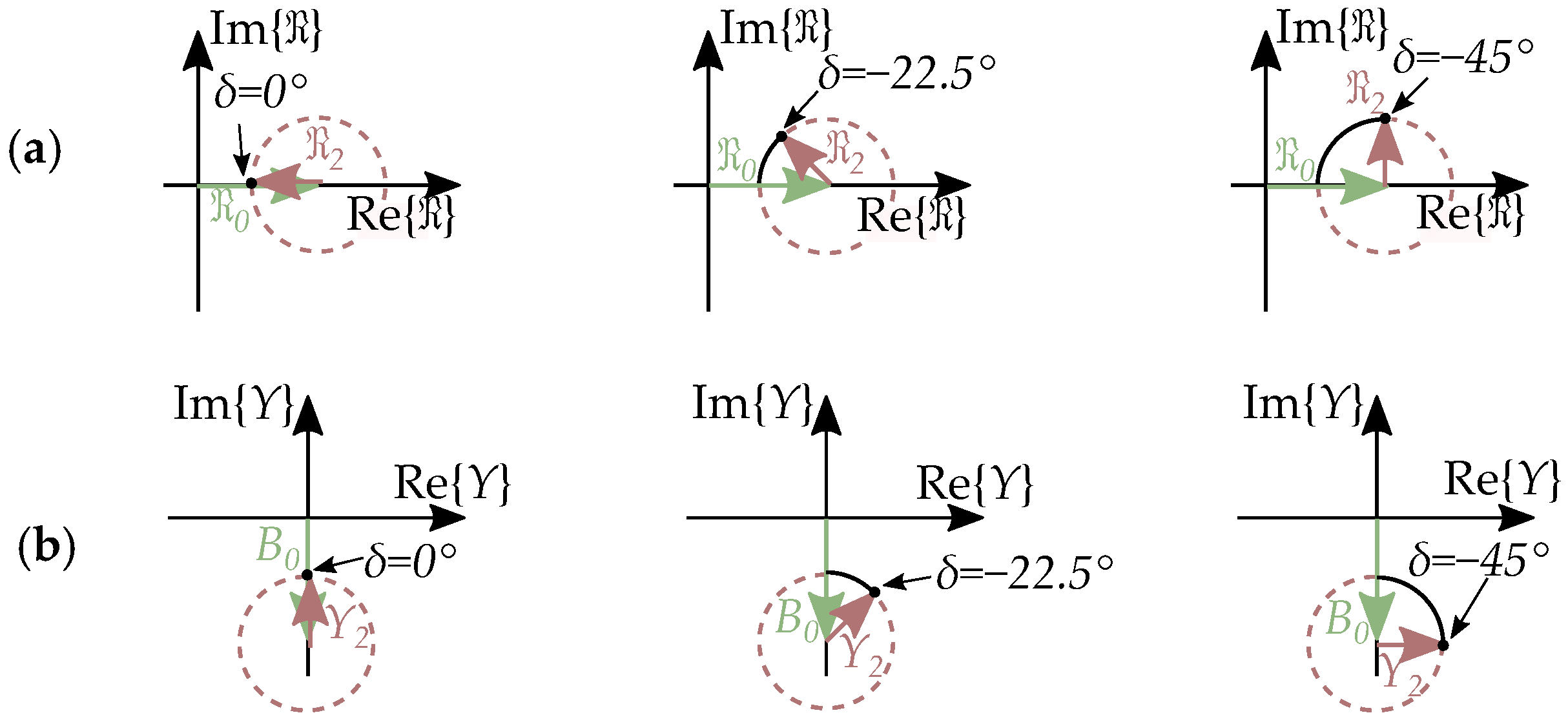
The equivalent susceptance of the pole saliency (i.e., the reluctance torque) is dependent on the load angle, as illustrated in Figure 47. It is purely imaginary at δ = 0 and purely real at δ = 45 . All values in between are described as combinations of real and imaginary components.
The plots of the susceptance share similarities with admittance plots for Nyquist plots. However, there is a notable difference: in this case, both the susceptance and conductance are frequency-dependent, while classical conductance is not frequency-dependent. This is because this conductance ( G 2 ) is not a real ohmic resistance, and instead related to an imaginary component of the magnetic flux. Then, it instead acts as an imaginary part of the inductance or an imaginary part of the reluctance.

7.2. Imaginary Reluctance Compared to Resistance

A salient pole rotor can be described by a complex reluctance when it is adopted in a phasor model, with the reluctance dependent on the load angle as in Figure 48. This is equivalent to the load angle-dependent susceptance, as seen in Figure 48, where the imaginary part of the complex reluctance is a real-valued part of the susceptance.
The current of an inductor is usually in phase with the flux, and thus phase shifted from the voltage. A complex-valued reluctance changes this relation and introduces a phase shift between the magnetic flux and the current such that the current and the magnetic flux are angularly displaced relative to each other.
A clear difference between common resistances and imaginary reluctances is frequency dependency: resistors are not frequency-dependent, but imaginary reluctances are equivalent to a frequency-dependent conductance.

7.3. Comparison to Hysteresis Models

The model of the reluctance torque is in many ways resembling the modeling of iron losses, where the losses are equivalent to a sum of currents and each term is based on a specific frequency dependency.
Here, the term “frequency dependency” is used a bit different in iron loss modeling as compared to circuit theory. This is because iron losses used to be analyzed as energy loss per period based on the magnetic flux density while in circuit theory, the frequency dependency is different, with losses expressed as a power and with resistance seen as a frequency-independent circuit element. Impedances are then instead frequency dependent.
Iron losses can, at the simplest level, be split in to hysteresis losses and eddy current losses, following the simplest form of Steinmetz equation [70,71,72] with the average power loss per period expressed by
P = k h B β f V + k e B 2 f 2 V
This is calculated for a flux density B, a volume V, the parameters k h , k e , and β with hysteresis losses P h as the term proportional to the frequency, as eddy current losses, and P e as the term dependent on the square of the frequency. It can be replaced by an expression based on the magnetic flux (instead of the flux density) by using modified parameters and then as
P = P h + P e = K h Φ β f + K e Φ 2 f 2
For simplicity, we can assume β = 2 and then have
P = P h + P e = K h Φ 2 f + K e Φ 2 f 2
To fit better with circuit theory, it can then be expressed as a function of the voltage instead of the magnetic flux with a small modification of the parameters such that we have
P = P h + P e = κ h f U 2 + κ e U 2
with the equivalent hysteresis conductance G h = κ h / f and the equivalent eddy current conductance G e = κ e such that it can be adopted for circuit components with
P l o s s = G h U 2 + G e U 2
The relation between magnetic field strength H and the magnetic flux density B can at the most basic level be described by a linear relation based on the reluctivity ν as the inverse of μ .
H = ν B
When including hysteresis losses in the magnetization of the iron, the model can be rewritten with a complex reluctivity (similar to complex permeability models [73,74,75]) as
H ¯ = ν ¯ B ¯ = ( ν + j ν ) B ¯
When a third term is added based on the induced eddy currents considering conductivity σ and the iron core lamination coefficient k as
H ¯ = ( ν + j ν + j ω k σ ) B ¯
an equivalent approach expressed by magnetic circuit elements would then be an expression for the relation between the MMF F ¯ and magnetic flux using the complex reluctance model R + j R of the iron magnetization and a conductance G e for the induced eddy currents, that is
F ¯ = ( R + j R ) ϕ + j ω G e ϕ ¯
In an electric circuit model, the complex reluctance is instead adopted as a complex susceptance. So, the relation between the current I and the voltage U is
I ¯ = R + j R j ω N s 2 + G e N s 2 U ¯
The model of the magnetization is then a sum of equivalent currents such that a circuit element is written as
I ¯ = j B m + G h + G e U ¯
as the magnetization admittance, with B m in parallel to the equivalent iron loss conductances G h + G e .
A classical core model of a transformer is usually only a shunt branch consisting of the magnetization flux admittance B m and the core loss conductance G c = G e [76] (seen in Figure 49a). This can then be adopted to include loss separation, with both hysteresis and eddy current losses ( G c = G h + G e ), according to the circuit in Figure 49b.

8. Extended Circuit Model

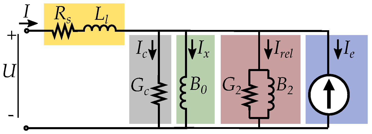
A more detailed model of the magnetic circuit in a machine would treat the leakage flux L l as separated from the magnetizing flux L m [57], as seen in Figure 50a. This can also be extended with the resistive stator copper losses, expressed by the resistance R s (also in Figure 50a). These two series-connected elements ( L l and R s ) will appear more separated in a Norton equivalent model (as in Figure 50b) since the magnetization branch is in parallel with the current source.
The separation between the leakage inductance L l and the magnetization inductance L m can be included in the two circuit equivalents of the two-reaction theory, as shown in Figure 51a. Then, it can be further rewritten as two Norton equivalents, similar to Rahman et al. [56,58] and Sebastian et al. [57] (illustrated in Figure 51b).
Another approach is to include the leakage inductance L l and the stator winding resistance R s in the salient pole machine model discussed in this paper, then with a circuit according to Figure 52.
Circuit models of the core loss resistances are common for transformers but have also been adopted for machine circuits based on Thevenin equivalents [77,78,79,80,81], similar to how iron losses can be adopted in transformer models [82]. With a Norton equivalent, it becomes more similar based on the shunt-connected magnetizing branch I x such that the core losses can be included as an extension in parallel to the magnetizing branch. Such a detailed circuit model can be seen in Figure 53, which includes the core loss resistance G c (which also can be written as G c = G h + G e ).

9. Conclusions

This paper has shown how reluctance torque can be included in circuit models. The effect of the salient poles can be included as its own passive circuit element, as a simple susceptance ( Y 2 = G 2 + j B 2 ), representing the angular variation in reluctance.
The model can be derived by relating the rotating d q -frame of machine modeling to circuit models, where the rotor reference frame is based on the rotor angle while the voltage reference frame is based on the voltage angle.
The proposed model is giving an alternative approach to d q -components in modeling. It is derived by Clarke and Park transforms but can be used without the rotor reference frame. This makes it different compared to the classical approach to salient poles and can simplify the model.
A Norton equivalent is more similar to other circuit models since the inductance of the magnetization is handled as a shunt branch, in parallel with the other components. Such as the magnetization current shunt branch of transformers and induction machines. The approach with a sum of currents also relates better to hysteresis modeling and iron loss modeling. The structure of Norton equivalents is better agreeing with reluctance networks (and Ampere’s law) since series-connected reluctances are equivalent to parallel (shunt) inductors in an electrical circuit.
A Norton equivalent circuit is based on a sum of currents instead of a sum of voltages. This is convenient for simple representation of motor applications when the magnetic flux is set by the stable voltage and frequency of a strong grid or when the magnetic flux is set by flux control of variable speed drives. The formation of the voltage is not in focus, but instead the phase angle of the current.
When synchronous machines with pole saliency become more common in new applications, it is important that the models can handle all types of systems so that all machine designs can be adopted and studied based on basic circuit theory.

Author Contributions

Conceptualization, G.M.; methodology, G.M.; software, G.M.; validation, G.M.; formal analysis, G.M.; investigation, G.M.; resources, G.M.; data curation, G.M.; writing—original draft preparation, G.M.; writing—review and editing, G.M.; visualization, G.M.; supervision, M.L.; project administration, G.M.; funding acquisition, M.L. All authors have read and agreed to the published version of the manuscript.

Funding

The authors would want to thank STandUP for Energy for financial support.

Data Availability Statement

The original contributions presented in the study are included in the article, further inquiries can be directed to the corresponding author.

Conflicts of Interest

The authors declare no conflict of interest.

References

  1. Blondel, A.E. Synchronous Motors and Converters: Theory and Methods of Calculation and Testing; McGraw-Hill: New York, NY, USA, 1913. [Google Scholar]
  2. Park, R.H.; Robertson, B.L. The Reactances of Synchronous Machines. Trans. Am. Inst. Electr. Eng. 1928, 47, 514–535. [Google Scholar] [CrossRef]
  3. Park, R.H. Two-reaction theory of synchronous machines generalized method of analysis-part I. Trans. Am. Inst. Electr. Eng. 1929, 48, 716–727. [Google Scholar] [CrossRef]
  4. Park, R.H. Two-reaction theory of synchronous machines-II. Trans. Am. Inst. Electr. Eng. 1933, 52, 352–354. [Google Scholar] [CrossRef]
  5. Ahmed-Zaid, S.; Mohammadi, D.; Oteafy, A.M.A. A new equivalent circuit of a salient-pole synchronous machine and its phasor interpretation. In Proceedings of the 2015 North American Power Symposium (NAPS), Charlotte, NC, USA, 4–6 October 2015; pp. 1–4. [Google Scholar] [CrossRef]
  6. Ahmed-Zaid, S.; Oteafy, A.M.A. A New Interpretation of the Steady-State Two-Reaction Theory of a Salient-Pole Synchronous Machine. IEEE Access 2022, 10, 128187–128194. [Google Scholar] [CrossRef]
  7. Ibrahim, M.; Pillay, P. Aligning the Reluctance and Magnet Torque in Permanent Magnet Synchronous Motors for Improved Performance. In Proceedings of the 2018 IEEE Energy Conversion Congress and Exposition (ECCE), Portland, OR, USA, 23–27 September 2018; pp. 2286–2291. [Google Scholar] [CrossRef]
  8. Zhao, X.; Kou, B.; Huang, C.; Zhang, L. Optimization Design and Performance Analysis of a Reverse-Salient Permanent Magnet Synchronous Motor. Machines 2022, 10, 204. [Google Scholar] [CrossRef]
  9. Liu, F.; Quan, L.; Zhu, X.; Ge, L.; Wu, W. Reverse Saliency Optimization of Flux-Intensifying Hybrid Permanent Magnet Machine for Variable Speed Applications. IEEE Trans. Appl. Supercond. 2019, 29, 1–5. [Google Scholar] [CrossRef]
  10. Kashif, M.; Singh, B.; Modi, M.; Dudharejiya, D.; Jain, C. Analysis of Reverse-Saliency PMSM with Multiple Flux-Barriers for SWPS. In Proceedings of the 2020 International Conference on Power, Instrumentation, Control and Computing (PICC), Thrissur, India, 17–19 December 2020; pp. 1–5. [Google Scholar] [CrossRef]
  11. Morimoto, S. Trend of permanent magnet synchronous machines. IEEJ Trans. Electr. Electron. Eng. 2007, 2, 101–108. [Google Scholar] [CrossRef]
  12. Tawfiq, K.B.; Ibrahim, M.N.; El-Kholy, E.E.; Sergeant, P. Performance Improvement of Synchronous Reluctance Machines—A Review Research. IEEE Trans. Magn. 2021, 57, 1–11. [Google Scholar] [CrossRef]
  13. Boglietti, A.; Pastorelli, M. Induction and synchronous reluctance motors comparison. In Proceedings of the 2008 34th Annual Conference of IEEE Industrial Electronics, Orlando, FL, USA, 10–13 November 2008; pp. 2041–2044. [Google Scholar] [CrossRef]
  14. de Pancorbo, S.M.; Ugalde, G.; Poza, J.; Egea, A. Comparative study between induction motor and Synchronous Reluctance Motor for electrical railway traction applications. In Proceedings of the 2015 5th International Electric Drives Production Conference (EDPC), Nuremberg, Germany, 15–16 September 2015; pp. 1–5. [Google Scholar] [CrossRef]
  15. Ban, B.; Stipetić, S.; Klanac, M. Synchronous Reluctance Machines: Theory, Design and the Potential Use in Traction Applications. In Proceedings of the 2019 International Conference on Electrical Drives & Power Electronics (EDPE), The High Tatras, Slovakia, 24–26 September 2019; pp. 177–188. [Google Scholar] [CrossRef]
  16. Murataliyev, M.; Degano, M.; Di Nardo, M.; Bianchi, N.; Gerada, C. Synchronous Reluctance Machines: A Comprehensive Review and Technology Comparison. Proc. IEEE 2022, 110, 382–399. [Google Scholar] [CrossRef]
  17. Hoffer, A.E.; Moncada, R.H.; Pavez, B.J.; Tapia, J.A.; Laurila, L. A high efficiency control strategy for synchronous reluctance generator including saturation. In Proceedings of the 2016 XXII International Conference on Electrical Machines (ICEM), Lausanne, Switzerland, 4–7 September 2016; pp. 39–45. [Google Scholar] [CrossRef]
  18. Huynh, T.A.; Hsieh, M.F. Comparative Study of PM-Assisted SynRM and IPMSM on Constant Power Speed Range for EV Applications. IEEE Trans. Magn. 2017, 53, 1–6. [Google Scholar] [CrossRef]
  19. Ngo, D.K.; Hsieh, M.F.; Huynh, T.A. Torque Enhancement for a Novel Flux Intensifying PMa-SynRM Using Surface-Inset Permanent Magnet. IEEE Trans. Magn. 2019, 55, 1–8. [Google Scholar] [CrossRef]
  20. Hsieh, M.F.; Ngo, D.K.; Thao, N.G.M. Flux Intensifying Feature of Permanent Magnet Assisted Synchronous Reluctance Motor with High Torque Density. Electronics 2022, 11, 397. [Google Scholar] [CrossRef]
  21. Wang, Y.; Bianchi, N.; Qu, R. Comparative Study of Non-Rare-Earth and Rare-Earth PM Motors for EV Applications. Energies 2022, 15, 2711. [Google Scholar] [CrossRef]
  22. Xie, Y.; Shao, J.; He, S.; Ye, B.; Yang, F.; Wang, L. Novel PM-Assisted Synchronous Reluctance Machines Using Asymmetrical Rotor Configuration. IEEE Access 2022, 10, 79564–79573. [Google Scholar] [CrossRef]
  23. Bianchi, N. Synchronous reluctance and interior permanent magnet motors. In Proceedings of the 2013 IEEE Workshop on Electrical Machines Design, Control and Diagnosis (WEMDCD), Paris, France, 11–12 March 2013; pp. 75–84. [Google Scholar] [CrossRef]
  24. Johnson, D. Origins of the equivalent circuit concept: The current-source equivalent. Proc. IEEE 2003, 91, 817–821. [Google Scholar] [CrossRef]
  25. Johnson, D. Origins of the equivalent circuit concept: The voltage-source equivalent. Proc. IEEE 2003, 91, 636–640. [Google Scholar] [CrossRef]
  26. Brittain, J. Thevenin’s theorem. IEEE Spectr. 1990, 27, 42. [Google Scholar] [CrossRef]
  27. Anttila, S.; Döhler, J.S.; Oliveira, J.G.; Boström, C. Grid Forming Inverters: A Review of the State of the Art of Key Elements for Microgrid Operation. Energies 2022, 15, 5517. [Google Scholar] [CrossRef]
  28. Rocabert, J.; Luna, A.; Blaabjerg, F.; Rodríguez, P. Control of Power Converters in AC Microgrids. IEEE Trans. Power Electron. 2012, 27, 4734–4749. [Google Scholar] [CrossRef]
  29. Doherty, R.E.; Shirley, O.E. Reactance of Synchronous Machines and its Applications. Trans. Am. Inst. Electr. Eng. 1918, XXXVII, 1209–1340. [Google Scholar] [CrossRef]
  30. Doherty, R.E.; Nickle, C.A. Synchronous machines I-an extension of blondel’s two-reaction theory. Trans. Am. Inst. Electr. Eng. 1926, XLV, 912–947. [Google Scholar] [CrossRef]
  31. Doherty, R.E.; Nickle, C.A. Synchronous Machines-III Torque-Angle Characteristics Under Transient Conditions. Trans. Am. Inst. Electr. Eng. 1927, XLVI, 1–18. [Google Scholar] [CrossRef]
  32. Doherty, R.E.; Nickle, C.A. Synchronous Machines-IV. Trans. Am. Inst. Electr. Eng. 1928, 47, 457–487. [Google Scholar] [CrossRef]
  33. Clarke, E.; Weygandt, C.N.; Concordia, C. Overvoltages caused by unbalanced short circuits: Effect of amortisseur windings. Electr. Eng. 1938, 57, 453–468. [Google Scholar] [CrossRef]
  34. Park, R.H.; Skeats, W.F. Circuit Breaker Recovery Voltages Magnitudes and Rates of Rise. Trans. Am. Inst. Electr. Eng. 1931, 50, 204–238. [Google Scholar] [CrossRef]
  35. Kimbark, E.W. Two-phase co-ordinates of a three-phase circuit. Electr. Eng. 1939, 58, 894–910. [Google Scholar] [CrossRef]
  36. Duesterhoeft, W.C.; Schulz, M.W.; Clarke, E. Determination of Instantaneous Currents and Voltages by Means of Alpha, Beta, and Zero Components. Trans. Am. Inst. Electr. Eng. 1951, 70, 1248–1255. [Google Scholar] [CrossRef]
  37. Chattopadhyay, S.; Mitra, M.; Sengupta, S. Clarke and Park Transform. In Electric Power Quality; Springer: Dordrecht, The Netherlands, 2011; pp. 89–96. [Google Scholar] [CrossRef]
  38. O’Rourke, C.J.; Qasim, M.M.; Overlin, M.R.; Kirtley, J.L. A Geometric Interpretation of Reference Frames and Transformations: dq0, Clarke, and Park. IEEE Trans. Energy Convers. 2019, 34, 2070–2083. [Google Scholar] [CrossRef]
  39. Ilyasov, R.I. The Phasor Diagram of a Superconducting Synchronous Electrical Machine. Inventions 2023, 8, 68. [Google Scholar] [CrossRef]
  40. Madnani, R.; Mishra, M.K. A visual understanding of electrical transformations and generalized abc to αβ0 and dq0 transformation. Int. J. Circuit Theory Appl. 2023, 51, 963–978. [Google Scholar] [CrossRef]
  41. Fortescue, C.L. Method of Symmetrical Co-Ordinates Applied to the Solution of Polyphase Networks. Trans. Am. Inst. Electr. Eng. 1918, XXXVII, 1027–1140. [Google Scholar] [CrossRef]
  42. Fortescue, C.L. Method of symmetrical co-ordinates applied to the solution of polyphase networks. Proc. Am. Inst. Electr. Eng. 1918, 37, 629–716. [Google Scholar] [CrossRef]
  43. Nee, H.P.; Lefevre, L.; Thelin, P.; Soulard, J. Determination of d and q reactances of permanent-magnet synchronous motors without measurements of the rotor position. IEEE Trans. Ind. Appl. 2000, 36, 1330–1335. [Google Scholar] [CrossRef]
  44. Rallabandi, V.; Taran, N.; Ionel, D.M.; Zhou, P. Inductance Testing for IPM Synchronous Machines According to the New IEEE Std 1812 and Typical Laboratory Practices. IEEE Trans. Ind. Appl. 2019, 55, 2649–2659. [Google Scholar] [CrossRef]
  45. IEEE Std 115-2019 (Revision of IEEE Std 115-2009); IEEE Guide for Test Procedures for Synchronous Machines Including Acceptance and Performance Testing and Parameter Determination for Dynamic Analysis. IEEE: Piscataway, NJ, USA, 2020; pp. 1–246. [CrossRef]
  46. Gao, Y.; Qu, R.; Li, D. Improved hybrid method to calculate inductances of permanent magnet synchronous machines with skewed stators based on winding function theory. Chin. J. Electr. Eng. 2016, 2, 52–61. [Google Scholar] [CrossRef]
  47. Kim, S.H. Chapter 3—Alternating current motors: Synchronous motor and induction motor. In Electric Motor Control: DC, AC and BLDC Motors; Kim, S.H., Ed.; Elsevier: Amsterdam, The Netherlands, 2017; pp. 95–152. [Google Scholar] [CrossRef]
  48. Ichikawa, O. 12—Synchronous reluctance bearingless motors. In Magnetic Bearings and Bearingless Drives; Chiba, A., Fukao, T., Ichikawa, O., Oshima, M., Takemoto, M., Dorrell, D.G., Eds.; Newnes: Oxford, UK, 2005; pp. 238–250. [Google Scholar] [CrossRef]
  49. Vo-Duy, T.; Ta, M.C. Fundamental design of electric motor control systems. In Encyclopedia of Electrical and Electronic Power Engineering; García, J., Ed.; Elsevier: Oxford, UK, 2023; pp. 428–453. [Google Scholar] [CrossRef]
  50. Hughes, A.; Drury, B. Chapter 9—Synchronous, permanent magnet and reluctance motors and drives. In Electric Motors and Drives, 5th ed.; Hughes, A., Drury, B., Eds.; Newnes: London, UK, 2019; pp. 307–373. [Google Scholar] [CrossRef]
  51. Murty, P. Chapter 8—Synchronous Machine. In Power Systems Analysis, 2nd ed.; Murty, P., Ed.; Butterworth-Heinemann: Boston, MA, USA, 2017; pp. 149–174. [Google Scholar] [CrossRef]
  52. Hayes, J.G.; Goodarzi, G.A. Electric Powertrain: Energy Systems, Power Electronics and Drives for Hybrid, Electric and Fuel Cell Vehicles; Wiley: Hoboken, NJ, USA, 2018. [Google Scholar]
  53. Hamill, D. Lumped equivalent circuits of magnetic components: The gyrator-capacitor approach. IEEE Trans. Power Electron. 1993, 8, 97–103. [Google Scholar] [CrossRef]
  54. Lambert, M.; Mahseredjian, J.; Martínez-Duró, M.; Sirois, F. Magnetic Circuits Within Electric Circuits: Critical Review of Existing Methods and New Mutator Implementations. IEEE Trans. Power Deliv. 2015, 30, 2427–2434. [Google Scholar] [CrossRef]
  55. Hamilton, N. Ferrites: Magnetic and electric equivalent circuits and the complex permeability spectra. In Proceedings of the Active and Passive RF Devices Seminar, London, UK, 17 February 2016; pp. 1–8. [Google Scholar] [CrossRef]
  56. Rahman, M.; Little, T.; Slemon, G. Analytical models for interior-type permanent magnet synchronous motors. IEEE Trans. Magn. 1985, 21, 1741–1743. [Google Scholar] [CrossRef]
  57. Sebastian, T.; Slemon, G.; Rahman, M. Modelling of permanent magnet synchronous motors. IEEE Trans. Magn. 1986, 22, 1069–1071. [Google Scholar] [CrossRef]
  58. Rahman, M. Analytical models for exterior-type permanent magnet synchronous motors. IEEE Trans. Magn. 1987, 23, 3625–3627. [Google Scholar] [CrossRef]
  59. Slemon, G.R. Analytical Models for Saturated Synchronous Machines. IEEE Trans. Power Appar. Syst. 1971, PAS-90, 409–417. [Google Scholar] [CrossRef]
  60. Fasil, M.; Antaloae, C.; Mijatovic, N.; Jensen, B.B.; Holboll, J. Improved dq-Axes Model of PMSM Considering Airgap Flux Harmonics and Saturation. IEEE Trans. Appl. Supercond. 2016, 26, 1–5. [Google Scholar] [CrossRef]
  61. Nakamura, K.; Saito, K.; Watanabe, T.; Ichinokura, O. A new nonlinear magnetic circuit model for dynamic analysis of interior permanent magnet synchronous motor. J. Magn. Magn. Mater. 2005, 290–291, 1313–1317. [Google Scholar] [CrossRef]
  62. Chiba, A. 7—Analysis in rotational coordinates and magnetic suspension strategy for bearingless drives with 2-pole and 4-pole windings. In Magnetic Bearings and Bearingless Drives; Chiba, A., Fukao, T., Ichikawa, O., Oshima, M., Takemoto, M., Dorrell, D.G., Eds.; Newnes: Oxford, UK, 2005; pp. 159–183. [Google Scholar] [CrossRef]
  63. Gabriel, F.; De Belie, F.; Druyts, P.; Neyt, X.; Melkebeek, J.; Acheroy, M. Compensating the influence of the stator resistor and inverter nonlinearities in signal-injection based sensorless strategies. In Proceedings of the 2009 IEEE Vehicle Power and Propulsion Conference, Dearborn, MI, USA, 7–10 September 2009; pp. 283–290. [Google Scholar] [CrossRef]
  64. Eilenberger, A.; Schroedl, M.; Heissenberger, J. Comparison of outer rotor PMSM with single- and double-layer windings at same machine geometry with respect to the sensorless control capability. In Proceedings of the 2009 13th European Conference on Power Electronics and Applications, Barcelona, Spain, 8–10 September 2009; pp. 1–7. [Google Scholar]
  65. Schroedl, M. Sensorless control of AC machines at low speed and standstill based on the "INFORM" method. In Proceedings of the IAS ’96. Conference Record of the 1996 IEEE Industry Applications Conference Thirty-First IAS Annual Meeting, San Diego, CA, USA, 6–10 October 1996; Volume 1, pp. 270–277. [Google Scholar] [CrossRef]
  66. De Belie, F.; Melkebeek, J.; Vandevelde, L.; Boel, R.; Geldhof, K.; Vyncke, T. A nonlinear model for synchronous machines to describe high-frequency signal based position estimators. In Proceedings of the IEEE International Conference on Electric Machines and Drives, San Antonio, TX, USA, 15 May 2005; pp. 696–703. [Google Scholar] [CrossRef]
  67. Mohanarajah, T.; Hellany, A.; Rizk, J.; Nagrial, M. Analysis and design of high-performance synchronous reluctance machine. In Proceedings of the 2018 IEEE 12th International Conference on Compatibility, Power Electronics and Power Engineering (CPE-POWERENG 2018), Doha, Qatar, 10–12 April 2018; pp. 1–6. [Google Scholar] [CrossRef]
  68. Heidari, H.; Rassõlkin, A.; Kallaste, A.; Vaimann, T.; Andriushchenko, E.; Belahcen, A.; Lukichev, D.V. A Review of Synchronous Reluctance Motor-Drive Advancements. Sustainability 2021, 13, 729. [Google Scholar] [CrossRef]
  69. Vartanian, R.; Toliyat, H.A.; Akin, B.; Poley, R. Power factor improvement of synchronous reluctance motors (SynRM) using permanent magnets for drive size reduction. In Proceedings of the 2012 Twenty-Seventh Annual IEEE Applied Power Electronics Conference and Exposition (APEC), Orlando, FL, USA, 5–9 February 2012; pp. 628–633. [Google Scholar] [CrossRef]
  70. Steinmetz, C.P. On the Law of Hysteresis. Trans. Am. Inst. Electr. Eng. 1892, IX, 1–64. [Google Scholar] [CrossRef]
  71. Steinmetz, C.P. On the Law of Hysteresis (Part II.) and Other Phenomena of the Magnetic Circuit. Trans. Am. Inst. Electr. Eng. 1892, IX, 619–758. [Google Scholar] [CrossRef]
  72. Steinmetz, C.P. On the Law of Hysteresis (Part III.), and the Theory of Ferric Inductances. Trans. Am. Inst. Electr. Eng. 1894, XI, 570–616. [Google Scholar] [CrossRef]
  73. O’Kelly, D. Flux penetration in a ferromagnetic material including hysteresis and eddy-current effects. J. Phys. D Appl. Phys. 1972, 5, 203. [Google Scholar] [CrossRef]
  74. Zaher, F. An analytical solution for the field of a hysteresis motor based on complex permeability. IEEE Trans. Energy Convers. 1990, 5, 156–163. [Google Scholar] [CrossRef]
  75. Tavakoli, H.; Bormann, D.; Ribbenfjärd, D.; Engdahl, G. Comparison of a simple and a detailed model of magnetic hysteresis with measurements on electrical steel. COMPEL-Int. J. Comput. Math. Electr. Electron. Eng. 2009, 28, 700–710. [Google Scholar] [CrossRef]
  76. Glover, J.D.; Overbye, T.J.; Sarma, M.S. Power System Analysis & Design, 6th ed.; Cengage Learning: Boston, MA, USA, 2017. [Google Scholar]
  77. Li, S.; Haskew, T.A.; Hong, Y.K. Characteristic study of vector-controlled permanent magnet synchronous motor in electric drive vehicles. In Proceedings of the PES T&D 2012, Orlando, FL, USA, 7–10 May 2012; pp. 1–8. [Google Scholar] [CrossRef]
  78. Li, Q.; Fan, T.; Wen, X. Characterization of Iron Loss for Integral-Slot Interior Permanent Magnet Synchronous Machine During Flux Weakening. IEEE Trans. Magn. 2017, 53, 1–8. [Google Scholar] [CrossRef]
  79. Asef, P.; Bargallo, R.; Lapthorn, A. Iron Loss Prediction Using Modified IEM-Formula during the Field Weakening for Permanent Magnet Synchronous Machines. Machines 2017, 5, 30. [Google Scholar] [CrossRef]
  80. Zhu, Z.Q.; Xue, S.; Chu, W.; Feng, J.; Guo, S.; Chen, Z.; Peng, J. Evaluation of Iron Loss Models in Electrical Machines. IEEE Trans. Ind. Appl. 2019, 55, 1461–1472. [Google Scholar] [CrossRef]
  81. Shutta, Y.; Takahashi, Y.; Fujiwara, K. Behavioral modeling of permanent magnet synchronous motor fed by PWM inverters considering iron losses due to carrier harmonics. Electr. Eng. Jpn. 2020, 210, 37–46. [Google Scholar] [CrossRef]
  82. Chen, W.; Ma, J.; Huang, X.; Fang, Y. Predicting Iron Losses in Laminated Steel with Given Non-Sinusoidal Waveforms of Flux Density. Energies 2015, 8, 13726–13740. [Google Scholar] [CrossRef]
Figure 1. Model of a synchronous machine, considering salient poles with reluctance torque.
Energies 17 01015 g001
Figure 2. Model of a synchronous reluctance machines based on a sum of the currents I x and I r e l .
Energies 17 01015 g002
Figure 3. Analogy of a DC machine. (a) Excitation flux from poles. (b) Armature reaction flux. (c) resultant flux.
Energies 17 01015 g003
Figure 4. Load angle of a synchronous machine, in this case a generator with the rotor flux leading the stator flux. Showing: (a) A no-load case δ = 0 . (b) A case with a load δ 0 .
Energies 17 01015 g004
Figure 5. Phasor diagram linked to the rotation of the rotor, illustrated for a generator (a) and a motor (b). The rotor reference frame is based on the excitation flux Ψ m in the d-direction, with the resulting EMF is in the q-direction. The stator flux Ψ and stator voltage U are shifted with the load angle δ .
Energies 17 01015 g005
Figure 6. The two separated circuits in the two-reaction theory. The voltage U q (a) in the q-direction is based on the flux linkage (b) in the d-direction. The voltage U d (c) in the d-direction is based on the flux linkage (d) in the q-direction.
Energies 17 01015 g006
Figure 8. The magnetic field in a synchronous machine rotates with the rotor. The rotation is described in the α β -frame.
Energies 17 01015 g008
Figure 9. The three reference frames. (a) The three phases are located in the stator reference. (b) The equivalent stator reference frame that describes a rotation. (c) The rotating rotor reference frame.
Energies 17 01015 g009
Figure 10. (a) Three phases, a b c . (b) Clarke transform, α β . (c) Park transform, d q .
Energies 17 01015 g010
Figure 11. Inductance L as a function of the rotor position θ , expressed as a DC offset and a second-order harmonic.
Energies 17 01015 g011
Figure 12. Three phases’ inductance values with self-inductance and mutual inductance.
Energies 17 01015 g012
Figure 13. Calculation diagram for a method with matrix representation.
Energies 17 01015 g013
Figure 14. The voltage reference frame is placed with an angle 90 δ relative to the rotor reference frame. Examples showing (a) δ > 0 , generator. (b) δ < 0 , motor.
Energies 17 01015 g014
Figure 15. An alternative approach to model salient pole machines, based on X 0 and X 2 . (a) Circuit representation of the alternative model (b) Phasor diagram in alternative model. (c) Phasor diagram in the classical approach.
Energies 17 01015 g015
Figure 16. Reluctance R as a function of the rotor position angle θ .
Energies 17 01015 g016
Figure 17. Components of the reluctance matrix of a three-phase system in a machine. Equivalent to self-inductance and mutual inductance.
Energies 17 01015 g017
Figure 18. (a) A Thevenin equivalent is equivalent to a (b) flux source reluctance model. (c) A Norton equivalent is equivalent to a (d) MMF source reluctance model.
Energies 17 01015 g018
Figure 19. (a) A reluctance circuit model of a salient pole synchronous machine. (b) An electrical circuit model of a salient pole synchronous machine.
Energies 17 01015 g019
Figure 20. Electric circuit models of (non-salient pole) synchronous machines. (a) A Thevenin equivalent and (b) a Norton Equivalent.
Energies 17 01015 g020
Figure 21. Current source in a Norton equivalent, equivalent to the EMF. Showing: (a) I ¯ N (b) I ¯ e .
Energies 17 01015 g021
Figure 22. (a) The load angle δ is the phase shift between the magnetic flux ψ and the equivalent current source i N of the Norton equivalent. (b) Load angle for the alternative representation with i e .
Energies 17 01015 g022
Figure 23. Current equivalent of excitation current is modeled as a phasor I ¯ e , located at 90 + δ . Showing (a) δ < 0 (motor). (b) δ = 0 (no load). (c) δ > 0 (generator). Based on the transformed field current I f and the load angle δ .
Energies 17 01015 g023
Figure 24. Phasor representation of the excitation current. (a) Minimum load angle δ = 0 . (b) Any load angle δ . (c) Maximum load angle δ = 90 .
Energies 17 01015 g024
Figure 25. The current phasors I e and I x . (a) Rotor reference frame, (b) voltage reference frame.
Energies 17 01015 g025
Figure 26. Phasor illustration of the current in a model of a non-salient pole machine. The current I x is orthogonal to the voltage, but the current I e is dependent on the load angle. Showing load angles: (a) δ = 0 . (b) δ = 45 . (c) δ = 90 .
Energies 17 01015 g026
Figure 27. Phasor diagram for a reluctance circuit, illustrating field weakening. (a) Case with current I in same angle as EMF. (b) Case with field weakening with the angle of the current I changed to decrease the flux Φ .
Energies 17 01015 g027
Figure 28. Phasor diagram for a current-equivalent circuit, illustrating Field Weakening. (a) Case with current I in same angle as EMF. (b) Case with field weakening with the angle of the current I changed to decrease the magnetizing current I m = I x (related to the flux).
Energies 17 01015 g028
Figure 29. Limits in the armature current I and the magnetization current I m = Y U (of the flux). (a) Shown in the rotor reference frame ( d q -plane). (b) Shown in the voltage reference frame ( r i -plane).
Energies 17 01015 g029
Figure 30. (a) Phasor representation of the currents I = I m + I e . (b) The limitation in currents, which are relevant for field weakening.
Energies 17 01015 g030
Figure 31. Models of synchronous machines, considering salient poles with reluctance torque.
Energies 17 01015 g031
Figure 32. Transformer models have the magnetization inductance as a shunt branch, similar to the Norton equivalent model.
Energies 17 01015 g032
Figure 33. Induction machines also have the magnetization branch as a shunt, similar to Norton equivalent models of synchronous machines.
Energies 17 01015 g033
Figure 34. A typical “V curve”, showing how the magnitude armature current I depends on the field current I f .
Energies 17 01015 g034
Figure 35. The magnetization current is the same, but the current of the current source increases. Assuming constant voltage and no load angle for illustrative purposes.
Energies 17 01015 g035
Figure 36. The phase angle of the current I = I x + I e is controlled by variations in the field current I f . It can be illustrated by variations in the magnitude of the equivalent current source I e , equivalent to variations in the EMF E. (a) Under-excitation (motor, lagging p.f.). (b) Unity power factor. (c) Over-excitation (motor, leading p.f.).
Energies 17 01015 g036
Figure 37. The torque of a magnetized rotor (acting like a magnetic dipole) in a magnetic flux from a stator.
Energies 17 01015 g037
Figure 38. The reluctance torque depending on the rotor position relative to the magnetic flux from the stator.
Energies 17 01015 g038
Figure 39. An example of a torque curve, with the torque as a function of the load angle. The complete torque is a combination of the excitation torque (from the field windings or permanent magnets) and the reluctance torque (from the pole saliency).
Energies 17 01015 g039
Figure 40. An example of a torque curve with reverse saliency. The reluctance torque contribute to the combined torque in an opposite way in comparison to common reluctance torque.
Energies 17 01015 g040
Figure 41. Circuit models of salient pole synchronous machine. (a) Model with a variable current source representing the saliency I ¯ r e l . (b) Model with a susceptance Y 2 ¯ = G 2 + j B 2 representing the saliency.
Energies 17 01015 g041
Figure 42. Current limitations for field weakening, considering voltage limitations for different frequencies. (a) For a Salient pole synchronous machine ( L d > L q ). (b) Reluctance machine ( L d > L q ).
Energies 17 01015 g042
Figure 43. Phasors of the magnetization current and the saliency current. (a) The average susceptance gives a contribution of an inductive current I x , placed 90 from the voltage. (b) The saliency susceptance gives a current contribution I r e l based on a reflection of the voltage in the line d = q .
Energies 17 01015 g043
Figure 44. Phasor representation of the current of the saliency susceptance. (a) Minimum load angle δ = 0 . (b) Any load angle δ . (c) Maximum load angle δ = 45 .
Energies 17 01015 g044
Figure 45. (a) Possible magnetization currents I of a reluctance machine expressed as a region in the d q -plane. (b) Example of currents in two parts at δ = 45 , (c) rewritten in the voltage reference frame.
Energies 17 01015 g045
Figure 46. Magnetization Current for different load angles. Expressed as I = I x + I r e l . (a) δ = 0 , (b) δ = 45 , (c) δ = 90 (unstable).
Energies 17 01015 g046
Figure 47. Circuit model with a saliency susceptance (a) case at 0° when the susceptance only is an imaginary part. (b) A case at 22.5° with both a real and an imaginary part. (c) A case at 45° where the saliency susceptance only is a real part.
Energies 17 01015 g047
Figure 48. (a) Phase diagram of the complex reluctance, modeling the reluctance torque. (b) Adopted as a susceptance.
Energies 17 01015 g048
Figure 49. (a) A circuit element model of the magnetization of iron considering hysteresis and eddy currents. (b) The frequency of the conductance in hysteresis modeling resembles that of the salient pole model.
Energies 17 01015 g049
Figure 50. (a) Classical Thevenin equivalent model, extended with series stator resistance and leakage flux inductance. (b) The model rewritten as a Norton equivalent, also with series stator resistance and leakage flux inductance.
Energies 17 01015 g050
Figure 51. (a) Classical Thevenin equivalent model with separate d q -components, extended with series stator resistance and leakage flux inductance. (b) The two d q -components in the model rewritten as Norton equivalents.
Energies 17 01015 g051
Figure 52. (a) Classical model with series components. (b) The model of this paper, extended with leakage inductance and stator series resistance.
Energies 17 01015 g052
Figure 53. A more detailed model of a salient pole synchronous machine, including leakage flux inductance, stator copper loss resistance, and iron loss resistance.
Energies 17 01015 g053
Disclaimer/Publisher’s Note: The statements, opinions and data contained in all publications are solely those of the individual author(s) and contributor(s) and not of MDPI and/or the editor(s). MDPI and/or the editor(s) disclaim responsibility for any injury to people or property resulting from any ideas, methods, instructions or products referred to in the content.