Article

Production of CH4/C3H8 (85/15 vol%) Hydrate in a Lab-Scale Unstirred Reactor: Quantification of the Promoting Effect Due to the Addition of Propane to the Gas Mixture

by
Alberto Maria Gambelli
1,*,
Giovanni Gigliotti
1 and
Federico Rossi
2
1
Department of Civil and Environmental Engineering, University of Perugia, Via G. Duranti 93, 06125 Perugia, Italy
2
Engineering Department, University of Perugia, Via G. Duranti 93, 06125 Perugia, Italy
*
Author to whom correspondence should be addressed.
Energies 2024, 17(5), 1104; https://doi.org/10.3390/en17051104
Submission received: 25 January 2024 / Revised: 20 February 2024 / Accepted: 22 February 2024 / Published: 26 February 2024
(This article belongs to the Special Issue Gas Hydrates: A Future Clean Energy Resource)

Abstract

:
By itself, propane is capable to form hydrates at extremely contained pressures, if compared with the values typical of “guests” such as methane and carbon dioxide. Therefore, its addition in mixtures with gases such as those previously mentioned is expected to reduce the pressure required for hydrate formation. When propane is mixed with carbon dioxide, the promoting effect cannot be observed since, due to their molecular size, these two molecules cannot fit in the same unit cell of hydrates. Therefore, each species produces hydrates independently from the other, and the beneficial effect is almost completely prevented. Conversely, if propane is mixed with methane, the marked difference in size, together with the capability of methane molecules to fit in the smaller cages of both sI and sII structures, will allow to form hydrates in thermodynamic conditions lower than those required for pure methane hydrates. This study aims to experimentally characterize such a synergistic and promoting effect, and to quantity it from a thermodynamic point of view. Hydrates were formed and dissociated within a silica porous sediment and the results were compared with the phase boundary equilibrium conditions for pure methane hydrates, defined according to experimental values available elsewhere in the literature. The obtained results were finally explained in terms of cage occupancy.

1. Introduction

Gas hydrates consist of non-stoichiometric clathrate structures composed by water molecules, referred to as “hosts”, which form hydrogen bonds with the surrounding molecules and trap gaseous molecules, called “guests” within ordered and crystalline cages [1]. Several gaseous species can lead to the production of hydrates, including methane, small–chain hydrocarbons, carbon dioxide, nitrogen, hydrogen, carbon monoxide, and others [2]. These different species have hydrophobicity as a common property; however, some relevant exceptions exist, such as hydrogen and carbon dioxide. The gaseous molecules are only physically included within the hydrate lattice: their interaction with water molecules only consists of Van der Waals forces. The rupture of Van der Waals bonds requires 0.3 kcal/mol, while approximately 5 kcal/mol is needed to break hydrogen bonds [3].
The term “natural gas hydrates” refers to the group of naturally occurring clathrates containing small molecules of alkanes (such as methane, ethane, propane, and butane), together with CO2, N2, H2S, and traces of further species [4,5]. To form, gas hydrates need the intimate contact between host and guest molecules, together with suitable thermodynamic conditions, or enough elevated pressure and low temperature, whose specific values are a function of the guest involved in the process [6,7].
The typology of the guest is also responsible for the reticular structure assumed by the hydrate lattice: five different cavities are possible, with different sizes and shapes, thus capable to host different guest species. The aggregation of these cavities leads to the occurrence of three possible naturally occurring unit cells: the cubic sI, the cubic sII, and the hexagonal sH.
The five polyhedral cavities are indicated with the nomenclature “ n i m i ”, where “ni” refers to the number of edges in the “i” face, while “mi” represents the number of faces having “ni” edges. Ordered as a function of their growing size, the five possible cavities are pentagonal dodecahedron (512), tetrakaidecahedron (51262), hexakaidecahedron (51264), irregular dodecahedron (435663), and icosahedron (51268).
The unit cell of sI includes two 512 and six 14-hedra; it is the most diffused in nature and is typical of guest molecules such as methane and carbon dioxide [8]. The cubic sII consists of sixteen 512 and eight 16-hedra and hosts molecules with a larger diameter, such as propane and butane. The hexagonal sH is the less diffused in nature and, to occur, it needs the simultaneous presence of relatively small- and large-diameter guests [9]. More details about hydrate structures are provided in the next section.
The mechanism behind gas hydrate formation and dissociation can be advantageously exploited for several key applications, such as gas storage and transportation [10], the separation of gas mixtures into single species [11], cold storage [12], climate change mitigation [13], seawater desalination [14], and, more generally, waste water treatment [15], sludge dewatering [16,17], carbon dioxide capture and final disposal, and so on.
Gas storage is particularly feasible, since hydrates can contain a relatively huge amount of gas per unit of volume and at contained pressures, if compared with traditional storage techniques. For instance, one cubic meter of hydrate can contain up to 172 m3 of methane [18,19] and 478 m3 of hydrogen [20]. The storage of gas in solid form also makes the transportation phase easier and safer. Different guest species are enclathrated in different thermodynamic conditions. Therefore, if the process is carried out at the appropriate pressure and temperature, it may involve or exclude specific species from the gaseous mixture, thus favouring their separation. Cold storage via hydrate formation was found to be less energy intensive than the currently diffused option, based on ice [21] and eutectic salts [22,23]. The production of these compounds for climate change mitigation is directly related to their capability to store huge quantities of gas, for instance, carbon dioxide, into relatively contained volumes and in mild thermodynamic conditions.
Similar to ice, the crystalline structure of gas hydrates cannot involve elements diffused in water such as ions, impurities, pollutants, and so on [24]. Therefore, their production in contaminated water allows researchers to obtain pure water and, at the same time, to concentrate contaminants in a lower volume, thus facilitating their final recovery and disposal [25,26,27,28].
However, the main interest still remains the production of energy from the naturally occurring reservoirs. Considering the quantity of gas which can be captured per unit of volume, one cubic meter of methane hydrates can produce up to 35.79 MJ [29]. If this value is multiplied by the amount of methane present in hydrate reservoirs, estimated to range from 1015 to 1017 m3 (in standard conditions) [30], the potential of exploiting hydrates as an alternative energy source, for the transition towards renewable energy sources, clearly emerges [31,32].
The main techniques designed for the extraction of methane from natural reservoirs are depressurization [33,34], thermal stimulation [35,36], chemical inhibitor injection [37,38], or a combination of these [39]. All these techniques allow the rupture of crystalline water cages, thus causing the release of methane contained in them.
A further mechanism for energy production from gas hydrates was proposed for the first time in 1980 and is based on the extraction of methane with the simultaneous injection of carbon dioxide [40]. The so-called Replacement Process allows researchers to pursue several goals together: (i) energy production; (ii) the permanent disposal of carbon dioxide, and (iii) the preservation of crystalline structures. The removal of gas from water cages leads to the disruption of the hydrate lattice, with the consequent deformation of soils. Conversely, replacement allows the guest molecule to be exchanged directly within the cavity, thus preserving its integrity. Moreover, in the same thermodynamic conditions, hydrates containing carbon dioxide are more stable than those containing exclusively methane. The simultaneous presence of both guest species improves the mechanical properties of hydrates, whose strength could theoretically become twenty times higher than that of pure ice [41].
Since CO2 hydrates require milder thermodynamic conditions to occur, the difference in phase equilibrium boundaries of hydrates made with the two gases defines a thermodynamic region available for the replacement process [42].
Despite the enormous potentialities, the application of replacement strategies is currently limited to a few field tests. The reason can be attributed to the overall low efficiency of the process and the consequent high costs per unit of energy produced.
Such a problem can be attributed to the following causes:
(i)
Limitations due to the heat and mass transfer properties of the system;
(ii)
The thermodynamic region, existing between the phase equilibrium curves of pure methane and carbon dioxide hydrates, is relatively narrow;
(iii)
If the process is carried out with pure carbon dioxide, the maximum ideal efficiency is much lower than one;
(iv)
The local concentration of replacing and replaced species plays a crucial role.
Moreover, sediments hosting the hydrate reservoir play a key role in evaluating the overall process efficiency and their action on parameters such as hydrate saturation degree, formation rate, and permeability must be experimentally investigated [43,44,45].
In greater detail, the maximum theoretical efficiency is lower than one due to the different molecular size of the two molecules. The unit cell of sI contains two different types of polyhedral cavity, the small 512 and the larger 51262. While methane can easily fit in both types of cavities, the molecule of carbon dioxide prefers the larger ones and, as a consequence, the replacement of methane in the small cavities is strongly hindered. More details about the replacement mechanism are provided in the next section. Such a problem can be solved by using CO2-based mixtures instead of pure carbon dioxide. The addition of molecules with a smaller diameter, such as nitrogen and hydrogen, allows methane to also be replaced also in the small cavities; however, the presence of those molecules changes the phase equilibrium of the system and often leads to higher formation pressures, thus reducing the tightness of the region that is suitable for replacement [46].
Conversely, the usage of molecules with a larger diameter than carbon dioxide, such as propane and butane, favours the enclathration process and reduces the required pressures. Unfortunately, these molecules cannot enter into 512 cages and also require the transition of structures from sI to sII. Therefore, the replacement mechanism has to be definitively revised.
Previous studies confirmed that, when the replacement process is carried out with CO2/C3H8 mixtures, the presence of propane enhances the process, improving the quantity of methane recovered and, at the same time, favouring the capture of carbon dioxide. However, the direct participation of propane to the production of hydrates remains limited [47].
To better understand the replacement mechanism in the presence of propane, its role on the formation of methane and carbon dioxide hydrates needs to be investigated.
This study firstly discusses the possible role of propane, based on its molecular diameter and on the phase equilibrium boundary of hydrates containing it. Moreover, this article experimentally investigates the production of hydrates with a binary CH4/C3H8 mixture, with a concentration equal to 85/15 vol%.

2. Role of C3H8 in the Capture of CO2 and CH4 into Hydrate Structures

The following diagram shows the phase boundary equilibrium conditions of methane [48,49,50,51], carbon dioxide [52,53,54,55], and propane [56,57] hydrates, within 0–10 °C and below 50 bar.
As is visible from Figure 1, the equilibrium conditions of gas hydrates strongly depend on the type of guest molecules involved in the process. Methane and carbon dioxide form sI hydrates, while propane forms sII hydrates. All species require higher pressures with the increase in temperature. However, the dependency of these two parameters is linear (in the thermodynamic range selected) for methane and carbon dioxide hydrates, while it shows a marked deviation for propane hydrates.
At temperatures within 0–5.5 °C, the larger the molecular diameter, the lower the formation pressure. Conversely, at higher temperatures, the equilibrium curve of propane hydrates shows a marked deviation, and the enclathration process becomes less favoured than for methane and carbon dioxide.
When hydrates are produced with binary gas mixtures, the formation conditions are expected to fall between the two-phase equilibrium curves corresponding to hydrates containing only one of the two guest species. However, such a condition is not true for all possible binary guest mixtures. If the mixture contains propane and carbon dioxide, the thermodynamics could remain the same as that of pure carbon dioxide hydrates. By itself, carbon dioxide forms sI hydrates, while propane forms sII. The two structures have the same small cage, i.e., the small 512, while the large cage is different: 51262 for sI and 51264 for sII. In sI, carbon dioxide can easily fit in the large 51262 while its molecules hardly enter in the small 512. Conversely, the molecules of propane can enter only in the large cages of sII.
At the same time, due to its molecular diameter, propane cannot fit either in the small512 or the large 51262 cages of sI, while carbon dioxide can enter only in the large 51264 of sII. Even if the small cage is the same in both structures, due to the rearrangement of the crystal lattice, the small 512 cage has a different diameter as a function of the structure it composes: in sI, its diameter is equal to 3.95 Å, while in sII it is about 3.91 Å.
Such a difference is enough to impede the capture of carbon dioxide molecules. As a consequence, carbon dioxide and propane compete to occupy the large cages, while the smaller ones remain empty. The competition is won by propane, since carbon dioxide prefers sI. As a conclusion, the production of hydrates with CO2/C3H8 binary mixtures leads to the production of sI containing carbon dioxide and sII containing propane. The quantity of the two corresponding species will determine the abundance of the corresponding structures, while the ease of formation is a function of the respective partial pressures. However, the stability of sI is supposed to be higher than that of sII, because part of the small cages is occupied in the first structure, while only the large cages can be filled in sII. As a result, the forming conditions will depend on the partial pressures of the single species, and, given that the partial pressures are evidently lower than the total pressure of the system, the formation conditions will be equal or higher than the single pure species, both for propane and carbon dioxide.
If hydrates are formed with binary CH4/C3H8 mixtures, the configuration completely changes, since the molecule of methane can easily fit in all the different cavities belonging to both sI and sII. It is therefore possible to also form unit cells containing both guest species within the thermodynamic area highlighted in Figure 1. The experimental section of this study delves into the beneficial effect, due to the addition of 15 vol% of propane to the system, on the thermodynamics of the process.

3. Materials and Methods

3.1. Experimental Apparatus and Materials

A lab-scale apparatus was used for the production of CH4/C3H8 hydrates. The reactor is entirely made with 316SS and has an internal volume equal to 1000 cm3. It is directly connected with the gas cylinders of methane and propane, and the whole system is positioned within a cooling room for the monitoring of temperature. Figure 2 shows some pictures of the main details of the reactor together with a scheme of the whole apparatus.
The flange, shown in Figure 1, allows hydrates to be easily extracted from the reactor. Its tightness is ensured with a spiro-metallic gasket (model DN8U PN 10/40 316-FG C8 OR). The flange hosts the sensors used for temperature and pressure measurements. Temperature is monitored with three Type K thermocouples (class accuracy 1; error on the single measure equal to ±0.1 °C). These devices are positioned at different depths (5, 10, and 15 cm from the flange), in order to detect the possible occurrence of internal gradients due to the exothermicity of the reaction. The internal pressure is measured with a digital manometer (model MAN-SD), with a class accuracy equal to ±0.5% of full scale. Finally, the flange also hosts a safety valve (model E10 LS/150) and the gas ejection valve, illustrated in Picture 3. This channel has two valves: the first is used for the fast removal of the gaseous phase from the internal volume; the second can move little quantities of gas into a small secondary volume, where a porous septum allows gas samples to be withdrawn. Two channels are used for gas injection, as is visible in Figure 2. Gas is inserted from the bottom to better permeate the porous medium and favours a more intimate contact between gas and water molecules. The geometrical details of the reactor can be found in [58].
The internal volume was filled with 744 cm3 of porous quartz sand and 236 cm3 of demineralised water. Sand consisted of grains with a spherical shape and a diameter between 0.09 and 0.15 mm. Its porosity, measured with a porosimeter (model Thermo Scientific Pascal 140), was equal to 34%. The quantities just mentioned were defined in order to allow enough gas to be injected within the reactor and, at the same time, work in excess of water. Mechanical stirring promotes the formation of hydrates, mainly from a kinetic point of view; therefore, the experiments were carried out in unstirred conditions. In this study, any promoting effect was avoided and the porous sediment was used to ensure the diffused production of hydrates instead of delimiting the process to the gas–liquid interface. The porous medium favoured a more intimate contact between gas and water molecules (along the whole reactor) and also improved the heat transfer properties of the system [3]. Ultra-high-purity (purity degree higher than 99.99%) gases were used for the experiments.

3.2. Procedure

Hydrates were produced with a binary mixture containing methane and propane, with concentrations, respectively, equal to 85/15 vol%. The tests were carried out with the same gas–water mixture; however, between consecutive experiments, the temperature was brought to values sufficiently elevated (higher than 25 °C) and for a time period sufficiently prolonged (more than four hours) to completely avoid the retainment of memory within the system [59,60,61].
The gas mixture was injected within the reactor at temperatures sufficiently elevated to prevent the production of hydrates during such a step. Then, the ejection channel was closed and the reactor started working in batch conditions. The temperature was fixed at 0 °C and the cooling room gradually lowered the internal temperature of the room to this fixed value. The gradient of temperature, observed during the experimentation, is visible in Figure 3.
The internal pressure automatically decreased, as a consequence of both the lowering of temperature and the formation of hydrates, which reduced the amount of guest diffused in the gaseous phase. The formation process went on until the pressure stabilized in correspondence to the lowest temperature fixed for the system.
This latter P-T value identified the configuration of equilibrium for the system and allowed the moles of hydrates formed to be quantified according to Equation (1):
m o l H Y D = V P O R E P i Z f P f Z i Z f R T P f ρ H Y D
In the equation, the following parameters were considered:
-
VPORE: the portion of internal volume available for the production of hydrates;
-
Z: compressibility factor (calculated with the Peng–Robinson equation);
-
ρHYD: the ideal molar density of hydrates; according to the current literature, it was considered equal to 0.91 g/cm3 [62,63].
Finally, the pressure, temperature, and gas constant were indicated, respectively, with “P”, “T”, and “Z”, while subscripts “i” and “f” were used to indicate the beginning and the end of the formation process.
The dissociation of hydrates occurred spontaneously and gradually as soon as the cooling room was switched off and continued until the pre-test configuration was re-established. The increase in temperature occurred with the same gradient observed during the formation process.

4. Results and Discussion

This section delves into the formation of hydrates with a binary CH4/C3H8 mixture, with a concentration equal to 85/15 vol%. A total of six tests were carried out, according to the procedure described in Section 3.2. All experiments started at approximately 50 bar and at temperatures sufficiently elevated to fix the system widely outside the region suitable for hydrate formation.
The formation process was plotted, for each test, in a single P-T diagram, visible in Figure 4. The same diagram also shows the phase boundary equilibrium for methane hydrates [48,49,50,51], in order to clearly highlight the changes due to the presence of propane.
In the figure, the equilibrium curve of methane hydrates is represented with black square dots, while the tests are shown with different colours. The evolution of hydrate formation over time is indicated with a black arrow.
The internal pressure constantly decreased, due to its proportionality with temperature. The production of hydrates accelerated its drop, as is visible in the central portion of the diagram. The experiments showed the same trend as the equilibrium curve, but due to the presence of propane, the process occurred at milder pressures (at the same temperatures) than the equilibrium values. Therefore, the experimental curves are shifted to the right, compared with the equilibrium one. By considering the experimental data plotted in Figure 4, the production of hydrates begun at approximately 9 ± 0.3 °C and stopped at 5 ± 0.1 °C. Since the system worked in excess of water, the process could have continued until it reached still lower pressures (or kept the experimental curve below the equilibrium one); however, the absence of stirring and the formation of crystalline barriers between the remaining liquid water and the gaseous phase interrupted the process in advance. Therefore, the formation data could be collected and compared with the phase boundary conditions only within the temperature range mentioned above. The similarity existing between the curves proved the repeatability of results and allowed the effective behaviour of the system to be established.
The addition of propane to the system promoted the process: at the same temperatures, hydrates required lower pressures to grow. The promoting effect is quantified in Table 1, where the mean P-T values, measured during the production of hydrates (only within the range where the process effectively occurred), are shown and compared with the phase equilibrium values.
The addition of propane to the system made the formation pressure much lower than that required for pure methane hydrates. The process occurred at pressures about 7.03–19.42 bar lower and the difference with the values related to pure methane hydrates was found to increase with temperature. The promoting effect was still more marked considering that equilibrium data were compared with experimental formation data instead of dissociation values. In fact, the formation process always requires more severe thermodynamic conditions than dissociation, due to its stochastic nature, especially during the nucleation phase.
The thermodynamic evolution of the experiments, observed during the dissociation phase, is illustrated in Figure 5.
This diagram justifies why the P-T values describing the equilibrium of methane hydrates was compared with the formation phase of experiments and not with the dissociation process. In this diagram, the process evolution over time is indicated with a black arrow. While hydrate formation showed high similarity with the theoretical trend, the dissociation trend was completely different and not comparable with the phase equilibrium curve. The diagram proves that, at the same pressure, the dissociation took place at much higher temperatures and the difference increased with pressure. At the end of hydrate dissociation, the difference in temperature was greater than 12 °C.
The trend observed in this diagram suggests that the addition of propane to the system enhanced the self-preservation effect. The so-called “anomalous self-preservation” refers to the capability of the system to remain stable for a certain time period, even if the thermodynamic conditions are outside the hydrate stability zone [64].
It should be noted that the phase equilibrium curve, shown in these figures, is related to pure methane hydrates, thus to the formation of sI hydrates; conversely, the experimental dissociation curves describe the formation of sII hydrates (mainly) due to the presence of propane. The molecule of methane is capable to fit in all the cages belonging to sI and sII unit cells, but prefers the small 512 cavities, where its filling ratio proves to be higher. Such a parameter consists of the ratio between the molecular diameter and the cage diameter. To favour the cage occupancy it must be elevated but cannot exceed one, otherwise the cage fitting becomes physically unfeasible. Moreover, in correspondence to values lower but extremely close to one, the encaging of the guest species becomes more complex, since it requires the geometrical distortion of its molecules. The small 512 cavity has a diameter equal to 3.95 Å in sI and to 3.91 Å in sII. The filling ratio of these cages for methane is equal to 0.855 in sI and to 0.868 in sII. Conversely, it is equal to 0.744 in 51262 (belonging to sI) and to 0.655 in 51264 (sII). By itself, methane naturally forms sI; however, it can be easily involved in the production of sII. Conversely, propane can only form sII, because its filling ratio is higher than one in both cavities forming the sI unit cell. In the hydrate lattice, propane can fit exclusively in the large 51264 cage (the corresponding filling ratio is equal to 0.943), while it cannot enter in the small 512. As a consequence, the production of hydrates with binary mixtures containing methane and propane inevitably leads to the production of sII hydrates, whose cells contain both guest species, and thus due to the ability of (pure) propane to form hydrates at extremely low pressures (especially when compared with methane), its addition to the system is expected to promote the process and make it feasible at lower pressures, as observed in Figure 4 and Table 1.
Finally, Figure 6 and Figure 7, respectively, show the moles of hydrates formed, calculated according to Equation (1), as a function of time and temperature, and the mean hydrate formation rate, expressed in mol/min.
The formation of hydrates started as soon as the thermodynamic conditions became feasible for the process: in all tests, it occurred between two and four hours, proving that the presence of propane also promoted the process kinetically, since the formation of pure methane hydrates, in the same apparatus and with the same experimental procedure, was found to require more time to start and to reach its completion [67]. The diagram also confirmed the thermodynamic promotion: the massive production of hydrates was already observed at excessively high temperatures (considering the pressure of the system) for pure methane hydrates, such as 6–8 °C. Since the formation process has a relevant stochastic component and may not occur homogeneously in the whole volume, the evolution of temperature can show marked differences between the various tests. That explains the difference between GU curves drawn as a function of temperature.
The hydrate formation rate was calculated under the assumption of considering the hydrate formation process as a first-order chemical kinetic equation for the time dependence, in accordance with the Labile Cluster Theory [66,67,68]. More details about the procedure followed for the calculation of such parameters are provided in previous studies [3,67]. The formation rate confirmed the results observed with GU: hydrates formed along the whole phase; however, most of the formation occurred within a limited time period, during which the formation rate increased from 3.9 × 10⁻⁴ mol/min to 7.4 × 10⁻⁴ mol/min (see Figure 7). The formation rate then decreased again and established its previous trend. These results further confirmed the kinetical promotion provided to the system by adding propane: the mean formation rate values obtained in this study agree well with values obtained in previous studies [3,67], while the peak, observed in Figure 7, can be associated with the action of propane.
As a conclusion, this study delved into the thermodynamic promotion, due to the addition of propane, exercised on the production of hydrates containing methane. The promoting effect was associated with the ability of the two guest molecules to simultaneously fit in the same unit cells of sII hydrates. Finally, the experimental results also highlighted a certain kinetical promotion, whose accurate definition should be the object of future studies.

5. Conclusions

This research delved into the production of hydrates with a binary CH4/C3H8 mixture, with a concentration equal to 85/15 vol%. Hydrates were formed in unstirred conditions and within a porous silica sediment. The addition of propane significantly enhanced the process and the system reached a pressure lower than that denoting the phase boundary equilibrium conditions for pure methane hydrates. The difference in pressure varied from 7.03 to 19.42 bar. The thermodynamic evolution of the tests carried out in this work, compared with the phase boundary equilibrium of pure methane hydrates, confirmed that hydrates were formed in a region of instability for pure methane hydrates. The formation values collected during experiments were numerically included in the text. During dissociation, it was observed that propane favoured the self-preservation of the system, and the solid phase remained even in thermodynamic conditions unfeasible for the presence of hydrates. The evaluation of gas consumption, both as a function of time and temperature, revealed that propane also enhanced the process kinetically, but the experimental characterization of this latter aspect needs to be the object of future research. The formation rate, calculated as a mean of the values achieved in the different tests, denoted that hydrates formed during the whole process, but the massive production occurred within a delimited time period, during which the mean formation rate increased from 3.9 × 10⁻⁴ mol/min to 7.4 × 10⁻⁴ mol/min

Author Contributions

Conceptualization, A.M.G.; methodology, A.M.G.; validation, G.G. and F.R.; formal analysis, A.M.G.; investigation, G.G.; resources, F.R.; data curation, A.M.G.; writing—original draft preparation, A.M.G.; writing—review and editing, G.G. and F.R.; supervision, F.R.; project administration, F.R. All authors have read and agreed to the published version of the manuscript.

Funding

This research received no external funding.

Data Availability Statement

Data are available on request.

Conflicts of Interest

The authors declare no conflicts of interest.

References

  1. Sloan, E.D.; Koh, C.A. Clathrate Hydrates of Natural Gases, 3rd ed.; CRC Press: Boca Raton, FL, USA, 2008. [Google Scholar]
  2. Argentino, C.; Witting, C.; Peckmann, J.; Panieri, G. Nitrogen uptake by methanotrophic consortia in deep-water gas hydrate-bearing sediments. Chem. Geol. 2023, 636, 121638. [Google Scholar] [CrossRef]
  3. Gambelli, A.M.; Rossi, F. Thermodynamic and kinetic characterization of methane hydrate nucleation, growth and dissociation processes, according to the Labile Cluster Theory. Chem. Eng. J. 2021, 425, 130706. [Google Scholar] [CrossRef]
  4. Zhang, X.; Zhang, S.; Yin, S.; He, G.; Li, J.; Wu, Q. Research progress of the kinetics on natural gas hydrate replacement by CO2-containing mixed gas: A review. J. Nat. Gas Sci. Eng. 2022, 108, 104837. [Google Scholar] [CrossRef]
  5. Demirbas, A. Methane from gas hydrates in the Black Sea. Energy Sources Part A Recovery Util. Environ. Eff. 2009, 32, 165–171. [Google Scholar] [CrossRef]
  6. Shaibu, R.; Sambo, C.; Guo, B.; Dudun, A. An assessment of methane gas production from natural gas hydrates: Challenges, technology and market outlook. Adv. Geo-Energy Res. 2021, 5, 318–332. [Google Scholar] [CrossRef]
  7. Chong, Z.R.; Yang, S.H.B.; Babu, P.; Linga, P.; Li, X.S. Review of natural gas hydrates as an energy resource: Prospects and challenges. Appl. Energy 2016, 162, 1633–1652. [Google Scholar] [CrossRef]
  8. Rossi, F.; Li, Y.; Gambelli, A.M. Thermodynamic and kinetic description of the main effects related to the memory effect during carbon dioxide hydrates formation in a confined environment. Sustainability 2021, 13, 13797. [Google Scholar] [CrossRef]
  9. Ripmeester, J.A.; Tse, J.S.; Ratcliffe, C.I.; Powell, B.M. A new clathrate hydrate structure. Nature 1987, 325, 135–136. [Google Scholar] [CrossRef]
  10. Mahant, B.; Kushwaha, O.S.; Kumar, R. Synthesis of Cocos nucifera derived surfactant and its application in growth kinetics of methane gas hydrates for energy storage and transportation. Energy Conv. Manag. 2022, 269, 116044. [Google Scholar] [CrossRef]
  11. Gambelli, A.M.; Castellani, B.; Nicolini, A.; Rossi, F. Gas hydrate formation as a strategy for CH4/CO2 separation: Experimental study on gaseous mixtures produced via Sabatier reaction. J. Nat. Gas Sci. Eng. 2019, 71, 102985. [Google Scholar] [CrossRef]
  12. Lv, Y.; Xia, X.; Wang, F.; Wu, X.; Cheng, C.; Zhang, L.; Yang, L.; Zhao, J.; Song, Y. Clathrate hydrate for phase change cold storage: Simulation advances and potential applications. J. Energy Storage 2022, 55, 105835. [Google Scholar] [CrossRef]
  13. Chen, L.; Sasaki, H.; Watanabe, T.; Okajima, J.; Komiya, A.; Maruyama, S. Production strategy for oceanic methane hydrate extraction and power generation with Carbon Capture and Storage (CCS). Energy 2017, 126, 256–272. [Google Scholar] [CrossRef]
  14. Falahieh, M.M.; Bonyadi, M.; Lashanizadegan, A. Seawater desalination by coupling cyclopentane hydrate formation and capacitive deionization processes in the presence of Fe3O4 nanoparticles and magnetic field. Desalination 2022, 543, 116120. [Google Scholar] [CrossRef]
  15. Gambelli, A.M.; Pezzolla, D.; Rossi, F.; Gigliotti, G. Thermodynamic description of CO2 hydrates production in aqueous systems containing NH4Cl; evaluation of NH4+ removal from water via spectrophotometric analysis. Chem. Eng. Sci. 2023, 281, 119137. [Google Scholar] [CrossRef]
  16. Sun, L.; Hassanpouryouzband, A.; Sun, H.; Wang, T.; Zhang, L.; Yang, L.; Zhao, J.; Song, Y. Advancement in sewage sludge dewatering with hydrate crystal phase change: Unveiling the micro-moisture migration and dewaterability mechanism. ACS Sustain. Chem. Eng. 2023, 11, 12075–12083. [Google Scholar] [CrossRef]
  17. Sun, L.; Dong, H.; Lu, Y.; Zhang, L.; Yang, L.; Zhao, J.; Song, Y. A hydrate-based zero liquid discharge method for high-concentration organic wastewater: Resource recovery and water reclamation. Water 2023, 6, 49. [Google Scholar] [CrossRef]
  18. Wang, F.; Guo, G.; Liu, G.Q.; Luo, S.J.; Guo, R.B. Effects of surfactants micelles and surfactant-coated nanospheres on methane hydrate growth pattern. Chem. Eng. Sci. 2016, 144, 108–115. [Google Scholar] [CrossRef]
  19. Yin, Z.; Zheng, J.; Kim, H.; Seo, Y.; Linga, P. Hydrates for cold energy storage and transport: A review. Adv. Appl. Energy 2021, 2, 100022. [Google Scholar] [CrossRef]
  20. Zhang, Y.; Bhattacharjee, G.; Kumar, R.; Linga, P. Solidified hydrogen storage (Solid-HyStore) via clathrate hydrates. Chem. Eng. J. 2022, 431, 133702. [Google Scholar] [CrossRef]
  21. Chang, Y.; Sun, Z. Synthesis and thermal properties of n-tetradecane phase change microcapsules for cold storage technology. Renew. Sust. Energ. Rev. 2020, 117, 104959. [Google Scholar]
  22. Cheng, C.; Wang, F.; Tian, Y.; Wu, X.; Zheng, J.; Zhang, J.; Li, L.; Yang, P.; Zhao, J. Review and prospects of hydrate cold storage technology. Renew. Sust. Energ. Rev. 2020, 117, 109492. [Google Scholar] [CrossRef]
  23. Zhang, L.; Sun, M.; Wang, T.; Yang, L.; Zhang, X.; Zhao, J.; Song, Y. An in-situ MRI method for quantifying temperature changes during crystal hydrate growth in porous medium. J. Therm. Sci. 2022, 31, 1542–1550. [Google Scholar] [CrossRef]
  24. Bavoh, C.B.; Partoon, B.; Lal, B.; Gonfa, G.; Foo Khor, S.; Sharif, A.M. Inhibition effect of amino acids on carbon dioxide hydrates. Chem. Eng. Sci. 2017, 171, 331–339. [Google Scholar] [CrossRef]
  25. Nam Park, K.; Hong, S.Y.; Lee, J.W.; Kang, K.C.; Lee, Y.C.; Ha, M.G.; Lee, J.D. A new apparatus for seawater desalination by gas hydrate process and removal characteristics of dissolved minerals (Na+, Mg2+, Ca2+, K+, B3+). Desalination 2011, 274, 91–96. [Google Scholar] [CrossRef]
  26. Gaikward, N.; Nakka, R.; Khavala, V.; Bhadani, A.; Mamane, H.; Kumar, R. Gas hydrate-based process for desalination of heavy metal ions from an aqueous solution: Kinetics and rate of recovery. ACS EsT Water 2021, 1, 134–144. [Google Scholar] [CrossRef]
  27. Karamoddin, M.; Varaminian, F. Water purification by freezing and gas hydrate processes, and removal of dissolved minerals (Na+, K+, Mg2+, Ca2+). J. Mol. Liq. 2016, 223, 1021–1031. [Google Scholar] [CrossRef]
  28. Montazeri, S.M.; Kolliopoulos, G. Hydrate based desalination for sustainable water treatment: A review. Desalination 2022, 537, 115855. [Google Scholar] [CrossRef]
  29. He, J.; Li, X.; Chen, Z.; Li, Q.; Zhang, Y.; Wang, Y.; Xia, Z.; You, C. Combined styles of depressurization and electrical heating for methane hydrate production. Appl. Energy 2021, 282, 266–273. [Google Scholar] [CrossRef]
  30. Li, Y.; Gambelli, A.M.; Rossi, F. Experimental study on the effect of SDS and micron copper particles mixture on carbon dioxide hydrates formation. Energies 2022, 15, 6540. [Google Scholar] [CrossRef]
  31. Xu, C.G.; Zhang, W.; Yan, K.F.; Cai, J.; Chen, Z.Y.; Li, X.S. Research on micro mechanism and influence of hydrate-based methane-carbon dioxide replacement for realizing simultaneous clean energy exploitation and carbon emission reduction. Chem. Eng. Sci. 2022, 248, 117266. [Google Scholar] [CrossRef]
  32. Wang, P.; Teng, Y.; Zhu, J.; Bao, W.; Han, S.; Li, Y.; Zhao, Y.; Xie, H. Review on the synergistic effect between metal-organic frameworks and gas hydrates for CH4 storage and CO2 separation applications. Renew. Sust. Energ. Rev. 2022, 167, 112807. [Google Scholar] [CrossRef]
  33. Xuan, K.; Yi, W.; Li, X.S.; Zhang, Y.; Chen, Y.Z. Influence of heat conduction and heat convection on hydrate dissociation by depressurization in a pilot-scale hydrate simulator. Appl. Energy 2019, 251, 113405. [Google Scholar]
  34. Nair, V.C.; Prasad, S.K.; Kumar, R.; Sangway, J.S. Energy recovery from simulated clayey gas hydrate reservoir using depressurization by constant rate gas release, thermal stimulation and their combination. Appl. Energy 2018, 225, 755–768. [Google Scholar] [CrossRef]
  35. Wang, Y.; Feng, J.C.; Li, X.S.; Zhang, Y. Experimental investigation of optimization of well spacing for gas recovery from methane hydrate reservoir in sandy sediment by heat stimulation. Appl. Energy 2017, 207, 562–572. [Google Scholar] [CrossRef]
  36. Lei, G.; Tang, J.; Zhang, L.; Wu, Q.; Li, J. Effective thermal conductivity for hydrate-bearing sediments under stress and local thermal stimulation conditions: A novel analytical model. Energy 2024, 288, 129704. [Google Scholar] [CrossRef]
  37. Gambelli, A.M.; Castellani, B.; Nicolini, A.; Rossi, F. Water salinity as potential aid for improving the carbon dioxide replacement process effectiveness in natural gas hydrate reservoirs. Processes 2020, 8, 1298. [Google Scholar] [CrossRef]
  38. Semenov, A.P.; Mendgaziev, R.I.; Stoporev, A.S.; Istomin, V.A.; Sergeeva, D.V.; Ogienko, A.G.; Vinokurov, V.A. The pursuit of a more powerful thermodynamic hydrate inhibitor than methanol. Dimethyl sulfoxide as a case study. Chem. Eng. J. 2021, 423, 130227. [Google Scholar] [CrossRef]
  39. Gambelli, A.M. Analyses on CH4 and CO2 hydrate formation to define the optimal pressure for CO2 injection to maximize the replacement efficiency into natural gas hydrate in presence of a silica-based natural porous medium, via depressurization techniques. Chem. Eng. Process. 2021, 167, 108512. [Google Scholar] [CrossRef]
  40. Rossi, F.; Gambelli, A.M.; Sharma, D.K.; Castellani, B.; Nicolini, A.; Castaldi, M.J. Experiments on methane hydrates formation in seabed deposits and gas recovery adopting carbon dioxide replacement strategies. Appl. Therm. Eng. 2019, 148, 371–381. [Google Scholar] [CrossRef]
  41. Yan, C.; Li, Y.; Cheng, Y.; Wei, J.; Tian, W.; Li, S.; Wang, Z. Multifield coupling mechanism in formations around wellbore during the exploitation of methane hydrate with CO2 replacement. Energy 2022, 245, 123283. [Google Scholar] [CrossRef]
  42. Li, X.Y.; Li, X.S.; Wang, Y.; Liu, J.W.; Hu, H.Q. The optimization mechanism for gas hydrate dissociation by depressurization in the sediment with different water saturations and different particle sizes. Energy 2021, 215, 119129. [Google Scholar] [CrossRef]
  43. Gambelli, A.M. Variations in terms of CO2 capture and CH4 recovery during replacement processes in gas hydrate reservoirs, associated to the “memory effect”. J. Clean. Prod. 2022, 360, 132154. [Google Scholar] [CrossRef]
  44. Zhang, J.; Wang, Z.; Lou, W.; Deng, X.; Zhong, J.; Sun, X.; Yin, B.; Sun, B. Research on methane hydrate formation in porous media with gas-water two-phase flow. Gas Sci. Eng. 2023, 110, 204898. [Google Scholar] [CrossRef]
  45. Zhang, J.; Zhang, N.; Sun, X.; Zhong, J.; Wang, Z.; Hou, L.; Li, S.; Sun, B. Pore-scale investigation on methane hydrate formation and plugging under gas-water flow conditions in a micromodel. Fuel 2023, 333, 123612. [Google Scholar] [CrossRef]
  46. Sun, L.; Sun, H.; Yuan, C.; Zhang, L.; Yang, L.; Ling, Z.; Zhao, J.; Song, Y. Enhanced clathrate hydrate formation at ambient temperatures (287.2 K) and near atmospheric pressure (0.1 MPa): Application to solidified natural gas technology. Chem. Eng. J. 2023, 454, 140325. [Google Scholar] [CrossRef]
  47. Gambelli, A.M.; Rossi, F.; Gigliotti, G. Methane replacement by using CO2/C3H8 mixtures for carbon storage and enhanced methane recovery in gas hydrates. Gas Sci. Eng. 2023, 115, 205028. [Google Scholar] [CrossRef]
  48. Bavoh, C.B.; Partoon, B.; Lal, B.; Keong, L.K. Methane hydrate-liquid-vapor-equilibrium phase condition measurements in the presence of natural amino acids. J. Nat. Gas Sci. Eng. 2017, 37, 425–434. [Google Scholar] [CrossRef]
  49. Bottger, A.; Kamps, A.P.S.; Maurer, G. An experimental investigation on the phase equilibrium of the binary system (methane+water) at low temperatures: Solubility of methane in water and three-phase (vapour+liquid+hydrate) equilibrium. Fluid Phase Equilibr. 2016, 407, 209–216. [Google Scholar] [CrossRef]
  50. Kassim, Z.; Khan, M.S.; Lal, B. Thermodynamic modelling on methane hydrate equilibrium condition in the presence of electrolyte inhibitor. Mater. Today Proceed. 2019, 19, 1395–1402. [Google Scholar] [CrossRef]
  51. Nema, Y.; Ohmura, R.; Senaha, I.; Yasuda, K. Quadruple point determination in carbon dioxide hydrate forming system. Fluid Phase Equilibr. 2017, 441, 49–53. [Google Scholar] [CrossRef]
  52. Yu, S.H.; Zhou, S.D.; Li, X.S.; Wang, S.L. Effect of graphite nanoparticles on CO2 hydrate phase equilibrium. Fluid Phase Equilibr. 2016, 414, 23–28. [Google Scholar] [CrossRef]
  53. Jarrahian, A.; Nakaee, A. Hydrate-liquid-vapor equilibrium condition for N2+CO2+H2O system: Measurement and modelling. Fuel 2019, 237, 769–774. [Google Scholar] [CrossRef]
  54. Kyung, D.; Lee, K.; Kim, H.; Lee, W. Effect of marine environmental factors on the phase equilibrium of CO2 hydrate. Int. J. Greenh. Gas Control 2014, 20, 285–292. [Google Scholar] [CrossRef]
  55. Seo, Y.T.; Lee, H. Multiple-phase hydrate equilibria of the ternary carbon dioxide, methane, and water mixtures. J. Phys. Chem. B 2001, 105, 10084–10090. [Google Scholar] [CrossRef]
  56. Sundramoorthy, J.D.; Hammonds, P.; Lal, B.; Philips, G. Gas hydrate equilibrium measurement and observation of gas hydrate dissociation with/without a KHI. Procedia Eng. 2016, 148, 870–877. [Google Scholar] [CrossRef]
  57. Moojer-van den Heuvel, M.M.; Peters, C.J.; de Swaan Arons, J. Gas hydrate phase equilibria for propane in the presence of additive components. Fluid Phase Equilibr. 2002, 193, 245–249. [Google Scholar] [CrossRef]
  58. Giovannetti, R.; Gambelli, A.M.; Rossi, A.; Castellani, B.; Minicucci, M.; Zannotti, M.; Nicolini, A.; Rossi, F. Thermodynamic assessment and microscale Raman spectroscopy of binary CO2/CH4 hydrates produced during replacement applications in natural reservoirs. J. Mol. Liq. 2022, 368, 120739. [Google Scholar] [CrossRef]
  59. Ripmeester, J.A.; Alavi, S. Some current challenges in clathrate hydrate science: Nucleation, decomposition and the memory effect. Curr. Opin. Solid State Mater. Sci. 2016, 20, 344–351. [Google Scholar] [CrossRef]
  60. Wilson, P.W.; Haymet, A.D.J. Hydrate formation and re-formation in nucleating THF/water mixtures show no evidence to support a “memory” effect. Chem. Eng. J. 2010, 161, 146–150. [Google Scholar] [CrossRef]
  61. Roozeboom, H.W.B. Sur l’hydrate de l’acide sulfureux. Recl. Trav. Chim. Pays.-Bas. 1884, 3, 29–58. [Google Scholar] [CrossRef]
  62. Takeya, S.; Kida, M.; Minami, H.; Sakagami, H.; Hachikubo, A.; Takahashi, N.; Shoji, H.; Soloviev, V.; Wallmann, K.; Biebow, N.; et al. Structure and thermal expansion of natural gas clathrate hydrates. Chem. Eng. Sci. 2006, 61, 2670–2674. [Google Scholar] [CrossRef]
  63. Aregba, A.G. Gas Hydrate—Properties, Formation and Benefits. Open J. Yangtze Gas Oil 2017, 2, 27–44. [Google Scholar] [CrossRef]
  64. Davidson, D.W.; Garg, S.K.; Gough, S.R.; Handa, Y.P.; Ratcliffe, C.I.; Ripmeester, J.A.; Tse, J.S.; Lawson, W.F. Laboratory analysis of a naturally occurring gas hydrate from sediment of the Gulf of Mexico. Geochim. Cosmochim. Acta 1986, 50, 619–623. [Google Scholar] [CrossRef]
  65. Muller-Bongartz, B.; Wildeman, T.R.; Sloan, E.D. A hypothesis for hydrate nucleation phenomena. In Proceedings of the Second International Offshore and Polar Engineering Conference, San Francisco, CA, USA, 14–19 June 1992. [Google Scholar]
  66. Gambelli, A.M.; Presciutti, A.; Rossi, F. Kinetic considerations and formation rate for carbon dioxide hydrate, formed in presence of a natural silica-based porous medium: How initial thermodynamic conditions may modify the process kinetic. Thermochim. Acta 2021, 705, 179039. [Google Scholar] [CrossRef]
  67. Gambelli, A.M.; Rossi, F. Experimental characterization of the difference in induction period between CH4 and CO2 hydrates: Motivations and possible consequences on the replacement process. J. Nat. Gas Sci. Eng. 2022, 108, 104848. [Google Scholar] [CrossRef]
  68. Long, J. Gas Hydrate Formation Mechanism and Kinetic Inhibition. PhD Thesis, Colorado School of Mines, Golden, CO, USA, 1994. [Google Scholar]
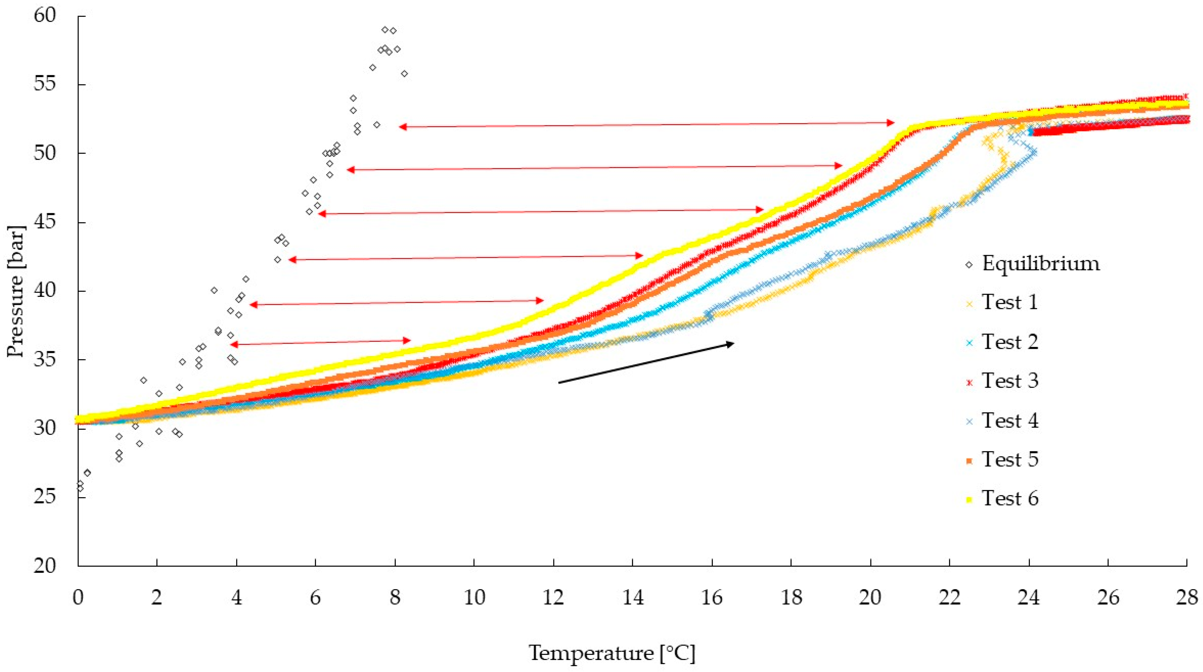
Figure 1. Phase boundary equilibrium conditions of methane [48,49,50,51], carbon dioxide [52,53,54,55], and propane hydrates [56,57].
Energies 17 01104 g001
Figure 2. Scheme of the experimental apparatus and pictures of its main details: (A) upper flange and positioning of pressure and temperature sensors; (B) connection of the reactor with gas cylinders; (C) gas ejection channel; and (D) whole apparatus.
Energies 17 01104 g002
Figure 3. Drop of temperature observed during the hydrate formation phase in each test. The internal gradient was kept close to approximately 0.2 °C/h.
Energies 17 01104 g003
Figure 4. Formation of CH4/C3H8 hydrates in tests 1–6 and comparison with the phase boundary conditions for pure methane hydrates [48,49,50,51].
Energies 17 01104 g004
Figure 5. Comparison between the phase equilibrium of pure methane hydrates and the dissociation of CH4/C3H8 hydrates observed during the experiments.
Energies 17 01104 g005
Figure 6. Gas consumed for the production of hydrates, shown as a function of time and temperature.
Energies 17 01104 g006
Figure 7. Hydrate formation rate, calculated by considering the hydrate formation process as a first-order chemical kinetic equation for the time dependence [65,66].
Energies 17 01104 g007
Table 1. Pressure–temperature values derived from the curves described in Figure 4 and comparison between the phase equilibrium conditions for pure methane hydrates and the experimental values achieved with the CH4/C3H8 gaseous mixture tested in this study (from tests 1–6).
Temperature
[°C]
Equilibrium Pressure
[bar]
Experimental Pressure
[bar]
Promotion Measured
[bar]
4.940.8133.787.03
5.243.4734.279.20
5.545.2335.369.87
5.845.8236.868.96
6.146.9037.958.95
6.448.8739.089.79
6.751.3340.2111.12
7.051.6940.9610.73
7.355.7441.7813.96
7.657.5942.4515.14
7.957.8343.1614.67
8.259.3843.8415.54
8.560.7244.5216.20
8.861.3044.9216.38
9.164.2345.3318.90
9.465.1145.6919.42
Disclaimer/Publisher’s Note: The statements, opinions and data contained in all publications are solely those of the individual author(s) and contributor(s) and not of MDPI and/or the editor(s). MDPI and/or the editor(s) disclaim responsibility for any injury to people or property resulting from any ideas, methods, instructions or products referred to in the content.

