Abstract
A three-phase multilevel inverter (MLI), synthesized with 31 levels in regard to its output voltage, is used to provide the AC supply to a three-phase, squirrel cage induction motor. The gating angles required for the 30 power switches on the MLI are optimized using both the genetic algorithm (GA) and the grey wolf optimizer (GWO), in which the optimal angles are determined through solving the trigonometric equations taken from Fourier analysis to target the minimum total harmonic distortion (THD) at the MLI output. A simulation model and an experimental prototype are developed for performance analysis and validation. The results demonstrate that the MLI is effectively able to produce 31 levels of three-phase AC output voltage, with the THD not exceeding 5% when loaded with a resistive load and a three-phase induction motor. The voltage and current are measured and recorded for different loads and operating conditions, including the amount of energy consumed by the load. The results of the frequency analysis demonstrate that most of the triple harmonics, which can harm the efficiency of the inverter, are cancelled.
1. Introduction
Three-phase multilevel inverters (MLIs) are used in applications that require a medium or high level of electrical power [1,2]. The control circuit in these inverters changes the output voltage through changing the number of levels used and the frequency of the output voltage, making them important power sources in many electrical systems. One of the main tasks in MLI applications is the need to power a three-phase induction motor, which are widely employed in numerous applications [3,4]. Recently, these inverters have been used in important applications in the field of renewable energy [5,6,7]; furthermore, they are also an essential component in the modern vehicle industry [8]. Researchers have been working hard to develop efficient controllers for inverters through enhancing the gating signals for the switches and reducing the number of switches required, to achieve the minimum amount of losses resulting from on and off states [9,10,11,12,13,14]. In this research, a three-phase MLI with 31 levels is designed, simulated, and implemented, using a Spartan 3E FPGA controller with an optocoupler, in order to drive the switches in a three-phase inverter. The genetic algorithm [15,16] and the grey wolf optimization algorithm [17,18] are employed as artificial intelligence techniques to solve and optimize the switching angles in this three-phase MLI. The remainder of this paper is organized as follows: The proposed topology of the three-phase MLI is shown in Section 2. The details of the methods employed are presented in Section 3. A MATLAB simulation analysis and its results are discussed in Section 4. A prototype and the experimental results are presented in Section 5 and, finally, the conclusions from the work are provided in Section 6.
2. Multilevel Inverter Topologies
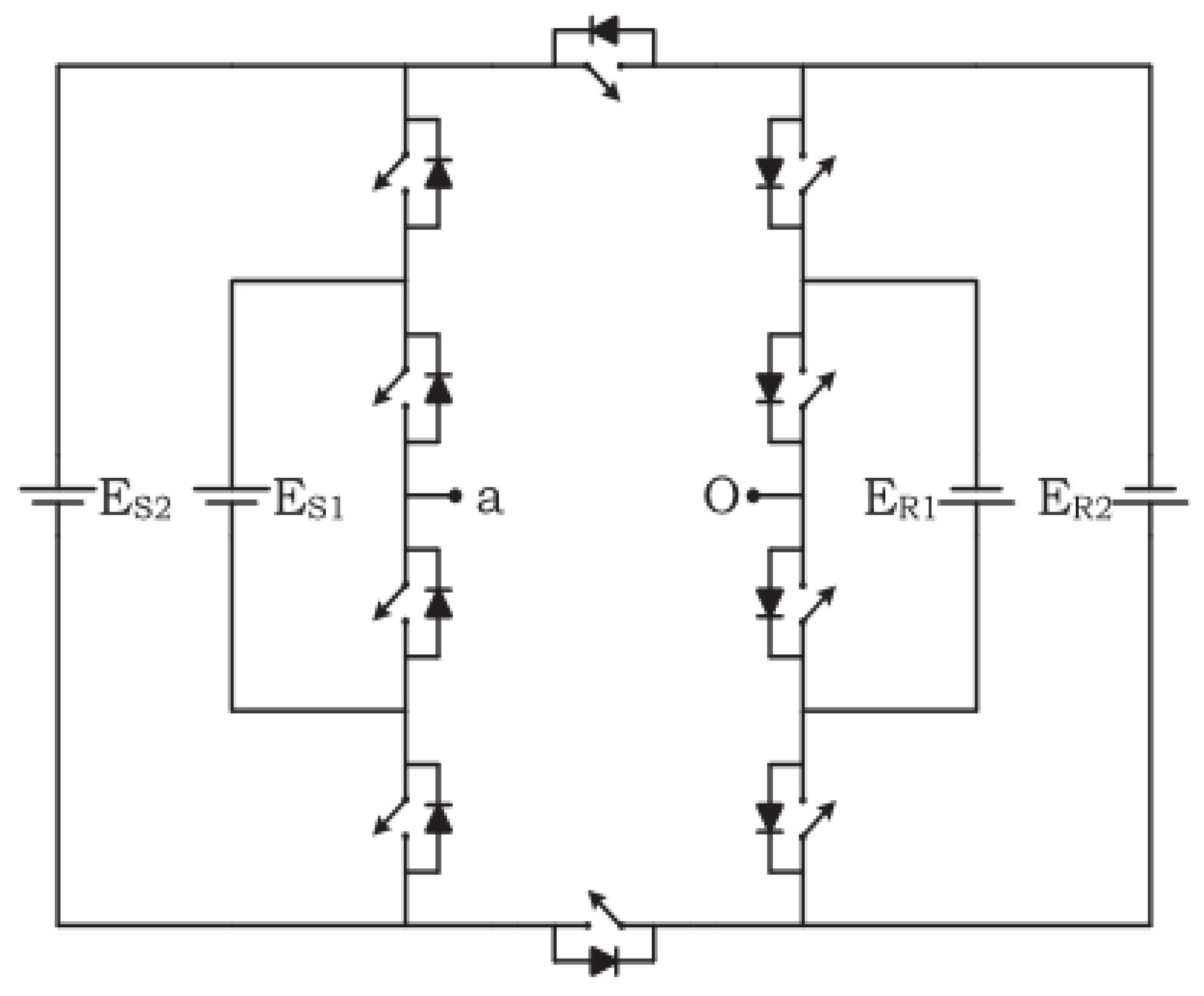
Researchers are contributing to design topologies to reduce the switch count in MLIs for better utilization of such inverters and higher efficiency. The classification of these topologies in terms of the structure and selection, for medium power inverters and for PV energy system applications, has been a valuable consideration in recent decades. A basic unit in the proposed three-phase inverter topology is based on a basic unit reported by [19], and in recent times it is known as a hexagonal switch cell (HSC), as shown in Figure 1. An extended HSC unit with four DC sources, as reported by [20], is shown in Figure 2. The topology has the merits of a simplified structure. The maximum output voltage is (ES2 + ER2) and the minimum output voltage is −(ES2 + ER2). This topology can easily be extended to include a higher number of levels. It only requires unidirectional switches. ES1 and ER1 cannot be switched on together as an addition or subtraction. The same applies to ES2 and ER2. By selecting ES1 = Vdc, ES2 = 5Vdc, ER1 = 2Vdc, and ER2 = 10Vdc, a 31-level output voltage can be produced.
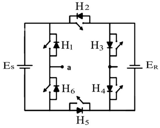
Figure 1.
Basic unit in the inverter structure.
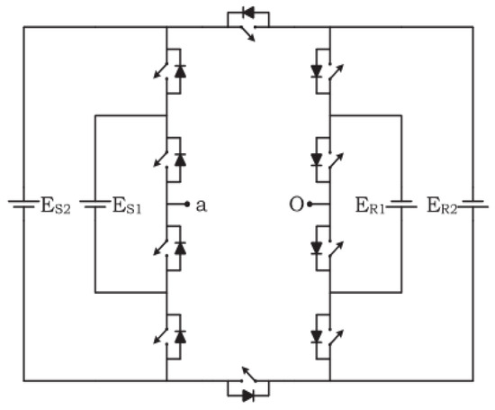
Figure 2.
Extended HSC unit.
A comparison of different basic units in a cascaded connection is shown in Table 1, in terms of the number of levels, number of switches, number of DC sources, number of phases (single or three-phase inverter), and advantages and disadvantages.

Table 1.
Basic units in a cascaded connection.
The proposed topology for the three-phase MLI with a reduced number of switches consists of 10 switches (MOSFETs or IGBTs) and 4 DC sources for each single phase, resulting in a total of 30 switches and 12 DC sources for the three-phase implementation, as shown in Figure 3.
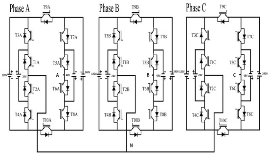
Figure 3.
Proposed topology of the three-phase, 31-level MLI.
To illustrate the principle of fabricating the multilevel inverter output, Figure 4 presents the output voltage of a nine-level inverter with four angles (. These angles are determined by solving trigonometric equations resulting from a Fourier analysis of the output voltage of the inverter. The Fourier series of a staircase periodic function can be expressed [24] as follows:
where is the average value of the output voltage, and and are even and odd components of the periodic staircase signal, respectively. The staircase waveform possesses a quarter wave symmetry, which sets the and the even values to zero, and simplifies Equation (1) to the following:
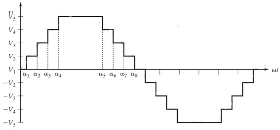
Figure 4.
A nine-level inverter and its timing instants.
These equations can be solved for any number of levels in the MLI. In a three-phase system, the triple harmonics (3rd, 9th, 15th …) are eliminated implicitly. To eliminate other harmonics (e.g., the 5th, 7th, 9th, and 11th harmonics), the following equations are solved for the optimum values of the gating angles:
where is the fundamental output voltage. Intelligent algorithms are employed to find the optimal solution for the values of these angles, relying on the selective harmonic elimination (SHE) technique with the restriction . The other timing instants for one complete cycle of the output voltage are derived from these two angles.
3. Artificial Intelligence Algorithms
Artificial intelligence (AI) algorithms work efficiently to solve mathematical problems, resulting in an improvement in the performance of engineering systems [25]. In this research, the genetic algorithm (GA) and the grey wolf optimization (GWO) algorithm are used to find the optimum switching angles for the inverter. A curve fitting principle is employed to determine the optimum solution between these two algorithms. For a three-phase inverter system with 31 levels, 15 angles are required for Phase A, and phase shifts of are set for Phase B and Phase C, respectively. The inverter is operated at a modulation index of M = 0.7. Other values in the modulation index can be implemented following the same principle, which are summarized in Table 2.
Table 2.
Switching angles for a 31-level inverter.
4. Results
4.1. Simulation Results
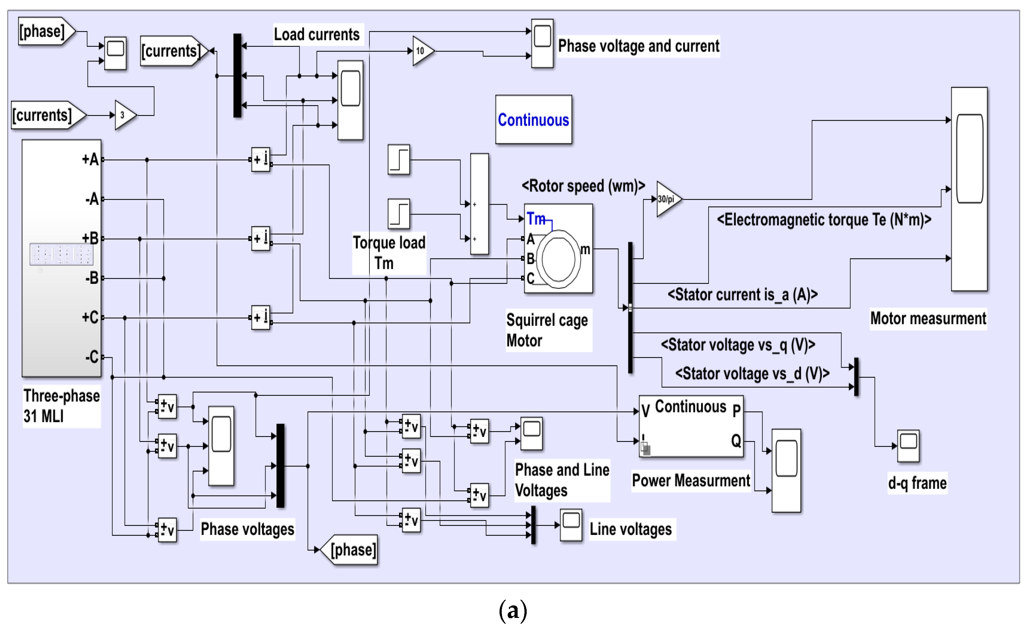
The proposed three-phase, 31-level MLI was built and simulated using the MATLAB Simulink software version R2019a, using the optimized angles provided in Table 1. The three single-phase inverters are Y-connected to form a three-phase 50 Hz AC supply source, as shown in Figure 3. Each phase has 10 power switches (IGBTs) and 4 DC sources. The IGBTs work in complementary mode. Switches T2, T4, T6, T8, and T10 complement T1, T3, T5, T7, and T9, respectively. A voltage of VDC = 24 V is used for each staircase level. The other three DC sources are 2VDC = 48 V, 5VDC = 120 V, and 10VDC = 240 V. To generate 31 levels in the inverter output voltage, multiple paths are chosen for the electrical current to pass through the power switches. Here, several DC sources are used; either adding them together, subtracting them from each other, or using individual sources. The peak output phase voltage = 15 (level) × 24 V (one staircase voltage) = 360 V. The peak line voltage = 580 V and VL(RMS) = 410 V. The three-phase induction motor specifications used for the simulation are as follows: squirrel cage (5.4 HP, 4 KW, 50 Hz, 1430 RPM). The Simulink model of the 31-level, three-phase MLI connected to a three-phase squirrel cage induction motor load is shown in Figure 5a. The block diagram consists of three main circuits, each of which has devices attached to measure the voltage, current, and other variables.
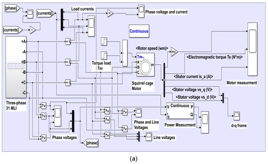
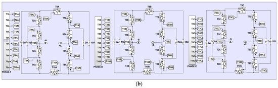
Figure 5.
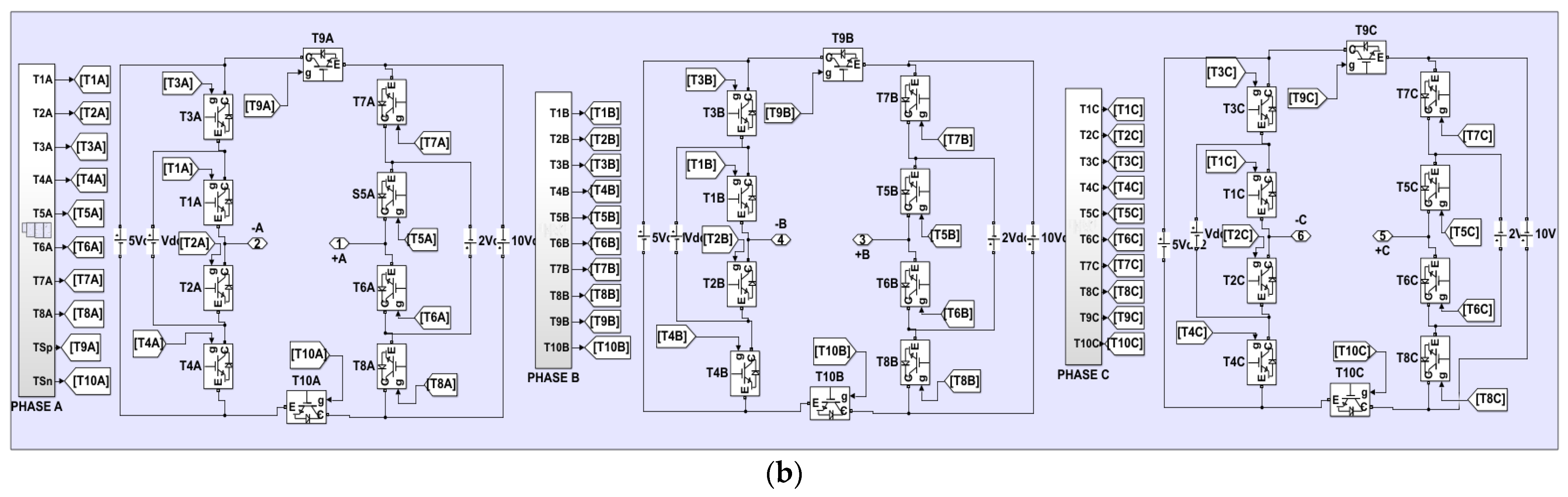
(a) Simulink model of the 31-level, three-phase MLI connected to a three-phase motor. (b) Simulink model of the three-phase, 31-level MLI showing the gating signals.
The first circuit is a three-phase inverter, as shown in Figure 5b, which consists of a three star-connected single-phase inverter. There are 30 insulated gate bipolar transistors (IGBTs) with diodes and 12 DC sources. The output terminals of the three-phase inverter are points (+A, +B, and +C), while points (−A, −B, and −C) are connected to form the neutral point in the star connection.
The second circuit involves the operation of the switches based on artificial intelligence algorithms and will be detailed later. The load circuit is the third part and consists of a static load represented by a different set of resistors and a dynamic load represented by a three-phase squirrel cage induction motor. The detailed fabrication of the gating periods in Phase A is shown in Table 3; the asterisk (*) represents the complementary mode.
Table 3.
Switch state for the positive half period.
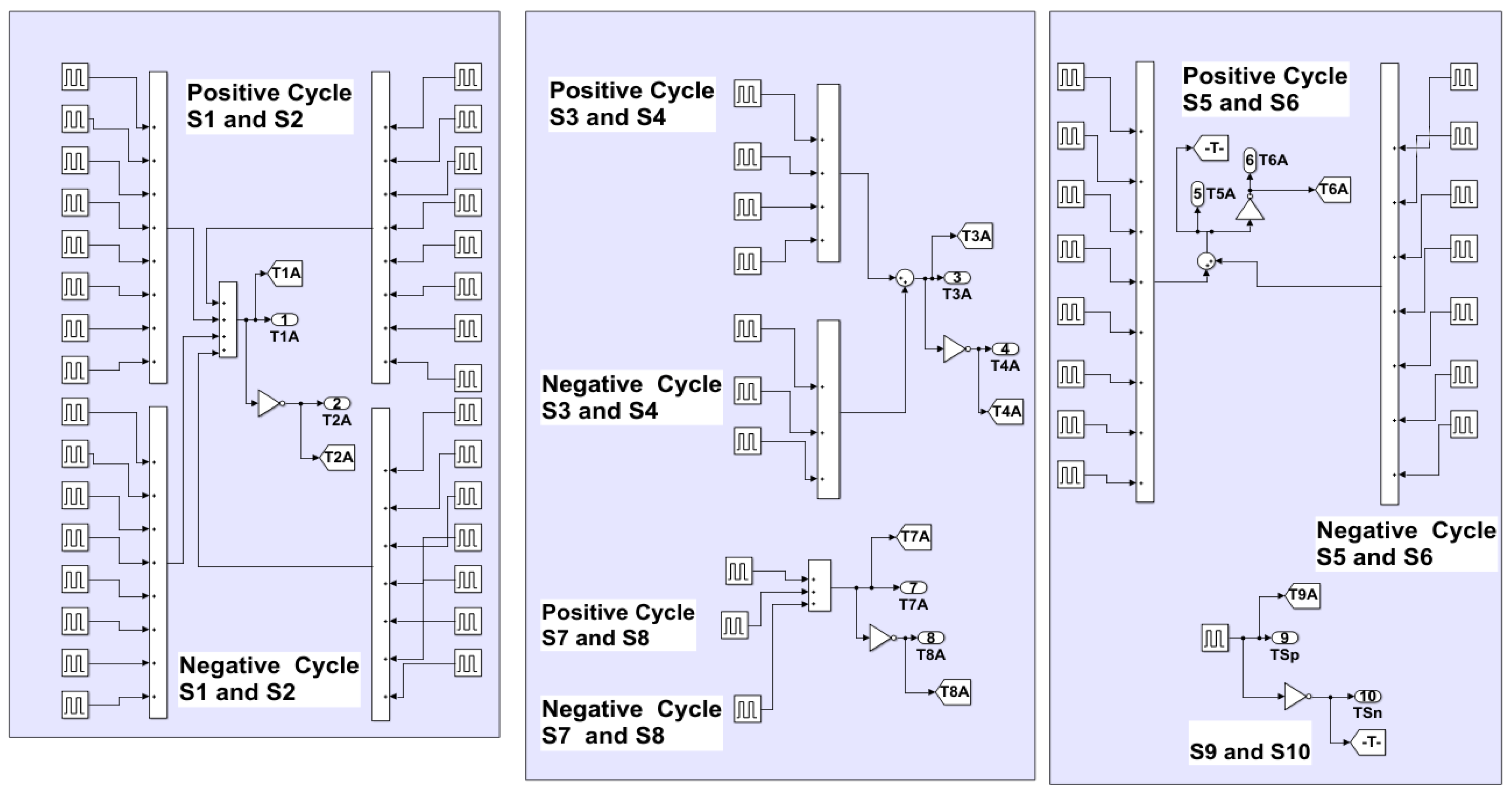
A detailed Simulink model of the switching controls is shown in Figure 6. The gating signals for phases B and C are derived from Phase A, by adding phase shifts of and , respectively.
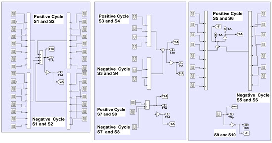
Figure 6.
Fabrication of the gating periods for Phase A.
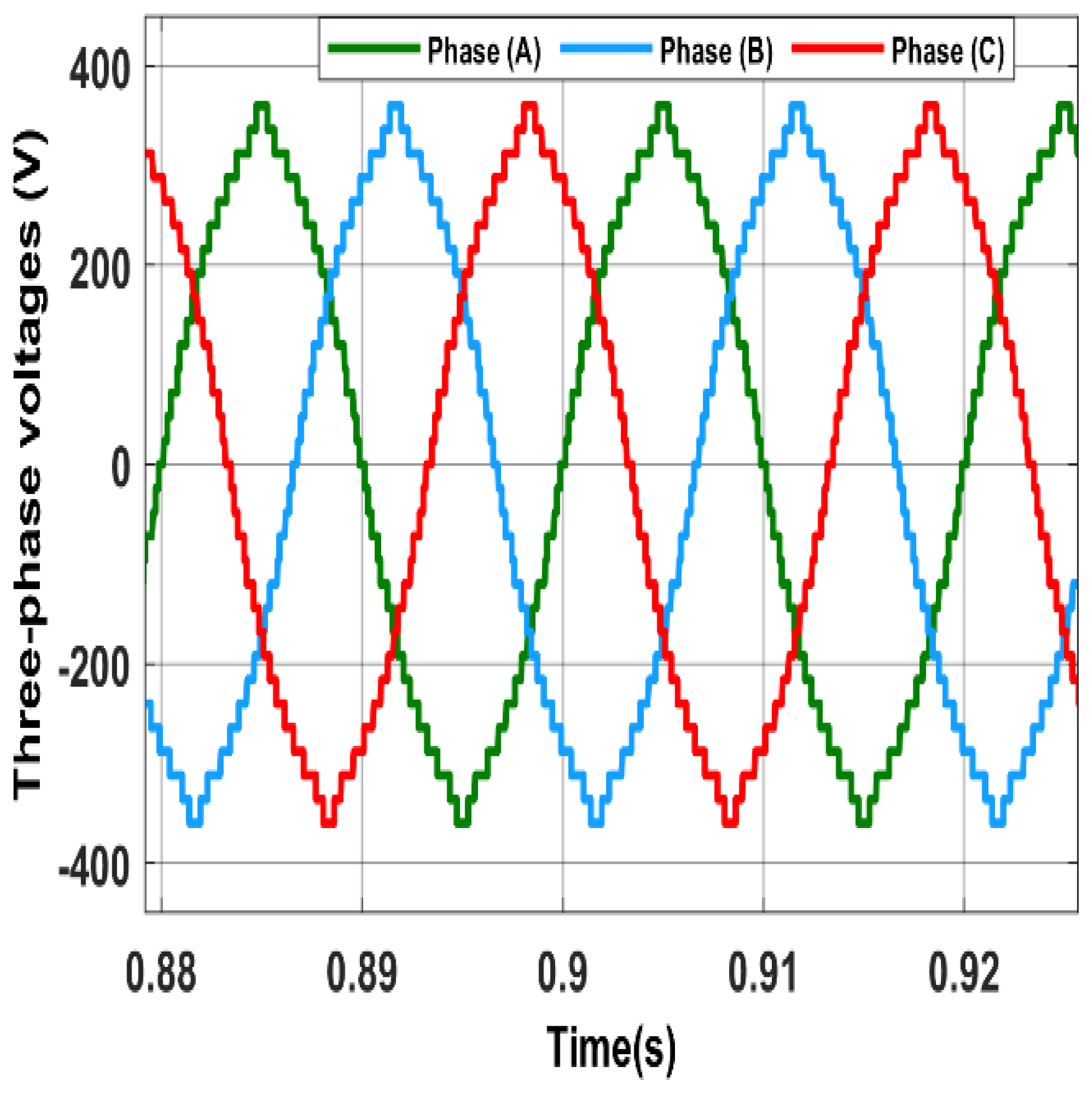
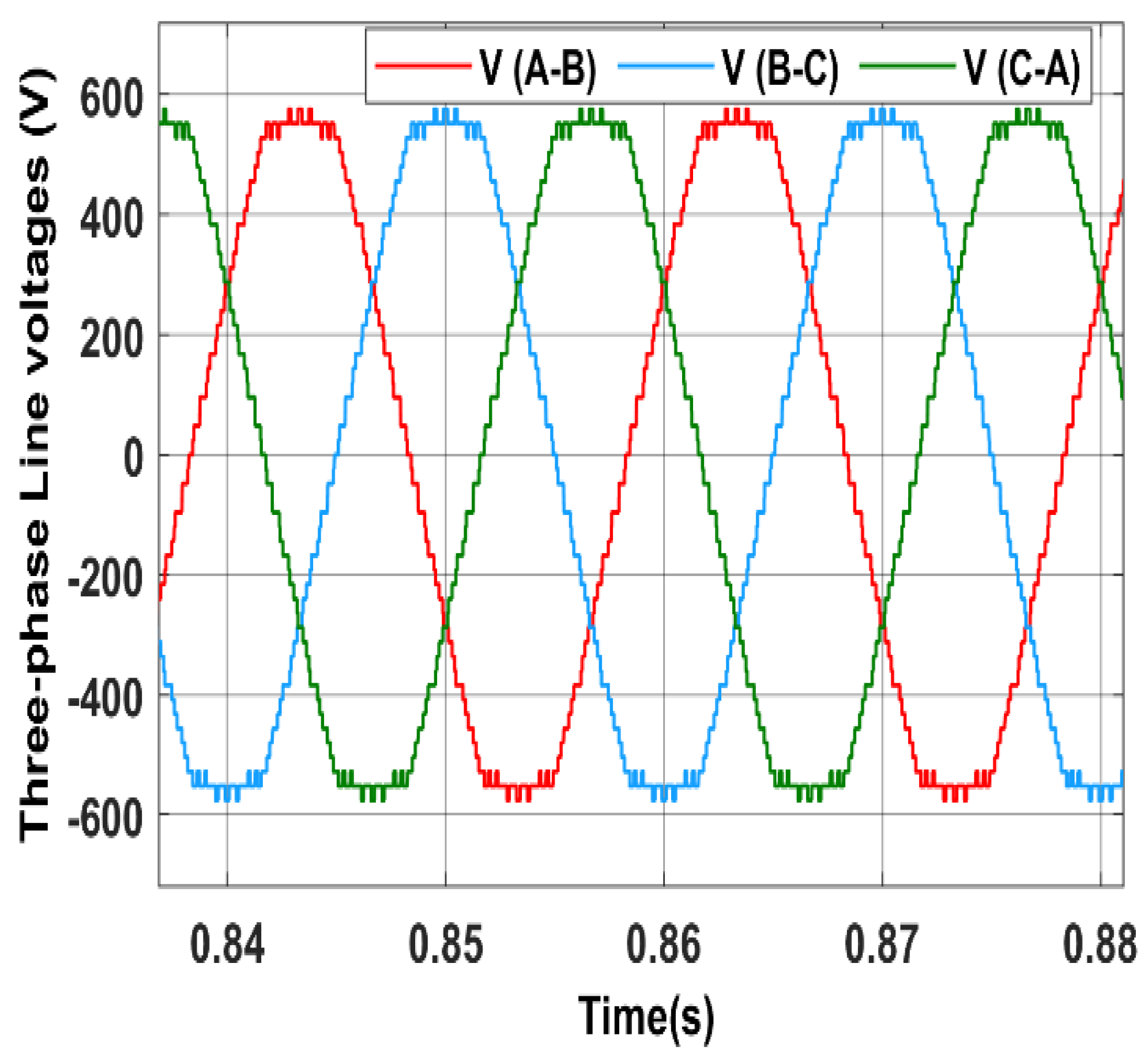
The three-phase output and line voltages for the 31-level MLI are shown in Figure 7 and Figure 8, respectively.

Figure 7.
Phase voltages from the simulation.
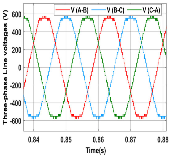
Figure 8.
Line voltages from the simulation.
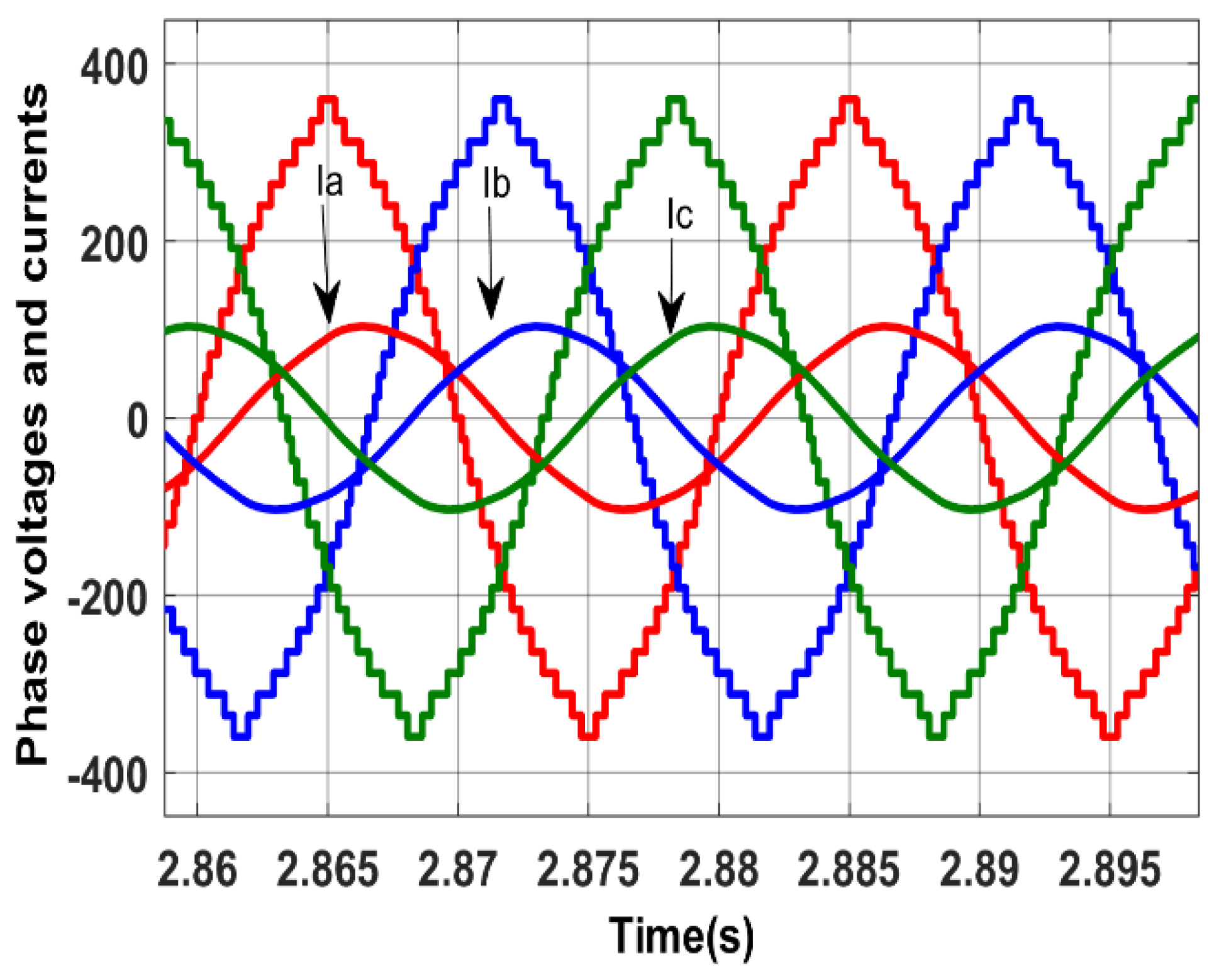
The phase currents supplied by the 31-level MLI to the induction motor are shown in Figure 9. The current from 0 to 1 sec is about 4.25 A (rms) when the motor is operating at no load. When the motor is subjected to an external 20 Nm load at an instance from 1 s to 2 s, the current increases to 11.3 A (rms). Finally, from 2 s to 3 s, the current increases to about 24 A (rms), when the motor is subjected to a 40 Nm load. Figure 10 shows a phase shift of about 36° between the supply voltage and the current, indicating a lagging power factor of 0.81.
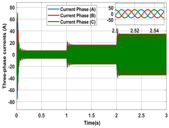
Figure 9.
Squirrel cage motor currents.
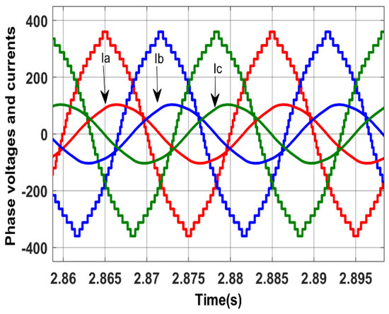
Figure 10.
Phase shift between the voltages and currents.
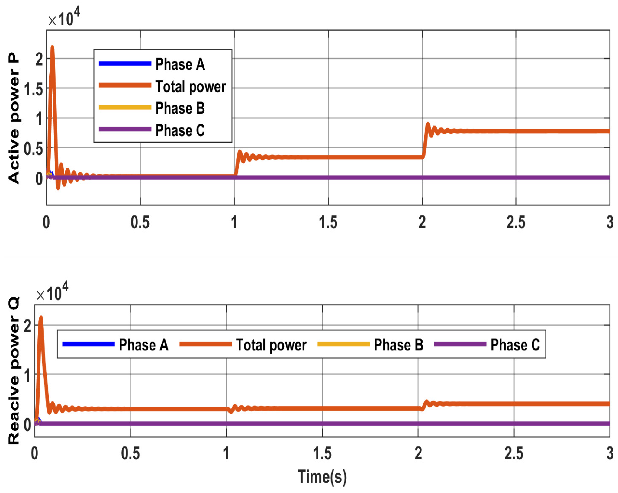
Figure 11 shows the measurements for the three-phase squirrel cage induction motor, consisting of the motor speed, electromagnetic torque, and stator current. The motor reaches the base speed of about 1500 rpm at no load. This speed is then reduced because of the external load applied at an instance between 1 s and 2 s. The stator current increases from no load to higher values to reflect the load torque applied. The power consumed consists of active power, P, and reactive power, Q, as shown in Figure 12.
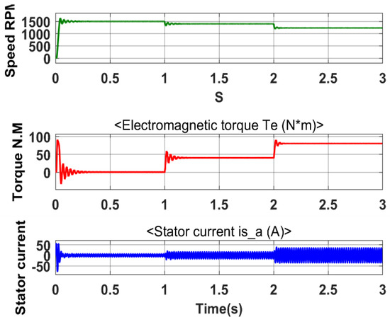
Figure 11.
Motor measurements at different loads.
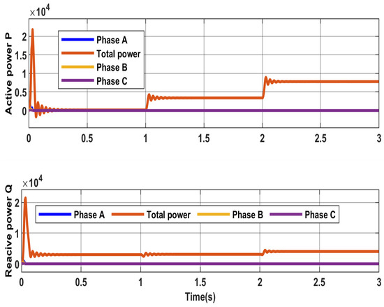
Figure 12.
Power consumed by the load.
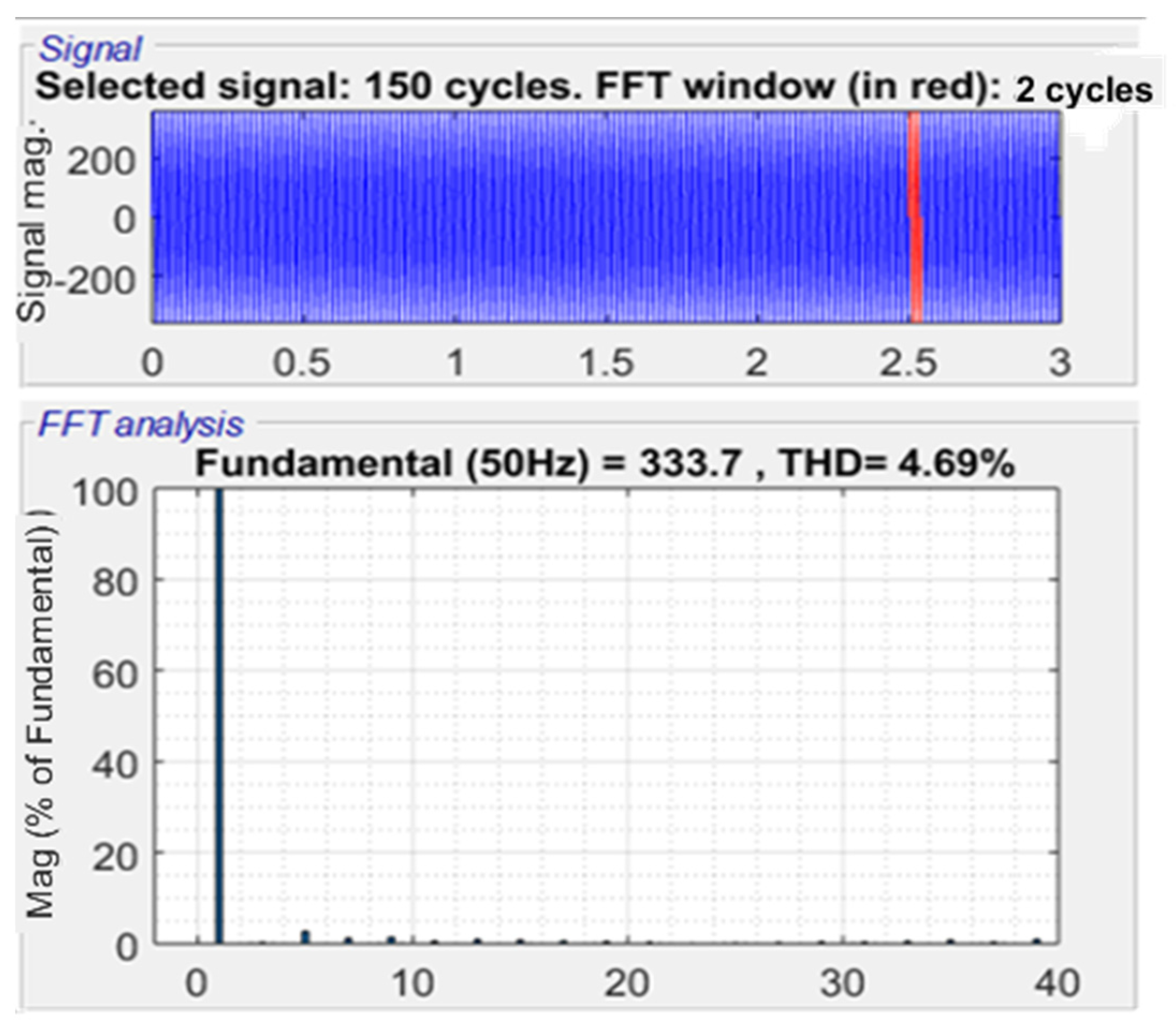
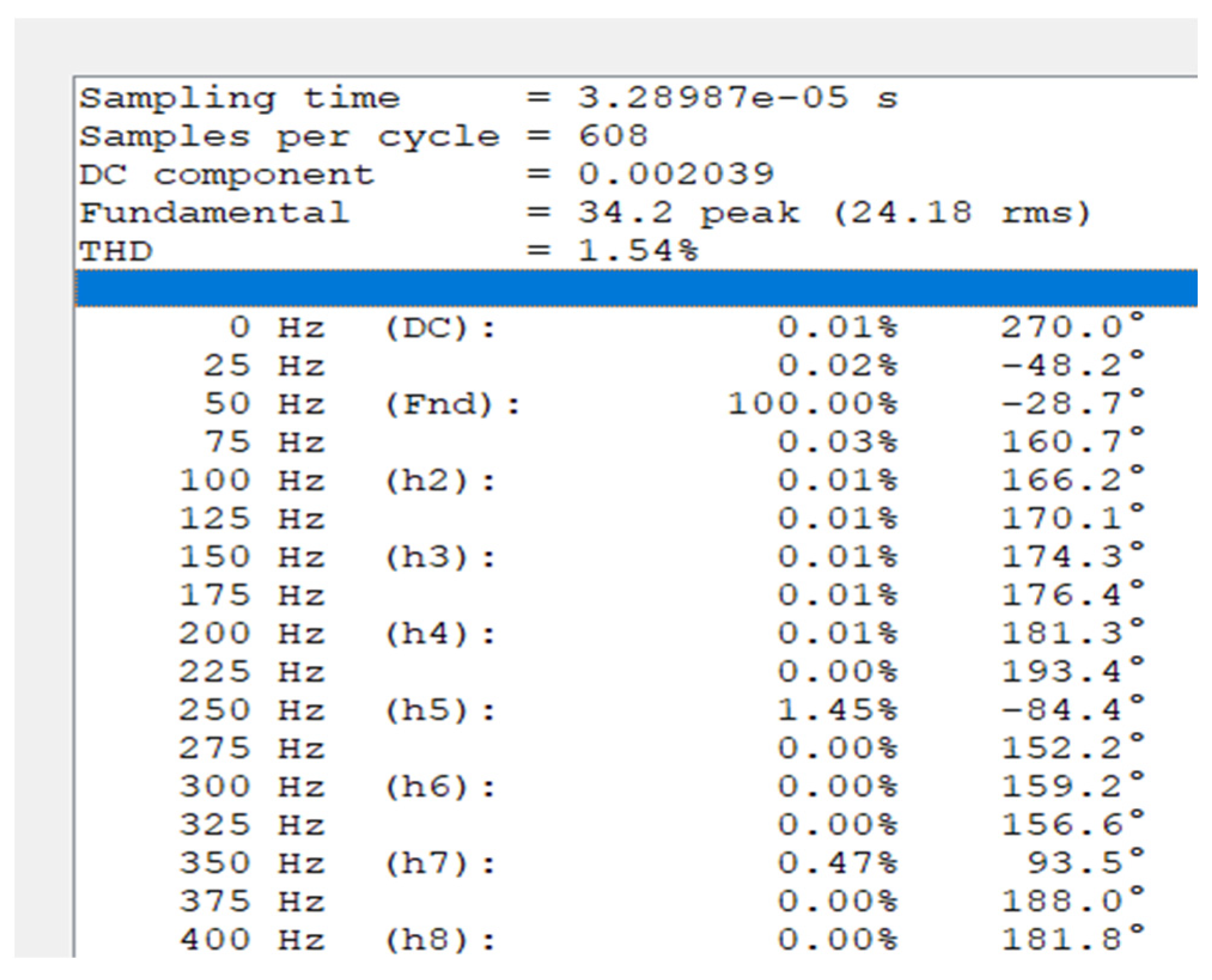
The fast Fourier transform toolbox in the MATLAB software revealed that the harmonic content in the inverter’s phase voltage is relatively low; the total harmonic distortion THD is about 4.69%, and the recorded value of the line voltage THD is 4.05%, as shown in Figure 13 and Figure 14, respectively. The motor is considered to be an inductive load that filters some harmonics, resulting in a low harmonic distortion THD of 1.54% for the motor current, as shown in Figure 15. Figure 16 shows values for the DC component = 0.002039 and some of the harmonic contents, which have low values compared to the fundamental 50 Hz component.

Figure 13.
Phase voltage.
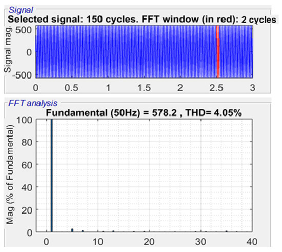
Figure 14.
Line voltage harmonic content.
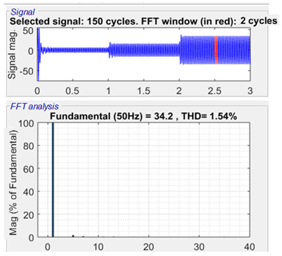
Figure 15.
Current harmonic content.
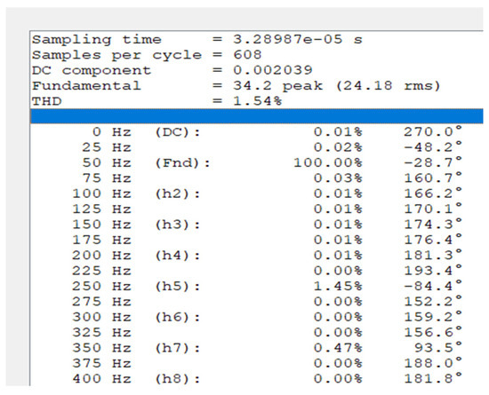
Figure 16.
List of harmonics content in inverter current.
4.2. Practical Results
4.2.1. Generating Gating Pulses
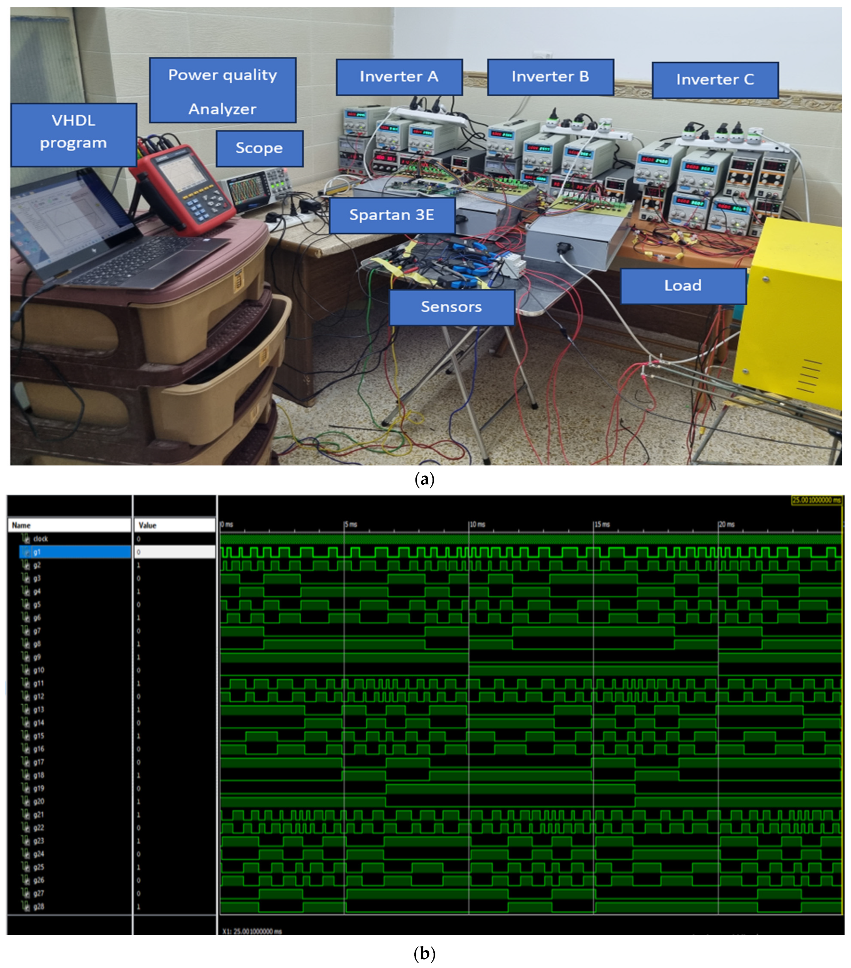
The Spartan 3E controller is used as the processor unit in the experiment. The clock frequency of the controller is 50 MHz; therefore, the period of each clock is 20 ns. To cover one 50 Hz AC supply cycle at the inverter output, a total of 20 ms/20 ns = 1,000,000 clocks linked to the Spartan 3E controller are required. A prototype of the proposed three-phase, 31-level MLI is designed and built, as shown in Figure 17a. The operation of 30 switches is programmed using the Spartan 3E controller through writing a program in the VHDL language, then running a simulation such that the appropriate pulses can operate the switches. The simulated pulses for one cycle of operation are shown in Figure 17b.
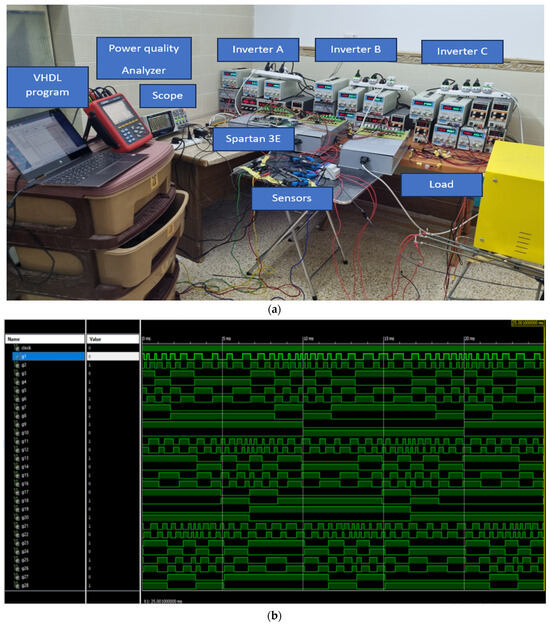
Figure 17.
(a) Experimental set up for the implementation of the proposed three-phase, 31-level MLI. (b) Spartan 3E simulated pulses for the IGBTs.
The corresponding number of pulses for each optimized angle, as shown in Table 1, is provided in Table 4.
Table 4.
Corresponding pulse counts by the Spartan 3E clocks for the 15 angles.
Table 5 details the IGBT states for the positive half cycle of Phase A. The IGBT states for phases B and C are determined by considering a 120° phase shift between the three phases. The asterisk (*) represents the complementary mode.
Table 5.
IGBT states for the positive half cycle of phase A.
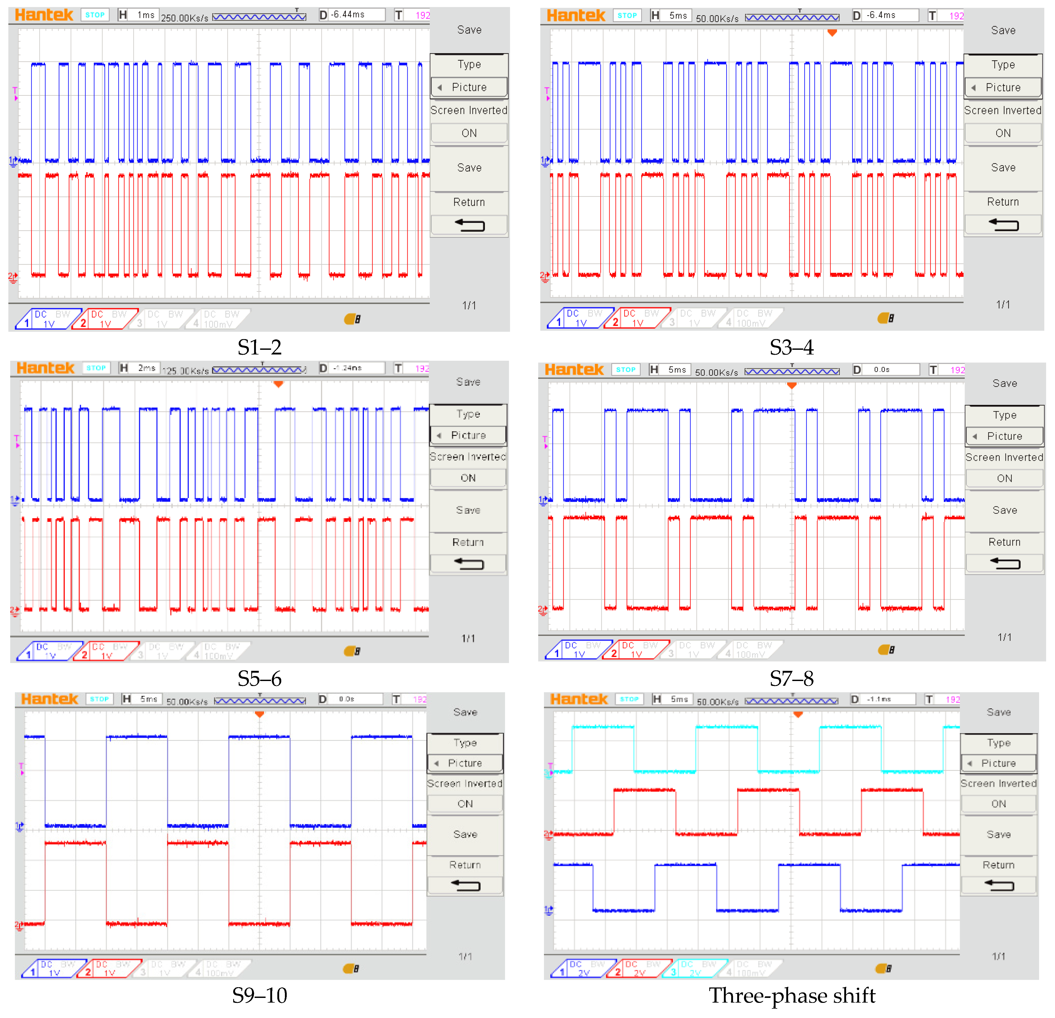
A VHDL file, based on the data in Table 4, used to obtain the 31-level MLI is uploaded to the Spartan 3E controller. The controller outputs 30 gating signals. These gating signals are fed to the 30 appropriate power switches. The 10 power switches in each phase’s circuitry are designed to work in complementary mode, as shown in Figure 18 for Phase A. Also shown are the 120° phase shifts between phases A, B, and C. A dead time of 4 µsec is added between the outgoing and incoming switches, in order to avoid all possible short circuits.
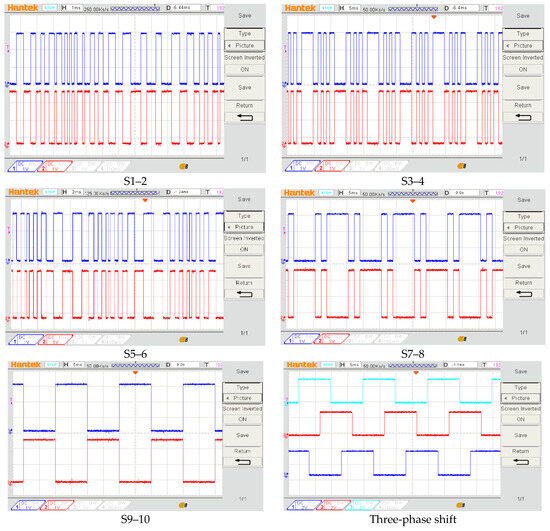
Figure 18.
Gating pulses for the IGBTs in Phase A and the phase shift between phases.
4.2.2. The Proposed 31-Level MLI Operating at No Load
The system is operated at no load to monitor the phase and line voltage. Figure 19a shows the three-phase output voltage at 50 Hz and 122 Vrms. The line voltage (Vab) is shown in Figure 19b at 50 Hz and 210 Vrms.
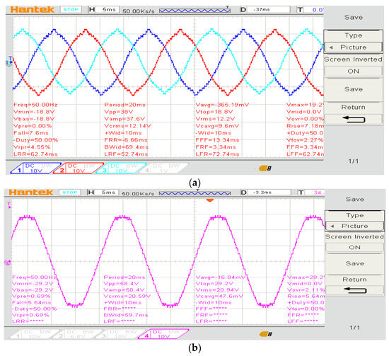
Figure 19.
Phase and line voltage of the proposed three-phase, 31-level MLI at no load. (a) Phase voltage (scale ×10), (b) line voltage (Vab) (scale ×10).
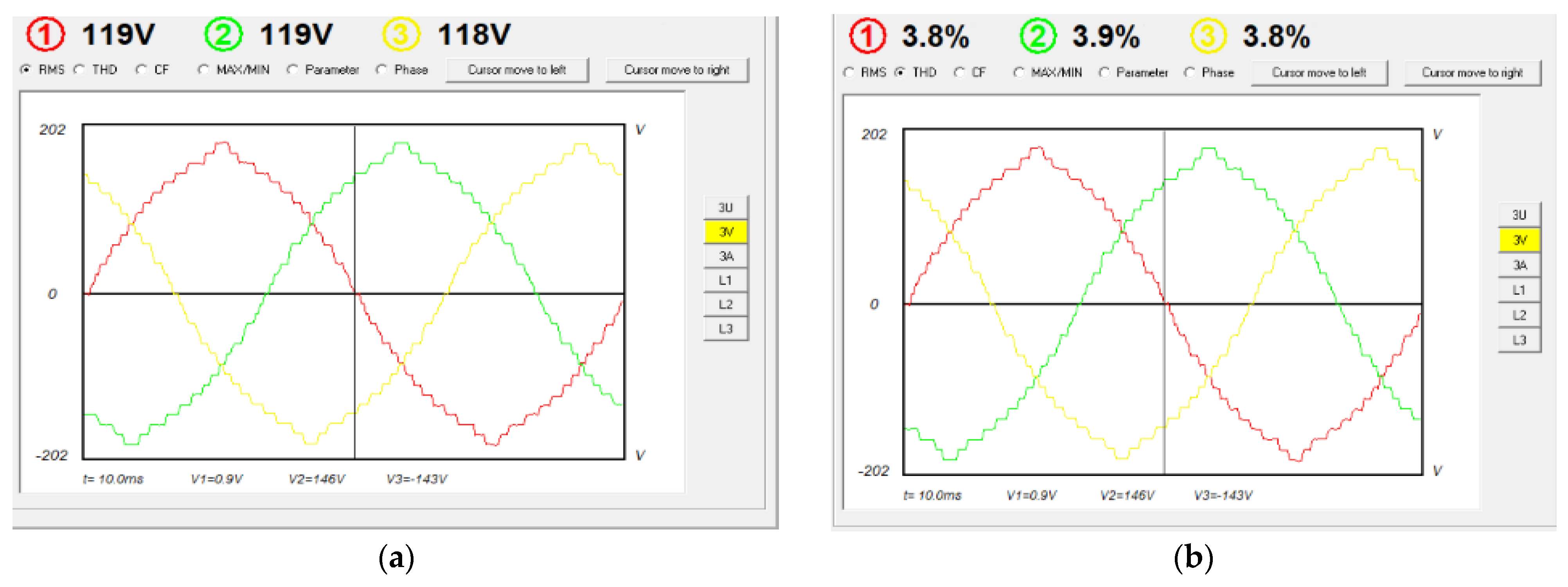
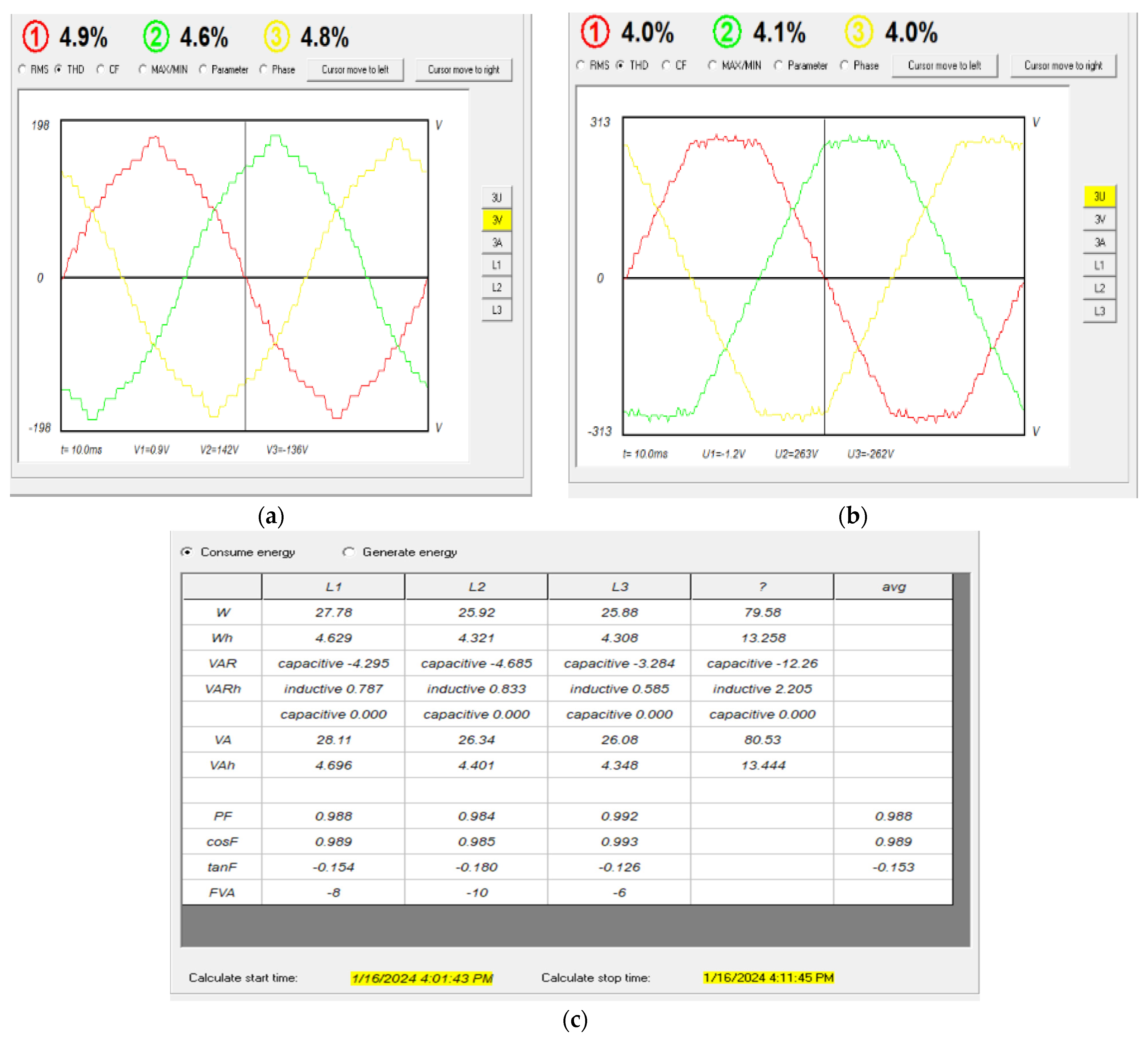
The power and quality analyzer HZCR-5000 is used to record the results. The three-phase voltage, THDs, and phase shift between the phases are shown in Figure 20a, and Figure 20b respectively.
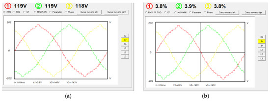
Figure 20.
The three-phase voltage and THDs at no load: (a) phase voltage, (b) phase THDs.
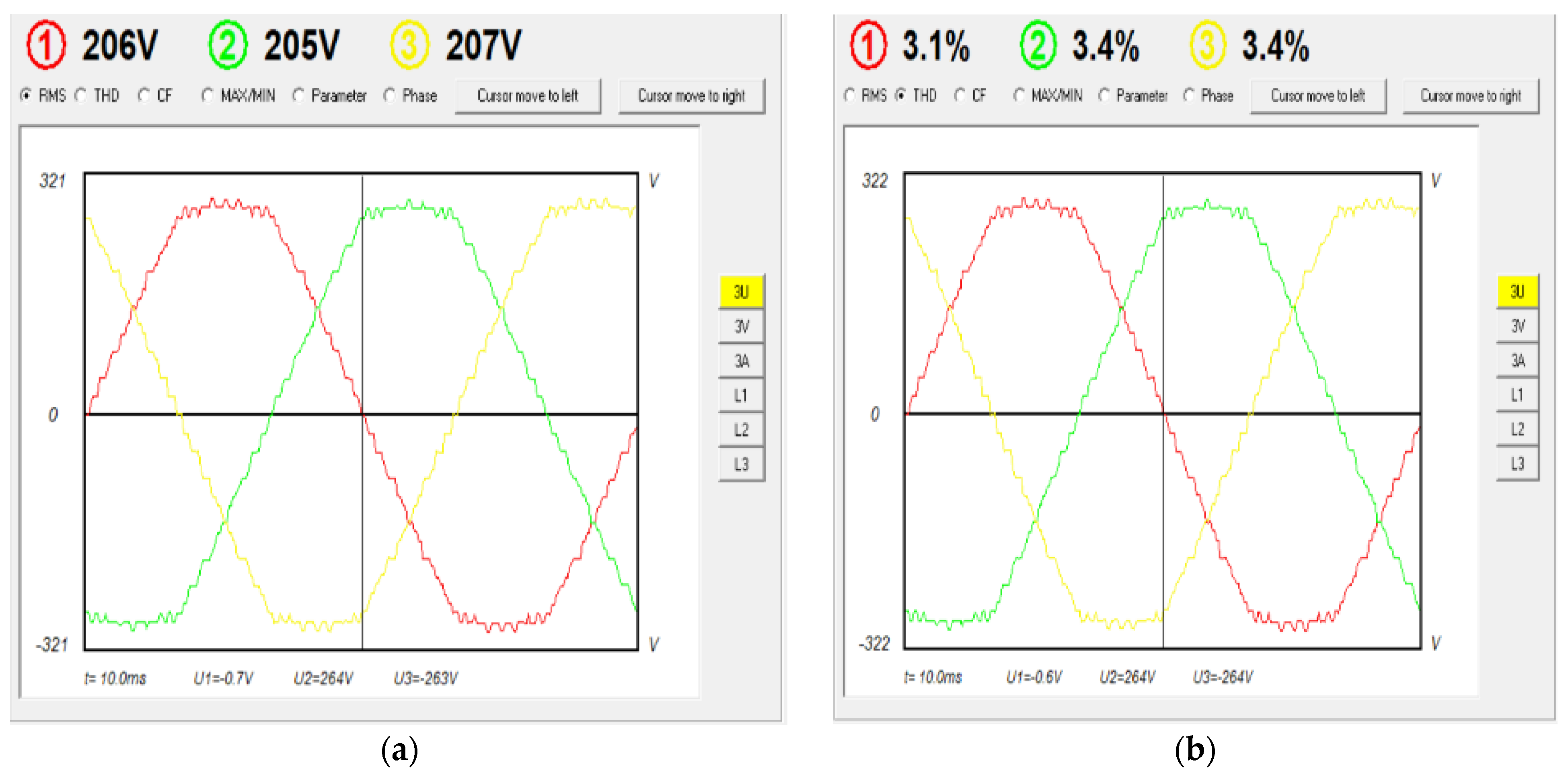
The line voltage, THDs, and phase shift between the phases are shown in Figure 21a, and Figure 21b respectively.
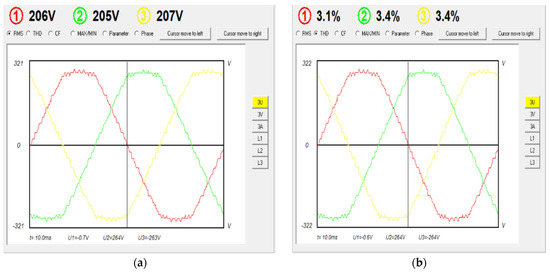
Figure 21.
Line voltage and THDs at no load: (a) line voltage, (b) line voltage THDs.
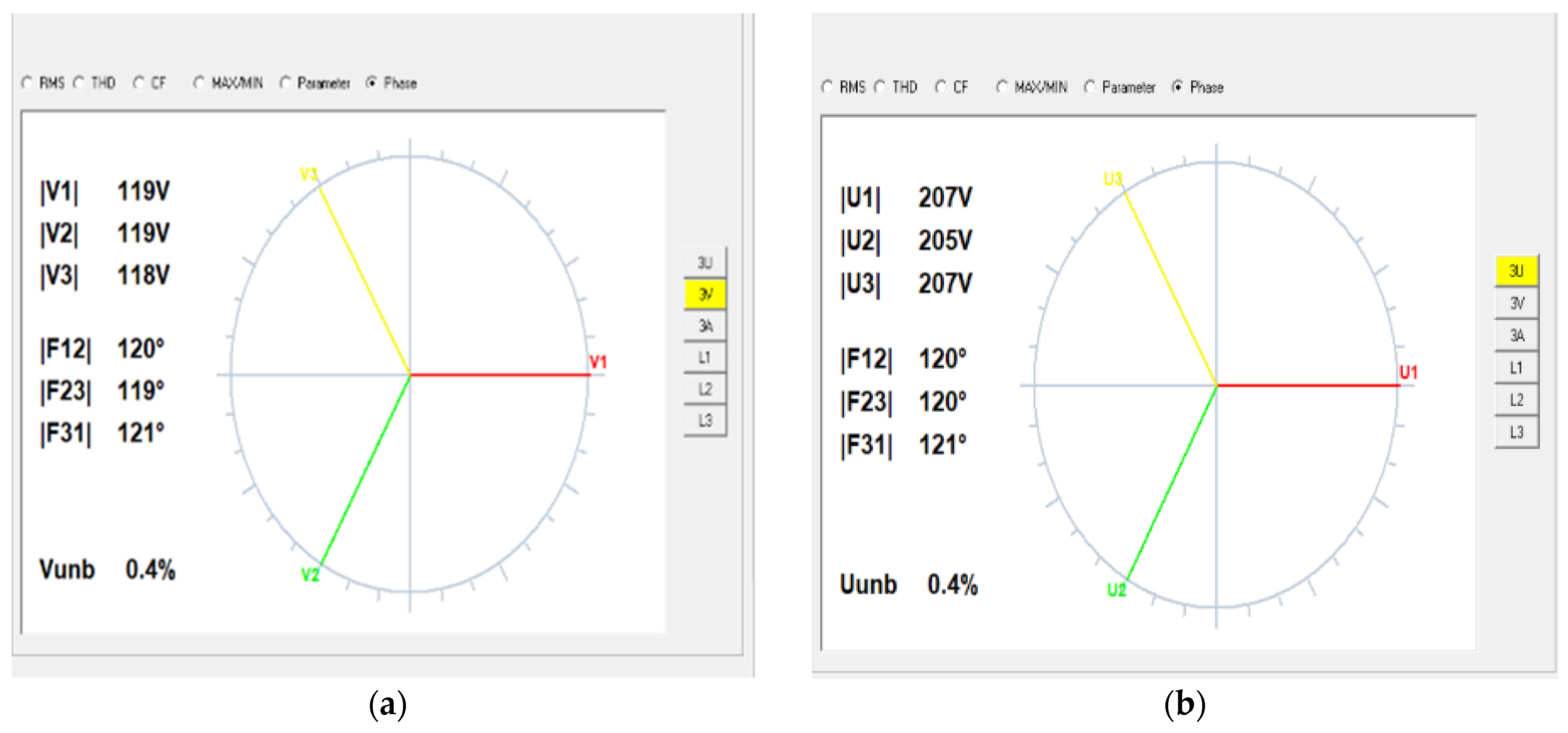
The phase shifts between the three-phase and the three-line voltage are shown in Figure 22a and Figure 22b, respectively. The voltage unbalance is very low and about 0.4%.

Figure 22.
Phase shift (a) phase voltage shift (b) line voltage shift.
4.2.3. Load Test
The load test is divided into two parts: a static load using a three-phase resistive load and a dynamic load using a three-phase squirrel cage induction motor. In the static load test, a Y-connected resistive load is connected to the output terminals of the 31-level MLI. The THD of the phase and line voltage are well below the 5% limit, as shown in Figure 23a,b, respectively. The details of the consumed power are shown in Figure 23c, where the power factor is almost at unity due to the purely resistive load.
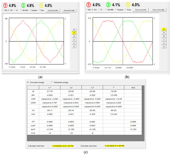
Figure 23.
Phase and line voltage values of the THDs and consumed power for a resistive load: (a) phase voltage (resistive load) THDs, (b) line voltage THDs, (c) consumed power.
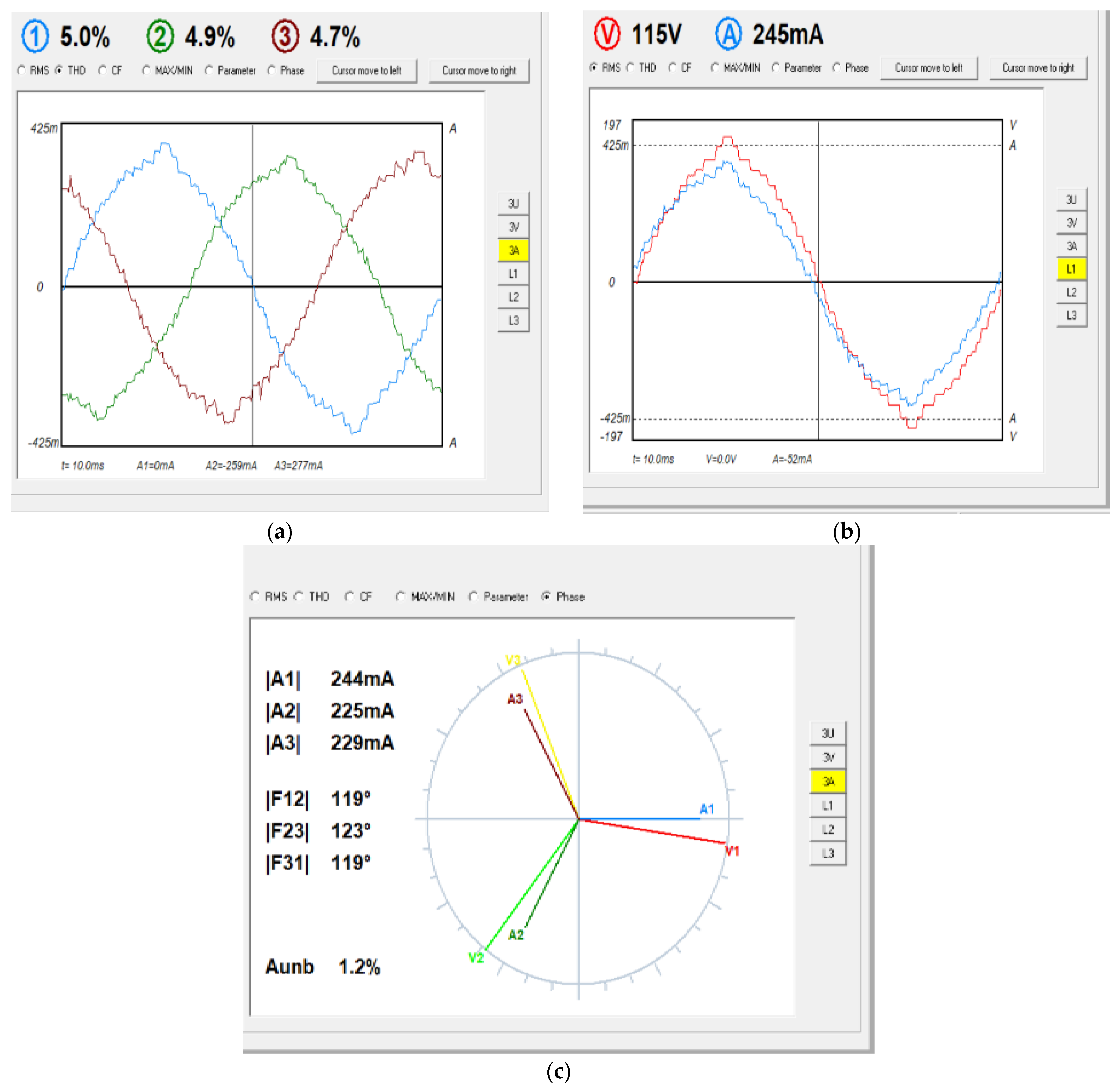
The three phase currents in Figure 24a have an average THD value below 5%, which is compatible with the respective voltage values. The relationship between the phase voltage and current in the Phase A supply is shown in Figure 24b. The other phases responded with very similar characteristics. Figure 24c shows the phase difference between the three phase currents. Although the load is resistive, there is a small value difference in the phase between the voltage and current, which is normal in practical work. The voltage unbalance is recorded as 1.2%, which is a low value.
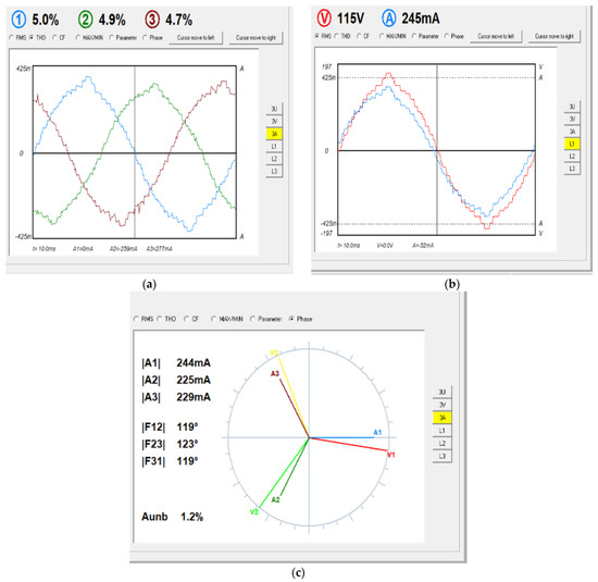
Figure 24.
Phase current results for a resistive load: (a) phase currents (THDs) for a resistive load, (b) voltage–current relationship, (c) phase shift between the phase currents.
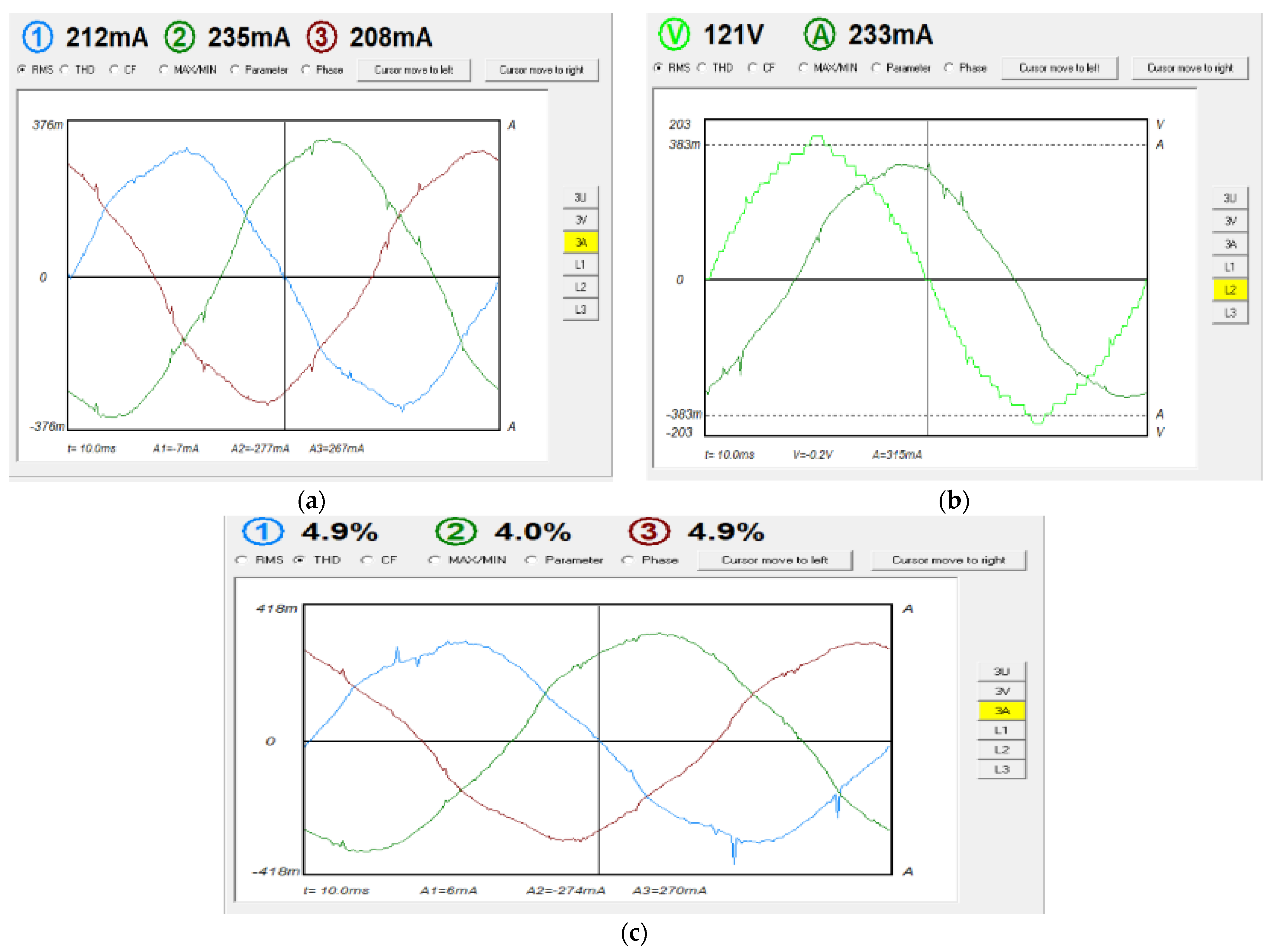
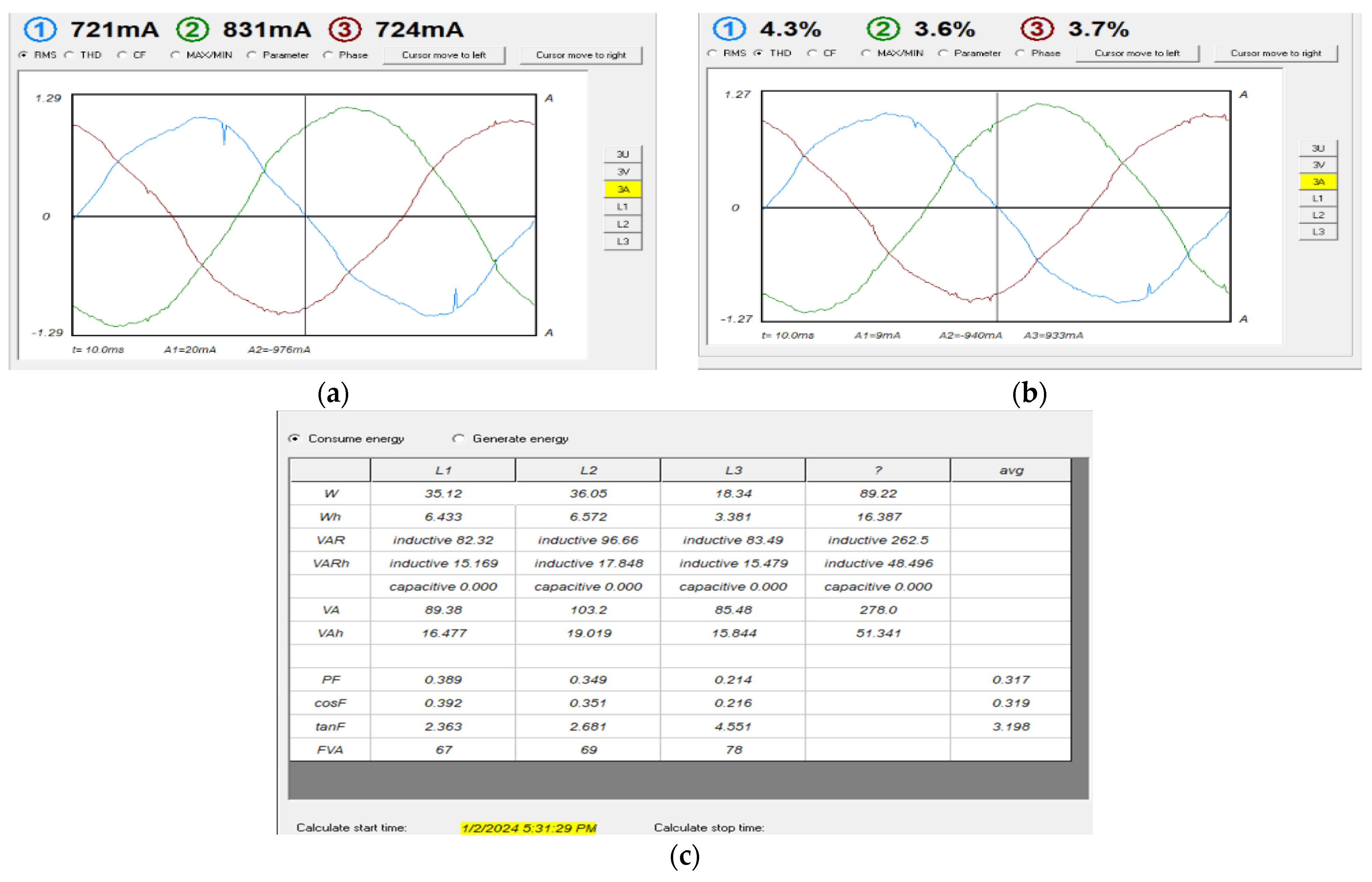
A three-phase squirrel cage motor is used in the dynamic load test. The motor has the following specifications: three-phase induction motor (SIEMENS) 220/380 Δ/Y, 0.18 kW, 1315 rpm, 50 Hz. When the motor is at no load, the 31-level MLI supplies a relatively small three-phase current of about 0.25 A per phase, as shown in Figure 25a. The relationship between phase voltage and current in phase B is shown in Figure 25b. The current can be seen to lag behind the voltage, as the load is now inductive. The recorded THDs are less than 5%, as shown in Figure 25c.
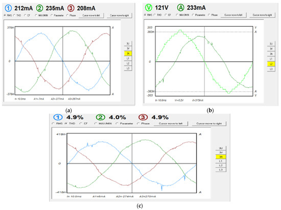
Figure 25.
Motor currents at no load: (a) phase currents, (b) voltage–current phase shift, (c) motor current THDs.
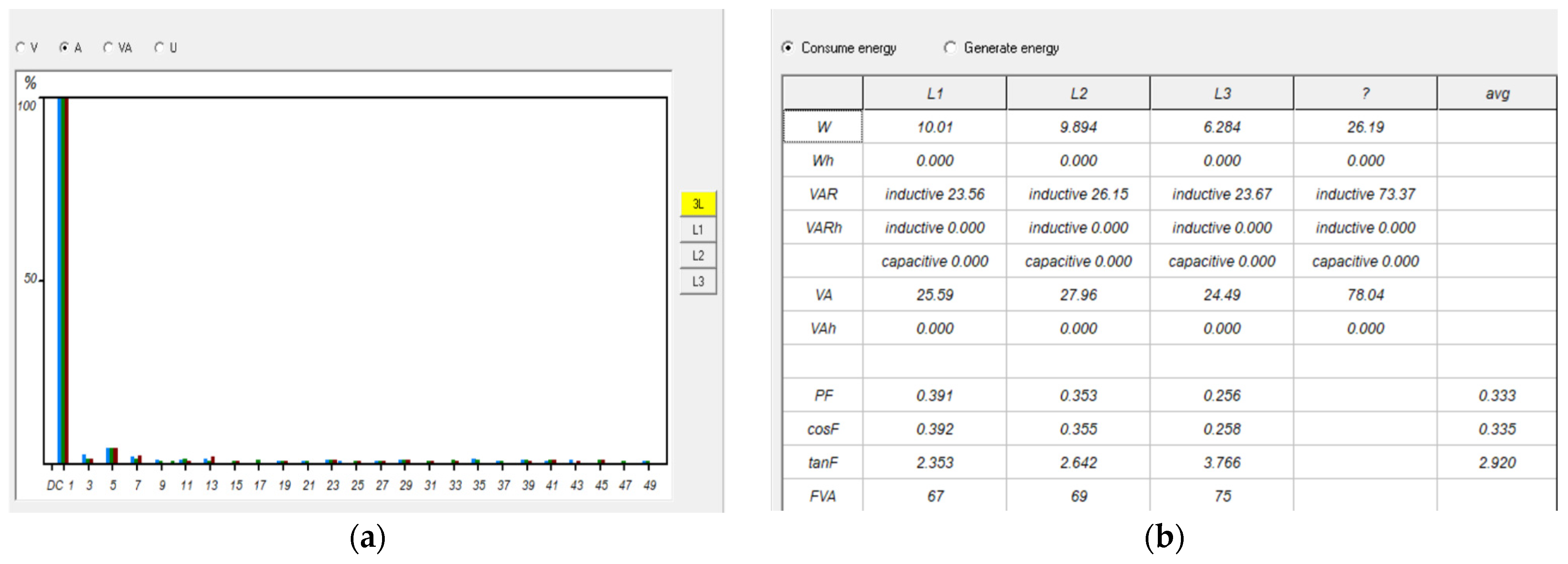
The harmonic analysis is shown in Figure 26a, Blue color for phase A, green for phase B, and grey for phase C, where most of the triple harmonics were either eliminated or exist at low values. The power consumed by the motor, as in Figure 26b, shows the effect of the inductive load on the total VAR power.
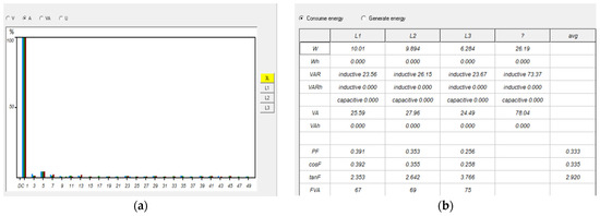
Figure 26.
Motor current harmonics and consumed power at no load: (a) harmonic analysis, (b) consumed power.
The motor is later subjected to a fan load. The 31-level MLI supplied the current at about 0.75 A per phase to the motor to compensate for the applied load torque, as shown in Figure 27a. The THDs are still low, averaging about 3.8%, as shown in Figure 27b. The power consumed by the motor at load is shown in Figure 27c.
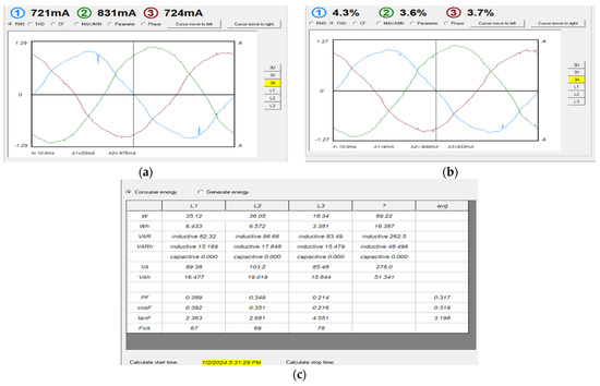
Figure 27.
Motor current, THDs, and consumed power at load: (a) motor currents, (b) motor THDs, (c) consumed power.
Using the MATLAB software, a three-phase motor was chosen with the following specifications: squirrel cage (5.4 HP (4 KW), 400 V, 50 Hz, 1430 RPM). To obtain an output voltage from the inverter of 400 volts, the value of the continuous source Vdc must be equal to 24 volts in the Simulink model. On the practical side, a three-phase delta induction motor was connected to a voltage of 210 volts, which requires a Vdc voltage of 12 volts. Here, the difference in the value of the inverter output voltage between the simulation and the practical results appeared.
5. Conclusions
A three-phase, 31-level MLI is designed, modeled, and experimentally tested, as described in this paper. The genetic algorithm and grey wolf optimization algorithm are used to solve the trigonometric equations resulting from a Fourier analysis of the inverter voltages, in order to find the ideal angles to cancel most of the triple harmonics. The optimal angles are then chosen from the ideal angles, between the two algorithms, through curve fitting. The inverter is loaded with a resistive load and a three-phase induction motor. The THD values are not in excess of 5% for all the operating conditions, for the phase and line voltages or for the load currents. The frequency analysis shows that most of the triple harmonics are eliminated. The simulation of the three-phase MLI system is investigated using the MATLAB Simulink model, and the simulation results are in good agreement with the practical results. In all the operating conditions for the different resistive loads, as well as when the induction motor is loaded, the inverter works smoothly with a stable THD value, which indicates high efficiency of the practical model. The proposed 31-level MLI system can potentially become an efficient and reliable three-phase inverter for various static and dynamic loads. Table 6 summarizes the inverter’s output regarding the phase voltage, line voltage, and current resulting from the resistive load and the induction motor. The amount of THD did not exceed 5%, on average; noting that the value of the THD is lower in regard to the inductive load compared to the resistive load, due to filtering characteristic of the inductive load.
Table 6.
Summary of the inverter output voltage and current.
6. Future Suggestions
The THD value has a fundamental impact on the efficiency and utility of an inverter. Two main factors significantly reduce the amount of FAD. First, optimal values should be used in regard to the operating angles of the power switches. This is achieved through choosing the best angles from a larger group of algorithms, which represents more algorithms than those considered in this research. Second, the number of switches used should be reduced by devising a topology that ensures smooth current pathways while, at the same time, obtaining a larger number of inverter levels and contributing to reducing the number of DC sources needed by the inverter.
Author Contributions
Conceptualization, T.A.H.; Data curation, D.I.; Formal analysis, T.A.H.; Investigation, T.A.H.; Methodology, D.I.; Project administration, D.I.; Resources, T.A.H. and M.T.; Software, T.A.H.; Supervision, D.I. and M.T.; Validation, D.I. and M.T.; Visualization, T.A.H.; Writing—original draft, T.A.H.; Writing—review and editing, D.I. and M.T. All authors have read and agreed to the published version of the manuscript.
Funding
This research received no external funding.
Data Availability Statement
Data are contained within the article.
Conflicts of Interest
The authors declare no conflicts of interest.
References
- Maheswari, K.; Bharanikumar, R.; Arjun, V.; Amrish, R.; Bhuvanesh, M. A comprehensive review on cascaded H-bridge multilevel inverter for medium voltage high power applications. Mater. Today Proc. 2021, 45, 2666–2670. [Google Scholar] [CrossRef]
- Xing, L.; Wei, Q.; Li, Y. A Practical Current Source Inverter-Based High-Power Medium-Voltage PV System. IEEE Trans. Power Electron. 2023, 38, 2617–2625. [Google Scholar] [CrossRef]
- Ramesh, A.; Sekhar, O.C.; Kumar, M.S. A Novel Three Phase Multilevel Inverter with Single DC Link for Induction Motor Drive Applications. Int. J. Electr. Comput. Eng. (IJECE) 2018, 8, 763–770. [Google Scholar] [CrossRef]
- Sengamalai, U.; Anbazhagan, G.; Thentral, T.M.T.; Vishnuram, P.; Khurshaid, T.; Kamel, S. Three Phase Induction Motor Drive: A Systematic Review on Dynamic Modeling, Parameter Estimation, and Control Schemes. Energies 2022, 15, 8260. [Google Scholar] [CrossRef]
- Durgalakshmi, K.; Anbarasu, P.; Karpagam, V.; Venkatesh, A.; Kannapiran, B.; Sharma, V. Utilization of Reduced Switch Components with Different Topologies in Multi-Level Inverter for Renewable Energy Applications-A Detailed Review. In Proceedings of the 2022 5th International Conference on Contemporary Computing and Informatics (IC3I), Uttar Pradesh, India, 14–16 December 2022; pp. 913–920. [Google Scholar] [CrossRef]
- Bughneda, A.; Salem, M.; Richelli, A.; Ishak, D.; Alatai, S. Review of Multilevel Inverters for PV Energy System Applications. Energies 2021, 14, 1585. [Google Scholar] [CrossRef]
- Kala, P.; Arora, S. A comprehensive study of classical and hybrid multilevel inverter topologies for renewable energy applications. Renew. Sustain. Energy Rev. 2017, 76, 905–931. [Google Scholar] [CrossRef]
- Poorfakhraei, A.; Narimani, M.; Emadi, A. A Review of Multilevel Inverter Topologies in Electric Vehicles: Current Status and Future Trends. IEEE Open J. Power Electron. 2021, 2, 155–170. [Google Scholar] [CrossRef]
- Srinivasan, G.K.; Rivera, M.; Loganathan, V.; Ravikumar, D.; Mohan, B. Trends and Challenges in Multi-Level Inverter with Reduced Switches. Electronics 2021, 10, 368. [Google Scholar] [CrossRef]
- Vemuganti, H.P.; Sreenivasarao, D.; Ganjikunta, S.K.; Suryawanshi, H.M.; Abu-Rub, H. A Survey on Reduced Switch Count Multilevel Inverters. IEEE Open J. Ind. Electron. Soc. 2021, 2, 80–111. [Google Scholar] [CrossRef]
- Siddique, M.D.; Iqbal, A.; Memon, M.A.; Mekhilef, S. A New Configurable Topology for Multilevel Inverter With Reduced Switching Components. IEEE Access 2020, 8, 188726–188741. [Google Scholar] [CrossRef]
- Antar, R.K.; Hussein, T.A.; Abdullah, A.M. Design and implementation of reduced number of switches for new multilevel inverter topology without zero-level state. Int. J. Power Electron. Drive Syst. (IJPEDS) 2022, 13, 401–410. [Google Scholar] [CrossRef]
- Hussein, T.A.; Ishak, D. Three-phase MLI with Reduced Number of Switches and Hybrid Optimized Switching. In Proceedings of the 2023 International Conference on Energy, Power, Environment, Control, and Computing (ICEPECC), Gujrat, Pakistan, 8–9 March 2023; pp. 1–6. [Google Scholar] [CrossRef]
- Sardar, M.U.; Vaimann, T.; Kütt, L.; Kallaste, A.; Asad, B.; Akbar, S.; Kudelina, K. Inverter-Fed Motor Drive System: A Systematic Analysis of Condition Monitoring and Practical Diagnostic Techniques. Energies 2023, 16, 5628. [Google Scholar] [CrossRef]
- Katoch, S.; Chauhan, S.S.; Kumar, V. A review on genetic algorithm: Past, present, and future. Multimed. Tools Appl. 2021, 80, 8091–8126. [Google Scholar] [CrossRef]
- Lambora, A.; Gupta, K.; Chopra, K. Genetic Algorithm-A Literature Review. In Proceedings of the 2019 International Conference on Machine Learning, Big Data, Cloud and Parallel Computing (COMITCon), Faridabad, India, 14–16 February 2019; pp. 380–384. [Google Scholar] [CrossRef]
- Nadimi-Shahraki, M.H.; Taghian, S.; Mirjalili, S. An improved grey wolf optimizer for solving engineering problems. Expert Syst. Appl. 2021, 166, 113917. [Google Scholar] [CrossRef]
- Bansal, J.C.; Singh, S. A better exploration strategy in Grey Wolf Optimizer. J. Ambient Intell. Humaniz. Comput. 2021, 12, 1099–1118. [Google Scholar] [CrossRef]
- Babaei, E.; Laali, S.; Alilu, S. Cascaded Multilevel Inverter with Series Connection of Novel H-Bridge Basic Units. IEEE Trans. Ind. Electron. 2014, 61, 6664–6671. [Google Scholar] [CrossRef]
- Dhanamjayulu, C.; Arunkumar, G.; Pandian, B.J.; Kumar, C.V.R.; Kumar, M.P.; Jerin, A.R.A.; Venugopal, P. Real-Time Implementation of a 31-Level Asymmetrical Cascaded Multilevel Inverter for Dynamic Loads. IEEE Access 2019, 7, 51254–51266. [Google Scholar] [CrossRef]
- Babaei, E.; Laali, S.; Bayat, Z. A Single-Phase Cascaded Multilevel Inverter Based on a New Basic Unit with Reduced Number of Power Switches. IEEE Trans. Ind. Electron. 2015, 62, 922–929. [Google Scholar] [CrossRef]
- Alishah, R.S.; Hosseini, S.H.; Babaei, E.; Sabahi, M. A New General Multilevel Converter Topology Based on Cascaded Connection of Submultilevel Units with Reduced Switching Components, DC Sources, and Blocked Voltage by Switches. IEEE Trans. Ind. Electron. 2016, 63, 7157–7164. [Google Scholar] [CrossRef]
- Alishah, R.S.; Hosseini, S.H.; Babaei, E.; Sabahi, M. Optimization Assessment of a New Extended Multilevel Converter Topology. IEEE Trans. Ind. Electron. 2017, 64, 4530–4538. [Google Scholar] [CrossRef]
- Rashid, M.H. Power Electronics, Devices, Circuits and Applications; Pearson Education Limited: London, UK, 2014. [Google Scholar]
- Almomani, O. A Feature Selection Model for Network Intrusion Detection System Based on PSO, GWO, FFA and GA Algorithms. Symmetry 2020, 12, 1046. [Google Scholar] [CrossRef]


Disclaimer/Publisher’s Note: The statements, opinions and data contained in all publications are solely those of the individual author(s) and contributor(s) and not of MDPI and/or the editor(s). MDPI and/or the editor(s) disclaim responsibility for any injury to people or property resulting from any ideas, methods, instructions or products referred to in the content. |
© 2024 by the authors. Licensee MDPI, Basel, Switzerland. This article is an open access article distributed under the terms and conditions of the Creative Commons Attribution (CC BY) license (https://creativecommons.org/licenses/by/4.0/).