Article

Research on Cogging Torque Reduction of Direct-Drive Type Dual-Rotor Radial Flux Permanent Magnet Synchronous Motor for Electric Propulsion Aircraft

1
State Key Laboratory of Electrical Insulation and Power Equipment, Xi’an Jiaotong University, Xi’an 710049, China
2
Zhuji Sino-Russian Joint Materials Laboratory, Shaoxing 311800, China
*
Author to whom correspondence should be addressed.
Energies 2024, 17(7), 1583; https://doi.org/10.3390/en17071583
Submission received: 4 March 2024 / Revised: 16 March 2024 / Accepted: 21 March 2024 / Published: 26 March 2024
(This article belongs to the Section F: Electrical Engineering)

Abstract

:
The direct-drive type high-torque-density motor is one of the most promising solutions of electric propulsion for aircraft. The cogging torque of the direct-drive motor causes torque ripple, vibration, and noise, which seriously affect the stability and reliability of the electric propulsion system for aircraft. In this paper, a novel direct-drive type high-torque-density dual-rotor radial flux permanent magnet synchronous motor (DRPMSM) is proposed, and its cogging torque is weakened by permanent magnet shape design and pole-arc coefficient combination. An eccentric and chamfered permanent magnet shape is proposed, and the influence of eccentric distance and chamfer angle on cogging torque is clarified. Through the pole-arc coefficient combination design of the inner and outer rotors of the DRPMSM, the cogging torques of the inner and outer rotor are phase reversed, thus further reducing the total cogging torque of the DRPMSM. By employing the response surface method, a mathematical model is established for the cogging torque of the DRPMSM in relation to the pole-arc coefficients, chamfer angle, and eccentric distance of the permanent magnets. The parameters that minimize the cogging torque of the DRPMSM are obtained using a genetic algorithm. A prototype is manufactured according to the optimized parameters, and experimental results validate the correctness of the theoretical analysis and the effectiveness of the optimization design method.

1. Introduction

The amount of air traffic is expected to triple by 2050, accounting for 20% of global greenhouse gas emissions [1]. Compared with traditional aircraft, electric propulsion aircraft use electric energy as the energy source for the aircraft propulsion system, which is an inevitable choice for the aviation field to cope with global environmental challenges [2]. The drive motor is the heart of the entire electric aircraft propulsion system [3,4]. High power density is required for electric aircraft propulsion motors. For propeller direct-drive propulsion motors, the output rotational speed is strictly imposed by the speed of the propeller; so, high torque density is a more convenient parameter [5]. In addition, since the direct-drive motor is directly coupled with the propeller, the output torque ripple of the motor directly affects the stability of the motor–propeller system. Therefore, improving the torque density of the propeller direct-drive motor and reducing its torque ripple are key factors in the development of electric propulsion aircraft.
In general, by comprehensively considering the weight, volume, reliability, efficiency, and torque density, PM motors are considered the most advantageous for electric aircraft propulsion [6,7,8]. The propulsion motor has increasingly adopted outer rotor [9,10,11], dual rotor [12], or axial multi-disk rotor [13,14] structures to enhance the action area of permanent magnet and armature winding, thereby improving the torque density of the motor. In this paper, a novel dual-rotor radial flux permanent magnet synchronous motor (DRPMSM) is proposed to achieve the goal of high torque density. The cogging torque of the DRPMSM is significantly larger than that of traditional PM motors due to its dual air gap. Cogging torque is the main cause of torque ripple and will lead to unwanted speed fluctuations, mechanical vibration, and noise for the motor–propeller system, especially at low speeds, which will also result in a decrease in DROMSM’s efficiency. Therefore, cogging torque reduction is one of the key issues in designing a propeller direct-drive DRPMSM.
The research on the cogging torque suppression of permanent magnet motors mainly focuses on torque control and the optimization of motor structure parameters. For the control aspect, the cogging torque in the output torque is weakened mainly by harmonic current injection [15,16]. For the motor structure parameters design method, on the stator side, the main methods to weaken the cogging torque are optimizing the slot width, opening auxiliary slots, slot offsets, skewing slots, and so on. Wanjiku J et al. [17] varied the air-gap permeability by optimizing the slot width to suppress the cogging torque. Carraro E et al. [18] increased the number of harmonic cycles of the cogging torque to weaken the cogging torque by selecting the number of stator slots and rotor poles. Xia et al. [19] proposed an auxiliary slot on the stator side to optimize the cogging torque, but slotting the stator teeth reduced the overload capacity of the motor. Jiang et al. [20] used unequal tooth widths to reduce cogging torque; however, this method introduces additional unbalanced magnetic tension. Skewing slots can reduce the cogging torque but also cause winding difficulties, difficult machining, and high manufacturing cost. On the rotor side, the main methods to weaken the cogging torque are optimization of permanent magnet shape, pole offset, optimization of pole-arc coefficients, and segmented skew poles. Dosiek L et al. [21] used the pole offset method to weaken the cogging torque and used the analytical method to determine the offset angle of the magnetic poles. Hwand S et al. [22] determined that the pole chamfering angle will change the remanence distribution of the permanent magnet and, thus, affect the cogging torque according to the expression of cogging torque, but did not give the determination of the position of the chamfering angle and the degree of the chamfering angle. Ashabani M et al. [23] developed a semi-analytical model of magnetic pole segmentation to determine the optimal combination of axial widths of magnetic poles by a multi-objective particle swarm algorithm but did not give a method for calculating the optimal angle between neighboring segmented poles. For the weakening of the cogging torque of the dual-rotor permanent magnet motor, in addition to the abovementioned methods, references [24,25] gives some stator designs such as shifted slot openings, variable slot openings, and other stator-side weakening of the cogging torque of the dual-rotor permanent magnet motor.
The cogging torque weakening methods for single-rotor motors cannot utilize the superposition characteristics of cogging torque in DRPMSM; thus, the weakening effect is limited. At present, the cogging torque weakening method of dual-rotor motors focuses on the stator side, which leads to the complexity of the winding design and is difficult to realize in the manufacturing process. Therefore, this paper starts from the rotor side to weaken the cogging torque of the DRPMSM through the permanent magnet shape design and the pole-arc coefficients combination of the inner and outer permanent magnets. In Section 2, this paper presents a novel DRPMSM and analyzes its topology and magnetic circuit design. In Section 3, an eccentric and chamfered permanent magnet shape is proposed to weaken the cogging torque of the single side. According to the characteristic that the total cogging torque of the DRPMSM is superimposed by the inner and outer cogging torques, the combination of the inner and outer permanent magnets’ pole-arc coefficients is used to realize the inverse superimposition of the inner and outer cogging torques so as to further weaken the total cogging torque of the DRPMSM. In Section 4, the response surface model of the DRPMSM’s total cogging torque is obtained by using Latin-square sampling and optimized by a genetic algorithm, and the parameter combination of the minimum cogging torque is obtained. In Section 5, a prototype of the designed DRPMSM is fabricated and the cogging torque test is carried out, which verifies the correctness of the theoretical analysis and the validity of the optimized design.

2. Machine Topology and Design Considerations

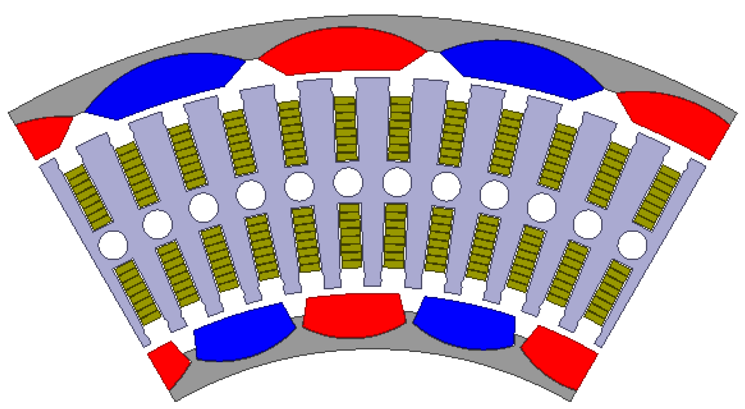
2.1. Machine Structure Design

The structure of the designed DRPMSM in this paper is shown in Figure 1. The inner and outer rotors are rigidly connected by an end cap to ensure the same rotation speed. Screw holes are left in the rotor end cap for connection to the propeller via a flange. The rated rotation speed of the DRPMSM is 2500 rpm. The inner and outer permanent magnets are embedded in the inner and outer rotors, respectively, and the inner and outer rotors share a common stator. In order to increase the torque density of the motor, hairpin windings are used, characterized by high slot fullness and good heat dissipation compared to the conventional round wire winding. The hairpin windings are embedded radially in the stator slots; the ends are connected by welding and the windings are designed as wave windings. Due to the radial embedding of the windings, the stator slot is designed as a rectangular open parallel slot. In order to meet the heat dissipation requirements of high-torque-density motors, cooling holes are provided in the middle yoke of the stator for weight reduction and water cooling, and U-shaped water-cooling tubes are inserted into the apertures of the stator core up to the stator end cap. The U-shaped cooling tubes are made of alumina material to reduce the total weight of the DRPMSM. There are inlet and outlet holes at the stator end cap. The S-shaped partition on the stator end cap separates the cooling water into an S-shaped inflow channel and an S-shaped outflow channel. The inflowing cooling water enters the inflow channel inside the stator end cap, flows into the inflow end of the U-shaped pipe, then flows from the outflow end of the U-shaped pipe into the outflow channel inside the stator end cap, and then out of the outflow holes of the cooling water. The 2D finite element simulation model of the radial flux dual-rotor motor is shown in Figure 2.

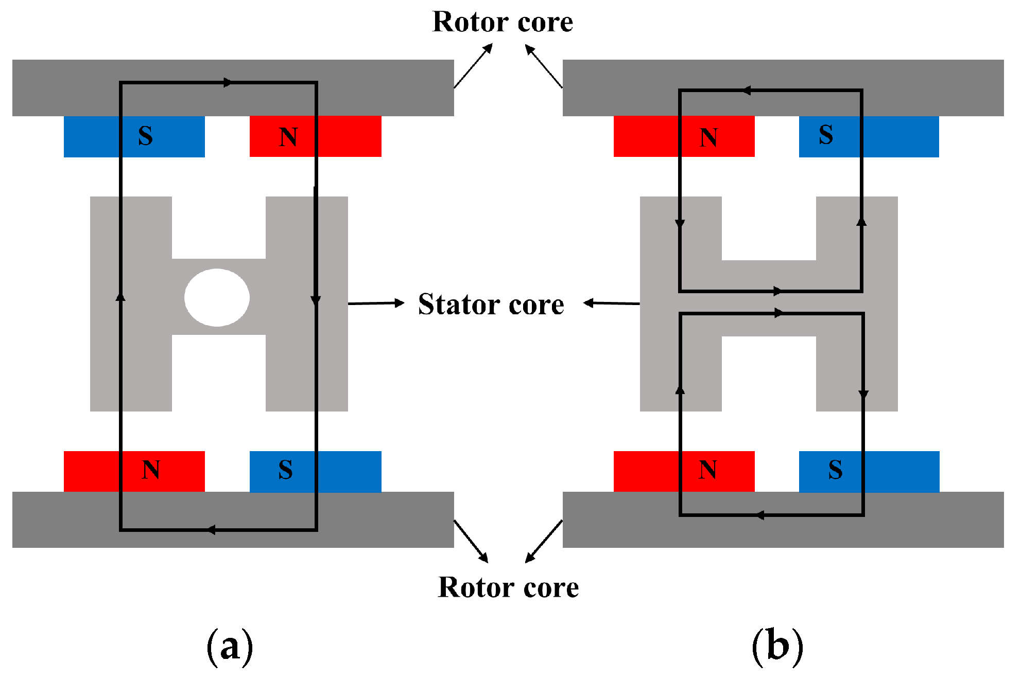
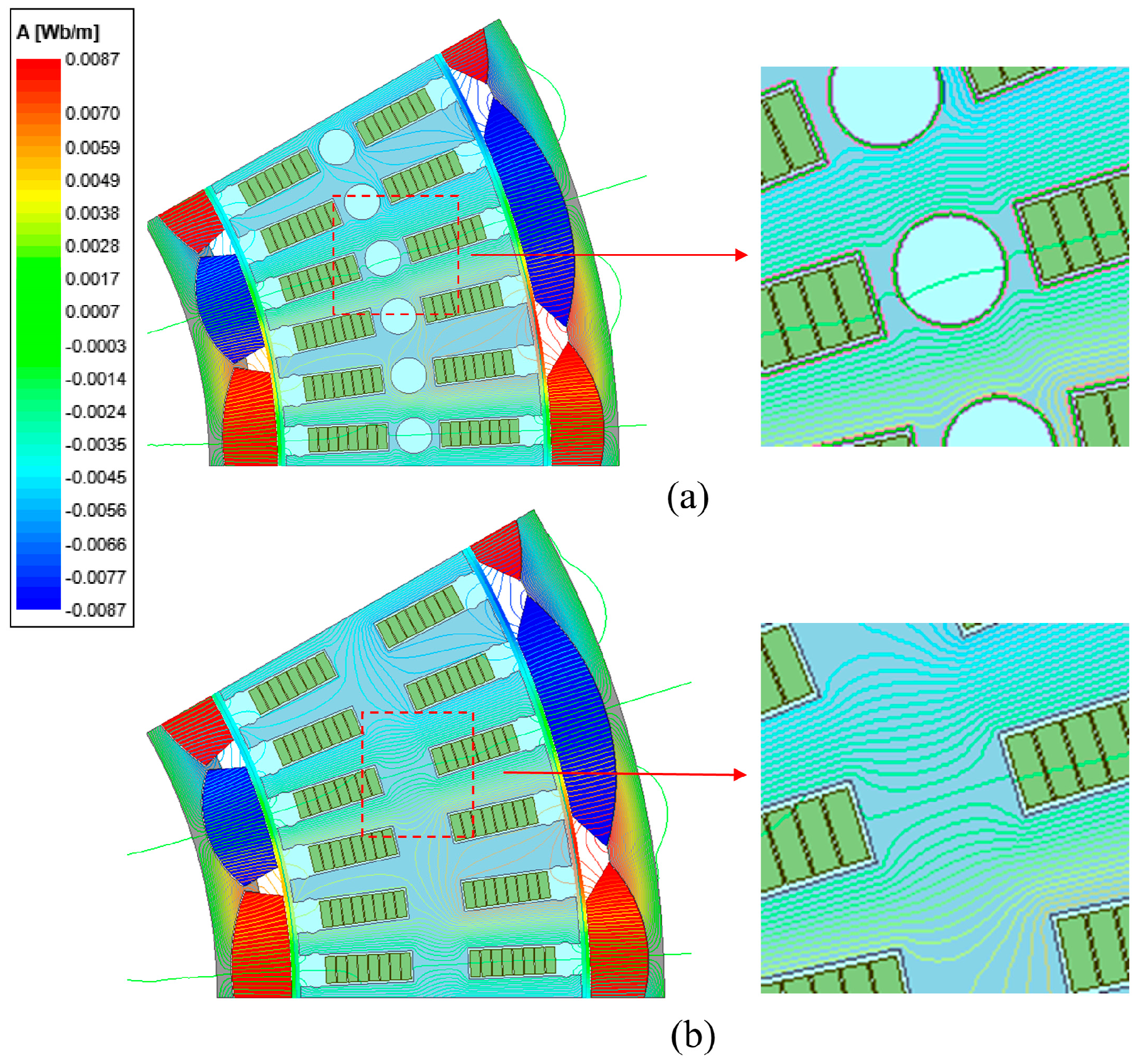
2.2. Magnet Circuit Design

According to the different magnetic pole arrangement of the inner and outer permanent magnets, there are two types of magnetic circuits of the DRPMSM, N-N type and N-S type, as shown in Figure 3. When the N-N type magnetic circuit structure is used, the polarity of the magnetic poles of the inner and outer rotors corresponds to the same, the magnetic fields of the inner and outer rotors are simultaneously cross linked and go along the circumference of the stator yoke, then only a ring winding can be used. When the N-S type magnetic circuit structure—that is, the internal and external rotor poles correspond to the opposite—the magnetic flux driven by magnets will travel radially directly across the stator core; there is no flux traveling along the circumference of the stator core, so the ring winding cannot be used. Only the stack winding or wave winding can be chosen in this case [18]. Since the stator yoke of the N-N type magnetic circuit is required to provide the flux path that follows the circumference, the stator yoke needs to be designed with a certain thickness in order to avoid magnetic saturation. For the N-S type magnetic circuit, the stator teeth provide the radial flux path and the stator yoke does not need to provide the circumference direction flux path; so, the yoke thickness can be designed thinner only to meet the role of the mechanical connection. According to the above characteristics, the DRPMSM designed in this paper is of N-S type magnetic circuit, with circular cooling holes opened in the stator yoke. Table 1 shows the comparison of stator iron loss, average output torque, and torque ripple of the N-S type DRPMSM with and without circular cooling holes in the stator yoke. The stator iron loss increases by 9.7 W, the average torque decreases by 1.6 Nm, and the torque ripple increases by 0.4% when the stator yoke has the cooling hole compared to no hole—that is, the electromagnetic performance of the DRPMSM decreases slightly with cooling holes compared to no holes. This is due to the saturation of the magnetic circuit. The leakage flux of N-S type DRPMSM will follow the circumference along the stator yoke, and the cooling holes at stator yoke will squeeze the leakage flux path so that the stator magnetic circuit is more saturated compared with that having no holes, as shown in Figure 4. The main magnetic circuit of the DRPMSM is not seriously saturated when there are cooling holes, as shown in Figure 5. As a result, the stator iron loss increases and the torque performance also deteriorates. However, the cooling holes in the stator yoke can be a good solution to the weight reduction and heat dissipation problems of the DRPMSM, which is conducive to improving the torque density of the DRPMSM, despite a little torque performance deterioration.

3. Cogging Torque Reduction of DRPMSM

Unlike single-rotor motors, the cogging torque of the DRPMSM consists of the superposition of the inner and outer rotor cogging torque, which tends to be larger than that of a single-rotor motor; if it is not suppressed, it will adversely affect the smooth operation of the direct-drive motor–propeller system. The following is a theoretical analysis of the cogging torque of the DRPMSM.
According to the energy method, the cogging torque is the amount of energy variation with respect to the rotation amount of a rotor and can be represented as follows [26]:
T cog ( θ ) = W g a p θ
where W and θ are the energy in the air gap and the angle of the rotor, respectively.
For the DRPMSM, the total air-gap magnetic field energy is
W c o g = W i n + W o u t = 1 2 μ 0 ( V o u t B o u t 2 d V + V i n B i n 2 d V )
where Bin and Bout are the air-gap flux density distributed along the outer and inner rotor armature surface, respectively.
The distribution of air-gap flux density of the inner and outer motors along the armature surface can be approximately expressed as
B ( θ , α ) = B r ( θ ) h m ( θ ) h m ( θ ) + δ ( θ , α )
where α is the angle between the center line of PM and a specified tooth center line of the outer stator. B(θ,α) are the distribution of the remanence along the circumference of the PMs, g(θ,α) are the distributions of the effective length of the outer and inner air gap along the circumferential direction, and hm(θ) is the distribution of the length along the circumferential direction of the magnetizing direction of the PMs.
The Fourier expansion of Br(θ) on the region [−π/2p, π/2p] is
B r 2 ( θ ) = α p B r 2 + n = 1 B r n cos 2 n p θ
where B r n = 2 n π B r 1 2 s i n   ( n α p π ) , α p is the pole-arc coefficient of the PM, and p is the pole pairs.
Considering the relative position between the PM and the stator teeth, the Fourier expansion of h m ( θ ) h m θ + δ ( θ , α ) 2  in the region [−π/z, π/z] can be expressed as
[ h m ( θ ) h m ( θ ) + δ ( θ , α ) ] 2 = G 0 + n = 1 G n cos n z ( θ + α )
For the DRPMSM proposed in this paper, if the stator and rotor ferromagnetic material is simplified and assumed to be linear, it can be decoupled into inner and outer parts. Each of them produce a cogging torque component, and the sum is the total cogging torque of DRPMSM. Substituting (2)–(5) into (1), the cogging torque expression of DRPMSM can be obtained:
T c o g = T i n + T o u t = π z L a 4 μ 0 ( R 2 2 R 1 2 ) n = 1 n G n 1 B r 1 n z 2 p sin ( n z α ) +   π z L a 4 μ 0 ( R 3 2 R 2 2 ) n = 1 n G n 2 B r 2 n z 2 p sin ( n z α )
where R1 is the inner diameter of the stator, R2 is the middle diameter of the stator, and R3 is the outer diameter of the stator.
From (6), it can be seen that when the basic size of the motor is determined, it is the Fourier coefficients Gn and Bn that determine the amplitude of the cogging torque; then, there are two ways to weaken the cogging torque of the dual-rotor based on the rotor side: the first one is to weaken the amplitude of the inside and outside cogging torque Tin, Tout, respectively, and the second one is that according to the sinusoidal nature of the cogging torque it is possible to carry out the phase inversion of the fundamental wave of the inside and outside cogging torque, so the inside and outside cogging torque are superimposed inversely, which will lead to weakening of the total cogging torque.

3.1. Permanent Magnet Shape Design

In order to weaken the amplitude of the single side cogging torque of DRPMSM, a permanent magnet with an inner pole-arc eccentric plus chamfering angle structure is designed in this paper, as shown in Figure 6.
O is the center of the motor and also the center of the circle corresponding to the outer pole arc of the inner permanent magnet; O′, O″ are the centers of the circles corresponding to the inner pole arc of the inner and outer permanent magnets; h1, h2 are the thicknesses of the permanent magnets of the inner and outer permanent magnets when the inner pole arcs of the inner and outer permanent magnets are not eccentric; γ1, β1 are the chamfer angle of the inner and outer permanent magnets; γ, β are the angles of the tensor angles of the inner and outer permanent magnets corresponding to the Tensor angle of the motor center of the inner and outer permanent magnets. This design can change the pole-arc coefficient of the permanent magnet by changing γ and β, change d1 and d2 to control the eccentric thickness of the permanent magnet, and change γ1 and β1 to control the chamfering angle of the inner and outer permanent magnets.
For the shape of permanent magnets designed in this paper, which are of unequal thicknesses, both the thickness of the permanent magnets and the air-gap length vary with the rotor position angle, which are denoted as hm(θ) and g(θ,α), respectively, and the radial air-gap flux density is
B ( θ ) = B r ( θ ) h m ( θ ) h m ( θ ) + g ( θ , α ) = h m ( θ ) h m B r ( θ ) h m h m ( θ ) + g ( θ , α )
where hm is the thickness of the permanent magnet when designed without eccentric chipping. Denote Br (θ) as the equivalent remanence magnetization density distribution, and let
B r ( θ ) = B r ( θ ) h m ( θ ) h m
so,
B ( θ ) = B r ( θ ) h m h m ( θ ) + g ( θ , α ) = B r ( θ ) G ( θ )
The Fourier coefficient Gn of G′(θ) varies very little with hm(θ) and can be considered approximately constant, while the Fourier coefficient Brn of Br′(θ) varies more with hm(θ). The Fourier decomposition of B r 2 θ yields the Fourier coefficient B r n z 2 p , which determines the amplitude of the cogging torque. The pole–slot combination of the DRPMSM designed in this paper is 72s24p; then, the cogging torque is only related to the 6kth Fourier coefficient of B r 2 θ , so its amplitude is mainly determined by Br6. Take the outer rotor as an example and take the pole-arc coefficients as 0.93, 0.86, and 0.76; the relationship between the eccentric distance d2, chamfer angle β1, and Br6 is shown in Figure 7. The fundamental Fourier coefficient Br6 rises at first and then decreases with the increase in eccentric distance. In the design of the permanent magnet shape in this paper, the increase in the eccentric distance leads to the increase in the thickness of the permanent magnet, which may be the reason for the rise of Br6 at first; meanwhile, Br6 begins to decrease when the eccentric distance is greater than 1.5 mm and its Br6 is a little bit smaller than the initial value when the eccentric distance is 3 mm. This shows that Br6 can be reduced by the design of the eccentric distance to weaken the amplitude of the cogging torque. The Br6 of the cogging torque shows a decreasing trend with the increase in the chamfer angle, which is due to the fact that the chamfer angle of the edge of the permanent magnet improves the distribution of B(θ) in the transition region. The chamfer angle changes B(θ) from a sudden decrease to zero to a gradual decrease to zero, which has a weakening effect on Br6. However, the chamfer angle cannot be designed too large, because too large a chamfer angle will reduce the thickness of the permanent magnet, resulting in a weakening of the output electromagnetic torque.
Figure 8 shows the effect of eccentric distance and chamfer angle of the outer rotor’s permanent magnets on the amplitude of cogging torque. At the same eccentric distance, the magnitude of the cogging torque decreases with the increase in the chamfer angle; at the same chamfer angle, the magnitude of the cogging torque increases at first and then decreases with the increase in the eccentric distance. When the permanent magnet is not designed with an eccentric and chamfered shape, the peak value of cogging torque is 23.41 Nm. When the chamfer angle is 2.4 deg and the eccentric distance is 1.2 mm, the peak value of cogging torque of the external rotor achieves a minimum value of 1.97 Nm, which is weakened by 91.5%. Therefore, the permanent magnet shape design in this paper can significantly weaken the cogging torque amplitude.
The effect of eccentric distance and chamfer angle on the torque performance of the outer rotor motor is shown in Figure 9. For the average output torque of the outer rotor, the increase in the chamfer angle decreases the average value of output torque at the same eccentric distance. At the same chamfer angle, the average output torque increases and then decreases with the increase in eccentric distance, and all of them obtain a maximum value near 1.6 mm. This indicates that the air-gap magnetization fundamental waveform amplitude is maximized when the eccentric distance is about 1.6 mm, and the chamfer angle reduces the fundamental waveform of the air-gap magnetization. When the chamfer angle is 0 deg and the eccentric distance is 1.6 mm, the average output torque reaches a maximum of 69.6 Nm. At the minimum value of the cogging torque, the output torque is 67.3 Nm. For the torque ripple, at the same eccentric distance, the torque ripple has a significant decrease with the increase in the chamfer angle, and the torque ripple decreases to the minimum with the increase in the chamfer angle at about 2 deg. As the chamfer angle increases from 2 deg to 2.4 deg, the torque ripple increases again. When the chamfer angle is constant, the torque ripple does not change significantly with the increase in eccentric distance. When the chamfer angle is 2 deg and the eccentric distance is 1.8 mm, the torque ripple achieves the minimum value of 5.68%.

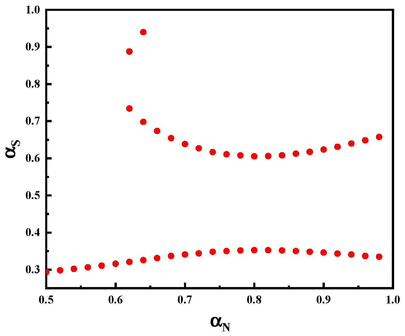
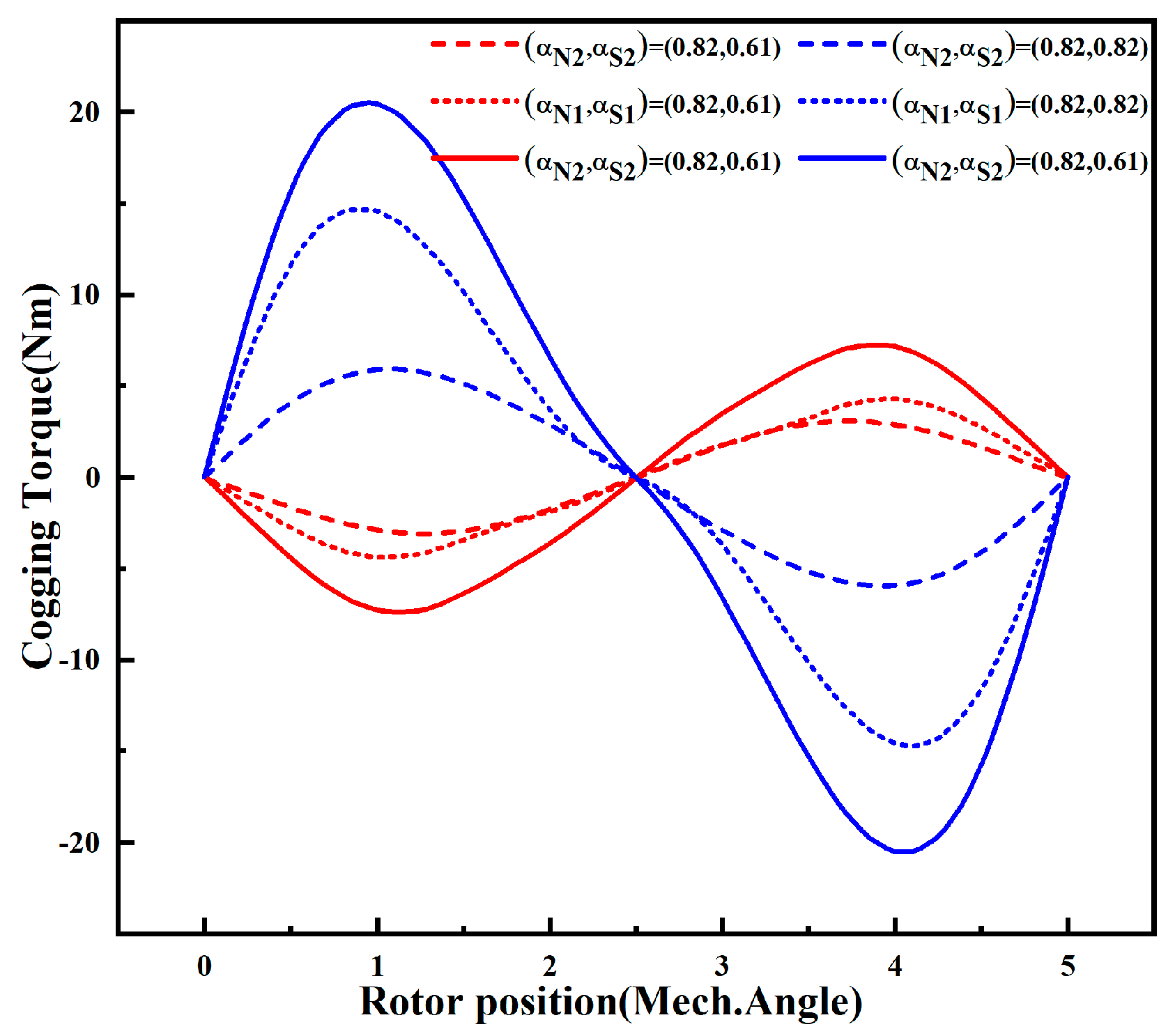
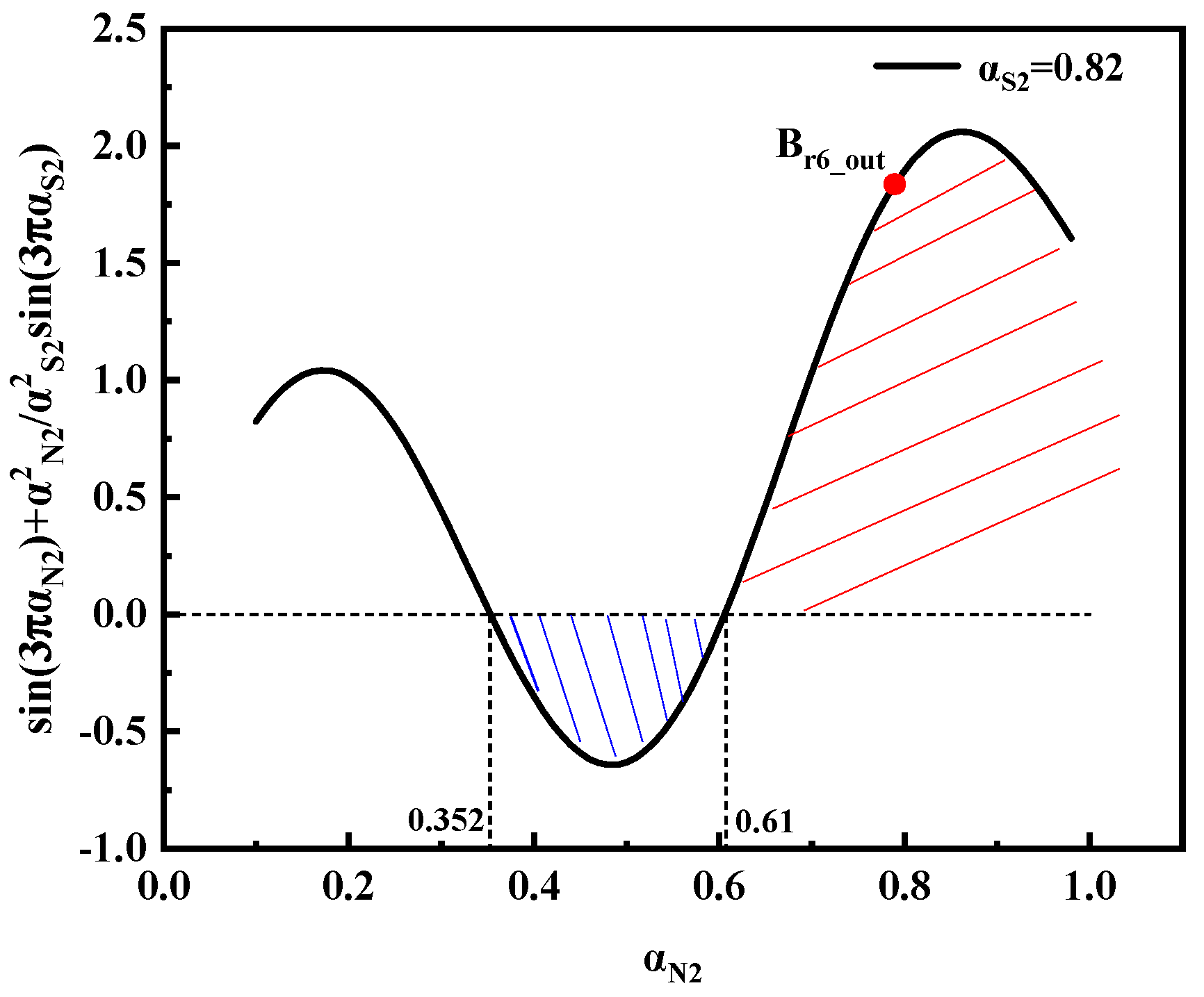
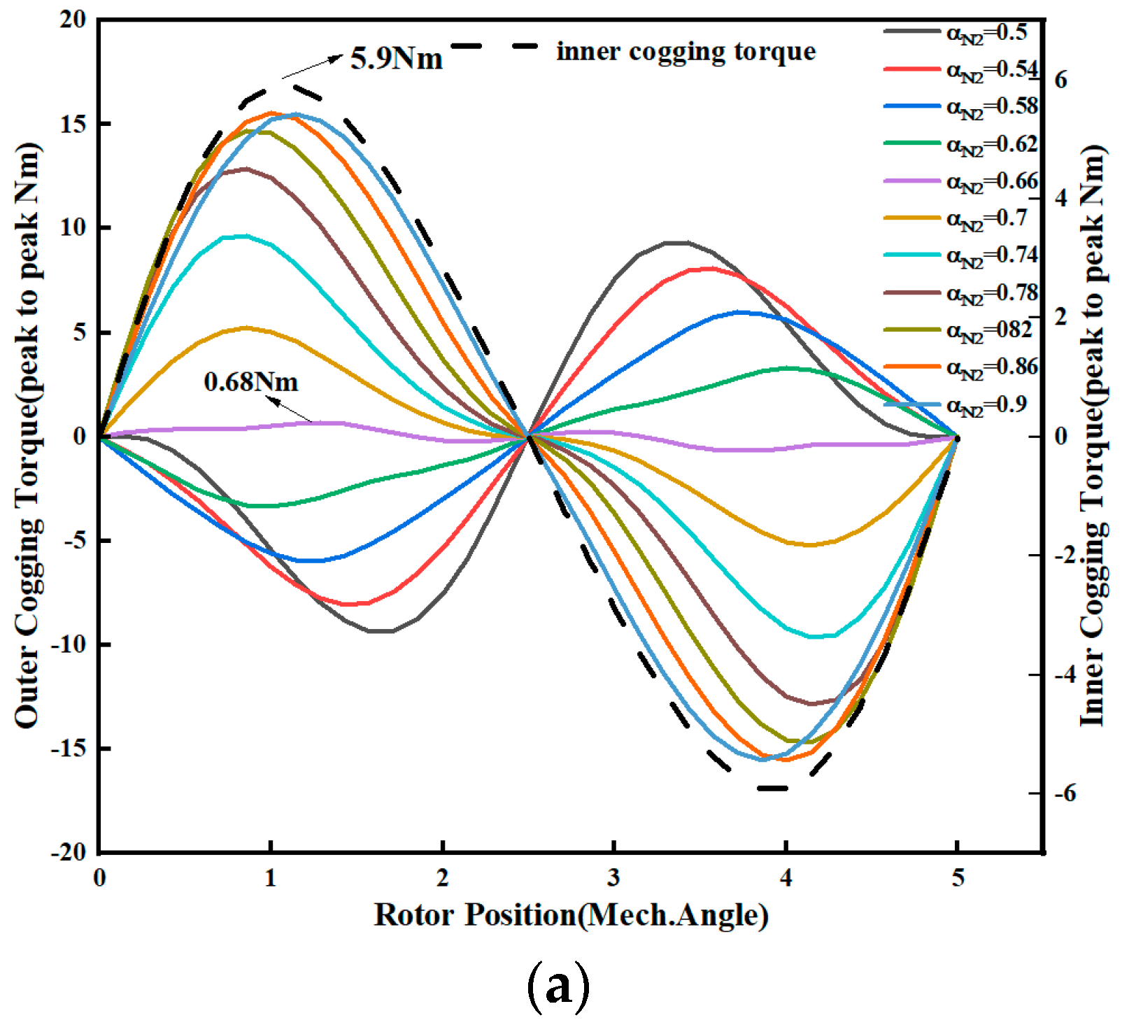
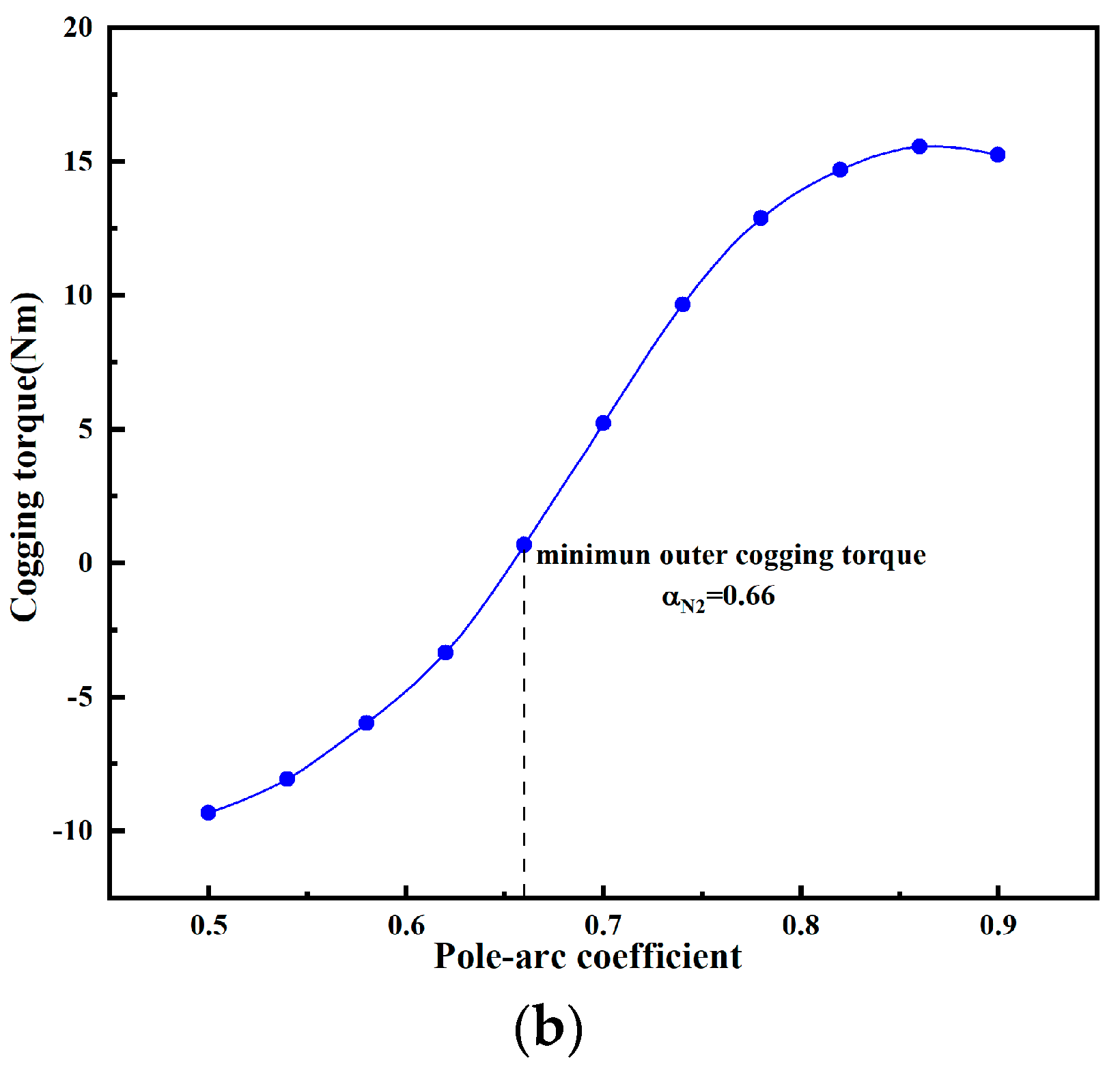
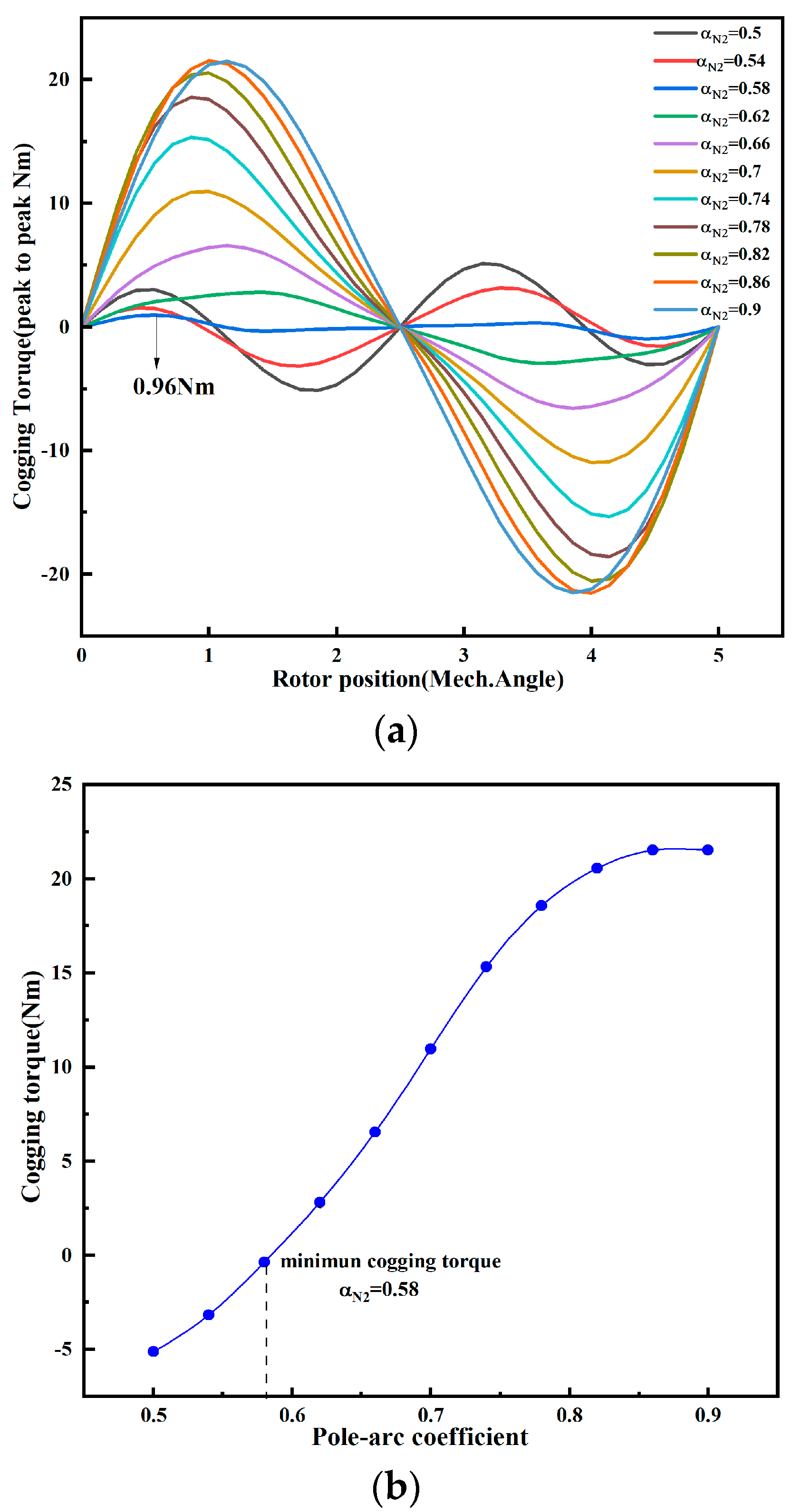
3.2. Pole-Arc Combination Design

For the permanent magnet shape with eccentricity plus chamfer angle proposed above, the unilateral cogging torque can be effectively weakened by weakening the fundamental wave Brn of the unilateral rotor. However, the cogging torque of the DRPMSM is superimposed by the cogging torques of the inner and outer rotors. According to this feature, in addition to weakening the amplitude of the cogging torque of the single-side cogging torque by the shape of the permanent magnets as proposed above, it can also be made possible to make the phase of the inner and outer cogging torques differ by 180 degrees from each other—i.e., the fundamental waves of the inner and outer rotors Brn1 and Brn2 are different in sign—so that the inner and outer cogging torques will cancel each other and the total cogging torque amplitude of the dual-rotor motor can be weakened.
In this paper, a combination of pole-arc coefficients is proposed—that is, the two pole-arc coefficients within a pair of poles are unequal and the two magnetic poles separated by two pole distances have the same structural dimensions, as shown in Figure 10. When a combination of pole-arc coefficients is used, Brn in the expression of the cogging torque changes to
B r n z p _ o u t = B r 1 2 n π [ sin ( α N 1 2 n π ) + ( 1 ) n α N 1 2 α S 1 2 sin ( α S 1 2 n π ) ] B r n z p _ i n = B r 2 2 n π [ sin ( α N 2 2 n π ) + ( 1 ) n α N 2 2 α S 2 2 sin ( α S 2 2 n π ) ]
For the weakening of the inner and outer cogging torque fundamental waves, let
B r n z p _ o u t B r n z p _ i n 0
make the internal and external cogging torque fundamental wave invert, thus weakening the total cogging torque. The DRPMSM designed in this paper has a pole–slot combination of 72s24p, and only the 6nth Fourier coefficients of Brn have effect on the cogging torque. At this time, the Fourier coefficients that determine the amplitude of the inner and outer cogging torque’s fundamental wave are Br6. The combination of pole-arc coefficients is used to weaken the total cogging torque amplitude of the DRPMSM in the following two methods:
(1)
Method one:
This approach weakens the cogging torque by combining the polar arc coefficients so that the amplitude of the inner and outer cogging torque’s fundamental wave are zero:
B r 2 6 π [ sin ( 3 π α N 1 ) + ( 1 ) n α N 1 2 α S 1 2 sin ( 3 π α S 1 ) ] = 0 B 2 r 6 π [ sin ( 3 π α N 2 ) + ( 1 ) n α N 2 2 α S 2 2 sin ( 3 π α S 2 ) ] = 0
This combination of calculated pole-arc coefficients according to (12) is shown in Figure 11.
The cogging torque of the outer rotor with pole-arc coefficients combination and without combination is shown in Figure 12. When (αN1, αS1) = (0.82, 0.82), the amplitude of the cogging torque is 14.8 Nm; when (αN1, αS1) = (0.82, 0.61), the base wave of the cogging torque is theoretically 0, and the amplitude of the cogging torque is 4.9 Nm, which is 66.9% lower compared to the equal pole-arc coefficient. The total cogging torque is reduced from 21.8 Nm to 8.9 Nm, which is 59.17% lower compared to the equal polar arc coefficient when both the inner and outer rotors are combined with pole-arc coefficients (0.82, 0.61). In this way, although the base wave of the cogging torque is theoretically 0, the inner and outer cogging torque are still superimposed in the same direction and the total cogging torque is still large.
(2)
Method two:
This method makes the inner and outer cogging torque fundamental waves cancel each other by combining the polar arc coefficients to weaken the total cogging torque:
B r 2 6 π [ sin ( 3 π α N 1 ) + ( 1 ) n α N 1 2 α S 1 2 sin ( 3 π α S 1 ) ] · B r 2 6 π [ sin ( 3 π α N 2 ) + ( 1 ) n α N 2 2 α S 2 2 sin ( 3 π α S 2 ) ] < 0
Take αN1 = αS1 = αS2 = 0.82 as an example. The fundamental wave Br6_out of the outer rotor is located in the red dot position in Figure 13, and Br6_out > 0. If we want to make the inner and outer cogging torque inverted, αN2 should be selected in the interval (0.352, 0.607); at this time, the inner rotor’s Br6_in < 0, the phase difference of the fundamental wave of the inner and outer cogging torque is about 180°, the inner and outer cogging torque can realize the inverse superposition, and the total cogging torque of the DRPMSM can be weakened.
The finite element validation is shown in Figure 14. As αN2 varies, the inner rotor cogging torque remains constant and is positive in the first half-cycle. The peak value is 5.9 Nm. When αN2 is in the interval (0.5, 0.62), the outer rotor cogging torque is negative in the first half-cycle, which counteracts the inner rotor cogging torque, and the peak value decreases with the increase in αN2. When αN2 = 0.62, the amplitude of the outer cogging torque reaches a minimum value of 0.68 Nm. When αN2 is in the interval (0.62, 0.9), the outer cogging torque is positive in the first half of the cycle, superimposed in the same direction with the inner rotor cogging torque, and the peak value gradually increases with the increase in αN2. For the total cogging torque of the DRPMSM, its minimum value is obtained at αN2 = 0.58, which is 0.96 Nm, when the inner and outer cogging torques are superimposed inversely, as shown in Figure 15.
Taking the polar arc coefficients in the interval (0.5, 0.96), the cogging torque, average torque, and torque ripple of the outer rotor when the combination of polar arc coefficients is used are shown in Figure 16. When the pole-arc coefficient combination is (0.862, 0.655), the cogging torque achieves a minimum value of 1.4 Nm. When smaller pole-arc coefficients are used, it will make the amplitude of the fundamental wave of air-gap flux density smaller, which is unfavorable to the average output torque. When the combination of pole-arc coefficient is (0.96, 0.96), the average output torque of the outer rotor reaches a maximum value of 70.89 kW. The torque ripple at this time is 44.9%. When the combination of pole-arc coefficient is (0.856, 0.6160), the minimum torque ripple is 9.6%.

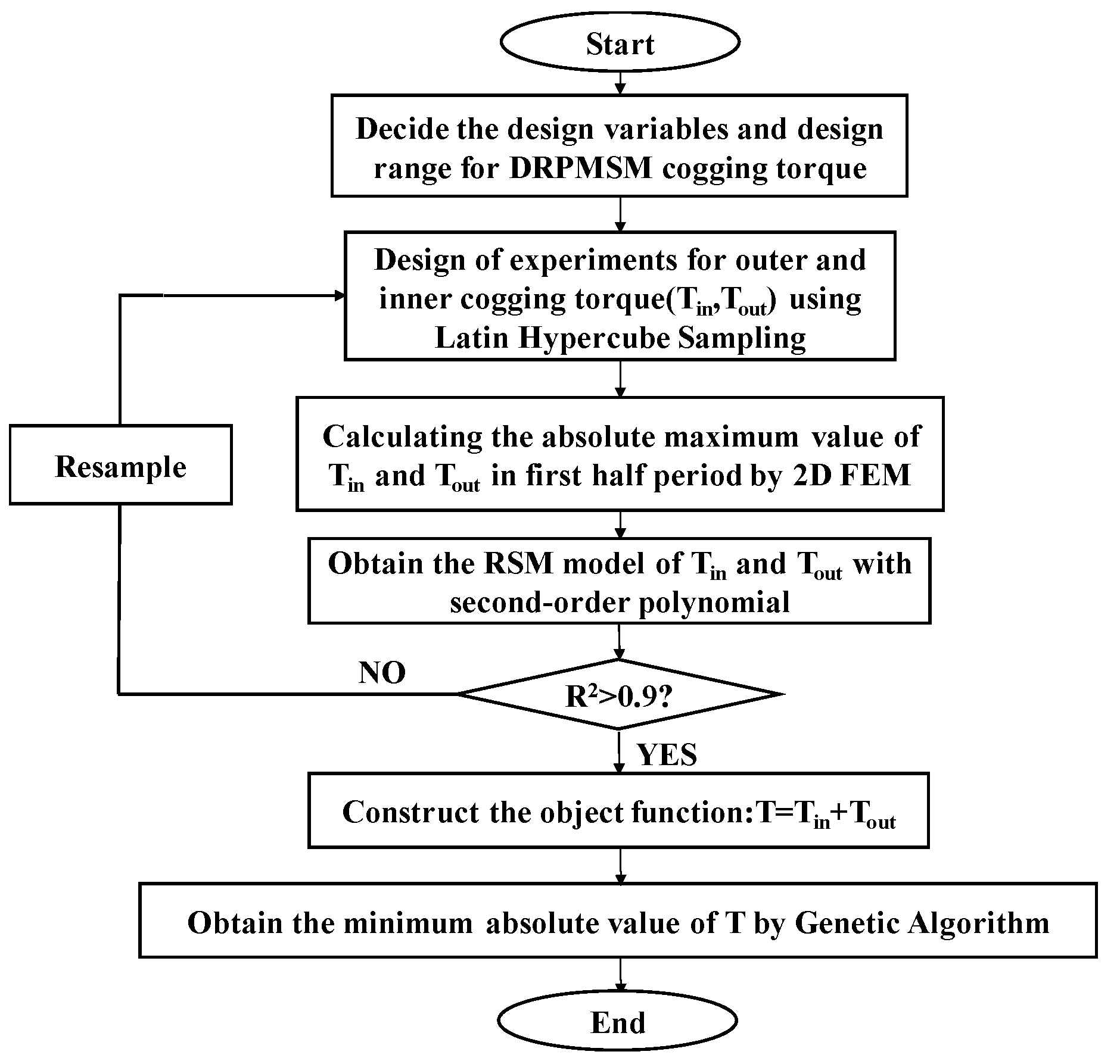
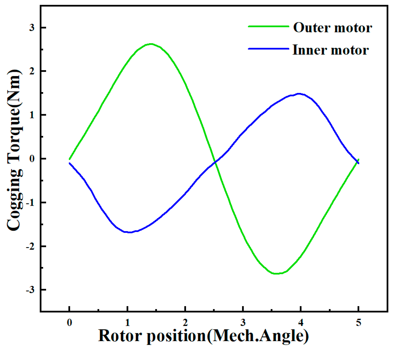
3.3. Cogging Torque Optimization

Since the weakening of the cogging torque of the DRPMSM by one method alone is limited, this paper combines the above two methods to weaken the cogging torque of DRPMSM by multi-parameter composite permanent magnet structure optimization. The response surface method is used to establish a mathematical model between the polar arc coefficient, chamfer angle, eccentric distance, and cogging torque of the DRPMSM.
In this paper, polynomial regression is used for response surface modeling. A direct polynomial regression of the cogging torque amplitude of the DRPMSM on eight variables would make the problem highly dimensional, computationally intensive, and difficult to design an experiment for. Considering the superposition characteristics of the cogging torque of the DRPMSM and the phase superposition problem of the cogging torque of the inner and outer cogging torque, this paper chooses the 4-element second-order response surface function expressed as
Y = β 0 + i = 1 4 β i x i + i = 1 4 β i i x i 2 + i j 4 β i j x i x j + ε
where Y is the response, β is the regression coefficient to be estimated, ε is the fitting error, and x is the dependent variable.
The experimental design uses Latin square sampling to sample the parameter combination, and the number of both inner rotor and outer rotor samples is 60. The value of cogging torque under the above parameter combination is obtained by finite element analysis. Then, we regress the maximum value of the inner and outer cogging torque in the first half cycle, respectively, and the two are added to obtain the maximum value of the total cogging torque of the DRPMSM in the first half-cycle.
To ensure the accuracy of the response surface model, the correlation coefficient R2 of the regression equation is required to be larger than 0.9. The regression equations for the maximum value of internal and external cogging torque are obtained, respectively:
T i n = 73.05 + 15.72 α 1 + 9.89 d 1 100.38 α N 1 + 217.38 α S 1 + 2.54 α 1 2 + 1.76 d 1 2 + 87.66 α N 1 2 102.78 α S 1 2 1.83 α 1 d 1 6.44 α 1 α N 1 22.3 α 1 α S 1 8.26 d 1 α S 1 8.81 d 1 α S 1 10.07 α N 1 α S 1
T o u t = 56.25 + 20.23 α 1 + 7.68 d 1 87.88 α N 1 + 154.48 α S 1 + 5.89 α 1 2 + 1.25 d 1 2 + 100.68 α N 1 2 73.35 α S 1 2 0.98 α 1 d 1 3.69 α 1 α N 1 27.43 α 1 α S 1 7.33 d 1 α S 1 9.08 d 1 α S 1 6.57 α N 1 α S 1
T c o g = T i n + T o u t
After obtaining the response surface model of the total cogging torque Tcog, the total cogging torque is optimized using a genetic algorithm. The optimization formulation of cogging torque can be defined as follows:
M i n i m i z e : a b s ( T c o g ) C o n s t r a ints : 0 α 1 , β 1 2.4 , 0 d 1 , d 2 3       0.58 α N 1 , α N 2 , α S 1 , α S 2 0.9
The optimization flowchart is shown in Figure 17.
The combination of permanent magnets parameters with minimum cogging torque are shown in Table 2, and the comparison of torque performance before and after optimization is shown in Table 3. The optimized cogging torque amplitude is reduced from 32.85 Nm to 1.21 Nm, as shown in Figure 18. This shows that the cogging torque of the DRPMSM is greatly weakened by the combination of two methods: the eccentric and chamfered permanent magnet shape design and the combination of inner and outer rotor pole-arc coefficients. The output torque amplitude decreases slightly from 119.48 Nm to 110.21 Nm. By weakening the cogging torque, the torque ripple is also reduced from 32.1% to 2.9%.

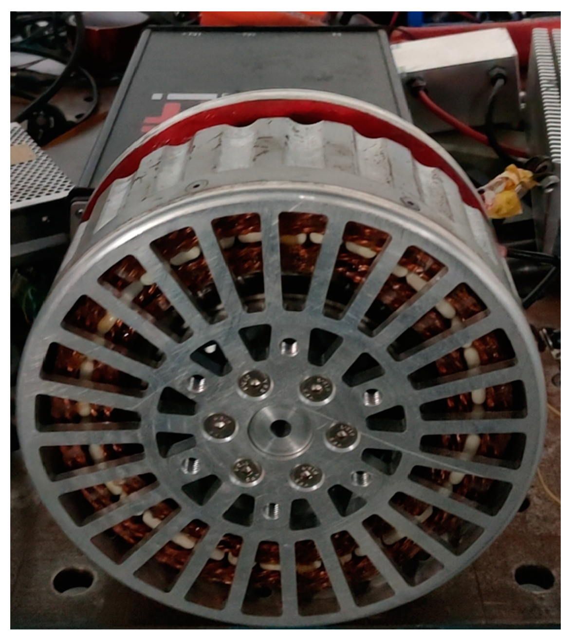
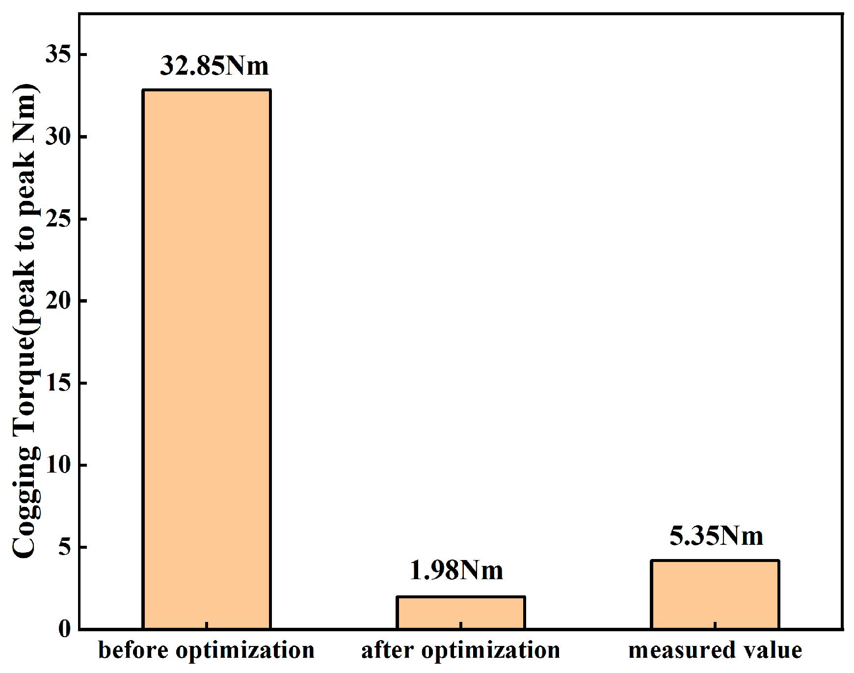
4. Experimental Validation

In order to verify the rationality of the DRPMSM designed in this paper as well as the reasonableness of the theoretical analysis, an experimental prototype was fabricated based on the results of the optimized design, as shown in Figure 19. The values of cogging torque obtained from the prototype and simulation were measured experimentally to be 5.35 Nm and 1.98 Nm, respectively, as shown in Figure 20. The test results of the cogging torque are greater than the finite element simulation results. This is due to the fact that the ideal finite element model cannot take into account the machining error of the prototype and the mechanical friction of the test platform, resulting in a larger measured value of the cogging torque compared to the simulation results.

5. Conclusions

In this paper, a high-torque-density dual-rotor radial flux permanent magnet synchronous motor (DRPMSM) for electrical aircraft is first designed; then, its structural characteristics and magnetic circuit are analyzed. An eccentric and chamfered permanent magnet shape design is given to weaken the cogging torque of the DRPMSM. The relationship between the influence of eccentric distance and chamfer angle on the amplitude of cogging torque is obtained. The results show that the eccentric and chamfered permanent magnet shape can significantly weaken the cogging torque amplitude but also make the output torque decrease.
For the superposition characteristics of the cogging torque in the DRPMSM, the pole-arc coefficients combination method is proposed. By combining the pole-arc coefficients of the single-side rotor, weakening of the amplitude of the cogging torque of the single side can be realized, the combination of which is shown in (12). By combining the pole-arc coefficients of both the inner and outer rotors, the inner and outer cogging torques can be canceled out with each other, the combination of which is shown in (13); thus, further weakening of the overall cogging torque is realized. The mathematical models of inner and outer rotor pole-arc coefficients, eccentric distance, and chamfer angle with the cogging torque of the DRPMSM are established by the response surface method. The cogging torque of the DRPMSM is optimized using genetic algorithms, and the combination of permanent magnet structural parameters that minimizes the cogging torque is obtained. After optimization, the cogging torque is 1.98 Nm, which is 93.97% lower than the initial model, and the torque ripple is significantly suppressed, but there is a small decrease in the output torque.
The prototype was manufactured and tested for cogging torque of the DRPMSM, and the test result was 5.35 Nm, which verifies the correctness of the above theoretical analysis and the effectiveness of the optimization.

Author Contributions

Methodology, Y.G. and J.W.; Validation, L.L.; Writing—original draft, H.L. and M.F. All authors have read and agreed to the published version of the manuscript.

Funding

This research received no external funding.

Data Availability Statement

The original contributions presented in the study are included in the article, further inquiries can be directed to the corresponding author.

Conflicts of Interest

The authors declare no conflict of interest.

References

  1. Tabuchi, H. Worse than Anyone Expected’: Air Travel Emissionsvastly Outpace Predictions. The New York Times, 19 September 2019. [Google Scholar]
  2. Wheeler, P.W.; Sirimanna, T.S.; Bozhko, S.V.; Haran, K.S. Electric/Hybrid-Electric Aircraft Propulsion Systems. Proc. IEEE 2021, 109, 1115–1127. [Google Scholar] [CrossRef]
  3. Agrawal, S.; Banerjee, A.; Beach, R.F. Brushless Doubly-Fed Reluctance Machine Drive for Turbo-Electric Distributed Propulsion Systems. In Proceedings of the 2018 AIAA/IEEE Electric Aircraft Technologies Symposium (EATS), Cincinnati, OH, USA, 12 July 2018; pp. 1–17. [Google Scholar]
  4. Brown, G.V. Weights and Efficiencies of Electric Components of a Turboelectric Aircraft Propulsion System. In Proceedings of the Weights and Efficiencies of Electric Components of a Turboelectric Aircraft Propulsion System, Orlando, FL, USA, 4–7 January 2011. [Google Scholar]
  5. Kowalczyk, M.; Vezzini, A.; Grzesiak, L.M. Cylindrical double air gap motor for aerial applications. Przegląd Elektrotechniczny 2013, 2000, 150. [Google Scholar]
  6. Cao, W.; Mecrow, B.C.; Atkinson, G.J.; Bennett, J.W.; Atkinson, D.J. Overview of Electric Motor Technologies Used for More Electric Aircraft (MEA). IEEE Trans. Ind. Electron. 2012, 59, 3523–3531. [Google Scholar]
  7. Ganev, E. Selecting the Best Electric Machines for Electrical Power-Generation Systems: High-performance solutions for aerospace More electric architectures. IEEE Electrif. Mag. 2014, 2, 13–22. [Google Scholar] [CrossRef]
  8. Sayed, E.; Abdalmagid, M.; Pietrini, G.; Sa’adeh, N.-M.; Callegaro, A.D.; Goldstein, C.; Emadi, A. Review of Electric Machines in More-/Hybrid-/Turbo-Electric Aircraft. IEEE Trans. Transp. Electrif. 2021, 7, 2976–3005. [Google Scholar] [CrossRef]
  9. Chandel, D.; Reband, J.D.; Hall, D.K.; Balachandran, T.; Xiao, J.; Haran, K.S.; Greitzer, E.M. Fan and Motor Co-Optimization for a Distributed Electric Aircraft Propulsion System. IEEE Trans. Transp. Electrif. 2023, 9, 3579–3589. [Google Scholar] [CrossRef]
  10. Fan, Y.; Liang, P.; Liang, L.; Zhang, D.; Liu, W.; Zhang, X. Analytical model of no-load axial force for electric propulsion conical motor in electric aircraft. IET Electr. Power Appl. 2023, 18, 336–344. [Google Scholar] [CrossRef]
  11. Hebala, A.; Nuzzo, S.; Volpe, G.; Connor, P.H.; Giangrande, P.; Gerada, C.; Galea, M. Feasibility Design Study of High-Performance, High-Power-Density Propulsion Motor for Middle-Range Electric Aircraft. In Proceedings of the 2020 IEEE 29th International Symposium on Industrial Electronics (ISIE), Delft, The Netherlands, 17–19 June 2020; pp. 300–306. [Google Scholar]
  12. Jike, N.; Mitsuda, H.; Kojima, T.; Hazeyama, M. Design and Fabrication of Dual-Rotor Motors with Axially Extended Stator for Electrified Aircraft Propulsion. In Proceedings of the 2022 25th International Conference on Electrical Machines and Systems (ICEMS), Chiang Mai, Thailand, 29 November–2 December 2022; pp. 1–5. [Google Scholar]
  13. Talebi, D.; Gardner, M.C.; Sankarraman, S.V.; Daniar, A.; Toliyat, H.A. Electromagnetic Design Characterization of a Dual Rotor Axial Flux Motor for Electric Aircraft. IEEE Trans. Ind. Appl. 2021, 58, 7088–7098. [Google Scholar] [CrossRef]
  14. Wiley, C.; Talebi, D.; Sankarraman, S.V.; Gardner, M.C.; Benedict, M. Design of a Carbon Fiber Rotor in a Dual Rotor Axial Flux Motor for Electric Aircraft. In Proceedings of the 2022 IEEE Energy Conversion Congress and Exposition (ECCE), Detroit, MI, USA, 9–13 October 2022; pp. 1–8. [Google Scholar]
  15. Deodhar, R.P.; Staton, D.A.; Jahns, T.M.; Miller, T.J.E. Prediction of cogging torque using the flux-MMF diagram technique. In Proceedings of the IAS ‘95. Conference Record of the 1995 IEEE Industry Applications Conference Thirtieth IAS Annual Meeting, Orlando, FL, USA, 8–12 October 1995; Volume 691, pp. 693–700. [Google Scholar]
  16. Le-Huy, H.; Perret, R.; Feuillet, R. Minimization of Torque Ripple in Brushless DC Motor Drives. IEEE Trans. Ind. Appl. 1986, IA-22, 748–755. [Google Scholar]
  17. Wanjiku, J.; Khan, M.A.; Barendse, P.S.; Pillay, P. Influence of Slot Openings and Tooth Profile on Cogging Torque in Axial-Flux PM Machines. IEEE Trans. Ind. Electron. 2015, 62, 7578–7589. [Google Scholar] [CrossRef]
  18. Carraro, E.; Bianchi, N.; Zhang, S.; Koch, M. Design and Performance Comparison of Fractional Slot Concentrated Winding Spoke Type Synchronous Motors with Different Slot-Pole Combinations. IEEE Trans. Ind. Appl. 2018, 54, 2276–2284. [Google Scholar] [CrossRef]
  19. Xia, C.; Chen, Z.; Shi, T.; Wang, H. Cogging Torque Modeling and Analyzing for Surface-Mounted Permanent Magnet Machines with Auxiliary Slots. IEEE Trans. Magn. 2013, 49, 5112–5123. [Google Scholar] [CrossRef]
  20. Xintong, J.; Jingwei, X.; Yong, L.; Yongping, L. Theoretical and Simulation Analysis of Influences of Stator Tooth Width on Cogging Torque of BLDC Motors. IEEE Trans. Magn. 2009, 45, 4601–4604. [Google Scholar] [CrossRef]
  21. Dosiek, L.; Pillay, P. Cogging Torque Reduction in Permanent Magnet Machines. IEEE Trans. Ind. Appl. 2006, 43, 1565–1571. [Google Scholar] [CrossRef]
  22. Hwang, S.-M.; Eom, J.-B.; Jung, Y.; Lee, D.-W.; Kang, B.-S. Various design techniques to reduce cogging torque by controlling energy variation in permanent magnet motors. IEEE Trans. Magn. 2001, 37, 2806–2809. [Google Scholar] [CrossRef]
  23. Ashabani, M.; Mohamed, Y.A.-R.I. Multiobjective Shape Optimization of Segmented Pole Permanent-Magnet Synchronous Machines with Improved Torque Characteristics. IEEE Trans. Magn. 2011, 47, 795–804. [Google Scholar] [CrossRef]
  24. Hwang, M.-h.; Lee, H.-S.; Yang, S.-H.; Lee, G.-S.; Han, J.-H.; Kim, D.-H.; Kim, H.-W.; Cha, H.R. Cogging Torque Reduction and Offset of Dual-Rotor Interior Permanent Magnet Motor in Electric Vehicle Traction Platforms. Energies 2019, 12, 1761. [Google Scholar] [CrossRef]
  25. Qu, R.; Lipo, T.A. Dual-rotor, radial-flux, toroidally-wound, permanent-magnet machines. In Proceedings of the Conference Record of the 2002 IEEE Industry Applications Conference. 37th IAS Annual Meeting (Cat. No.02CH37344), Pittsburgh, PA, USA, 15 October 2002; Volume 1282, pp. 1281–1288. [Google Scholar]
  26. Zhu, L.; Jiang, S.Z.; Zhu, Z.Q.; Chan, C. Analytical Methods for Minimizing Cogging Torque in Permanent-Magnet Machines. IEEE Trans. Magn. 2009, 45, 2023–2031. [Google Scholar] [CrossRef]
Figure 1. Structure of the DRPMSM.
Energies 17 01583 g001
Figure 2. 2D finite element model of the DRPMSM.
Energies 17 01583 g002
Figure 3. Two types of magnetic circuit of the DRPMSM: (a) N-S type; (b) N-N type.
Energies 17 01583 g003
Figure 4. Flux line distribution of the N-S type DRPMSM (a) with cooling holes and (b) without cooling holes.
Energies 17 01583 g004
Figure 5. Flux density distribution of rated load condition.
Energies 17 01583 g005
Figure 6. Permanent magnet shape: (a) inner permanent magnet shape; (b) outer permanent magnet shape.
Energies 17 01583 g006
Figure 7. The influence of eccentric distance and chamfer angle on the fundamental Fourier coefficient Br6 of the outer cogging torque: (a) eccentric distance; (b) chamfer angle.
Energies 17 01583 g007
Figure 8. The influence of eccentric distance and chamfer angle on the amplitude of the outer cogging torque: (a) eccentric distance; (b) chamfer angle.
Energies 17 01583 g008
Figure 9. The influence of eccentricity and chamfer angle on the outer rotor’s torque performance: (a) cogging torque; (b) output torque; (c) torque ripple.
Energies 17 01583 g009
Figure 10. Pole-arc combination of inner and outer permanent magnets.
Energies 17 01583 g010
Figure 11. Pole-arc combinations that make Br6 equal to zero.
Energies 17 01583 g011
Figure 12. Comparison of cogging torque before and after pole-arc combination.
Energies 17 01583 g012
Figure 13. The variation of Br6_out with αN2.
Energies 17 01583 g013
Figure 14. The variation of the outer cogging torque with αN2: (a) outer cogging torque waveforms; (b) peak value of the outer cogging torque at first half-cycle.
Energies 17 01583 g014aEnergies 17 01583 g014b
Figure 15. The variation of total cogging torque with αN2: (a) total cogging torque waveforms; (b) peak value of the total cogging torque at first half-cycle.
Energies 17 01583 g015
Figure 16. The variation of outer rotor’s torque performance with the pole-arc combination: (a) torque ripple; (b) average output torque; (c) cogging torque.
Energies 17 01583 g016
Figure 17. The cogging torque optimization flowchart of the DRPMSM.
Energies 17 01583 g017
Figure 18. The optimized cogging torque of DRPMSM.
Energies 17 01583 g018
Figure 19. Prototype of the designed DRPMSM.
Energies 17 01583 g019
Figure 20. Peak cogging torque value and measured value of the DRPMSM before and after optimization.
Energies 17 01583 g020
Table 1. Comparison of electromagnetic performance before and after opening cooling holes at stator yoke.
HoleNo Hole
stator core loss67.3 W77 W
average torque112.8 Nm111.2 Nm
torque ripple4.6%5%
Table 2. Design parameters comparison between initial and optimized model.
ParameterInitialOptimized
α1 (deg)01.91
d1 (mm)01.53
αN10.860.67
αS10.860.82
β1 (deg)02.24
d2 (mm)02.21
αN20.860.86
αS20.860.79
Table 3. Performance comparison between initial and optimized model.
InitialOptimized
Cogging torque32.85 Nm1.21 Nm
Average torque129.48 Nm115.91 Nm
Torque ripple32.1%2.9%
Disclaimer/Publisher’s Note: The statements, opinions and data contained in all publications are solely those of the individual author(s) and contributor(s) and not of MDPI and/or the editor(s). MDPI and/or the editor(s) disclaim responsibility for any injury to people or property resulting from any ideas, methods, instructions or products referred to in the content.

