Abstract
In order to achieve the flexible and efficient utilization of distributed energy resources, microgrids (MGs) can enhance the self-healing capability of distribution systems. Conventional primary droop control in microgrids exhibits deviations in voltage and frequency and lacks research on voltage–frequency control during network reconfiguration. Therefore, this paper investigates the control strategy of secondary control for voltage and frequency during the process of reconstructing distribution networks to operate in the form of microgrids after faults. Firstly, the mathematical model of three-phase voltage-source inverters with droop control is analyzed. Then, inspired by the generator’s secondary frequency control strategy, an improved secondary control method based on droop control is proposed, and the effectiveness of the improved droop control strategy is verified. Finally, simulation examples of distribution networks with various dynamic boundary topology changes are designed to simulate a relatively stable control result, validating the proposed strategy.
1. Introduction
After natural disasters, the distribution system can be automatically divided into multiple independent microgrids (MG) according to the needs [1,2,3]. A microgrid is a localized electrical system that integrates distributed generators, loads, and energy storage systems [4,5]. These microgrids possess a dynamic boundary structure and are also known as dynamic microgrids [6,7,8]. Unlike traditional microgrids with static boundaries and fixed points of common coupling (PCC), the boundaries of dynamic microgrids change in response to recovery requests from system operators.
Utilizing distributed energy resources to form dynamic boundary microgrids is an important approach to enhancing the power restoration capability of the distribution network after extreme disasters. However, due to the isolated operation mode of dynamic microgrids, secondary control of voltage and frequency is required. The changing topology of dynamic boundary microgrids affects the performance of frequency and voltage secondary control and, in turn, influences the decision-making process for forming dynamic boundary microgrids. Therefore, it is necessary to conduct simulation studies on the secondary control of frequency and voltage in dynamic boundary microgrids to further analyze their mutual interactions. This research will contribute to a better understanding and optimization of the operation of dynamic boundary microgrids, thereby improving their power restoration capability after disasters.
According to the different types of DC-side power sources in microgrids, inverters can be categorized as current-source type and voltage-source type. In practical applications, both current-source and voltage-source modes are commonly used. The current-source mode includes f-P/V-Q droop control and PQ control, while the voltage-source mode includes P-f/Q-V droop control [9] and V/f control [10].
PQ control, also known as constant power control, controls the active and reactive power output of distributed generation to follow the reference signals of active and reactive power. It ensures that the active and reactive power output of the inverter remains constant within a certain range of bus frequency and voltage variations. There are two main types of PQ control: current-controlled distributed generation units using maximum power tracking control strategy for wind and solar power, and dispatch-controlled distributed generation units operating at constant power based on dispatch instructions. PQ control requires a phase-locked loop to measure the voltage and frequency of the grid, so it can only be used in grid-connected microgrids and does not have the ability to form a grid in islanded mode.
VF control, also known as constant voltage and frequency control, refers to the power electronic device outputting the corresponding voltage and frequency signals according to a fixed voltage and frequency command. The active and reactive power output is not fixed but changes according to the actual load conditions [11]. Therefore, the distributed power sources using VF control must be dispatchable and have sufficient power regulation capabilities to respond to changes in system load. VF control strategy has a certain load power tracking characteristic and can adjust its power output according to the load requirements. It is generally suitable for energy storage devices such as gas turbines and fuel cells in microgrids, where it functions as a voltage source to support operation in islanded mode, maintaining system power balance [12].
Both PQ and VF control belong to master-slave control strategies, where the inverters are in an unequal state. In islanded mode, one inverter adopts the VF strategy as the master control unit to provide voltage and frequency support to other micro-sources within the microgrid, while other micro-sources use PQ control as the slave control unit to operate based on the signals from the master control unit. PQ and VF control do not have synchronous generator characteristics and are difficult to regulate the system spontaneously.
The droop control strategy simulates the external characteristic of synchronous generators, and under independent microgrid conditions, it can redistribute the load power based on the droop relationship between active power-frequency and reactive power-voltage, achieving automatic operation at new working stable points. The droop control strategy belongs to the equal control strategy, where the inverters using this strategy are equal in status and participate in the power regulation process of the microgrid based on their pre-set droop control parameters, maintaining system voltage and frequency stability. Communication is not required for data exchange [13]. When an inverter is out of operation due to faults or other reasons, it still operates normally without being affected. When the internal load or generation unit varies within a certain range, it can adjust automatically. The control strategy and protection measures of the inverter do not need to change, achieving plug-and-play functionality. This strategy improves the reliability of microgrid operation and reduces system costs by not relying on communication.
However, in conventional droop control strategy, in independent microgrid operation, when the system experiences large-capacity load switching, the frequency and voltage deviate from the rated values, and in severe cases, frequency limit violations occur, posing a threat to system stability [14]. The first-order frequency and voltage regulation in traditional droop control can only regulate from the deviation value to the state before the fluctuation, so secondary frequency and voltage regulation need to be introduced to enhance the frequency and voltage regulation capabilities under independent microgrid operation.
To improve the voltage and frequency control accuracy of islanded microgrids, various control methods have been proposed by researchers both domestically and abroad. The literature [15] proposes an enhanced control strategy that uses low-power disturbance signals to estimate reactive power error. This method does not require knowledge of line parameters for adjusting droop characteristics, and the adjustment process does not require communication channels, avoiding communication delays. However, the signal processing is complex, making it difficult to implement in microgrids with multiple parallel DG units. The research on secondary control for the islanded MG has been moving in a cutting-edge direction, and various valuable methods have been developed. For example, the secondary control scheme based on input-to-state stability theory was studied in [16]. The MPC-based secondary voltage control was proposed in [17]. The secondary control policy with communication delays was considered in [18,19]. Virtual impedance concepts are introduced in the literature [13,20,21,22], which can compensate for mismatched line impedances and improve the accuracy and stability of power control. However, line impedance is generally difficult to measure, making it challenging to determine the value of virtual impedance. An excessively large virtual impedance value can cause a significant voltage drop in the grid, while a value that is too small may not achieve good compensation effects. In response to this, the literature [23,24] proposes an adaptive virtual impedance control strategy based on fuzzy control, introducing voltage feedforward and fuzzy control algorithms for adaptive adjustment of virtual impedance. However, the implementation of these methods requires the adjustment of virtual impedance values through a centralized controller’s centralized communication network, which heavily relies on the centralized communication network and compromises system stability and reliability.
Given these issues, in the traditional control structure of islanded microgrids, which relies on centralized communication networks, an improved droop control based on self-adjusting droop coefficients is proposed to achieve secondary control of voltage and frequency by adjusting the droop characteristics based on the difference between the actual output power and the desired power. Based on the principles of traditional generator secondary frequency control, the conventional droop control is improved. By introducing voltage and frequency feedback, it simulates the generator’s secondary frequency control to achieve secondary control of voltage and frequency in droop control. Finally, we construct a 10 kV distribution network model in the MATLAB(R2021a)/Simulink simulation platform to simulate voltag–frequency secondary control after faults, simulating possible real-world scenarios and analyzing the results.
2. Modeling of Three-Phase Full-Bridge Inverter Based on Droop Control
2.1. Inverter Mathematical Model and Dual-Loop Control System
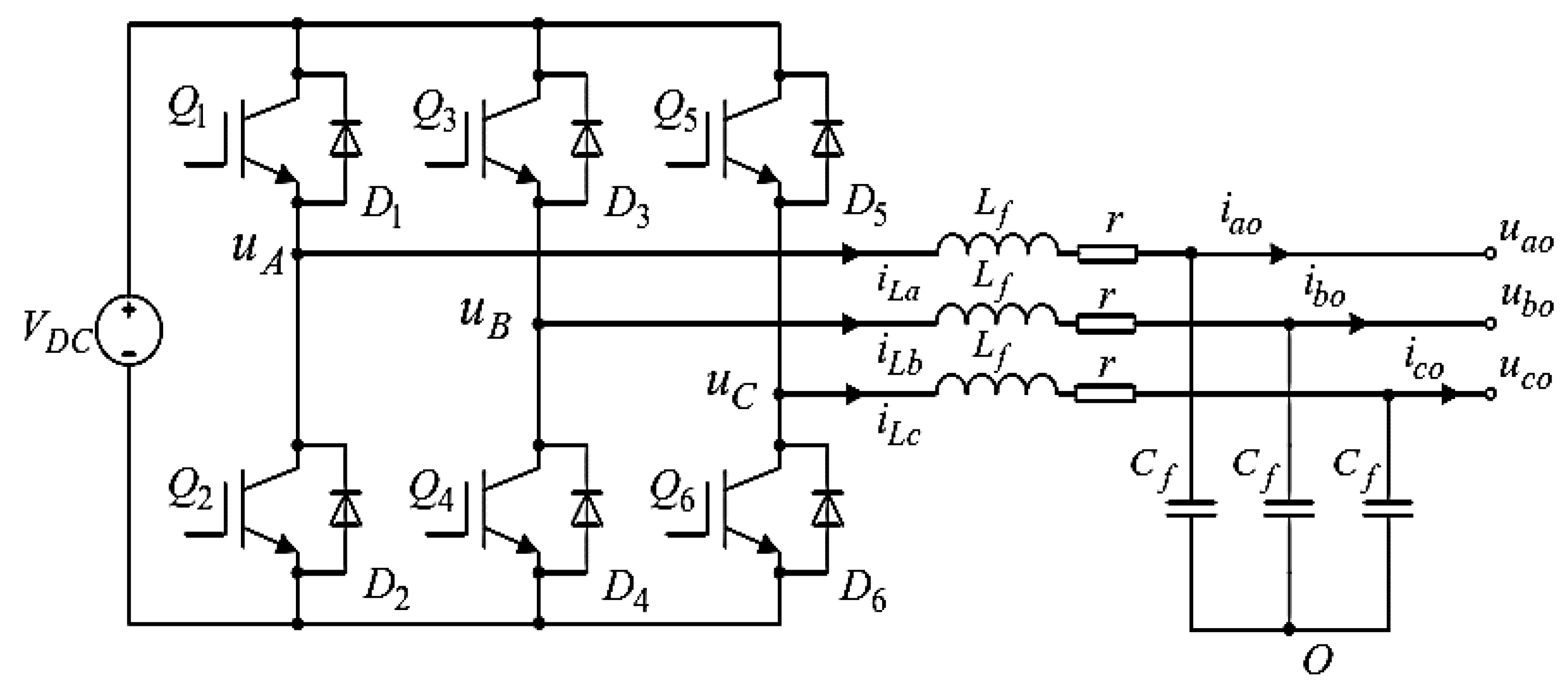
The three-phase voltage-source inverter adopts a three-phase full-bridge topology, as shown in Figure 1. It utilizes a voltage-type three-phase full-bridge inverter circuit. represents the DC-side voltage. The DC-side capacitor C helps stabilize the voltage. The AC voltages outputted by the three-phase bridge arms are , , and . After passing through an LC filter, the voltage outputs are represented as , , and , where represents the filter inductance, represents the equivalent resistance, and represents the filter capacitance. The currents through the three-phase filter inductors are , , and . The output currents to the load side are , , and , with the corresponding three-phase voltages being , , and .
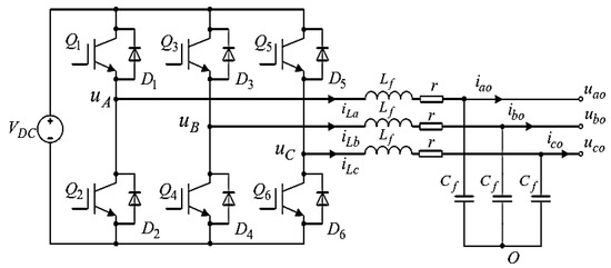
Figure 1.
The structure of a three-phase voltage-source inverter.
In a three-phase stationary coordinate system, analyzing the three-phase AC variables separately for each state increases the difficulty of system control. In practical three-phase symmetrical systems, only two of the AC components are completely independent. Therefore, the Clark transformation is first used to convert the abc stationary coordinate system into the stationary coordinate system, reducing the number of variables in the system. Then, the Park transformation is introduced to convert the AC components within the two-phase into the DC components within the two-phase dq. Equation (1) represents the mathematical model of a three-phase voltage-source inverter in the dq rotating coordinate system.
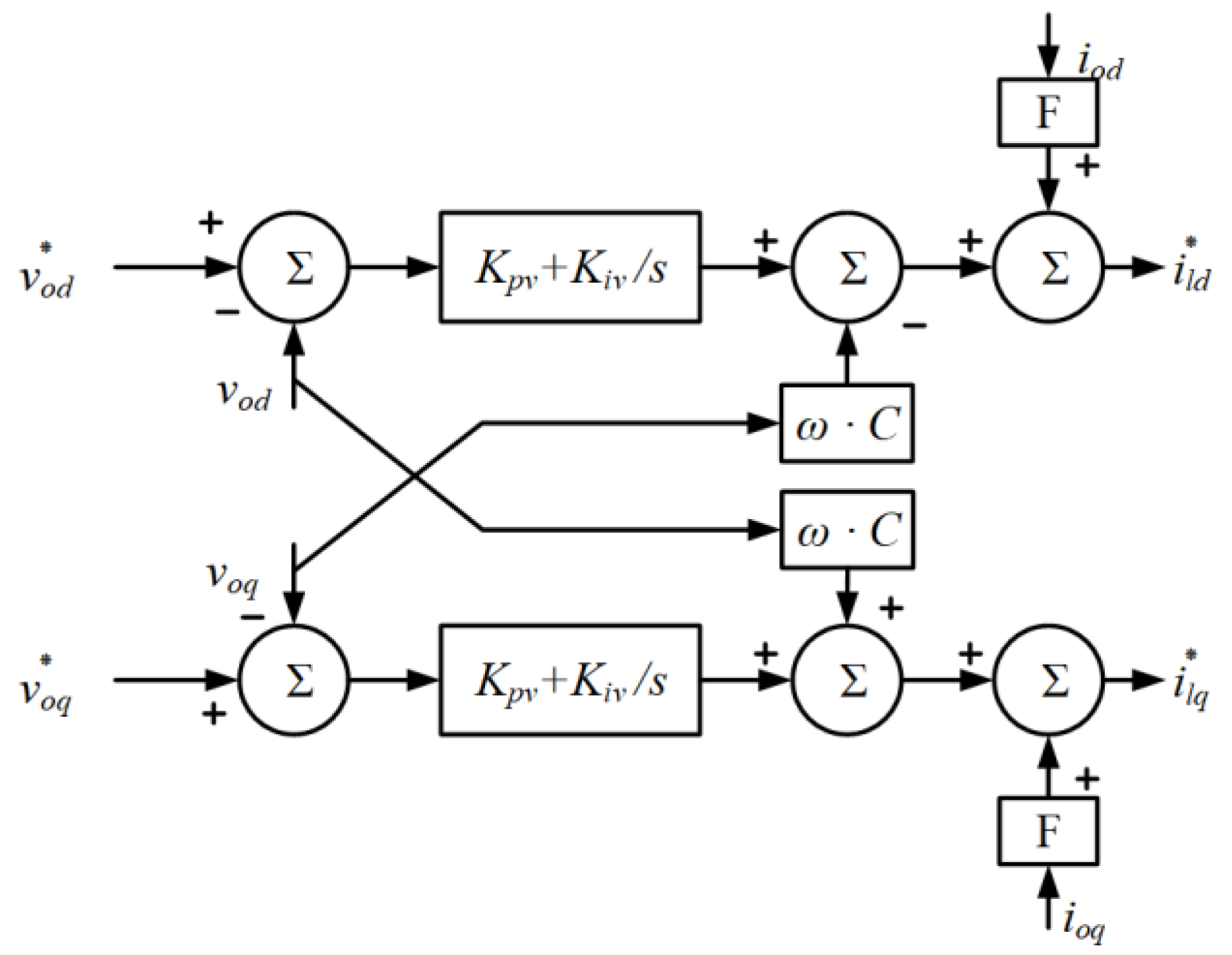
To achieve system stability and synchronize frequency, voltage, and microgrid operation, a dual-loop control system is commonly used. The voltage outer-loop control compares the reference voltage amplitude from droop control with the real-time output voltage of the inverter. Typically, a PI controller regulates the steady-state load voltage and feeds the resulting output into the current inner-loop control.
The voltage control aims to stabilize the DC input voltage of the inverter. Its control block diagram, shown in Figure 2, consists of a closed-loop control with negative feedback and a PI controller, along with a feedforward section. This approach effectively eliminates interference from the forward channel, improving control precision. The use of a PI controller with hysteresis correction enhances control system stability and facilitates debugging.
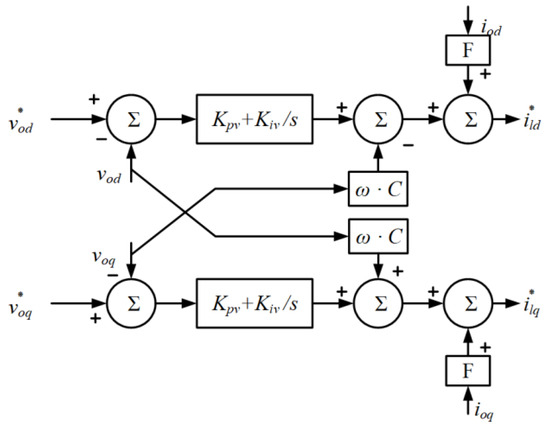
Figure 2.
The block diagram of the voltage control.
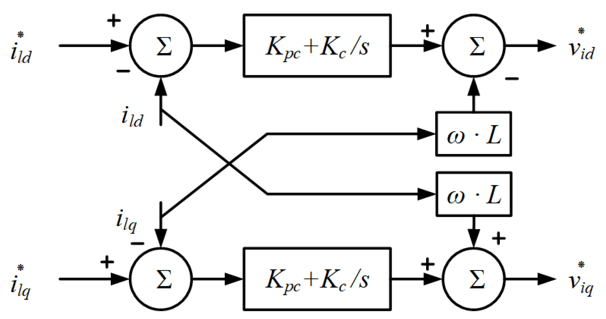
Current control ensures that the inverter’s output current is in phase and at the same frequency as the grid voltage. Its control block diagram, depicted in Figure 3, employs a PI closed-loop control. Similar to voltage control, proportional control enhances system response speed. However, the integral control’s “memory” effect not only guarantees system stability but also significantly improves it.
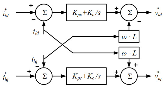
Figure 3.
The block diagram of the current control.
2.2. Droop Control Strategy for Inverters
The droop control method for inverters is a control technique similar to the droop control characteristic of generators. Its main objective is to provide the inverter with reference values for voltage amplitude and frequency, thereby achieving automatic and equitable allocation of output power. There is a strong correlation between active power P and angle , as well as between reactive power Q and voltage . By substituting angle with angular frequency , the droop formula can be derived as follows:
In the equation, m represents the active power droop coefficient, n represents the reactive power droop coefficient, represents the rated voltage angular frequency, represents the rated voltage amplitude, represents the rated active power value, and represents the rated reactive power value.
Based on the droop equation, the droop control process for the inverter can be obtained. Firstly, the average power P and reactive power Q are calculated from the inverter’s voltage output and current output . Then, the composite reference voltage is synthesized using the droop equation, and it is inputted into the voltage P-Q current dual-loop controller as a reference voltage . Finally, the three-phase voltage-source inverter is controlled to operate accordingly.
2.3. Battery Model
In actual microgrids, distributed energy resources cannot be simplified as DC power sources, as they have power limitations. Therefore, a battery model is established to represent the microgrid power supply unit. This approach enables a more realistic reproduction of the system’s state during distribution network restoration.
The battery pack is connected to the DC bus capacitor through a charging and discharging circuit. The topology of the charging and discharging circuit adopts a current-reversible chopper circuit, with the control objective of maintaining the stability of the DC bus capacitor voltage. As the voltage across the capacitor remains constant, the net power flowing into the capacitor is zero. Therefore, the discharge power of the battery is equal to the power output from the inverter to the distribution grid. The inverter adopts a three-phase full-bridge structure and is connected to the grid through an LC filter, providing power to the load. In order to maintain the voltage and frequency stability of the entire distribution system, the inverter system employs droop control. The specific grid-connected topology of the energy storage inverter is as Figure 4.
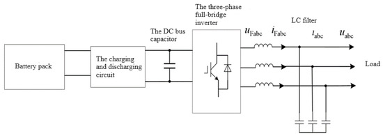
Figure 4.
The topology of the energy storage inverter.
2.4. Droop Control Simulation for Inverters
Conventional droop control is able to adjust voltage amplitude and frequency based on the output power of inverters, while ensuring power quality, under the condition of purely inductive output impedance. In the Matlab/Simulink environment, a simulation model for droop control of a single microsource inverter is constructed to verify the ability of droop control to regulate its own output power while meeting load variations and ensuring power quality characteristics.
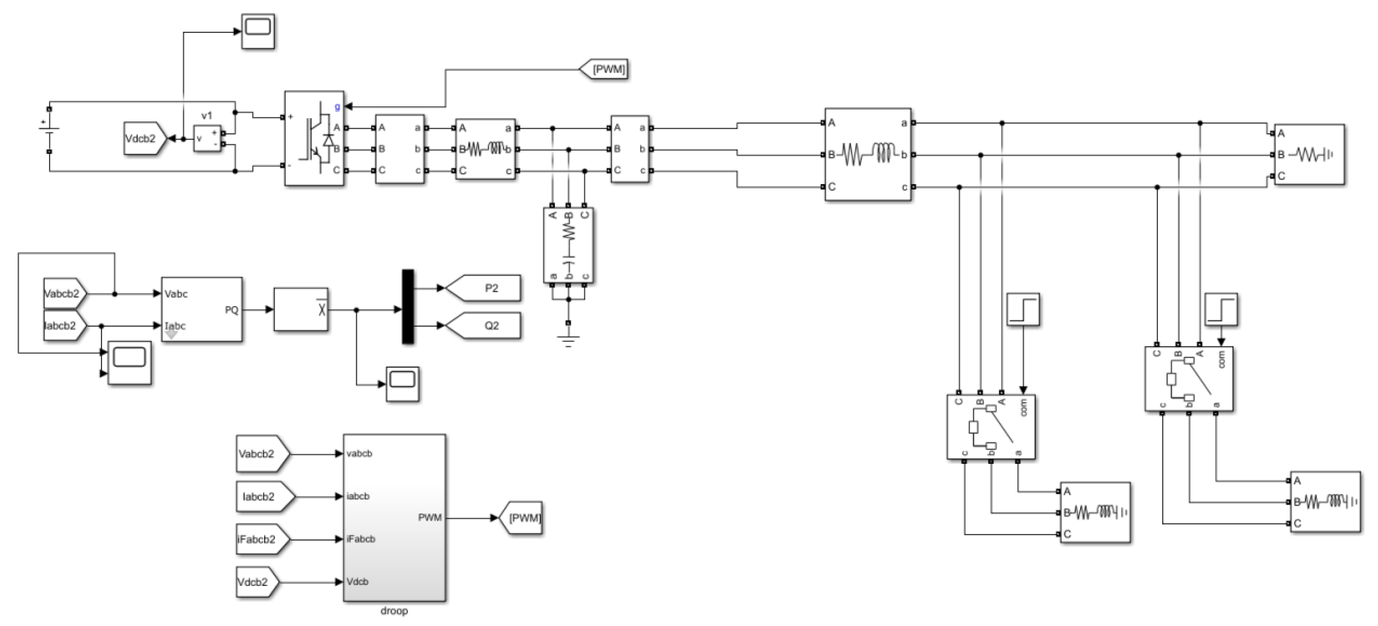
The schematic diagram of the simulation structure for the conventional droop control of microgrid inverters is shown in Figure 5.

Figure 5.
Traditional Droop Control Simulation Model Diagram.
The simulation parameters are provided in Table 1.

Table 1.
Droop control simulation parameters.
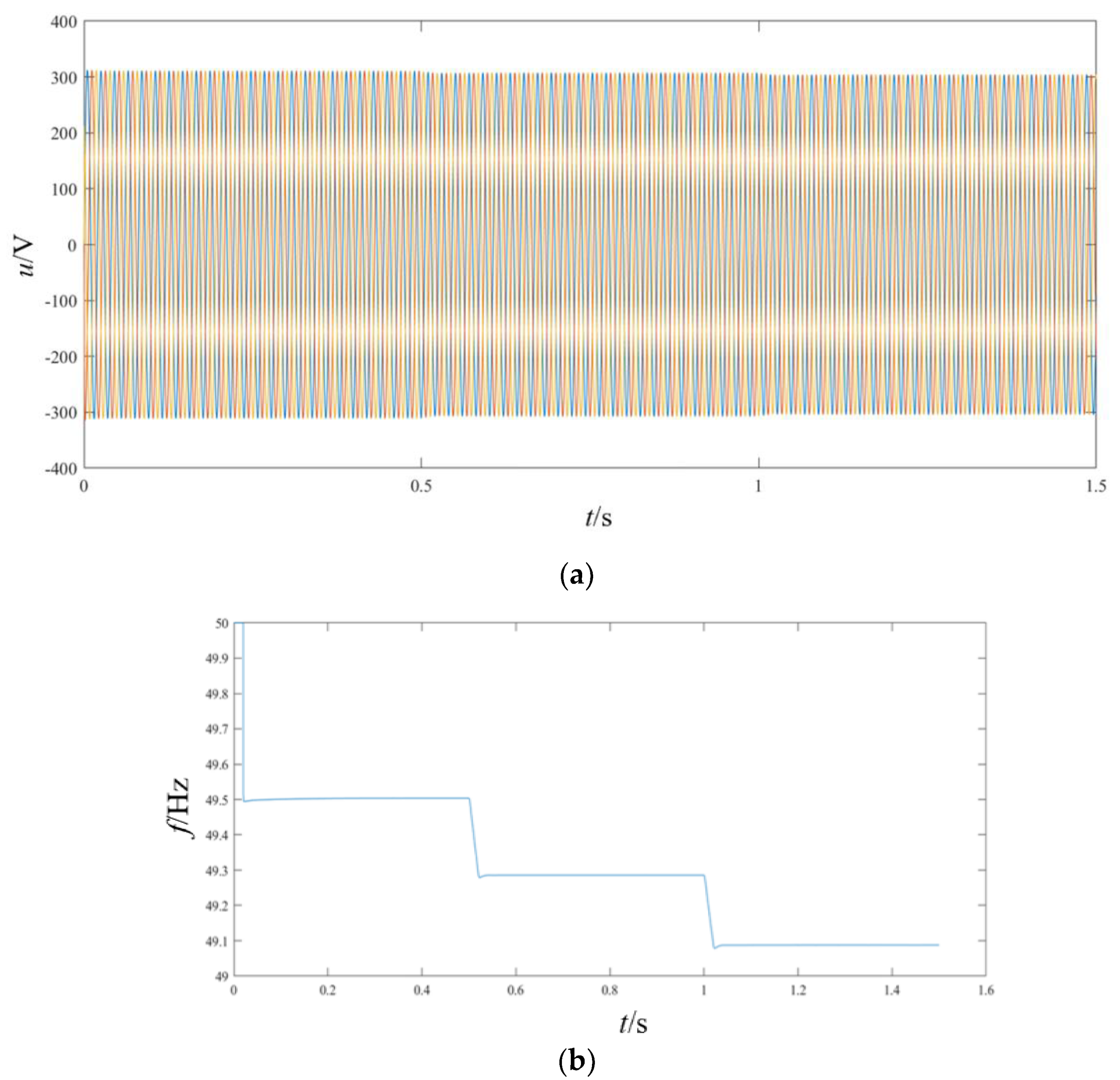
In the above simulation experiment, a local load of 50 kW is applied. At 0.5 s, a load of 25 kW + 8 kVar is introduced, followed by another load of 25 kW + 8 kVar at 1 s. The power variation and power quality of the inverter output using conventional droop control are observed. Figure 6 displays the simulation results.
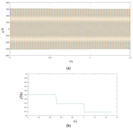
Figure 6.
Simulation results of inverter with conventional droop control. (a) The three-phase voltages waveform. (b) Frequency waveform.
From these results, it can be seen that with the appropriate choice of droop coefficients and closed-loop controller parameters, the conventional droop control method can effectively support the frequency and voltage of the system during islanded operation of the microsource inverter. Additionally, by selecting appropriate droop coefficients, the fluctuations in the output frequency and voltage of the inverter can be controlled within a reasonable range. This control method is simple, offers better control performance, improves the waveform quality of the output voltage and current, enhances system stability, and provides better immunity to interference. However, it should be noted that the traditional droop control is a differential adjustment method, which may introduce certain deviations in the output frequency and voltage amplitudes from their rated values, leading to a degradation in the power quality of the system once it reaches steady-state operation.
3. Research on Improved Droop Control Strategy
3.1. Analysis of Voltage–Frequency Secondary Control Strategy Based on Generator Secondary Frequency Regulation
According to the characteristics of conventional generator secondary regulation, an improved conventional droop control method is proposed. By introducing voltage and frequency feedback loops, the generator is subjected to secondary regulation, thereby achieving secondary regulation of voltage and frequency.
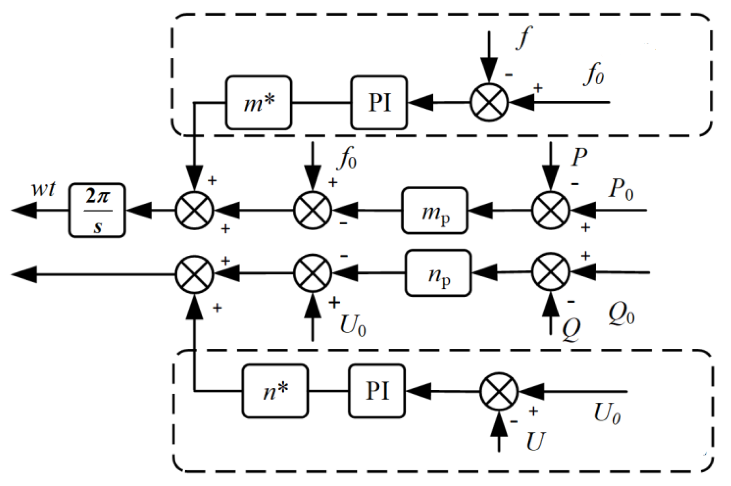
The improved droop control block diagram is depicted in Figure 7.
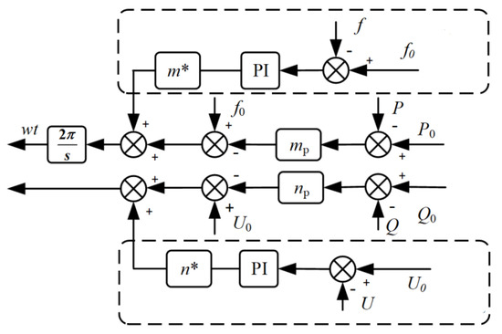
Figure 7.
The schematic diagram of the improved droop controller principle.
Based on Equation (3), it can be observed that the improved droop control method involves forming a closed-loop system by comparing the voltage and frequency deviations detected in the microgrid with their rated values. This closed-loop system is further processed through a PI controller and modified droop coefficients to obtain the desired voltage and frequency setpoints. These setpoints are then added to the voltage and frequency deviations obtained from the droop control, resulting in the final inverter control command. By rearranging the equation and eliminating the terms ‘’ and ‘’, it can be simplified as shown below. When compared to traditional droop control, it is evident that the droop characteristic of conventional control remains fixed, whereas the improved droop control exhibits an adaptive droop characteristic that changes with varying load conditions.
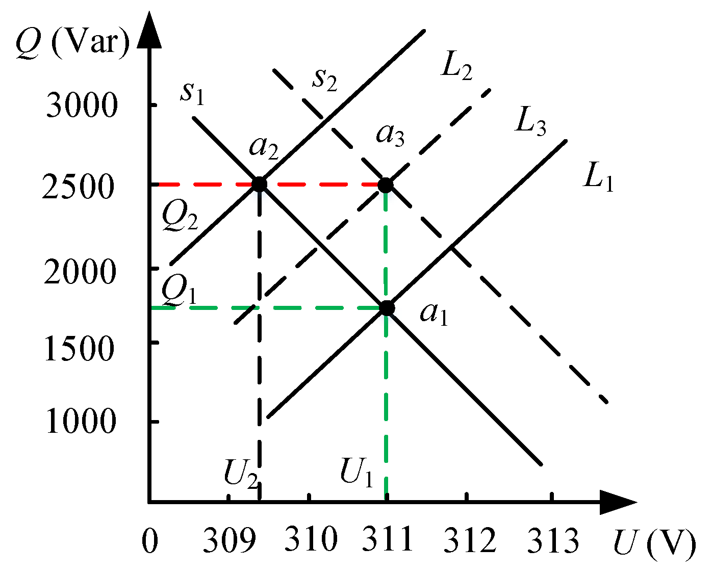
Taking the Q-U control process as an example, the regulation process of the introduced voltage feedback loop is described. The control schematic is shown in Figure 8.
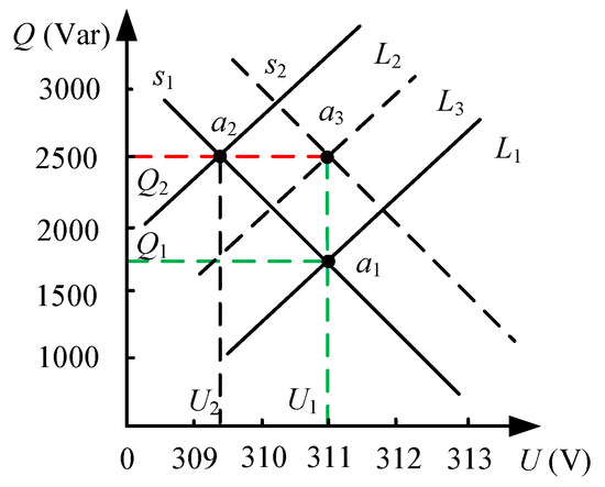
Figure 8.
The improved droop control schematic.
In traditional droop control, when the load changes, the load curve shifts from to , and the system’s stable operating point changes from to . This process is mainly achieved by simulating the primary frequency regulation of a generator through droop control. As the reactive power required by the load changes, the voltage amplitude decreases from to . In the improved droop control, voltage and frequency closed-loop feedback are introduced.
When the load changes, the output power remains constant, causing the curve (denoted as ) to shift to the right to . After the stable operating point changes from to , the voltage amplitude becomes . Compared to conventional droop control, improved droop control can maintain bus voltage and frequency at a stable operating point under the same load changes. By improving droop control, it is possible to increase voltage and frequency while eliminating the effects of calculation errors, noise, and disturbances. This greatly enhances the stability of voltage and frequency, ensuring they remain within the rated range.
The Simulink simulation model is constructed as shown in Figure 9.
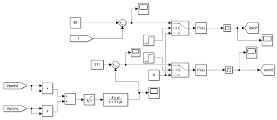
Figure 9.
The Simulink simulation model for secondary control.
3.2. Comparative Simulation Experiments of Improved Droop Control for Inverters
Validation of the theoretically improved droop control method was performed using the MATLAB(R2021a)/Simulink simulation platform. A control model was constructed and experimental verification was conducted. Inverter droop control simulation parameters are shown in Table 2.
Table 2.
Inverter droop control simulation parameters.
In the comparative simulations, the simulation parameters for primary and secondary control are identical. Initially, a 50 kW load is applied, followed by the addition of a 25 kW + 8 kVar load after 0.5 s. The output power and power quality of the inverter are observed.
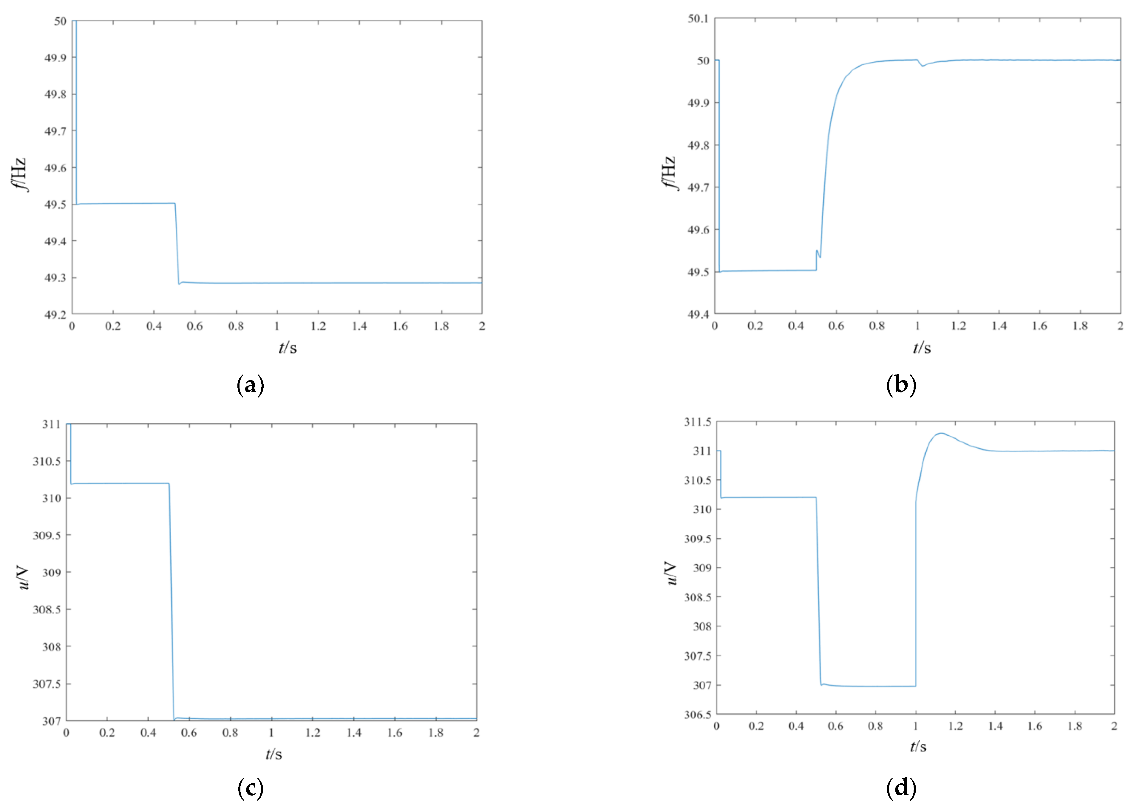
For the secondary simulation scenario, the following settings are applied: Initially, a 50 kW load is applied, followed by the addition of a 25 kW + 8 kVar load after 0.5 s. The microgrid-distributed power inverter adopts a droop control strategy. At 0.5 s, frequency secondary control is introduced to maintain the system frequency at 50 Hz, completing the frequency secondary control. At 1 s, voltage secondary control is introduced to stabilize the system voltage, completing the voltage secondary control. The simulation results are shown in Figure 10.
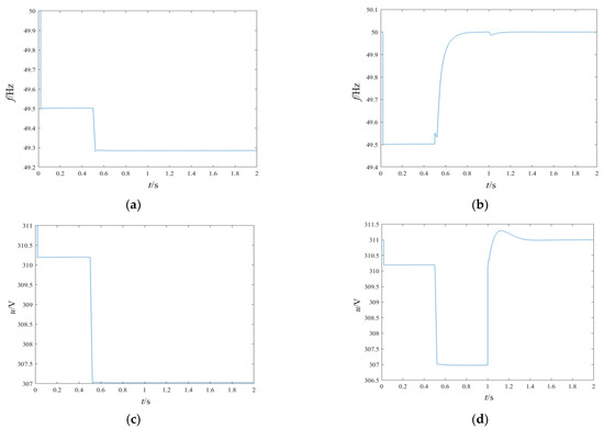
Figure 10.
Comparison of waveforms before and after introducing secondary control. (a) Frequency waveform of the microgrid before adding secondary control. (b) Frequency waveform of the microgrid after adding secondary control. (c) Effective voltage waveform of the microgrid before adding secondary control. (d) Effective voltage waveform of the microgrid after adding secondary control.
From Figure 10a,b, it can be observed that when using the improved droop control with frequency secondary control, the microgrid frequency can quickly adjust back to 50 Hz when the load increases. This demonstrates the completion of secondary frequency regulation. From Figure 10c,d, it can be observed that when using the improved droop control with voltage secondary control, at 3 s after the load increase, voltage secondary control is introduced. This adjusts the microgrid’s RMS voltage to 220 V, completing the secondary voltage regulation of the system.
4. Case Study Analysis of Dynamic Microgrid Secondary Control
The actual process of power distribution network restoration is not as simple as a few loads in previous independent models. In this section, a local restoration model of a distribution network with a voltage level of 10 kV is constructed based on specific data from the IEEE 33-node system.
Due to the time-consuming nature (over 30 min) of running the Matlab/Simulink simulation for the entire IEEE 33-node network, a portion of the IEEE 33-node system (nodes 9–18) is selected for local simulation analysis.
4.1. Simulation Analysis for Load Restoration
After a fault, all nodes in the distribution network will be disconnected, and the distribution network will be divided into several smaller microgrids. Each microgrid will reestablish connections of loads through cascading connections from distributed power sources. In this model, the charging and discharging circuit of the battery limits the voltage across the capacitor to around 900 V. After three-phase inversion, the output is a three-phase AC voltage with an amplitude of 311 V. This voltage then passes through a 380/10.5 kV Yn-Yn transformer, resulting in a three-phase AC voltage with an amplitude of 10.5 kV.
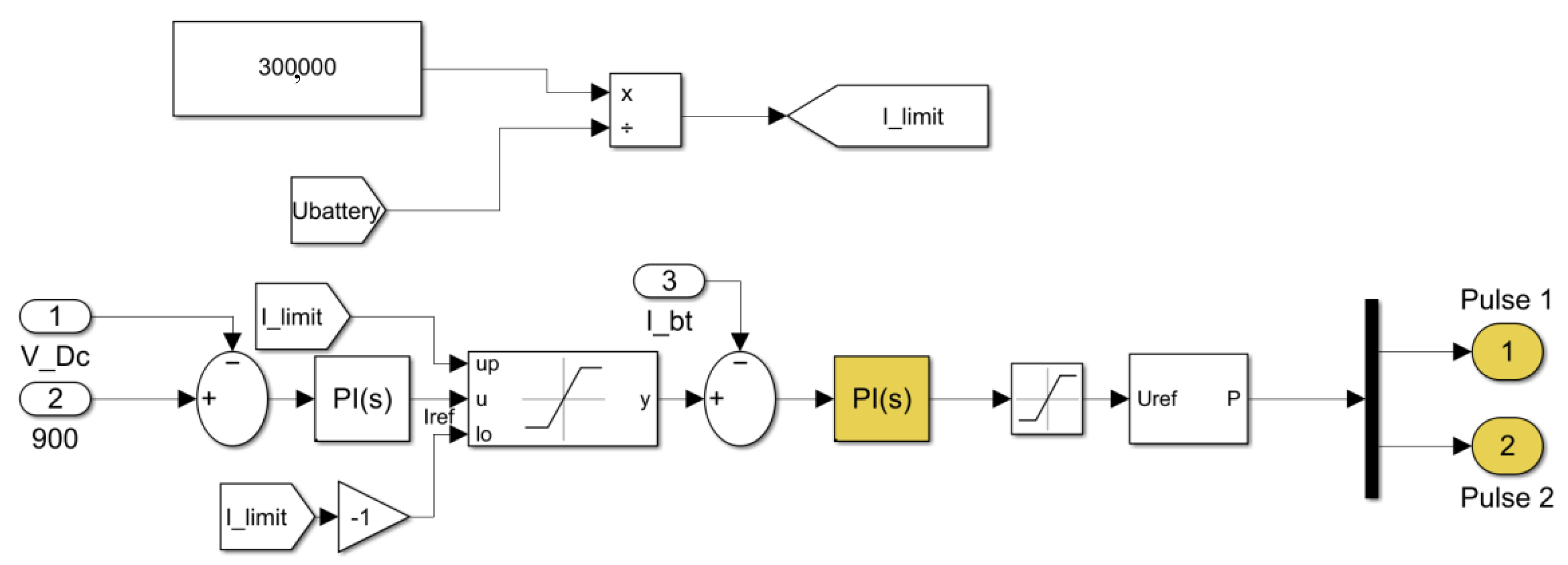
In order to strictly limit the output power of the battery, a power limiter is incorporated within the dual-loop controller of the battery’s charging and discharging circuit. This power limiter restricts the total power output of the battery by limiting the amplitude of the input current to the controller, based on the equation under DC conditions. The power limiter, as shown in Figure 11, is temporarily set with a maximum output power value of 300 kW.
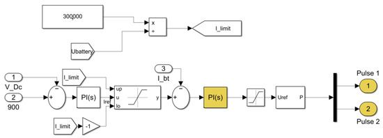
Figure 11.
Dual-loop controller with output power limitation.
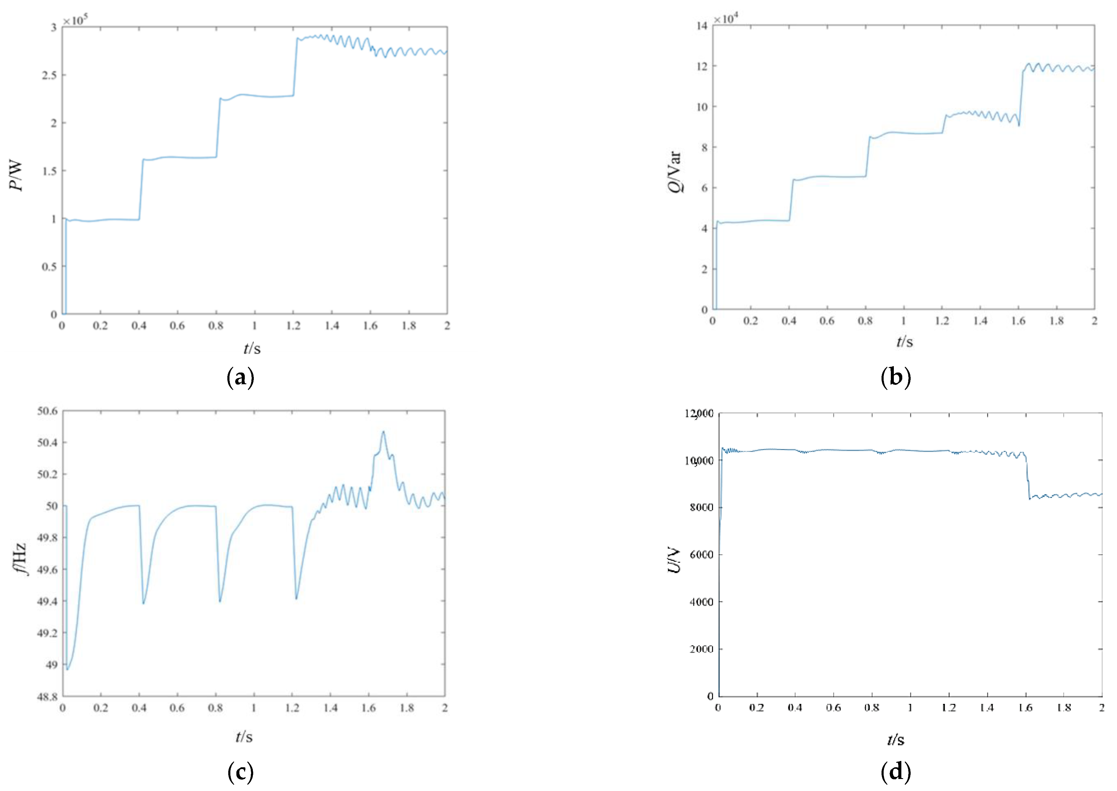
In Simulink, select a battery pack with a rated voltage of 300 V and a rated capacity of 1000 Ah. Build the charging and discharging circuit, the inverter circuit, and their corresponding control loops. Restore load 18 at t = 0 s, load 17 at t = 0.4 s, load 16 at t = 0.8 s, load 15 at t = 1.2 s, and load 14 at t = 1.6 s. Figure 12 presents the simulation results for the system nodes.
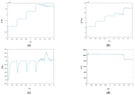
Figure 12.
Simulation of droop control with limited output power. (a) Active power. (b) Reactive power. (c) Frequency. (d) Voltage amplitude at the high-voltage side of the transformer.
Based on the voltage amplitude graph, it can be observed that due to the limited maximum output power of 300 kW, after the fourth load is connected at t = 1.2 s, the total load connected to the grid is 270 kW. However, due to the line impedance and transformer impedance consuming a portion of power, an unstable state has already emerged after t = 1.2 s. The three-phase voltage, active power, and reactive power are all oscillating. After t = 1.6 s, the fifth load is connected, and the total rated power of the loads amounts to 390 kW. The capacitor at the battery terminals no longer provides a 900 V DC voltage and, as the discharge process progresses, the voltage keeps decreasing, eventually oscillating within a certain range. Therefore, it can be seen that adding droop control with secondary control to the battery is unable to maintain the load in a temporary stable state when there is insufficient power. Once the load exceeds the rated value, the system immediately collapses, thereby preventing the microgrid from being in an overloaded condition.
It can be observed that after t = 1.6 s, the system becomes unstable, with significant distortion in the three-phase voltage and large oscillations in the active and reactive power, according to the formula for the power transmission limit of the line:
Based on the actual parameters of the circuit, the power transmission limit is calculated to be approximately 340 kW. This is the reason for the voltage distortion and instability. In practical applications, the power of the battery is generally not as large, so this situation is unlikely to occur. The biggest factor affecting the power transmission limit is the filtering inductance of the line. However, when the filtering inductance is adjusted to a low value, the filtering effect deteriorates, leading to distortion as well. Therefore, the parallel inverter configuration is chosen to distribute the power evenly between the two inverters.
4.2. Simulation Analysis of 10 kV Distribution Network Restoration
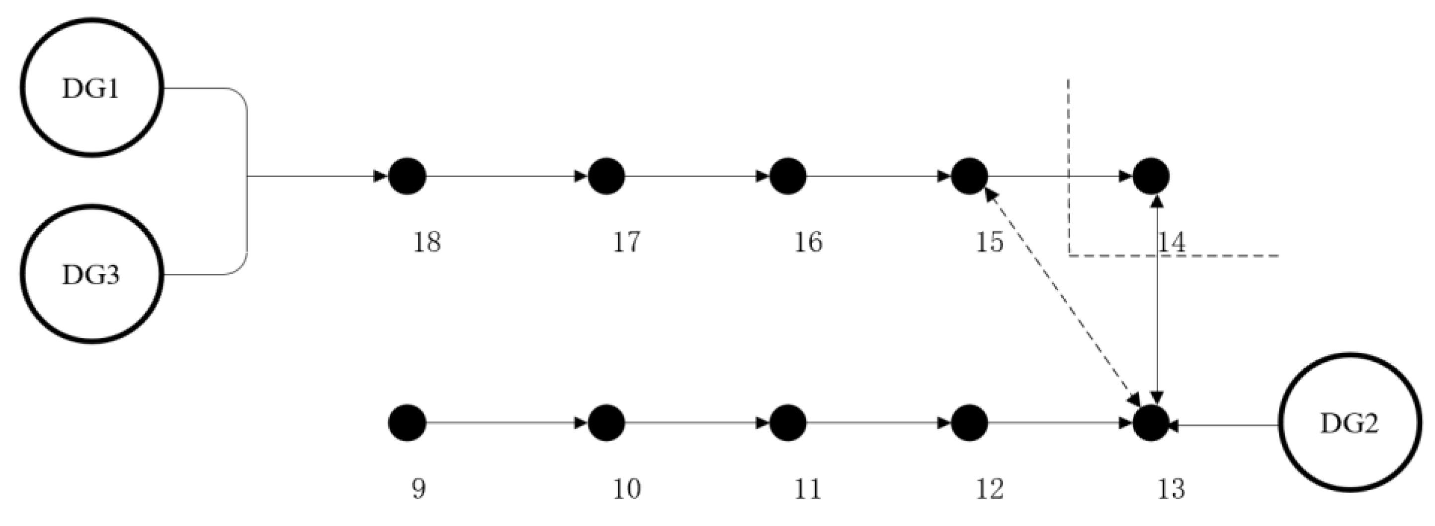
The specific simulation conditions are as follows: Distributed Generators (DG1, DG3) operate in parallel through droop-controlled inverters. The inverters convert the 900 V DC voltage from the battery into 220 V three-phase AC power. Then, the energy is delivered to the 10 kV distribution network through a 380 V/10.5 kV transformer. Restoration is performed step by step on nodes 18, 17, 16, 15, and 14 in the IEEE33 network, with a load interval of 0.4 s. Simultaneously, Distributed Generator DG2, using droop-controlled inverters and transformers, restores nodes 13, 12, 11, 10, and 9 step by step, with a load interval of 0.4 s, as shown in Figure 4, Figure 5, Figure 6, Figure 7 and Figure 8. Once both microgrids reach a stable state, they are merged to form a larger microgrid. Finally, based on the parameters of the merged grid, a portion of the load is shed at t = 4 s to meet the requirements of power quality.
It should be noted that during the operation of the merged microgrid, if there is a significant phase difference between the voltages on both sides, large oscillations may occur, causing irreversible damage to various components. Therefore, a synchronization check operation should be performed before merging the grids. This is achieved by measuring and comparing the phases of the microgrids on both sides. If both microgrids have reached a stable state and the phase difference between them is within a certain range, the closing operation is performed to merge the two microgrids together. The phase difference range in the simulation is set to within −0.5~0.5 rad. The schematic diagram of the comprehensive restoration of the distribution network nodes is shown in Figure 13, and the simulation results are shown in Figure 14.

Figure 13.
Comprehensive restoration plan of the distribution network.

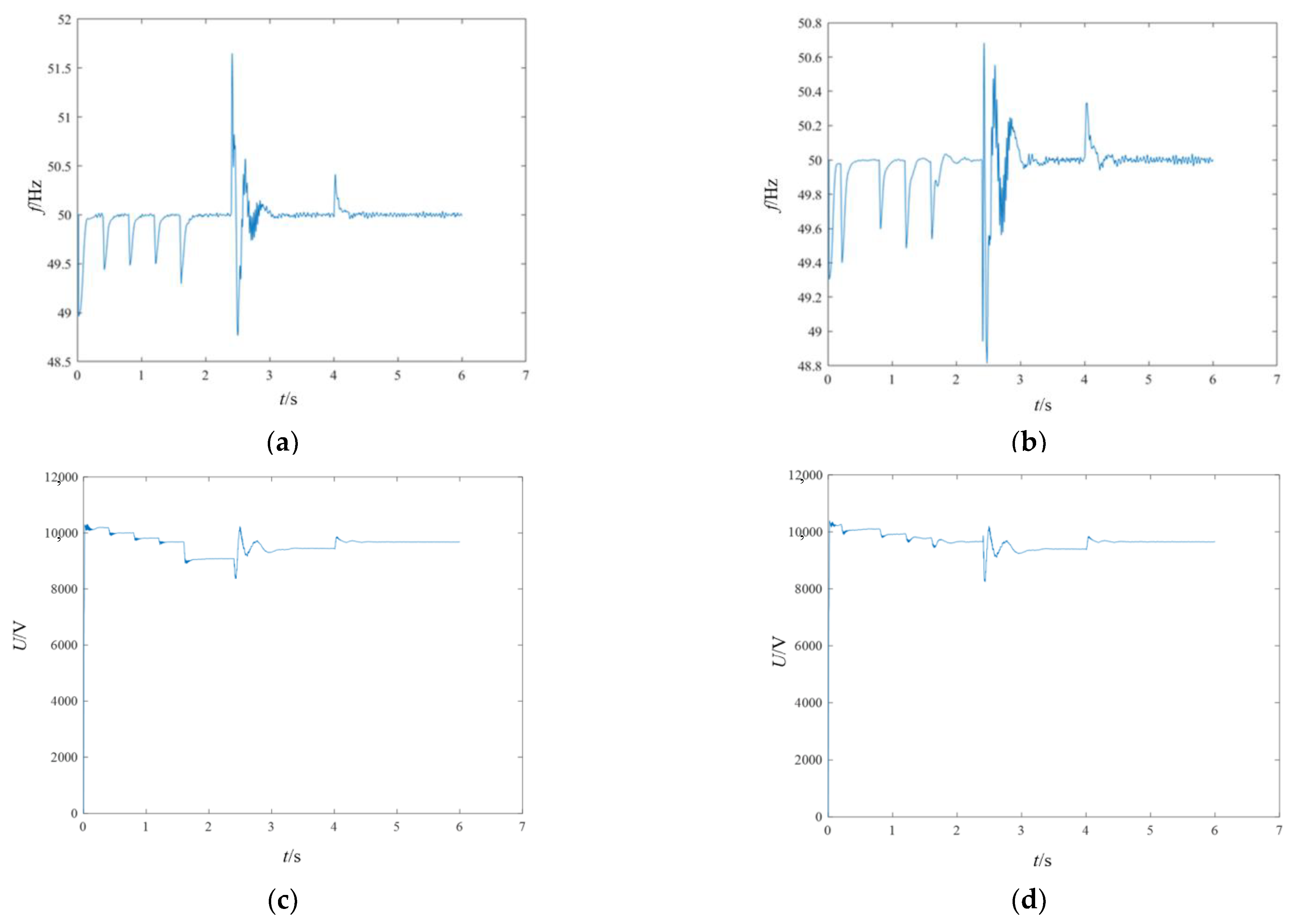
Figure 14.
Comprehensive restoration plan of the distribution network. (a) Frequency at DG1 and DG2 sides. (b) Frequency at DG3 side. (c) RMS voltage at DG1 and DG2 sides. (d) RMS voltage at DG3 side.
Based on the simulation results, it can be observed that at t = 2.4 s, the two microgrids are connected together. However, due to the phase mismatch, there is a transient restoration process after the closing operation. After the transient process ends, the voltage and frequency tend to settle at a steady state. The active and reactive powers are redistributed to achieve a new steady state. Within the allowable power range of the battery, stable operation of the inverters in parallel can be ensured.
After the integration of the microgrids, the voltage magnitude at the end of the line is only 9.3 kV, which does not meet the range of 0.95–1.05 times the rated voltage. Load 14 is disconnected, resulting in a decrease in power consumed by the line impedance. As a result, the voltage at the end of the line rebounds to 9.6 kV, meeting the requirements for power quality. Adjusting the load enables the microgrid to quickly enter a new steady state, thus demonstrating the rationality and effectiveness of the proposed control strategy in this paper.
5. Conclusions
This paper primarily investigates the control strategy and results of voltage–frequency secondary control in dynamic boundary microgrid topology changes. Firstly, a mathematical model of microgrid inverters based on droop control is constructed. Then, inspired by the generator secondary frequency control strategy, an improved secondary control method based on droop control is implemented. Finally, we focus on modeling distributed power sources and constructing a 10 kV distribution network model using the standard IEEE 33-node distribution network test system data. A model based on the mentioned improved droop control is designed and implemented for voltage–frequency secondary control during post-fault recovery in practical distribution networks. The reasons for establishing this model are discussed, and various issues leading to network instability are identified and analyzed during the simulation process. Different solutions are provided for different problems. Lastly, a microgrid simulation model is designed to incorporate various dynamic boundary topological changes, and a relatively stable control result is obtained, thus validating the effectiveness of the proposed strategies. In real-world microgrids, the phenomenon of voltage distortion in the output of inverters caused by harmonic currents from nonlinear loads needs to be addressed. Therefore, further research is needed to develop control strategies that can suppress the distortion of the output voltage.
Author Contributions
Data curation, G.L.; formal analysis, J.S.; funding acquisition, Y.W. and L.X.; methodology, J.S. and D.L.; project administration, L.X.; resources, N.M. and G.L; software, D.L.; supervision, C.C.; validation, Z.L. and Z.X.; visualization, Z.L.; writing—original draft, J.S.; writing—review and editing, C.C. All authors have read and agreed to the published version of the manuscript.
Funding
This work is supported by the Science and Technology Project of China Southern Power Grid Co., Ltd. (No. 090000KK52222158).
Data Availability Statement
The data presented in this study are available upon request from the corresponding author. The data are not publicly available due to confidentiality agreements.
Conflicts of Interest
Authors Yijun Wang, Nan Ma, Guowei Liu and Lisheng Xin were employed by the company Shenzhen Power Supply Co. Ltd. The remaining authors declare that the research was conducted in the absence of any commercial or financial relationships that could be construed as a potential conflict of interest. The authors declare that this study received funding from Science and Technology Project of China Southern Power Grid Co., Ltd. The funder was not involved in the study design, collection, analysis, interpretation of data, the writing of this article or the decision to submit it for publication.
References
- Wang, Z.; Wang, J. Self-Healing Resilient Distribution Systems Based on Sectionalization Into Microgrids. IEEE Trans. Power Syst. 2015, 30, 3139–3149. [Google Scholar] [CrossRef]
- Tang, F.; Guerrero, J.M.; Vasquez, J.C.; Wu, D.; Meng, L.X. Distributed Active Synchronization Strategy for Microgrid Seamless Reconnection to the Grid Under Unbalance and Harmonic Distortion. IEEE Trans. Smart Grid 2015, 6, 2757–2769. [Google Scholar] [CrossRef]
- 15472-2008; IEEE Application Guide for IEEE Std 1547(TM), IEEE Standard for Interconnecting Distributed Resources with Electric Power Systems. IEEE Standards Association: Piscataway, NJ, USA, 2009; pp. 1–217. [CrossRef]
- Zhang, J.; Ding, L.; Lu, X.; Tang, W. A Novel Real-Time Control Approach for Sparse and Safe Frequency Regulation in Inverter Intensive Microgrids. IEEE Trans. Ind. Appl. 2023, 59, 5550–5558. [Google Scholar] [CrossRef]
- Khayat, Y.; Shafiee, Q.; Heydari, R.; Naderi, M.; Dragičević, T.; Simpson-Porco, J.W.; Dörfler, F.; Fathi, M.; Blaabjerg, F.; Guerrero, J.M.; et al. On the Secondary Control Architectures of AC Microgrids: An Overview. IEEE Trans. Power Electron. 2020, 35, 6482–6500. [Google Scholar] [CrossRef]
- Nassar, M.E.; Salama, M.M.A. Adaptive Self-Adequate Microgrids Using Dynamic Boundaries. IEEE Trans. Smart Grid 2016, 7, 105–113. [Google Scholar] [CrossRef]
- Kim, Y.J.; Wang, J.; Lu, X. A Framework for Load Service Restoration Using Dynamic Change in Boundaries of Advanced Microgrids With Synchronous-Machine DGs. IEEE Trans. Smart Grid 2018, 9, 3676–3690. [Google Scholar] [CrossRef]
- Ma, Y.; Hu, X.; Yin, H.; Zhu, L.; Su, Y.; Wang, F.; Tolbert, L.M.; Liu, Y. Real-Time Control and Operation for a Flexible Microgrid with Dynamic Boundary. In Proceedings of the 2018 IEEE Energy Conversion Congress and Exposition (ECCE), Portland, OR, USA, 23–27 September 2018; pp. 5158–5163. [Google Scholar]
- Bai, X.; Miao, H.; Zeng, C. Improved Droop Control Strategy for Reactive Power Sharing of Parallel Inverters In Low-Voltage Microgrid. In Proceedings of the 2019 IEEE Innovative Smart Grid Technologies—Asia (ISGT Asia), Chengdu, China, 21–24 May 2019; pp. 2538–2543. [Google Scholar]
- Romero, M.E.; Seron, M.M. Ultimate Boundedness of Voltage Droop Control With Distributed Secondary Control Loops. IEEE Trans. Smart Grid 2019, 10, 4107–4115. [Google Scholar] [CrossRef]
- Tian, L.; Tang, Z.; Tian, C.; Zhu, R. Research of Microgrid Seamless Switching Based on State Follower. Power Syst. Technol. 2017, 41, 1285–1290. [Google Scholar]
- Kai, F.; JianLin, L.; Dong, H. Study on the control strategy of PV-energy storage microgrid working in islanded mode. Appl. Mech. Mater. 2014, 672–674, 79–85. [Google Scholar] [CrossRef]
- Zhang, L.; Zheng, H.; Hu, Q.G.; Su, B.; Lyu, L. An Adaptive Droop Control Strategy for Islanded Microgrid Based on Improved Particle Swarm Optimization. IEEE Access 2020, 8, 3579–3593. [Google Scholar] [CrossRef]
- Yeole, S.S.; Gujarathi, G.S.; Pande, A.S.; Pawar, S.S.; Thorat, P.A.; Amol, S.P.; Changan, G.S. Method for controlling distributed generations through active power sharing and self-frequency recovery in islanded microgrid, involves recovering frequency deviation by distributed generations through self-frequency recovery control. IN202221065281-A.
- Zhu, Y.X.; Zhuo, F.; Liu, B.Q.; Yi, H. An Enhanced Load Power Sharing Strategy for Low-voltage Microgrids Based on Inverse-droop Control Method. In Proceedings of the International Power Electronics Conference (IPEC-ECCE-ASIA), Hiroshima, Japan, 18–21 May 2014; pp. 3546–3552. [Google Scholar]
- Dou, Y.; Chi, M.; Liu, Z.W.; Wen, G.; Sun, Q. Distributed Secondary Control for Voltage Regulation and Optimal Power Sharing in DC Microgrids. IEEE Trans. Control Syst. Technol. 2022, 30, 2561–2572. [Google Scholar] [CrossRef]
- Lou, G.; Gu, W.; Xu, Y.; Cheng, M.; Liu, W. Distributed MPC-Based Secondary Voltage Control Scheme for Autonomous Droop-Controlled Microgrids. IEEE Trans. Sustain. Energy 2017, 8, 792–804. [Google Scholar] [CrossRef]
- Du, Y.; Lu, X.; Tang, W. Accurate Distributed Secondary Control for DC Microgrids Considering Communication Delays: A Surplus Consensus-Based Approach. IEEE Trans. Smart Grid 2022, 13, 1709–1719. [Google Scholar] [CrossRef]
- Li, X.; He, J.; Li, X.; Wen, C. Robust Distributed Secondary Control for AC Microgrids With Time-Varying Delay. IEEE Trans. Control Syst. Technol. 2023, 31, 937–944. [Google Scholar] [CrossRef]
- Guerrero, J.M.; de Vicuña, L.G.; Matas, J.; Castilla, M.; Miret, J. Output impendance design of parallel-connected UPS inverters with wireless load-sharing control. IEEE Trans. Ind. Electron. 2005, 52, 1126–1135. [Google Scholar] [CrossRef]
- Guerrero, J.M.; Matas, J.; de Vicuña, L.G.; Castilla, M.; Miret, J. Decentralized control for parallel operation of distributed generation inverters using resistive output impedance. IEEE Trans. Ind. Electron. 2007, 54, 994–1004. [Google Scholar] [CrossRef]
- Wu, J.; Jin, X.; Yin, T.; Liu, Q.; Yan, S.C. Research on power quality control of grid-connected microgrid based on distributed generation. Int. J. Ambient Energy 2019, 43, 1236–1240. [Google Scholar] [CrossRef]
- Guerrero, J.M.; Chandorkar, M.; Lee, T.L.; Loh, P.C. Advanced Control Architectures for Intelligent Microgrids-Part I: Decentralized and Hierarchical Control. IEEE Trans. Ind. Electron. 2013, 60, 1254–1262. [Google Scholar] [CrossRef]
- Meng, X.; Liu, J.J.; Liu, Z. A Generalized Droop Control for Grid-Supporting Inverter Based on Comparison Between Traditional Droop Control and Virtual Synchronous Generator Control. IEEE Trans. Power Electron. 2019, 34, 5416–5438. [Google Scholar] [CrossRef]


Disclaimer/Publisher’s Note: The statements, opinions and data contained in all publications are solely those of the individual author(s) and contributor(s) and not of MDPI and/or the editor(s). MDPI and/or the editor(s) disclaim responsibility for any injury to people or property resulting from any ideas, methods, instructions or products referred to in the content. |
© 2024 by the authors. Licensee MDPI, Basel, Switzerland. This article is an open access article distributed under the terms and conditions of the Creative Commons Attribution (CC BY) license (https://creativecommons.org/licenses/by/4.0/).