


Properties of Carbon Fibers as Supercapacitor Electrodes via Electrospinning Using a Blending Solution of Polyacrylonitrile and Bisphenol A


Abstract
:1. Introduction

| Material | Electrolyte | C (F/g) | Cycle Stability | Ref. |
|---|---|---|---|---|
| Carbon nanotubes | 6 M KOH (aq.) | 56.04 | 85.4% (10,000 cycle) | [48] |
| Graphene | 6 M KOH (aq.) | 180 | 79.6% (4000 cycle) | [49] |
| Activated carbon | PVA/IL/H3PO4 (s) | 106 | 95% (3000 cycle) | [50] |
| Carbon nanofibers | 2 M KOH (aq.) | 155 | 91% (5000 cycle) | [51] |
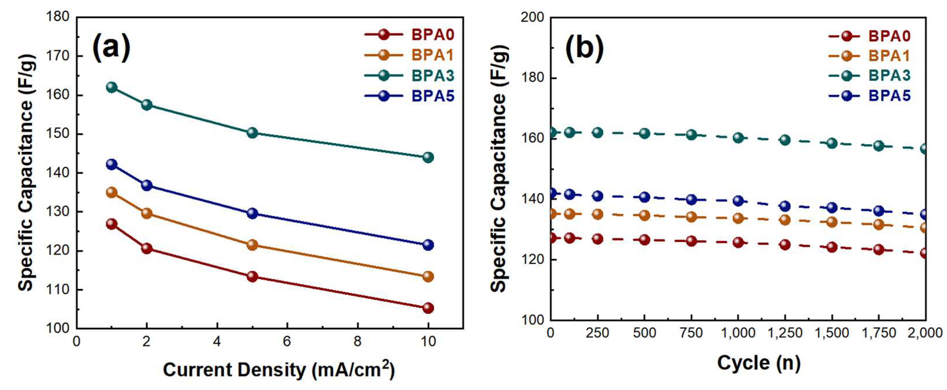
| BPA3 | 6 M KOH (aq.) | 176 | 96.8% (2000 cycle) | This work |
2. Experimental
2.1. Materials
2.2. Preparation of Carbon Nanofibers via Electrospinning
2.3. Characterization
2.4. Electrochemical Test
3. Results and Discussion
4. Conclusions
Supplementary Materials
Author Contributions
Funding
Data Availability Statement
Conflicts of Interest
References
- Luo, B.; Wang, B.; Li, X.; Jia, Y.; Liang, M.; Zhi, L. Graphene-Confined Sn Nanosheets with Enhanced Lithium Storage Capability. Adv. Mater. 2012, 24, 3538–3543. [Google Scholar] [CrossRef]
- Chu, S.; Majumdar, A. Opportunities and challenges for a sustainable energy future. Nature 2012, 488, 294–303. [Google Scholar] [CrossRef]
- Arico, A.S.; Bruce, P.; Scrosati, B.; Tarascon, J.A.; Schalkwijk, W. Nanostructured materials for advanced energy conversion and storage devices. Nat. Mater. 2005, 4, 366–377. [Google Scholar] [CrossRef]
- Lemian, D.; Bode, F. Battery-Supercapacitor Energy Storage Systems for Electrical Vehicles: A Review. Energies 2022, 15, 5683. [Google Scholar] [CrossRef]
- Mahapatra, A.; Mandal, M.; Mahapatra, A.D.; Anilkumar, V.; Nawrocki, J.; Chavan, R.D.; Yadav, P.; Prochowicz, D. Mechanochemically-Assisted Synthesis of 3D, 2D and quasi 2d Lead Halide Perovskites for Supercapacitor Application. Mater. Adv. 2024. [Google Scholar] [CrossRef]
- Burke, A. Ultracapacitors: Why, how and where is the technology. J. Power Sources 2000, 91, 37–50. [Google Scholar] [CrossRef]
- Miller, J.R.; Simon, P. Electrochemical Capacitors for Energy Management. Science 2008, 321, 651–652. [Google Scholar] [CrossRef]
- Frachowiak, E. Carbon materials for supercapacitor application. Phys. Chem. Chem. Phys. 2007, 9, 1774–1785. [Google Scholar] [CrossRef]
- Fayon, P.; Thomas, J.M.H.; Trewin, A. Structure and Properties of a Nanoporous Supercapacitor. J. Phys. Chem. C 2016, 120, 25880–25891. [Google Scholar] [CrossRef]
- Portet, C.; Taberna, P.L.; Simon, P.; Flahaut, E.; Laberty-Robert, C. High power density electrodes for Carbon supercapacitor applications. Electrochimica 2005, 50, 4174–4181. [Google Scholar] [CrossRef]
- Brousse, T.; Crosnier, O.; Bélanger, D.; Long, J.W. Capacitive and Pseudocapacitive Electrodes for Electrochemical Capacitors and Hybrid Devices. In Metal Oxides in Supercapacitors; Elsevier: Amsterdam, The Netherlands, 2017; pp. 1–24. [Google Scholar]
- Ning, P.; Duan, X.; Ju, X.; Lin, X.; Tong, X.; Pan, X.; Wang, T.; Li, Q. Facile synthesis of carbon nanofibers/MnO2 nanosheets as high-performance electrodes for asymmetric supercapacitors. Electrochim. Acta 2016, 210, 754–761. [Google Scholar] [CrossRef]
- Sun, Y.; Guo, S.; Li, W.; Pan, J.; Fernandez, C.; Senthil, R.A.; Sun, X. A green and template-free synthesis process of superior carbon material with ellipsoidal structure as enhanced material for supercapacitors. J. Power Sources 2018, 405, 80–88. [Google Scholar] [CrossRef]
- Lim, E.; Jo, C.; Lee, J. A mini review of designed mesoporous materials for energy-storage applications: From electric double-layer capacitors to hybrid supercapacitors. Nanoscale 2016, 8, 7827–7833. [Google Scholar] [CrossRef] [PubMed]
- Sugimoto, W.; Makino, S.; Mukai, R.; Tatsumi, Y.; Fukuda, K.; Takasu, Y.; Yamauchi, Y. Synthesis of ordered mesoporous ruthenium by lyotropic liquid crystals and its electrochemical conversion to mesoporous ruthenium oxide with high surface area. J. Power Sources 2012, 204, 244–248. [Google Scholar] [CrossRef]
- Conway, B.E. Transition from “supercapacitor” to “battery” behavior in electrochemical energy storage. J. Electrochem. Soc. 1991, 138, 1539. [Google Scholar] [CrossRef]
- Qu, D.; Shi, H. Studies of activated carbons used in double-layer capacitors. J. Power Sources 1998, 74, 99–107. [Google Scholar] [CrossRef]
- Pan, H.; Li, J.; Feng, Y. Carbon nanotubes for supercapacitor. Nanoscale Res. Lett. 2010, 5, 654–668. [Google Scholar] [CrossRef]
- Mandal, M.; Subudhi, S.; Alam, I.; Subramanyam, B.V.R.S.; Patra, S.; Das, S.; Raiguru, J.; Mahapatra, A.; Mahanandia, P. Simple and Cost-Effective Synthesis of Activated Carbon Anchored by Functionalized Multiwalled Carbon Nanotubes for High-Performance Supercapacitor Electrodes with High Energy Density and Power Density. J. Electron. Mater. 2021, 50, 2879–2889. [Google Scholar] [CrossRef]
- Yang, W.; Ni, M.; Ren, X.; Tian, Y.; Li, N.; Su, Y.; Zhang, X. Graphene in supercapacitor applications. Curr. Opin. Colloid Interface Sci. 2015, 20, 416–428. [Google Scholar] [CrossRef]
- Miller, J.R.; Outlaw, R.A.; Holloway, B.C. Graphene electric double layer capacitor with ultra-high-power performance. Electrochim. Acta 2011, 56, 10443–10449. [Google Scholar] [CrossRef]
- Bornstein, A.; Hanna, O.; Attias, R.; Luski, S.; Brousse, T.; Aurbach, D. Carbon-based composite materials for supercapacitor electrodes: A review. J. Mater. Chem. A 2017, 5, 12653–12672. [Google Scholar] [CrossRef]
- Wu, F.C.; Tseng, R.L.; Hu, C.C.; Wang, C.C. Effects of pore structure and electrolyte on the capacitive characteristics of steam-and KOH-activated carbons for supercapacitors. J. Power Sources 2005, 144, 302–309. [Google Scholar] [CrossRef]
- Teng, H.; Chang, Y.J.; Hsieh, C.T. Performance of electric double-layer capacitors using carbons prepared from phenol-formaldehyde resins by KOH etching. Carbon 2001, 39, 1981–1987. [Google Scholar] [CrossRef]
- Cheng, F.; Yang, X.; Zhang, S.; Lu, W. Boosting the supercapacitor performances of activated carbon with carbon nanomaterials. J. Power Sources 2020, 450, 227678. [Google Scholar] [CrossRef]
- Pekala, R.W.; Farmer, J.C.; Alviso, C.T.; Tran, T.D.; Mayer, S.T.; Miller, J.M.; Dunn, B. Carbon aerogels for electrochemical application. J. Non-Cryst. Solids. 1998, 225, 74–80. [Google Scholar] [CrossRef]
- Huang, C.W.; Wu, Y.T.; Hu, C.C.; Li, Y.Y. Textural and electrochemical characterization of porous carbon nanofibers as electrodes for supercapacitors. J. Power Sources 2007, 172, 460–467. [Google Scholar] [CrossRef]
- Wang, K.; Wang, Y.; Hosono, E.; Zhou, H. Mesoporous carbon nanofibers for supercapacitor application. J. Phys. Chem. C 2009, 113, 1093–1097. [Google Scholar] [CrossRef]
- Kim, E.S.; Lee, H.J.; Kim, B.H. Sandwich-structured carbon nanofiber/MnO2/carbon nanofiber composites for high-performance supercapacitor. Electrochim. Acta 2022, 406, 139883. [Google Scholar] [CrossRef]
- Zheng, J.-P.; Huang, J.; Jow, T.-R. The limitations of energy density for electrochemical capacitors. J. Electrochem. Soc. 1997, 144, 2026. [Google Scholar] [CrossRef]
- Miller, J.-M.; Dunn, B.; Tran, T.-D.; Pekala, R.-W. Deposition of ruthenium nanoparticles on carbon aerogels for high energy density supercapacitor electrodes. J. Electrochem. Soc. 1997, 144, L309. [Google Scholar] [CrossRef]
- González, A.; Goikolea, E.; Barrena, J.A.; Mysyk, R. Review on supercapacitors: Technologies and materials. Renew. Sustain. Energy Rev. 2016, 58, 1189–1206. [Google Scholar] [CrossRef]
- Fang, B.; Binder, L. A novel carbon electrode material for highly improved EDLC performance. J. Phys. Chem. B 2006, 110, 7877–7882. [Google Scholar] [CrossRef] [PubMed]
- Elisadiki, J.; Kibona, T.E.; Machunda, R.L.; Saleem, M.W.; Kim, W.-S.; Jande, Y.A.C. Biomass-based carbon electrode materials for capacitive deionization: A review. Biomass Convers. Biorefinery 2020, 10, 1327–1356. [Google Scholar] [CrossRef]
- Zhang, B.; Kang, F.; Tarascon, J.M.; Kim, J.K. Recent advances in electrospun carbon nanofibers and their application in electrochemical energy storage. Prog. Mater. Sci. 2016, 76, 319–380. [Google Scholar] [CrossRef]
- Zhang, L.; Huang, Y.; Zhang, Y.; Gu, H.; Fan, W.; Liu, T. Flexible Electrospun Carbon Nanofiber@NiS Core/Sheath Hybrid Membranes as Binder-Free Anodes for Highly Reversible Lithium Storage. Adv. Mater. Interfaces 2016, 3, 1500467. [Google Scholar] [CrossRef]
- Zhang, L.; Aboagye, A.; Kelkar, A.; Lai, C.; Fong, H. A review: Carbon nanofibers from electrospun polyacrylonitrile and their applications. J. Mater. Sci. 2014, 49, 463–480. [Google Scholar] [CrossRef]
- Yusof, N.; Ismail, A.F. Post spinning and pyrolysis processes of polyacrylonitrile (PAN)-based carbon fiber and activated carbon fiber: A review. J. Anal. Appl. Pyrolysis 2012, 93, 1–13. [Google Scholar] [CrossRef]
- Kim, C.; Yang, K.S. Electrochemical properties of carbon nanofiber web as an electrode for supercapacitor prepared by electrospinning. Appl. Phys. Lett. 2003, 83, 1216–1218. [Google Scholar] [CrossRef]
- Lee, H.M.; Kim, H.G.; Kang, S.J.; Park, S.J.; An, K.H.; Kim, B.J. Effects of pore structures on electrochemical behaviors of polyacrylonitrile (PAN)-based activated carbon nanofibers. J. Ind. Eng. Chem. 2015, 21, 736–740. [Google Scholar] [CrossRef]
- Altin, Y.; Celik Bedeloglu, A. Polyacrylonitrile/polyvinylalcohol-based porous carbon nanofiber electrodes for supercapacitor applications. Int. J. Energy Res. 2021, 45, 16497–16510. [Google Scholar] [CrossRef]
- Xu, W.; Xin, B.; Yang, X. Carbonization of electrospun polyacrylonitrile (PAN)/cellulose nanofibril (CNF) hybrid membranes and its mechanism. Cellulose 2020, 27, 3789–3804. [Google Scholar] [CrossRef]
- Hu, H.; Hu, Z.; Ren, X.; Yang, Y.; Qiang, R.; An, N.; Wu, H. Non-Covalent Functionalization of Graphene with Bisphenol A for High-Performance Supercapacitors. Chin. J. Chem. 2015, 33, 199–206. [Google Scholar] [CrossRef]
- Javaid, A.; Ho, K.K.C.; Bismarck, A.; Shaffer, M.S.P.; Steinke, J.H.G.; Greenhalgh, E.S. Multifunctional structural supercapacitors for electrical energy storage applications. J. Compos. Mater. 2014, 48, 1409–1416. [Google Scholar] [CrossRef]
- Hao, W.; Waisi, B.I.; Vadas, T.M.; McCutcheon, J.R. Chemically activated carbon nanofibers for adsorptive removal of bisphenol-A: Batch adsorption and breakthrough curve study. Chin. J. Chem. Eng. 2023, 61, 248–259. [Google Scholar] [CrossRef]
- Hulicova, D.; Oya, A. The polymer blend technique as a method for designing fine carbon materials. Carbon 2003, 41, 1443–1450. [Google Scholar] [CrossRef]
- Wang, H.; Wang, W.; Wang, H.; Jin, X.; Niu, H.; Wang, H.; Zhou, H.; Lin, T. High Performance Supercapacitor electrode Materials from Electrospun Carbon Nanofibers in Situ Activated by High Decomposition Temperature Polymer. ACS Appl. Energy Mater. 2018, 1, 431–439. [Google Scholar] [CrossRef]
- Yang, W.; Cao, L.; Li, W.; Du, X.; Lin, Z.; Zhang, P. Carbon Nanotube prepared by catalytic pyrolysis as the electrode for supercapacitors from polypropylene wasted face masks. Ionics 2022, 28, 3489–3500. [Google Scholar] [CrossRef] [PubMed]
- Lu, Y.; Zhang, F.; Zhang, T.; Leng, K.; Zhang, L.; Yang, X.; Ma, Y.; Huang, Y.; Zhang, M.; Chen, Y. Synthesis and supercapacitor performance studies of N-doped graphene materials using o-phenylenediamine as the double-N precursor. Carbon 2013, 63, 508–516. [Google Scholar] [CrossRef]
- Lee, K.S.; Seo, Y.J.; Jeong, H.T. Capacitive behavior of functionalized activated carbon-based all-solid-state supercapacitor. Carbon Lett. 2021, 31, 1041–1049. [Google Scholar] [CrossRef]
- Tan, Y.; Lin, D.; Liu, C.; Wang, W.; Kang, L.; Ran, F. Carbon nanofibers prepared by electrospinning accompanied with phase-separation method for supercapacitors: Effect of thermal treatment temperature. J. Mater. Res. 2017, 33, 1120–1130. [Google Scholar] [CrossRef]
- Musiol, P.; Szatkowski, P.; Gubernat, M.; Weselucha-Birczynska, A.; Blazewicz, S. Comparative study of the structure and microstructure of PAN-Based nano-and micro-carbon fibers. Ceram. Int. 2016, 42, 11603–11610. [Google Scholar] [CrossRef]
- Deitzel, J.M.; Kleinmeyer, J.; Harris, D.E.A.; Tan, N.B. The effect of processing variables on the morphology of electrospun nanofibers and textiles. Polymer 2001, 42, 261–272. [Google Scholar] [CrossRef]
- Grzyb, B.; Machnikowski, J.; Weber, J.V.; Koch, A.; Heintz, O. Mechanism of co-pyrolysis of coal-tar pitch with polyacrylonitrile. J. Anal. Appl. Pyrolysis 2003, 67, 77–93. [Google Scholar] [CrossRef]
- Hantel, M.M.; Kaspar, T.; Nesper, R.; Wokaun, A.; Kötz, R. Partially reduced graphite oxide for supercapacitor electrodes: Effect of graphene layer spacing and huge specific capacitance. Electrochem. Commun. 2011, 13, 90–92. [Google Scholar] [CrossRef]
- ElAchaby, M.; Essamlali, Y.; ElMiri, N.; Snik, A.; Abdelouahdi, K.; Fihri, A.; Zahouily, M.; Soly, A. Graphene oxide reinforced chitosan/polyvinylpyrrolidone polymer bio-nanocomposites. J. Appl. Polym. Sci. 2014, 131, 41042. [Google Scholar] [CrossRef]
- Qiao, W.; Yoon, S.H.; Mochida, I. KOH activation of needle coke to develop activated carbons for high-performance EDLC. Energy Fuels. 2006, 20, 1680–1684. [Google Scholar] [CrossRef]
- Liu, W.; Yan, X.; Lang, J.; Xue, Q. Electrochemical behavior of graphene nanosheets in alkylimidazolium tetrafluoroborate ionic liquid electrolytes: Influences of organic solvents and the alkyl chains. J. Mater. Chem. 2011, 21, 13205–13212. [Google Scholar] [CrossRef]
- Cai, J.; Niu, H.; Li, Z.; Du, Y.; Cizek, P.; Xie, Z.; Xiong, H.; Lin, T. High-Performance Supercapacitor Electrode Materials from Cellulose-Derived Carbon Nanofibers. ACS Appl. Mater. Interfaces 2015, 7, 14946–14953. [Google Scholar] [CrossRef]
- Kim, B.M.; Kim, H.Y.; Ju, Y.W.; Shin, J. Influence of the perovskite La0.8Sr0.2Mn0.5Co0.5O3- δ on the Electrochemical Performance of the Graphene-Based Supercapacitor. Energies 2020, 13, 3030. [Google Scholar] [CrossRef]


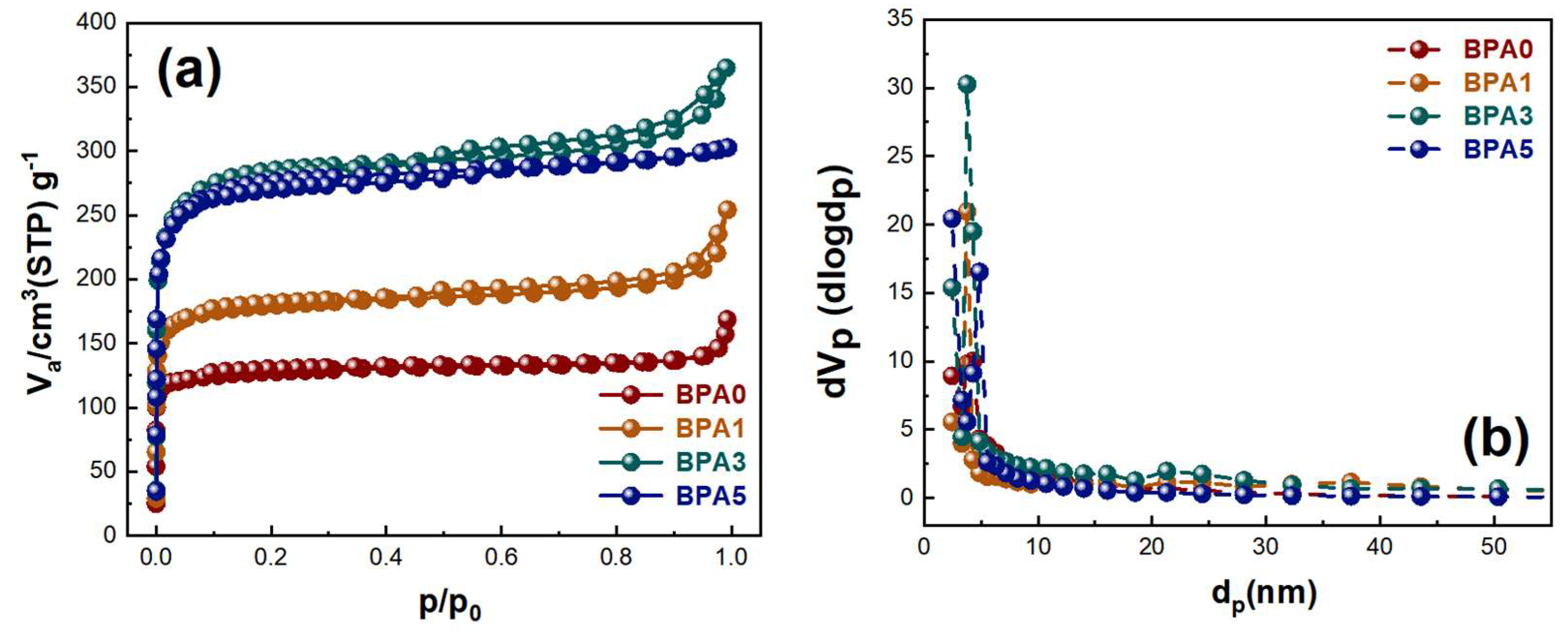
| Sample | Specific Surface Area [m2/g] | Total Pore Volume [cm3/g] | Mean Pore Diameter [nm] |
|---|---|---|---|
| BPA0 | 761 | 0.368 | 2.12 |
| BPA1 | 875 | 0.399 | 2.22 |
| BPA3 | 1053 | 0.498 | 3.65 |
| BPA5 | 924 | 0.435 | 2.57 |
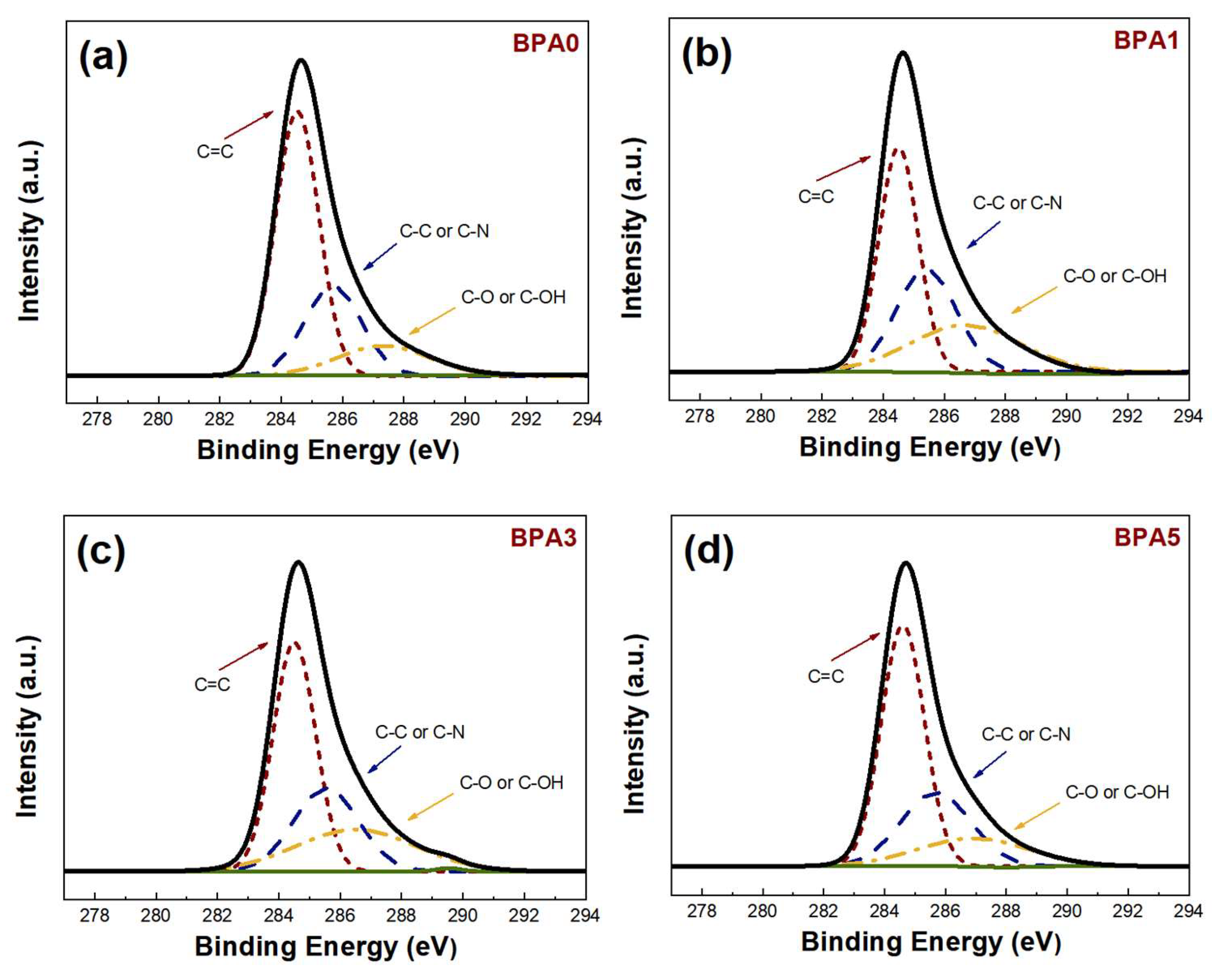
| Sample | Carbon (at. %) | Oxygen (at. %) | Nitrogen (at. %) |
|---|---|---|---|
| BPA0 | 82.29 | 11.04 | 6.67 |
| BPA1 | 81.81 | 12.64 | 5.55 |
| BPA3 | 78.97 | 16.37 | 4.66 |
| BPA5 | 79.98 | 13.99 | 6.03 |
Disclaimer/Publisher’s Note: The statements, opinions and data contained in all publications are solely those of the individual author(s) and contributor(s) and not of MDPI and/or the editor(s). MDPI and/or the editor(s) disclaim responsibility for any injury to people or property resulting from any ideas, methods, instructions or products referred to in the content. |
© 2024 by the authors. Licensee MDPI, Basel, Switzerland. This article is an open access article distributed under the terms and conditions of the Creative Commons Attribution (CC BY) license (https://creativecommons.org/licenses/by/4.0/).
Share and Cite
Park, J.-W.; Ju, Y.-W. Properties of Carbon Fibers as Supercapacitor Electrodes via Electrospinning Using a Blending Solution of Polyacrylonitrile and Bisphenol A. Energies 2024, 17, 1732. https://doi.org/10.3390/en17071732
Park J-W, Ju Y-W. Properties of Carbon Fibers as Supercapacitor Electrodes via Electrospinning Using a Blending Solution of Polyacrylonitrile and Bisphenol A. Energies. 2024; 17(7):1732. https://doi.org/10.3390/en17071732
Chicago/Turabian StylePark, Ji-Woo, and Young-Wan Ju. 2024. "Properties of Carbon Fibers as Supercapacitor Electrodes via Electrospinning Using a Blending Solution of Polyacrylonitrile and Bisphenol A" Energies 17, no. 7: 1732. https://doi.org/10.3390/en17071732