Abstract
This study presents an optimal design for a new rotary engine. Instantaneous shape functions were applied to the combustion chamber, and intake and exhaust ports were derived based on the rotor and housing design functions; then optimized design parameters were derived for a rotary engine. The three main parameters were shape distance, eccentric distance and rotor thickness. The design process for the optimized internal shape was subsequently defined considering target specifications for the rotary engine, and a prototype engine was designed and fabricated with a 336 cm3 intake volume. The compression pressure for the prototype engine was compared with the motoring test and calculated. These outcomes confirmed the new engine’s feasibility, and the derived geometric shape functions will be helpful to ensure optimal design for rotary engines using one- or three-dimensional computational fluid dynamics.
1. Introduction
The four-stroke reciprocating engine (RE) remains the most commonly employed prime mover. However, they have relatively complex engine structures, including a crank mechanism to convert reciprocating motion (pistons, etc.) into rotary motion, with various intake and exhaust valve mechanisms, and multiple cylinders are required for torque stability [1]. Although these engines are relatively commonly employed in small power systems, their efficiency decreases with miniaturization [2], and vibration and noise need significant improvement in mini combined heat and power (CHP) systems [3].
On the other hand, rotary engines (RTEs) convert cylinder pressure changes directly into rotational motion without requiring a crank mechanism and have simple intake and exhaust systems. Thus, RTEs have considerably fewer separate parts and are significantly smaller than REs for the same power output, which is advantageous for small-scale production. The Wankel engine (WE), developed in the early 1960s [4], is a representative RTE with practical advantages and disadvantages relative to REs [5,6]. Advantages include simple structure, low friction loss, a high power-to-weight ratio, favorable for high-speed rotation, and small vibration and torque fluctuations. Disadvantages include poor fuel economy and pollution performance, complex sealing and lubrication systems, and poor durability.
Disadvantages can be mostly attributed to the WE RTE structure: the WE mounts the combustion chamber on a rotating rotor, shaped like a thin square, and combustion occurs in a space moving in the flame propagation direction. Hence, engine seals must be located on the rotating inner rotor face, which makes lubrication difficult. Despite these disadvantages, they remain widely employed for some specialized applications.
LiquidPiston proposed the X engine (XE), an RTE type [7], with quite different geometry from the WE: the WE has two lobes in the housing, whereas the XE has two lobes in the rotor and three lobes in the housing. Both engines were designed using the Gerotor pump (GP) shape function [8,9]. LiquidPiston argued that the XE inherits WE advantages and improves WE disadvantages. The WE requires three seal types: side, apex, and corner seals, whereas XEs employ simplified sealing mechanisms to improve gas leakage [10]. The XE combustion chamber can also be installed in a fixed housing with relatively shape-free choice, and over-expansion strokes can be easily realized by appropriately positioning the intake and exhaust ports [11]. A 70-hp water-cooled diesel engine was initially devised to verify XE operation and basic principles [12], and a 70-cc air-cooled gasoline engine was subsequently applied to a small cart [13]. Recent research has continued to improve durability, heat transfer performance, and sealing performance aimed at developing emergency engines (range-extenders) for generators, small aircraft, and electric vehicles [14,15]. However, the X2 rotary engine, the successor to the first XE, suffered from a large surface area for the fuel-air mixture and a large engine wall, resulting in a large flameout volume, a major disadvantage for rotary engines, and was prone to emitting considerable amounts of unburned gas, constituting a further critical challenge.
The author’s research team has been developing a three-lobe Gerotor pump (GP3) RTE for several years, since the X2 engine could be suitable for mini-CHP applications with some further improvements. We have manufactured and investigated several prototype engines and conducted various one- and three-dimensional (1D and 3D, respectively) computational fluid dynamics analyses. Design tool requirements can systematically modify design factors over time, allowing comprehensive optimization studies, as reported here. Many previous studies have considered GP design parameters, and WE design parameters remain under intense study in South Korea and abroad. However, few studies have considered design optimization for new RTEs in South Korea and abroad.
This present study considered the GP3 optimal design based on the X2. Design variables included rotor and housing structure and operational mechanisms, engine shape, relationships between combustion chamber volume and surface area, and effective port area. In particular, we carefully investigated contact angle, critical to engine sealing, and derived a design variable guide incorporating empirical relationships between intake optimization and effective area. The results of this study are expected to be very useful for the design and development of the GP3 rotary engine. We used 1D and 3D CFD analysis for the GP3 RTE to determine the engine stroke and flow characteristics to investigate the validity of the associated design factors.
2. GP3 Engine Structure and Operation
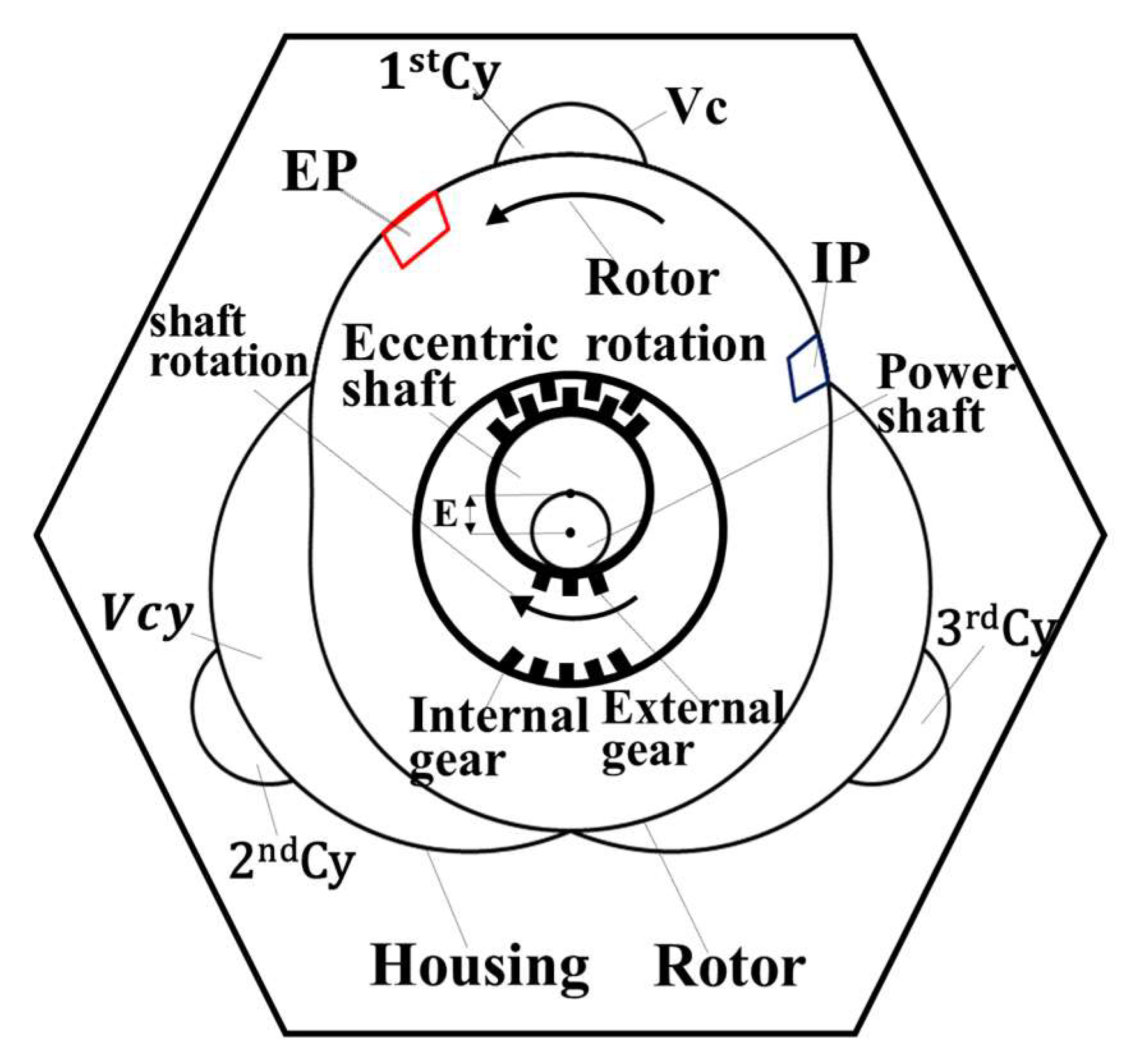
Figure 1 shows a cross-sectional view of the GP3 RTE core, showing the eccentric power shaft, rotor, and housing arranged in sequence from center to radial direction. The rotor rotates counterclockwise as the eccentric shaft rotates clockwise, always touching the three housing apexes, resulting in an eccentric rotation. The external and internal gears at the power shaft and rotor sides, respectively, were designed such that the rotor rotates once while the power shaft rotates twice. The rotor corresponds to the RE piston, with geometry based on an epitrochoidal function with two lobes. The housing inner circle is shared by three lobes, spaced 120° apart, with shapes determined by the eccentrically rotating rotor’s outermost trajectory. The three cavities, along with clearance volumes between the rotor and housing, correspond to the RE cylinder volume, Vcy. Hence, a single GP3 RTE effectively incorporates three cylinders, each with a combustion chamber, Vc, hollowed at the top central region for each cylinder.
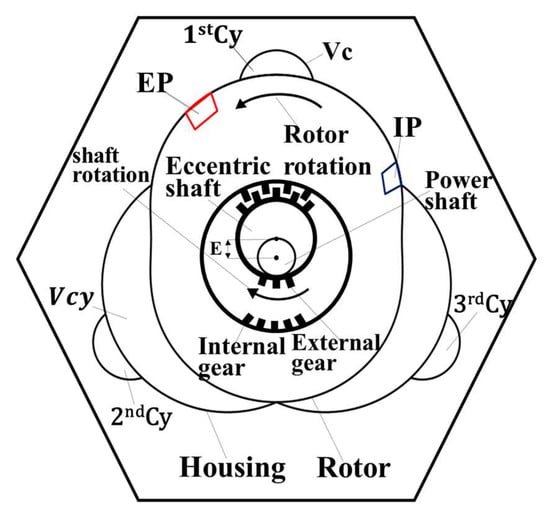
Figure 1.
GP3 engine core configuration.
A major advantage of this GP3 RTE engine is that Vc can be installed in a fixed housing, whereas the WE, geometry design requires that Vc be installed on the outer circumference of the rotating inner rotor, which imposes many constraints on the Vc geometry. On the other hand, the proposed GP3 has Vc installed in a fixed housing; hence, the shape design is relatively free.
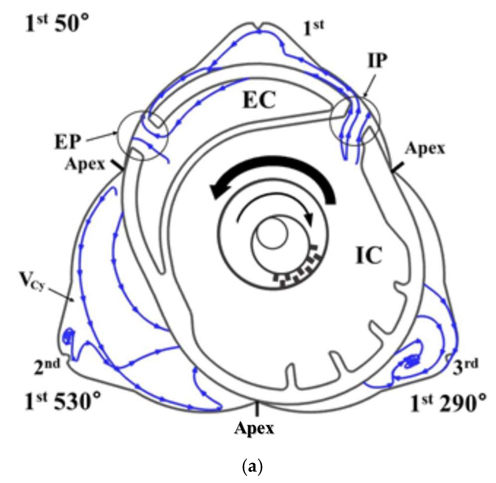
Figure 2 shows the intake (IP) and exhaust (EP) port timing and stroke range with respect to the power shaft rotation angle (SRA). The proposed GP3 characteristics differ significantly from the REs and provide insight into the GP3 operating principles. Figure 2a shows a cross-sectional view of the first prototype GP3 rotor-housing. The internal space is always divided into three apexes, creating three cylinder volumes (Vcy), since each cylinder (Cy) has a machined combustion chamber (Vc). The GP3 engine rotor rotates counterclockwise once as the eccentric power shaft rotates clockwise twice. The cylinder order (1–3) is determined by the order of counterclockwise rotor rotation (see Figure 2), and the SRA is based on the rotor being at TDC (0°) for the 1st cylinder. Figure 2a shows the case for SRA = 50°, with the first Cy in intake mode. Hence, considering the phase difference, the third (290°) cylinder is in the compression process, and the second cylinder is at the end of expansion (530°).
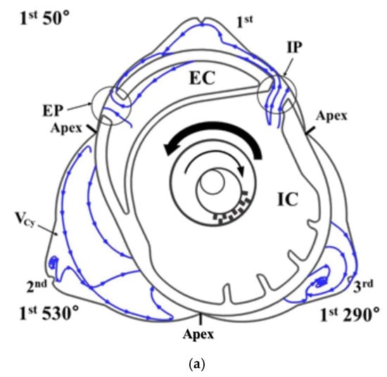

Figure 2.
Intake(IP) and Exhaust(EP) timing and stroke sharing for the proposed GP3 engine. (a) Proposed GP3 stroke processes; (b) Port open timing and four strokes.
Figure 2b shows the EP/IP open period and stroke period for the 1st and subsequent Cy during one cycle (SRA = 720°, 1 rotor rotation). Thus, the port open period for the proposed GP3 engine is 1/3 of the rotor and the port width, i.e., 240° + at SRA. The rotation angle corresponding to the port width is = = 20° for the engines in this experiment. The IP/EP openings for the engines in Figure 2b, 1st Cy = 700° to 240° (240° + ) and 540° to 80° (240° + ), respectively, with overlap = 700° to 80° (60° + +). Therefore, the net open IP/EP period = 2/3 of a cycle minus the net overlap (i.e., excluding + , and the compression/expansion period is used to distribute the remaining period. Thus, the proposed GP3 engine has a net open period of {(480° + + (60° + + )} = 420°, with 120° compression and 180° expansion periods, respectively.
3. Design Parameters and Specifications for the Proposed Rotary Engines
3.1. Rotor and Housing Design Parameters
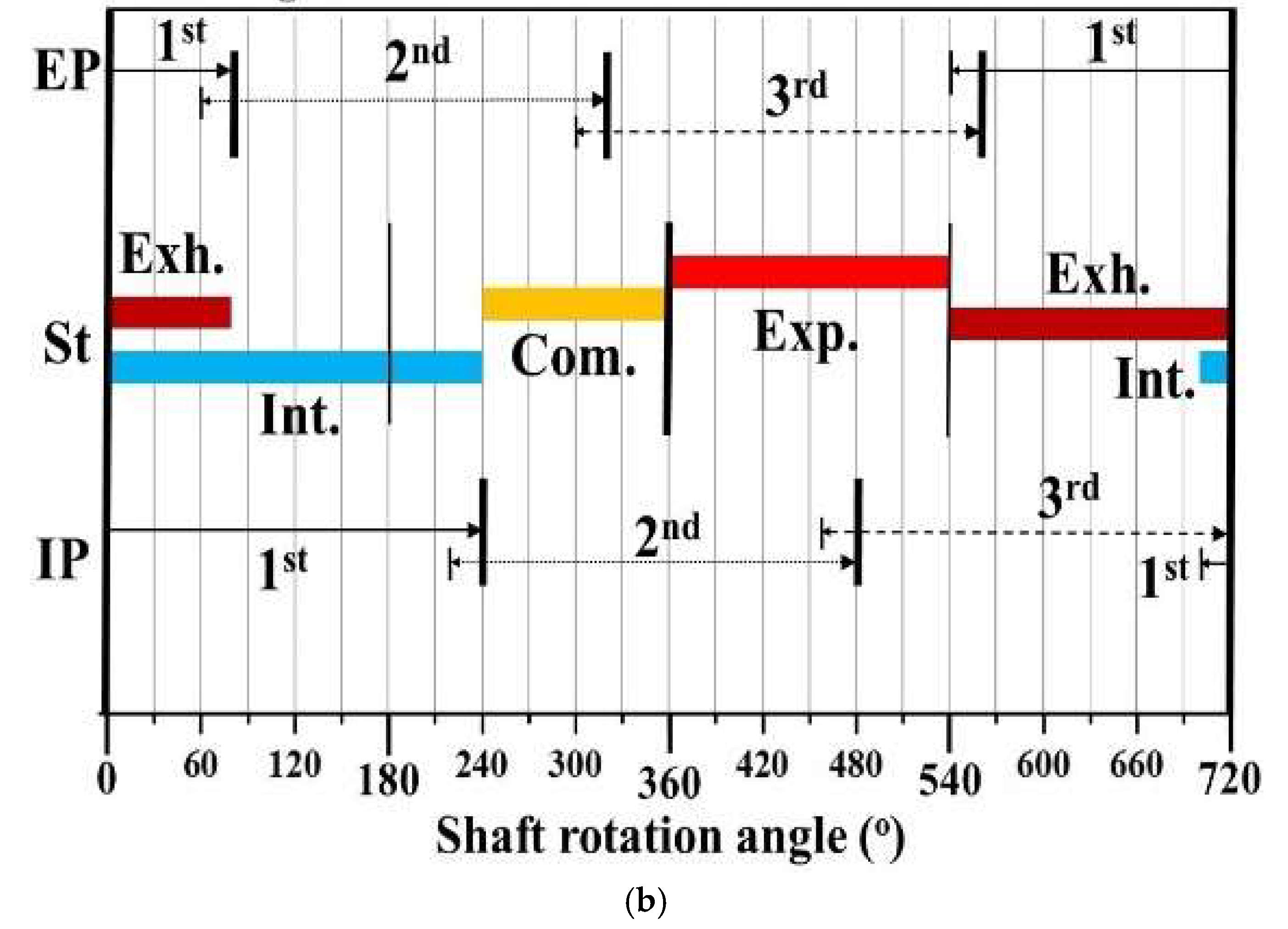
Figure 3 shows the external geometry of the rotor using trochoidal theory. A trochoid is a trajectory followed by an arbitrary point inside a moving circle as it rotates over an arbitrary geometry. These trajectories are usually categorized by prefixes, such as hypo when the rolling circle is rotated inside a fixed circle and epi when the rolling circle is rotated outside the base circle. Therefore, the proposed GP3 engine has an epitrochoid rotor [9].
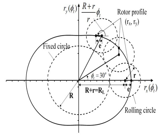
Figure 3.
Rotor external shape from trochoid theory.
Equation (1) shows the x and y coordinates for an arbitrary point on the moving circle when the moving circle is rotated counterclockwise around the x axis (see Figure 4) can be expressed as
respectively. Since the moving circle rotates once around the outside of the fixed circle, the moving circle is rotated by RL = R + r and its ratio to r, Z = , because the moving circle rotates and revolves around the stationary source. Thus, the number of lobes on the rotor = Z − 1. The number of lobes for the QP3 rotor = 2, and hence Z = 3. Therefore, design parameters for the rotor are: RL (=R + r), eccentric length (e), and rotor thickness (H). where R is the stationary circle radius, r is the moving circle radius, e is the distance between any point on the moving circle and the center, and is the moving circle angle.

Figure 4.
Proposed GP3 rotor rotation with respect to the power shaft angle.
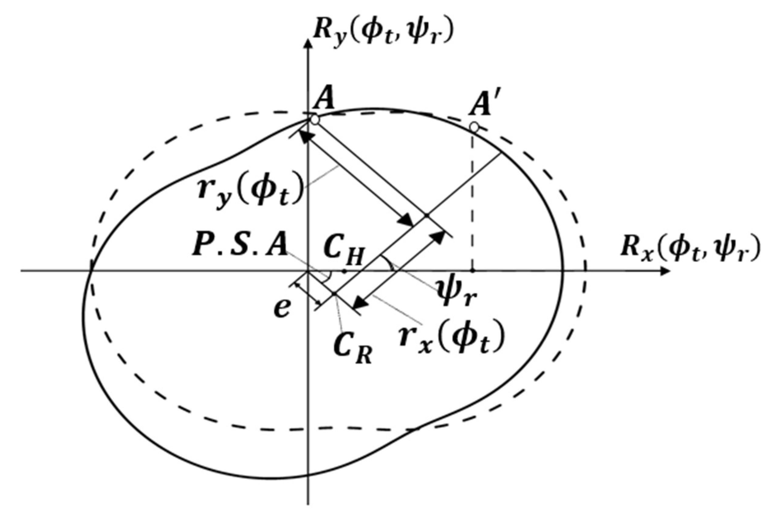
Figure 4 describes the GP3 rotor’s rotational motion. The rotor is eccentric by e and rotates clockwise around CH by power shaft angle (PSA). At CR, the rotor has rotated counterclockwise by the same amount, hence the coordinates move from A’ to A, and PSA doubles. Therefore, WP3 rotor rotation coordinates can be expressed as
where is the rotor rotation angle, i.e., the moving source rotation angle.
Internal housing shape is determined by the eccentrically rotating rotor’s outermost angle trajectory. Although the rotor equation can be used to determine internal housing shape, it has the disadvantage to require three equations, one for each housing lobe. Therefore, the internal housing shape was calculated using the Lagrange multiplier method [16].
where is the housing geometry angle (0°–360°).
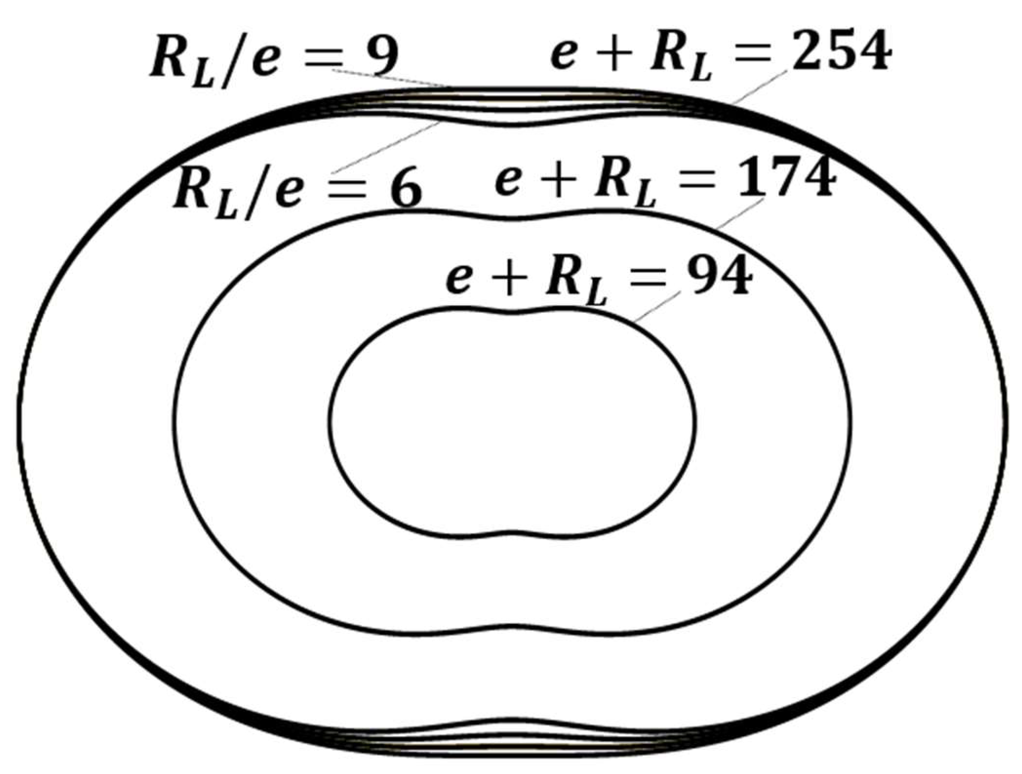
Figure 5 shows the shape and size evolution for the inner rotor using the GP3 design parameters defined earlier, i.e., rotor eccentric length e and shape distance RL = R + r. Rotor size = e + RL was fixed while the ratio k = RL/e, was varied. Inner rotor size also remains constant since the rotor size was fixed. However, the rotor shape becomes more elliptical as k increases, due to the rotor size (e + RL) changing, while retaining the eccentric length and shape distance ratio. Thus, the rotor shape remains the same, only the size increases.
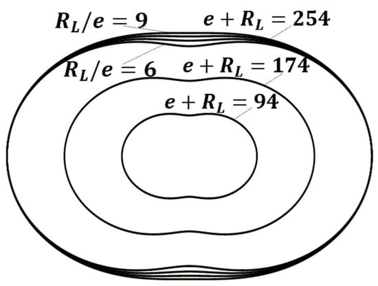
Figure 5.
Rotor geometry according to design parameters.
3.2. Optimal Relationship between Combustion Chamber Volume and Surface Area
This section calculates and evaluates the engine specifications for each design variable to determine the optimal parameters for the GP3 engine. Figure 6 shows the process to calculate the GP3 engine volume and surface area with respect to the rotor rotation angle (). The GP3 engine volume can be calculated by integrating the width of the micro fan.

Figure 6.
Calculation method for GP3 volume and surface with respect to rotor angle.
The GP3 engine volume is then the difference between the housing and rotor volumes
where H is the engine thickness; Hx and Hy, and Rx and Ry are x and y coordinates for the housing and rotor, respectively.
The surface area of the top and bottom is calculated by dividing the volume by the height, and the sides are calculated by multiplying the length of the arc of the smile by the height. Therefore, the GP3 engine surface area is the total surface area from the top and bottom housings, the rotor sides, and the combustion chamber,
where V() is the engine stroke volume at , and Ac is the combustion chamber surface area.
3.3. Contact Angle
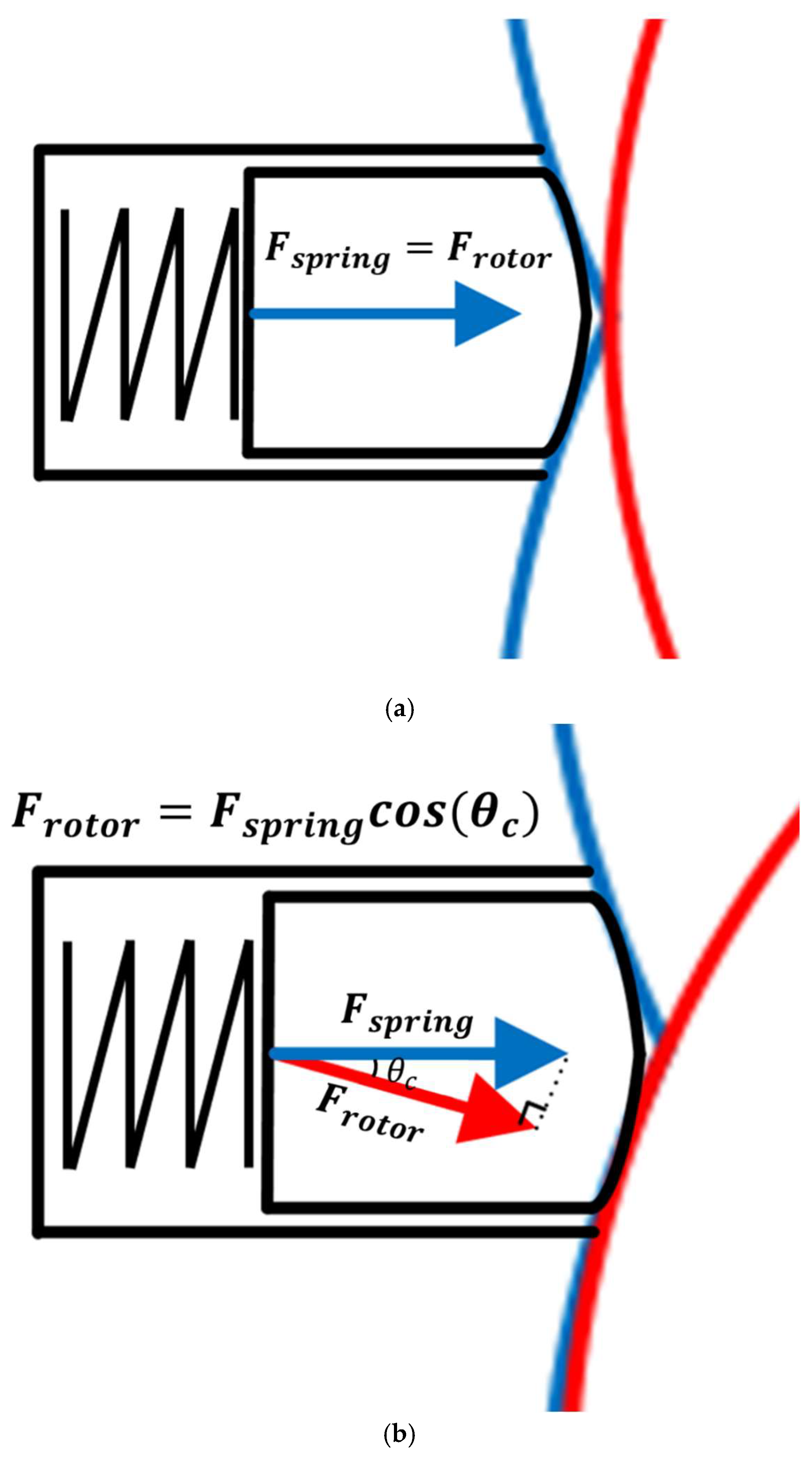
Figure 7 shows the apex seal with respect to the contact angle. The apex seal utilizes the spring tension to prevent mixed gases from entering between the housing lobes. The contact angle () between the apex seal and the rotor face can be expressed as
where is the contact angle; Rx and Ry are the eccentric rotor x and y coordinates, respectively; and is the seal position angle (180° for the case in Figure 7a).

Figure 7.
Apex seal for different contact angles. (a) Contact angle = 0°; (b) Contact angle = 30° (red line: rotor, blue line: housing).
For example, when the rotor is in the middle position of the apex seal (Figure 7a), the rotor normal angle = 180°. The contact angle is the rotor normal minus the seal position angle (180°); hence, the contact angle = 0°, i.e., the force acting on the rotor face = spring tension. When the rotor is not in the middle of the apex seal (Figure 7b), the rotor normal = 210°. The contact angle is the rotor normal minus the seal position angle (180°), the contact angle = 30°, hence the seal force acting on the rotor is reduced by the dispersion force. Therefore, a larger contact angle in the GP3 engine implies a smaller force acting on the rotor surface, which is unfavorable for sealing. The contact angle is an important parameter for sealing (discussed in more detail in Section 4).
3.4. Port Effective Area and Change
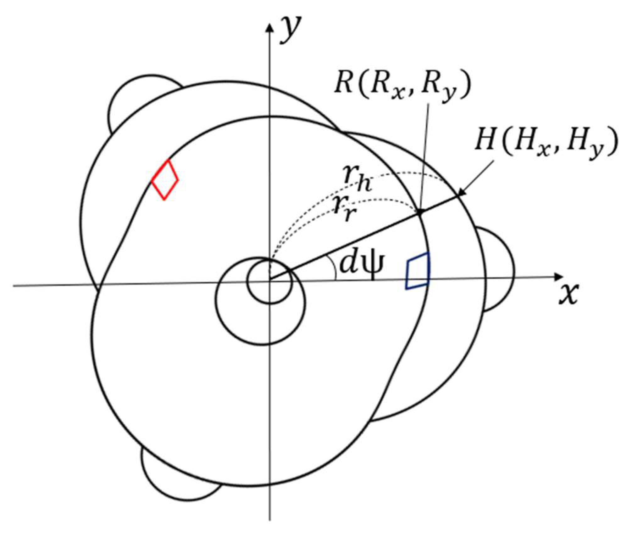
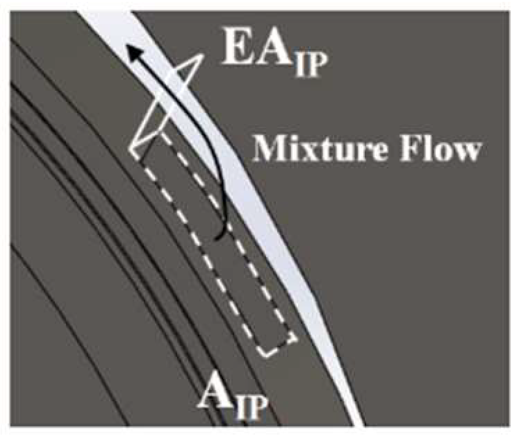
The varying effective area (EA) is a unique feature of the GP3 engine and is an important factor for IP/EP positioning. It also has a significant effect on fresh air intake, EGR rate, and compression/expansion period. Figure 8 shows the mixture passing through the effective area at the intake port; hence, EA corresponds to the actual intake and exhaust flow path and can be expressed as
where the port approaches the housing, and is the angle that forms the clearance gap,
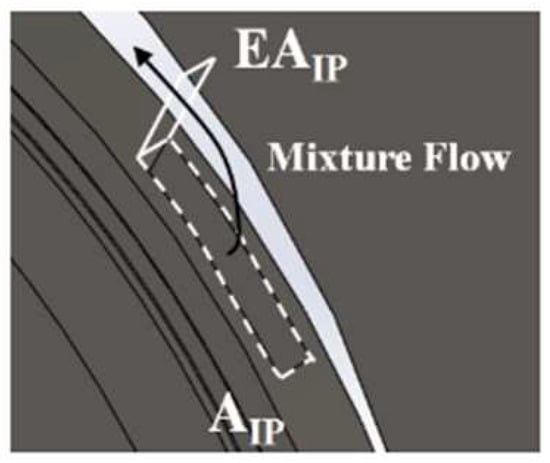
Figure 8.
Effective area (EA) concept for the proposed GP3 engine (arrow: mixture direction, dashed line: port area).
Figure 9 shows the geometric open area (A) variation for the IP and EP and EA corresponding to the actual flow paths with respect to the SRA, as defined in (8), corresponding to the effective intake and exhaust flow area. The figure shows 1st Cy, where the SRA negative angle represents bTDC. This change in EA is repeated in the next Cy with a 240° phase difference.
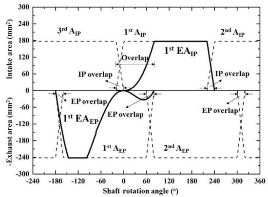
Figure 9.
Effective flow areas for intake and exhaust ports.
There is a considerable difference between A and EA at around 90° before and after TDC (0°), i.e., EAEP decreases sharply from −90°, closing temporarily at TDC (0°), then opening slightly again. The reopening (0° to 80°) is the intake period, so exhaust gas is re-aspirated (EGR) through the EP. The EAIP is also almost zero before TDC (0°), then slowly increases to equal with AIP at approximately 90°. The EP/IP overlap reduces, and the EAEP reopens after TDC (0°). Therefore, the possibility of EGR through the EP is also blocked. This characteristic EA change with IP/EP position is unique to the proposed GP3 engine and is an important factor affecting fresh air intake, EGR rate, and compression/expansion period.
4. Results and Discussion
4.1. Optimal Geometry Design for a Small GP3 Engine
In this section, we discuss the judgment criteria (eccentric length, contact angle, surface area/volume) changes following the GP3 design parameters described above and present the optimal design. Table 1 shows the GP3 specifications, and Table 2 shows the design parameters and final values. The GP3 engine is naturally aspirated, fueled by city gas, and has three cylinders (lobes). The combustion chamber volume for each cylinder = 11 cc, and the stroke volume = 112 cc; hence, the compression ratio = 11 and the total stroke volume = 336 cc. Engine design parameters e, RL, and H, as discussed in Section 3.1. For convenience, we define k = RL/e, and H as the design variables since the stroke volume = 112 cc and the other design variable values can be determined from these two design variables.

Table 1.
GP3 engine specifications.
Table 2.
GP3 engine design parameters.
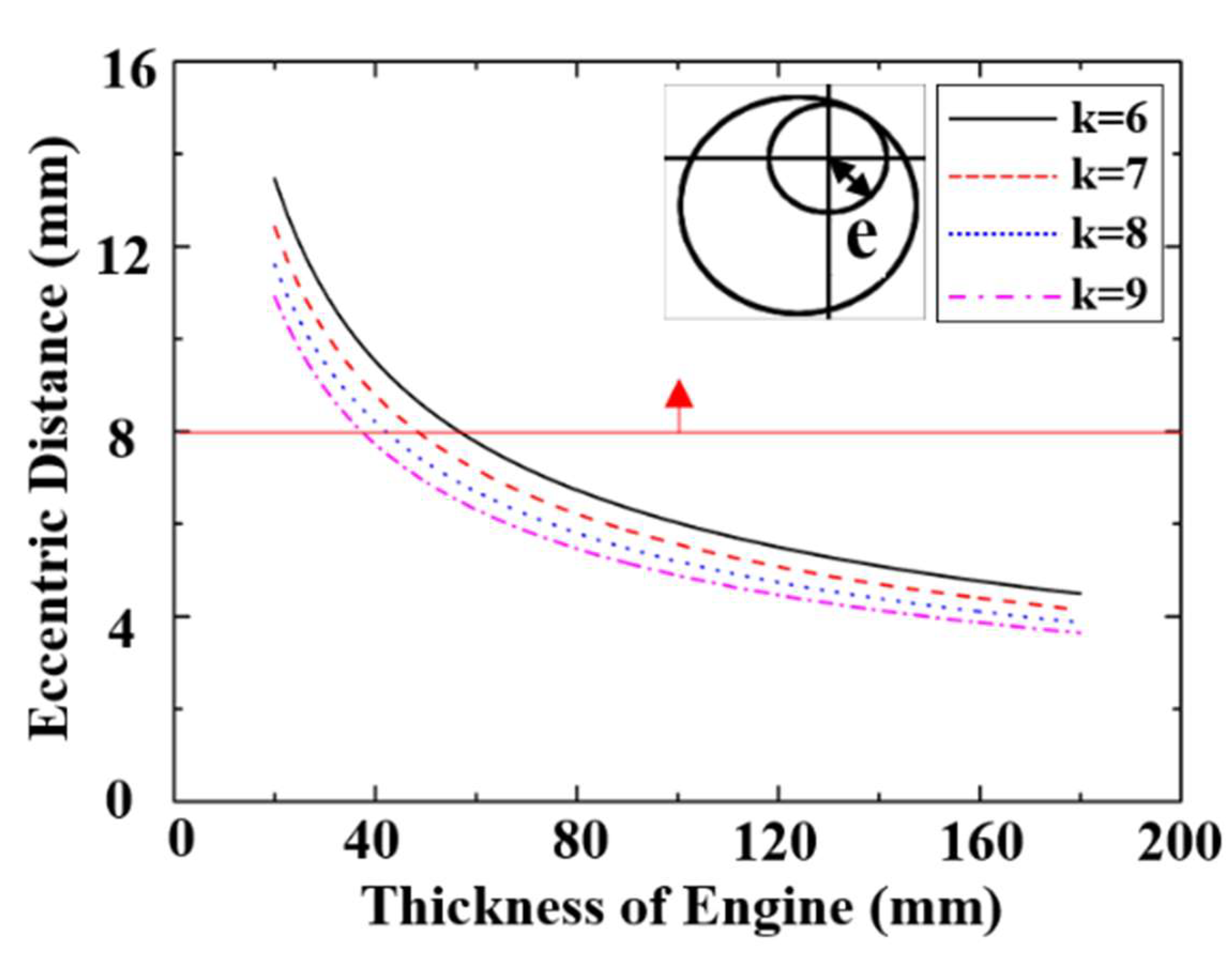
Figure 10 shows the eccentric length with respect to the GP3 design parameters. The power shaft (eccentric shaft) must have sufficient diameter to transmit the power generated by the engine without breaking, but the eccentric length is proportional to the power shaft size and is the most important criterion for engine durability. The eccentric length variance with the design variables at the same delivery volume confirms that the eccentric length decreases as H increases, due to reducing the rotor top surface width, whereas eccentric length increases as k increases. The eccentric length also decreases significantly as thickness increases and decreases slightly as k increases. Therefore, setting engine thickness ≤ 40 mm is more effective in increasing the eccentric length than using k to satisfy the minimum requirement (red line).
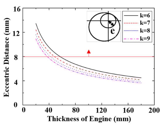
Figure 10.
GP3 engine eccentric length with respect to design parameters (8 mm is the minimum length for durability).
Figure 11 shows the contact angle with respect to GP3 design parameters. As discussed in Section 3.2, the contact angle is an important value for relative sealing degree, and smaller contact angles imply a smaller differential force magnitude, which is favorable for sealing. The contact angle reduces as k increases, regardless of engine thickness, because the contact angle decreases as the rotor shape changes from peanut to elliptical as k increases (see Figure 5). Therefore, optimal k ≥ 7 to satisfy the minimum contact angle requirement ≤ 25 (Figure 11, red line), where momentum magnitude < 10%.
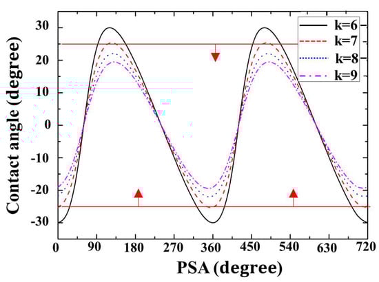
Figure 11.
GP3 contact angle with respect to power shaft angle (PSA).
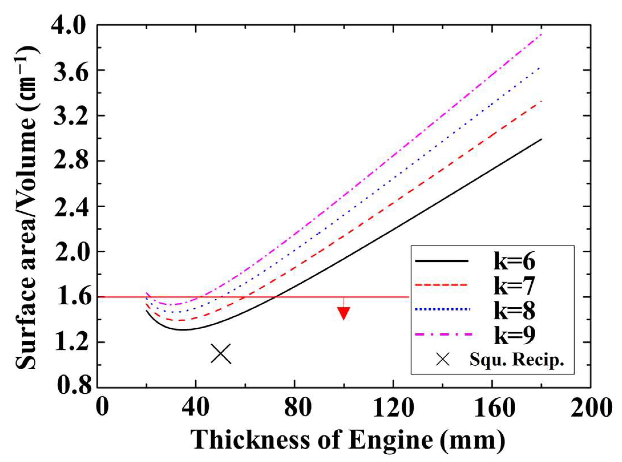
Figure 12 shows the GP3 surface area/volume ratio with respect to the design parameters, with the surface area fixed at the maximum. The GP3 surface area should be designed to minimize heat loss and ensure smooth combustion. The surface area/volume changes are shown with respect to design variables at the same stroke volume. Surface area decreases as thickness increases, reaching the minimum at approximately 30 mm and then increasing again; it also increases with increasing k. The changes as engine thickness increases can be explained by considering the top and bottom engine widths that constitute the cross-sectional area and changes in the engine side width. The top and bottom GP3 engine areas have the same stroke volume for small H (≤30 mm), hence the top and bottom area reduction is larger than the side area increase. On the other hand, the top and bottom rotor area reduction is smaller than the side area increase for larger H (≥30 mm). Therefore, the total surface area of the engine tends to decrease and then increase as motor thickness increases.
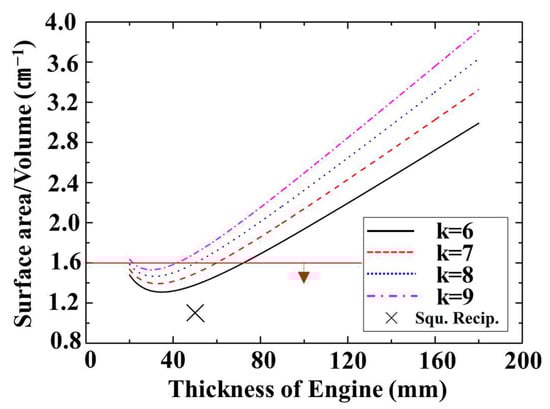
Figure 12.
Surface area to Volume ratio for the proposed GP3 engine design parameters.
The surface area tends to increase as the k increases. Hence, the rotor shape becomes more elliptical as the surface area increases for the same stroke (see Figure 5). The minimum requirement is ≤1.4 × surface area/volume ratio for a square RE with the same stroke volume. Therefore, the thickness of the GP3 engine should be approximately 30 mm and should be small k to minimize the surface area. We selected optimal specifications for the GP3 engine based on the design parameters described above. The judgement criteria priority was set as: eccentric length related to durability, contact angle related to sealing, and surface area/volume related to heat loss. The optimal design parameter values for the GP3 engine were influenced more by thickness than by k, considering eccentric length and surface area/volume. Therefore, the thickness was set at approximately 30 mm to secure eccentric length, and surface area/volume were simultaneously close to minimum. Although a small k is advantageous, we set k ≈ 8 to satisfy all the criteria.
4.2. Prototype Motoring Performance
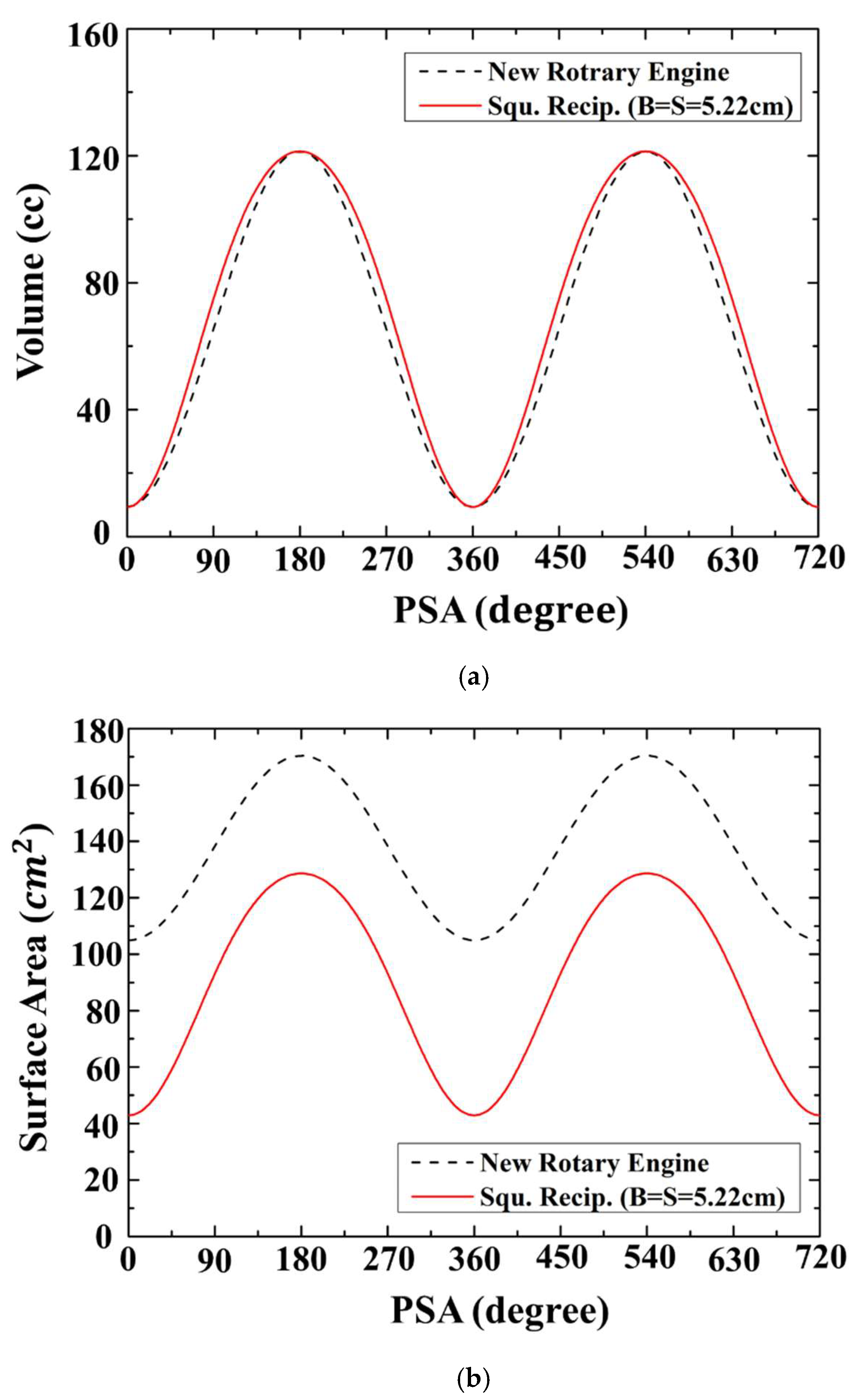
Figure 13 compares the volume and surface area of the square RE engine and the GP3 using the optimal parameters (Section 4.1) with respect to the power shaft rotation angle. Figure 13a,b shows that the stroke volume is very similar between the two engines, whereas the GP3 surface area is 1.3 and up to 2.4 times larger than the surface area of the RE. Therefore, the GP3 engine has a large heat loss due to the increase in average surface area despite the optimized design.
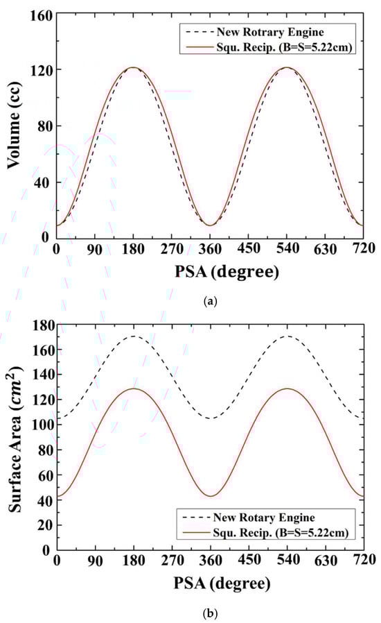
Figure 13.
Proposed optimized GP3 engine and typical reciprocating engine parameters. (a) Volume; (b) Surface Area.
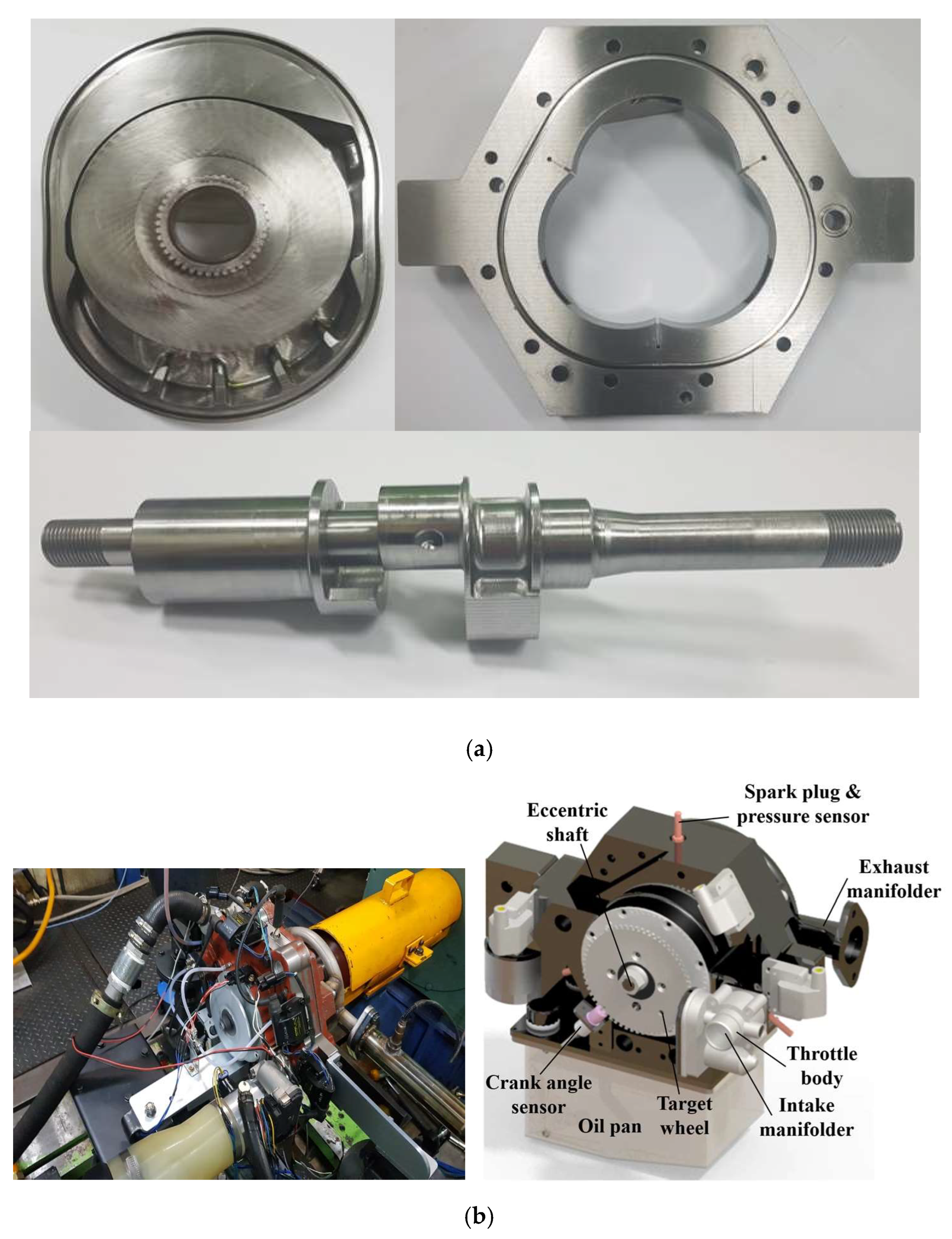
Figure 14 shows the actual prototype GP3 engine. Figure 14a shows the machined core engine components (rotor, housing, and power shaft). The rotor has an intake/exhaust space, the housing has an apex seal for the tap chamber and a cooling water channel, and the power shaft has a tab for the target wheel. Figure 14b left panel shows the prototype engine installed on a dynamometer to verify performance, and the right panel shows an air intake line with a throttle installed. A coolant line (left side of the figure), and an oil pan were installed for the engine cooling and lubrication, respectively. Sensors comprised crank angle and spark plug (pressure) sensors, and a thermocouple.
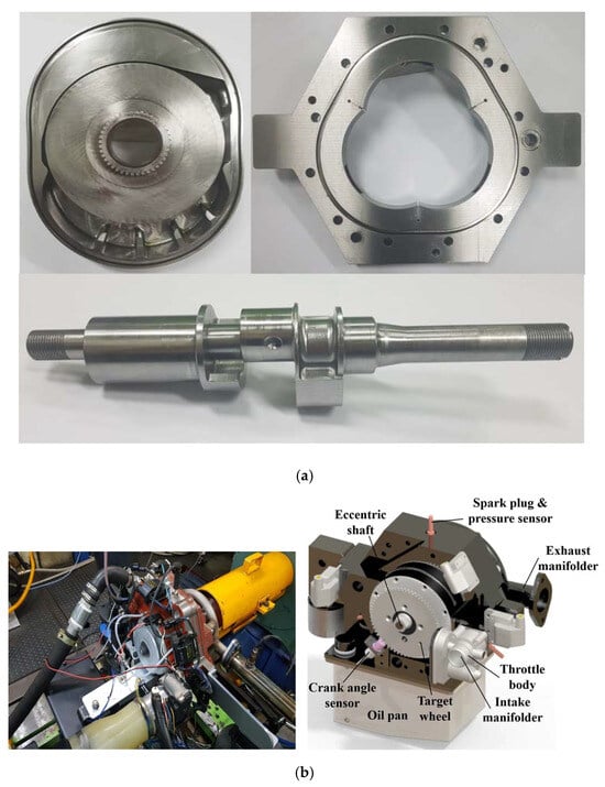
Figure 14.
Optimized GP3 prototype engine. (a) GP3 prototype engine core parts; (b) GP3 experimental setup.
Figure 15 shows the P-V diagram of the GP3 engine from motoring tests. We found a typical over-expansion four-stroke cycle when we increased to 3000 rpm and a maximum compression pressure ≈ 13.5 bar, somewhat lower than the theoretical calculation from the isentropic compression process (17 bar). Therefore, further research is required to improve intake timing and sealing.
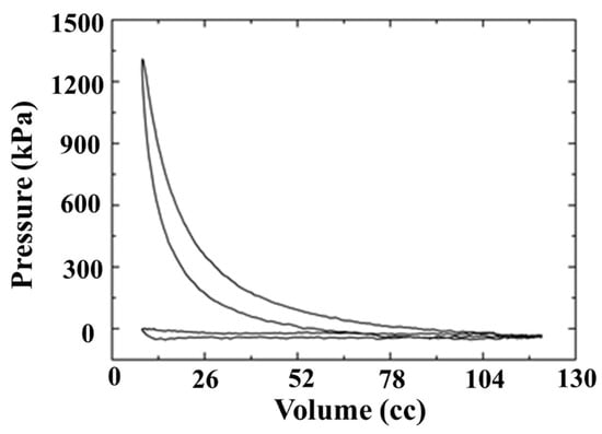
Figure 15.
Prototype GP3 engine Pressure-Volume curves from motoring tests at 3000 rpm.
5. Conclusions
The results of this study into the optimal parameters for a GP3 rotary engine can be summarized as follows:
- The proposed GP3 engine design sequence comprises determining rotor and housing shape functions, deriving optimal relationships between combustion chamber volume and surface area, optimizing contact angle, and finally optimizing inlet and exhaust port effective area. We identified the main design parameters to be eccentric length (e), rotor length (RL), and engine thickness (H), and optimization of these three design parameters determines the engine shape.
- Criteria for designing the optimal GP3 shape are the eccentric shaft radius, which determines high-speed rotating power shaft durability; the contact angle, which determines the engine sealing ability; and the surface area to volume ratio, which indicates the heat loss level. A new GP3 rotary engine was designed and manufactured based on these optimal parameters.
- Optimizing engine thickness (H) and ratio of rotor length and eccentric length (k) revealed that reducing H and increasing k were favorable for optimal design, and this principle was applied to actual engine production.
- We calculated optimal k = 8 and H = 30 mm and confirmed that all the criteria for the optimal shape design could be satisfied.
- The calculated effective area for the proposed GP3 engine was applied for flow analysis and accurate intake and exhaust flow analysis.
- Motoring tests with core parts and auxiliary devices designed from these study outcomes confirmed that the maximum compression pressure at 3000 rpm was maintained at 13.5 bar and operated normally.
Author Contributions
Conceptualization, T.-J.P.; formal analysis, J.-H.Y.; data curation, T.-J.P.; writing original draft preparation, T.-J.P.; writing review and editing, Y.-J.K.; supervision, C.-E.L.; project administration, C.-E.L. All authors have read and agreed to the published version of the manuscript.
Funding
This research was funded by Inha University Research fund 2021.
Data Availability Statement
Data are contained within the article.
Conflicts of Interest
The authors declare no conflict of interest.
Nomenclature
| A | area |
| EA | effective area |
| EAIP | effective area intake port |
| EAEP | effective area exhaust port |
| BDC | bottom dead center |
| CR | compression ratio |
| Cy | cylinder |
| EC | exhaust chamber |
| EP | exhaust port |
| EW | exhaust window |
| GP3 | Gerotor pump with three robes |
| IC | intake chamber |
| IW | intake window |
| IP | intake port |
| P | pressure |
| PSA | power shaft angle |
| RE | reciprocating engine |
| RTE | rotary engine |
| SRA | shaft rotation angle |
| ST | surge tank |
| St | stroke |
| TDC | top dead center |
| Vc | Combustion chamber Volume |
| Vcy | Cylinder Volume |
| WE | Wankel engine |
| Subscripts | |
| E | effective |
| C | clearance |
| D | displacement |
References
- Heywood, J.B. Internal Combustion Engine Fundamentals; McGraw-Hill: New York, NY, USA, 1988. [Google Scholar]
- Engine Specifications. HONDA GXV120. Available online: https://www.engine-specs.net/honda/gxv120.html (accessed on 1 March 2021).
- Mikalsen, R. Internal combustion and reciprocating engine systems for small and micro combined heat and power (CHP) applications, small and micro combined heat and power (CHP) systems: Advanced design, performance, materials and applications. In Small and Micro Combined Heat and Power (CHP) Systems; Elsevier: Amsterdam, The Netherlands, 2011; pp. 125–146. [Google Scholar] [CrossRef]
- Wankel, F. Rotary Internal Combustion Engine. U.S. Patent US2,988,065 A, 1958. [Google Scholar]
- Wikipedia. Wankel Engine. Available online: https://en.wikipedia.org/wiki/Wankel_engine (accessed on 1 March 2021).
- Bartrand, T.A.; Willis, E.A. Rotary engine performance limits predicted by a zero-dimensional model 920301. J. Engines 1992, 101, 442–458. [Google Scholar]
- Shkolnik, N.; Shkolnik, A.C. Cycloid Rotor Engine. U.S. Patent US2012-0294747A1, 17 July 2012. [Google Scholar]
- Colbourne, J.R. The geometry of trochoid envelopes and their application in rotary pumps. Mech. Mach. Theory 1974, 9, 421–435. [Google Scholar] [CrossRef]
- Gamez-Montero, P.J.; Codina, E. Flow characteristics of a trochoidal-gear pump using bond graphs and experimental measurement. Part 1. Proc. Inst. Mech. Eng. Part I J. Syst. Control. Eng. 2007, 221, 331–346. [Google Scholar] [CrossRef]
- Leboeuf, M.; Dufault, J.F.; Nickerson, M.; Becker, K.; Kopache, A.; Shkolnik, N.; Shkolnik, A.; Picard, M. Performance of a Low-Blowby Sealing System for a High Efficiency Rotary Engine. In SAE Technical Paper; SAE International: Warrendale, PA, USA, 2018; pp. 1–10. [Google Scholar]
- Shkolnik, N.; Shkolnik, A. Rotary High Efficiency Hybrid Cycle Engine. In SAE Technical Paper; SAE International: Warrendale, PA, USA, 2008. [Google Scholar]
- Shkolnik, A.; Littera, D.; Nickerson, M.; Shkolnik, N.; Cho, K. Development of a Small Rotary SI/CI Combustion Engine. In SAE Technical Paper; SAE International: Warrendale, PA, USA, 2014. [Google Scholar]
- Littera, D.; Nickerson, M.; Kopache, A.; Machamada, G.; Sun, C.; Schramm, A.; Medeiros, N.; Becker, K.; Shkolnik, N.; Shkolnik, A. Development of the XMv3 high efficiency cycloidal engine. In SAE Technical Paper; SAE International: Warrendale, PA, USA, 2015. [Google Scholar]
- Shkolnik, A.; Shkolnik, N.; Scarcella, J.; Nickerson, M.; Kopache, A.; Becker, K.; Bergin, M.; Spitulnik, A.; Equiluz, R.; Fagan, R.; et al. Compact, Lightweight, high efficiency rotary engine for generator, APU, and range-extended electric vehicles. In Proceedings of the NDIA Ground Vehicle Systems Engineering and Technology Symposium, Novi, MI, USA, 7–9 August 2018; pp. 16–18. [Google Scholar]
- Costa, T.J.; Nickerson, M.; Littera, D.; Martins, J.; Shkolnik, A.; Shkolnik, N.; Brito, F. Measurement and prediction of heat transfer losses on the xmv3 rotary engine. SAE Int. J. Engines 2016, 9, 2368–2380. [Google Scholar] [CrossRef]
- Shung, J.B.; Pennock, G.R. Geometry for trochoidal-type machines with conjugate envelopes. Mech. Mach. Theory 1994, 29, 25–42. [Google Scholar] [CrossRef]


Disclaimer/Publisher’s Note: The statements, opinions and data contained in all publications are solely those of the individual author(s) and contributor(s) and not of MDPI and/or the editor(s). MDPI and/or the editor(s) disclaim responsibility for any injury to people or property resulting from any ideas, methods, instructions or products referred to in the content. |
© 2024 by the authors. Licensee MDPI, Basel, Switzerland. This article is an open access article distributed under the terms and conditions of the Creative Commons Attribution (CC BY) license (https://creativecommons.org/licenses/by/4.0/).