
Anisotropic Mechanical Behaviors of Shale Rock and Their Relation to Hydraulic Fracturing in a Shale Reservoir: A Review


Abstract
1. Introduction
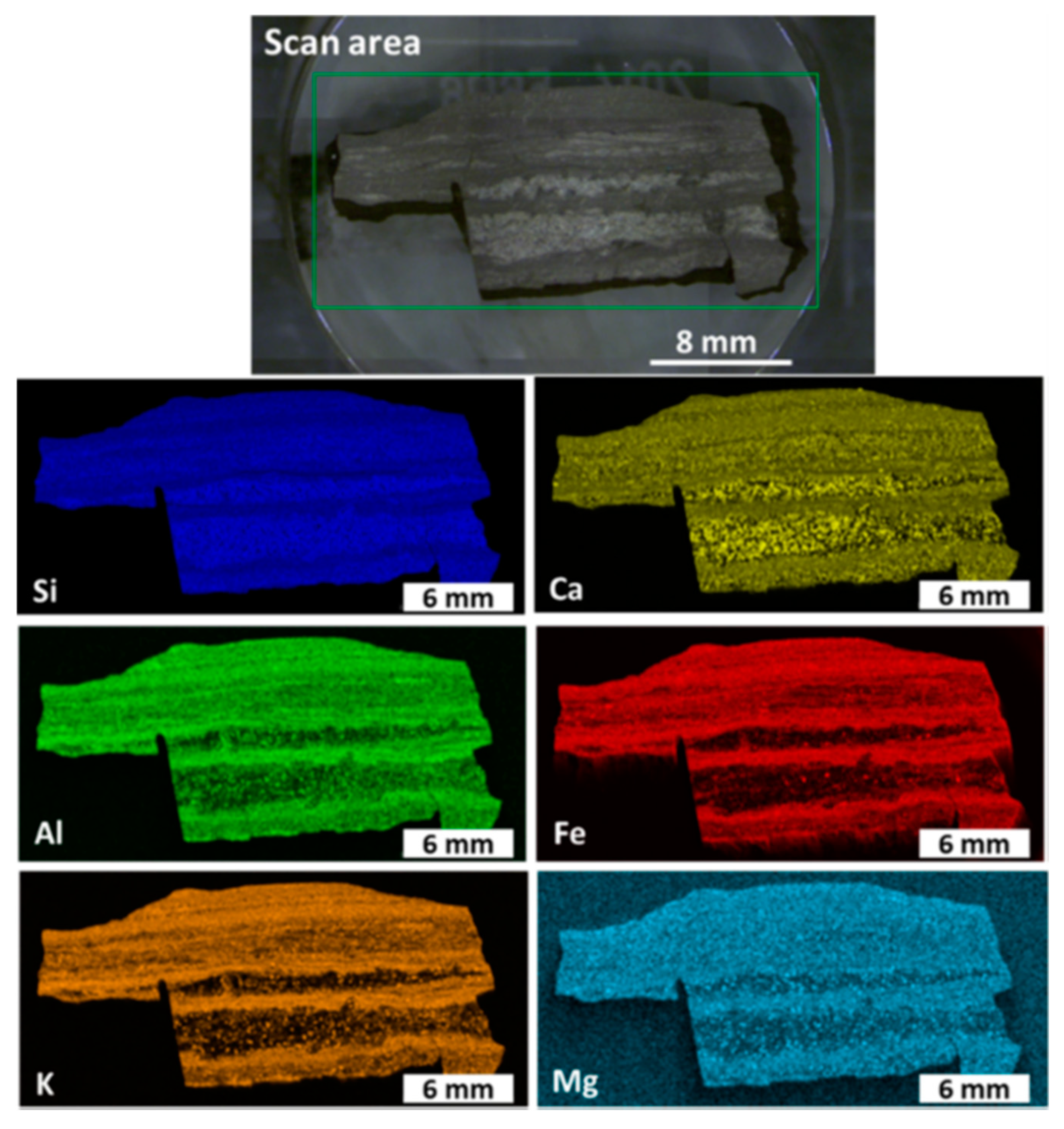
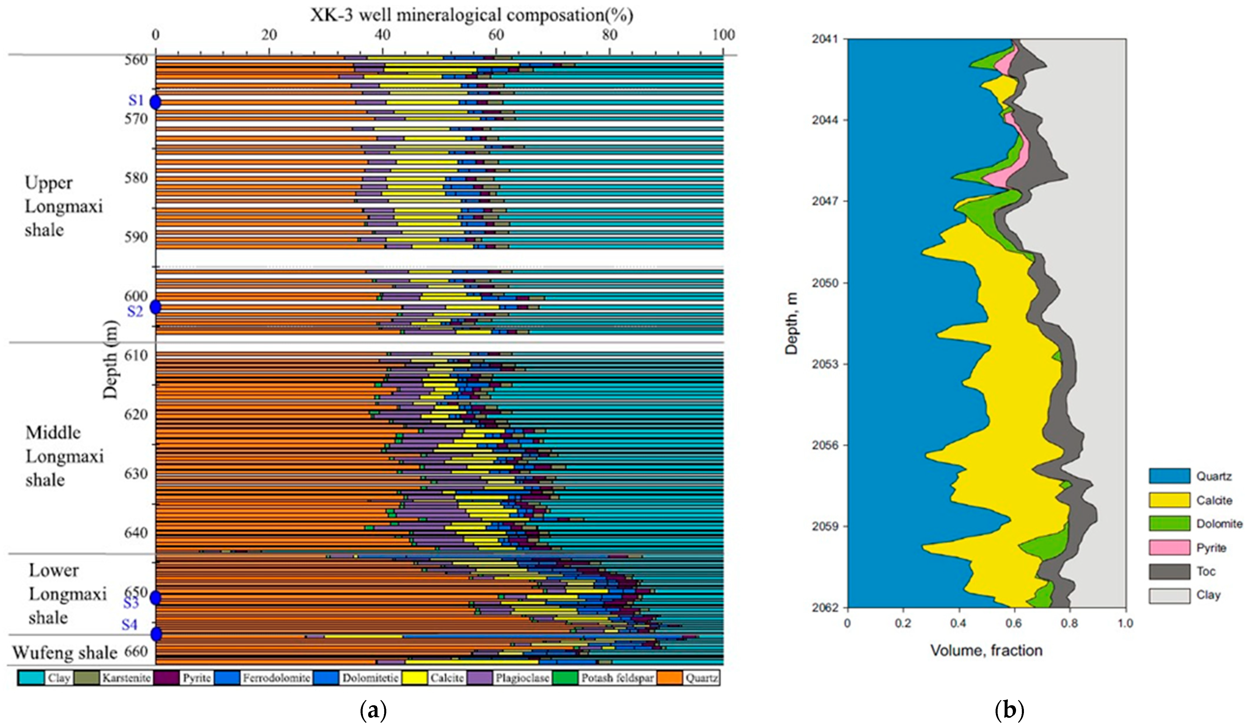
2. The Lithological Characteristics of Shale Rock
3. The Anisotropic Mechanical Behavior of Shale Specimens under Different Loading Conditions
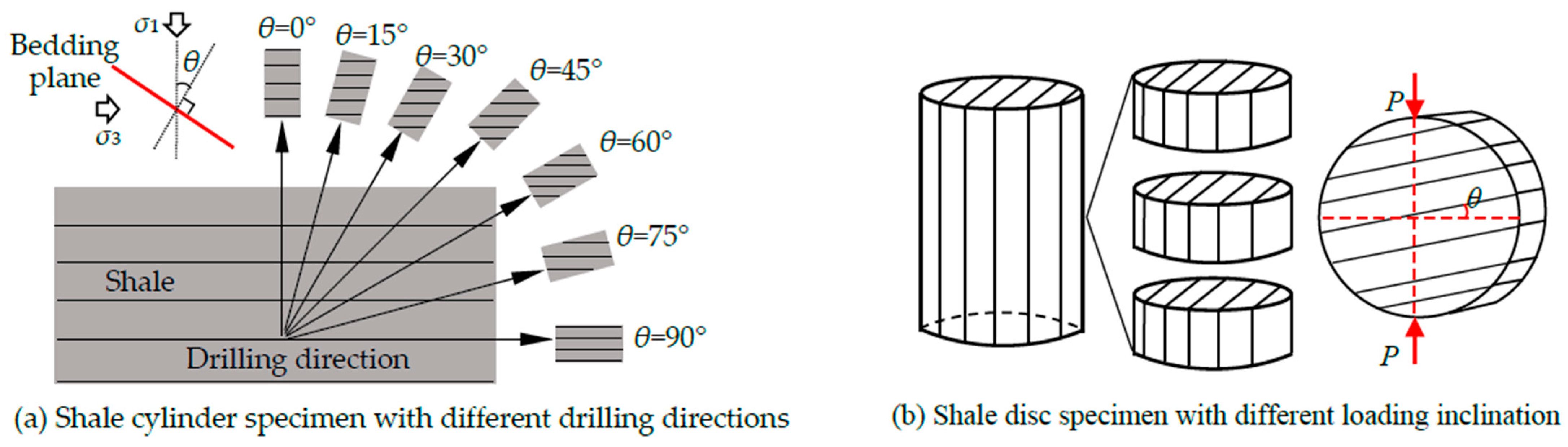
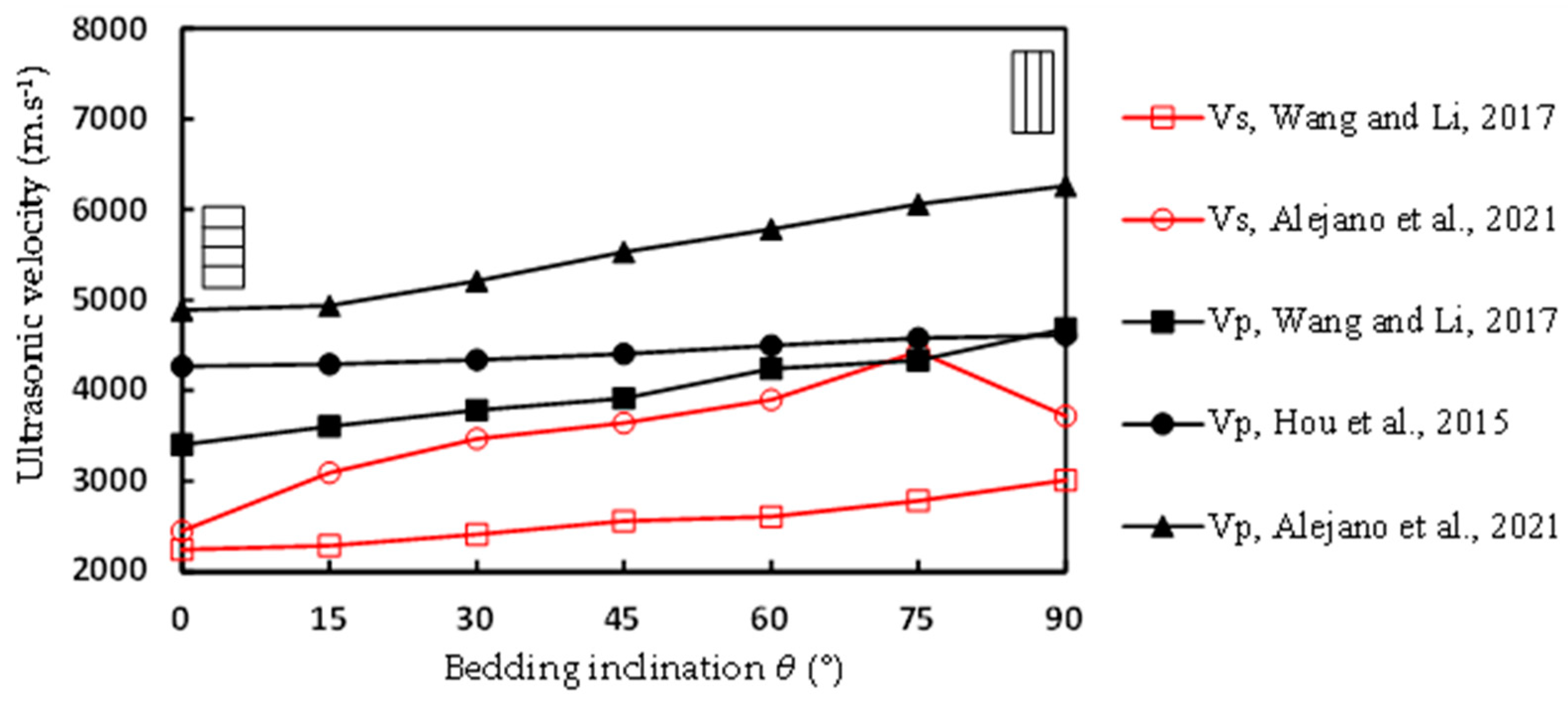
3.1. Ultrasonic Anisotropy of Shale Specimens
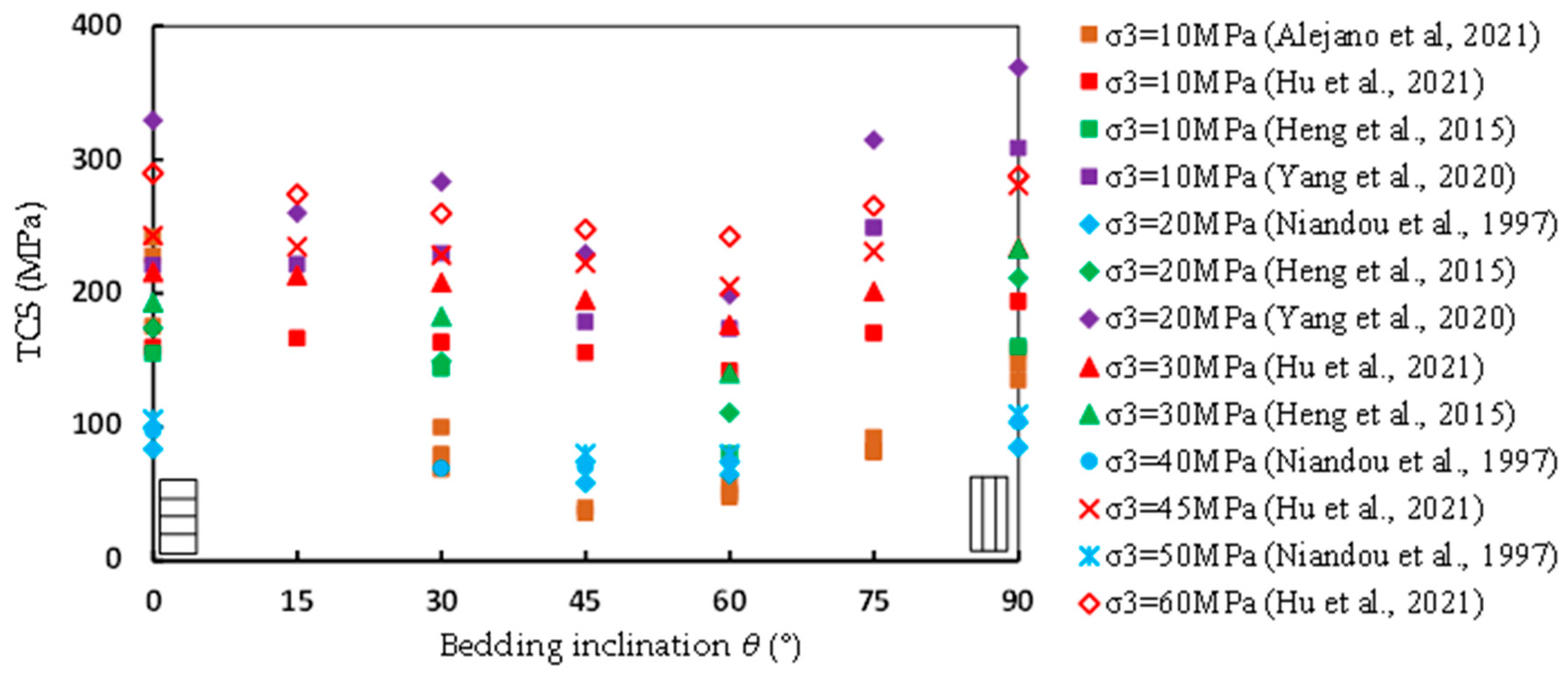
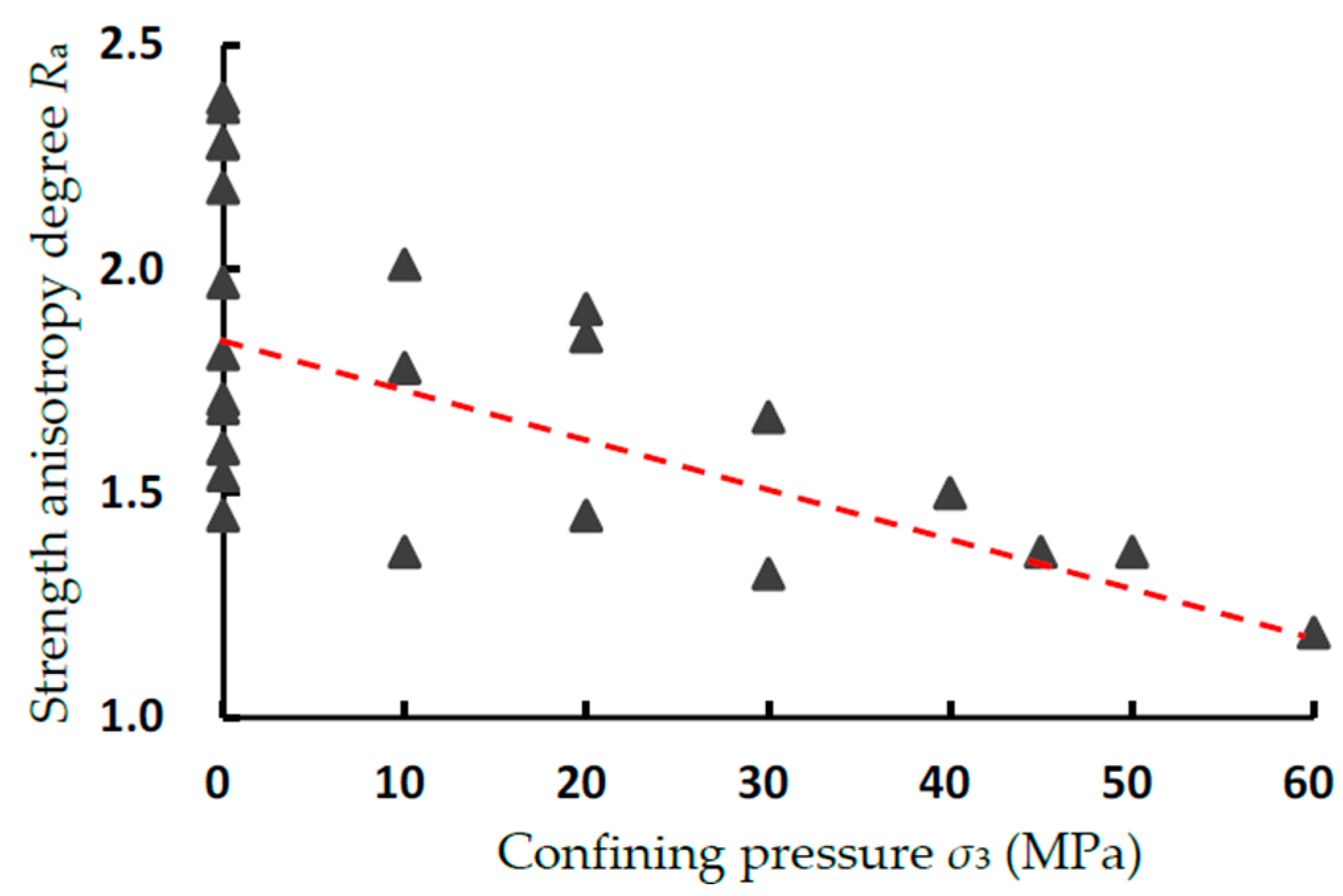
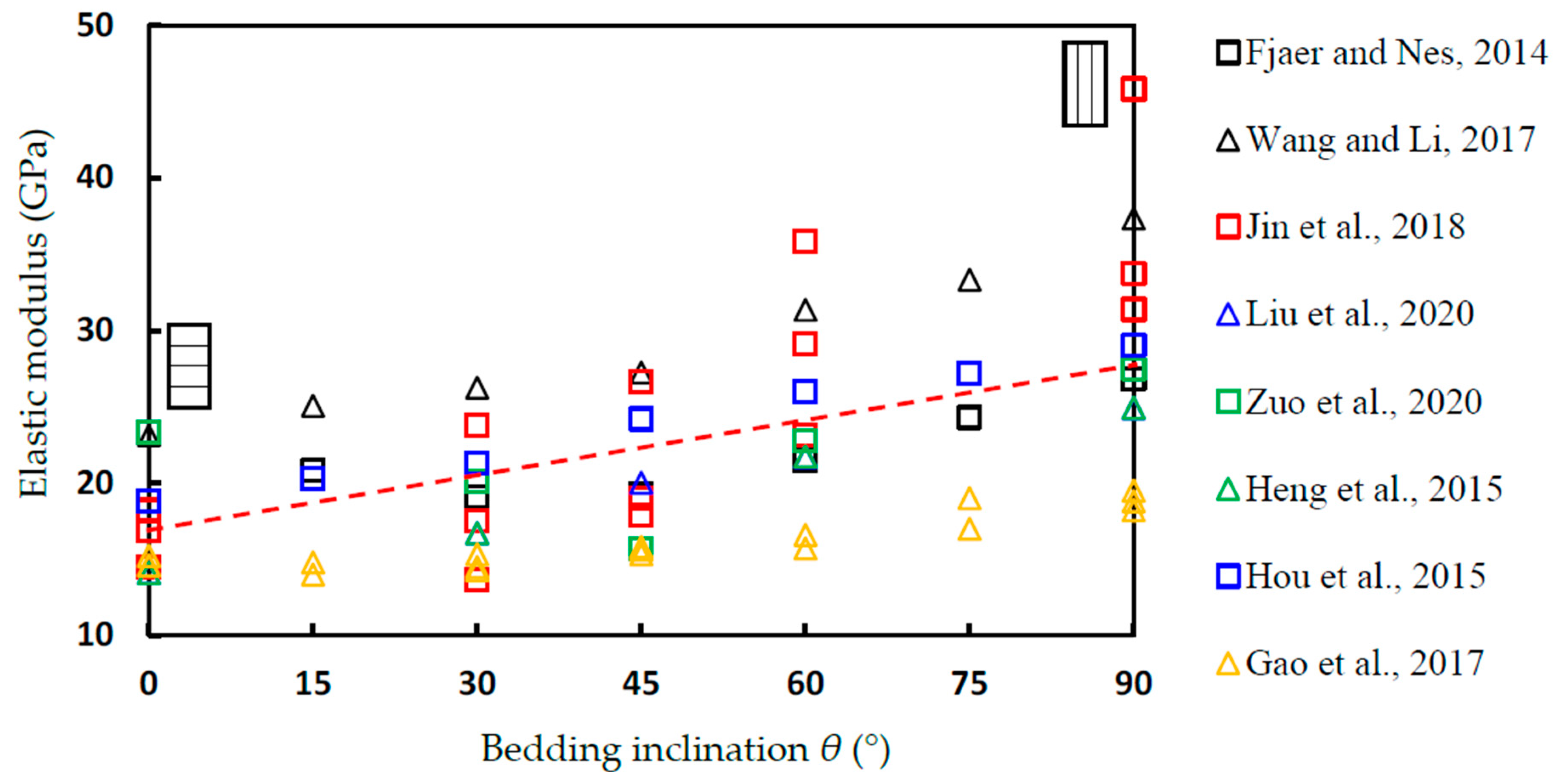
3.2. Uniaxial and Triaxial Compression Test
3.3. Tensile Properties under Brazilian Split Test
3.4. Fracture Toughness Anisotropy of Shale Specimens
4. The Relationship of Shale Mechanical Properties to Hydraulic Fracturing Evaluation
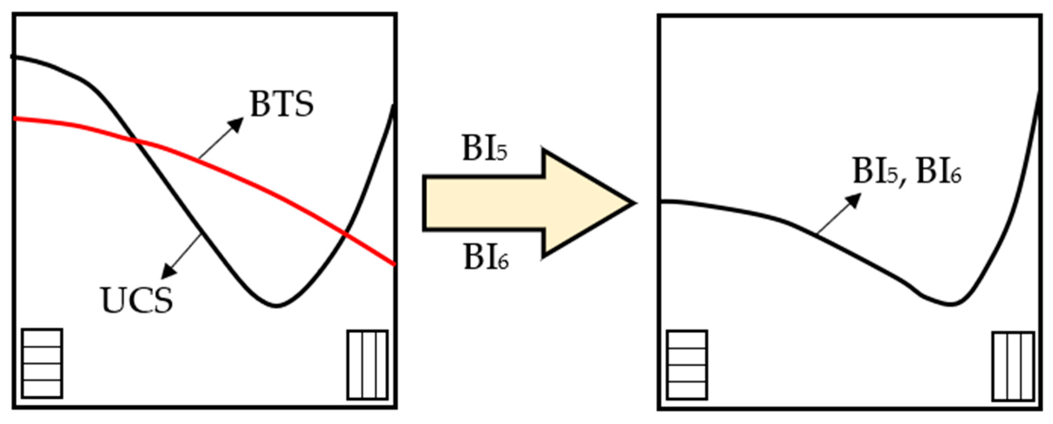
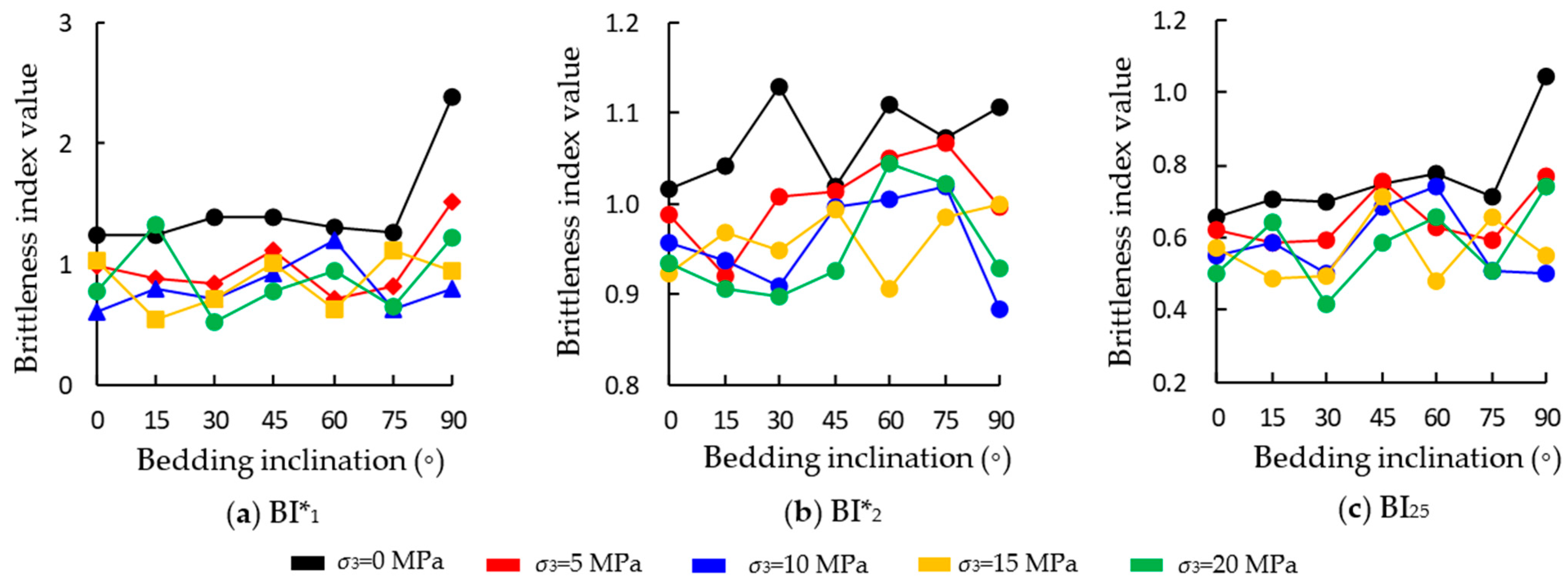
4.1. Quantitative Evaluation of Shale Brittleness Based on Mechanical Properties
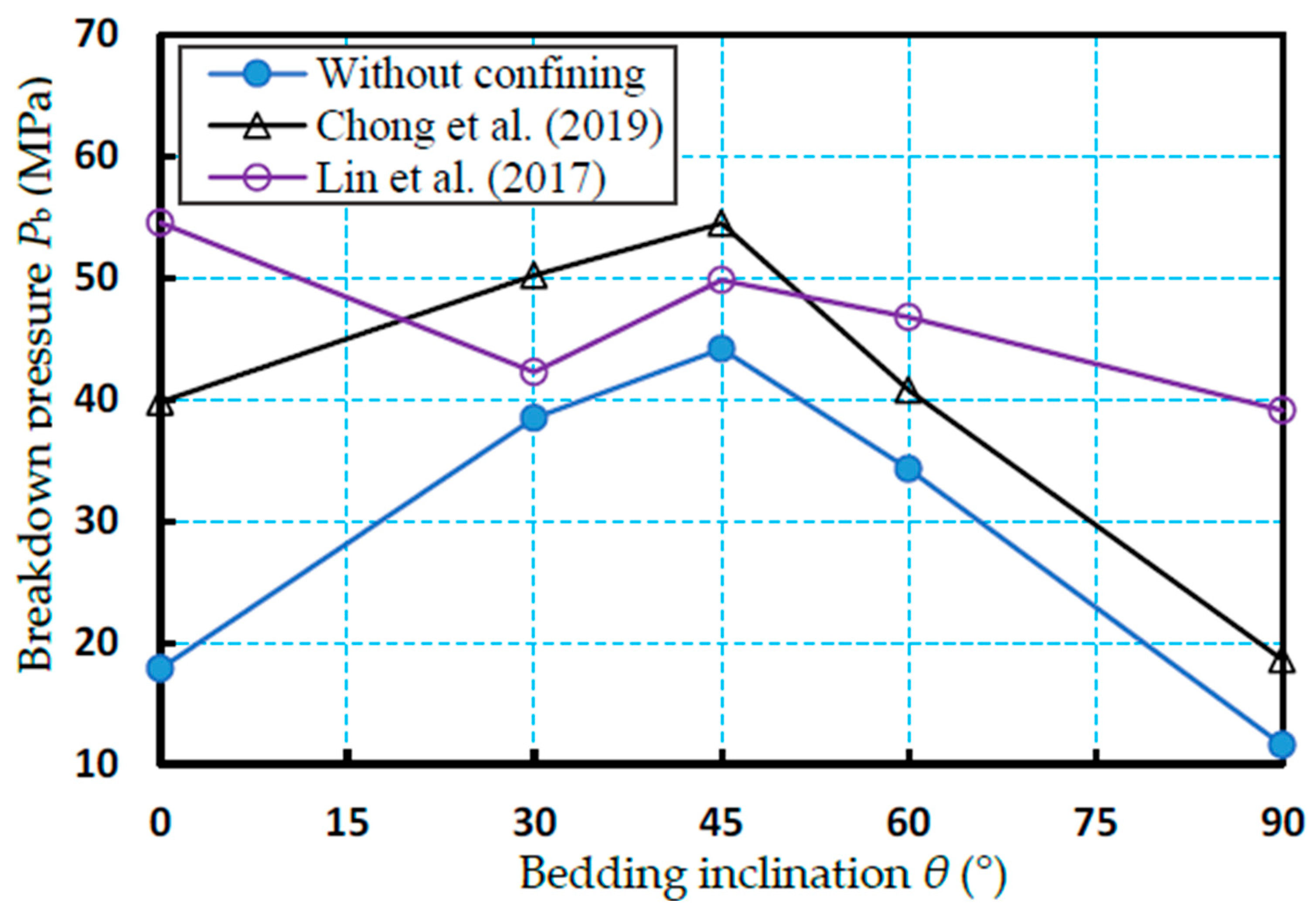
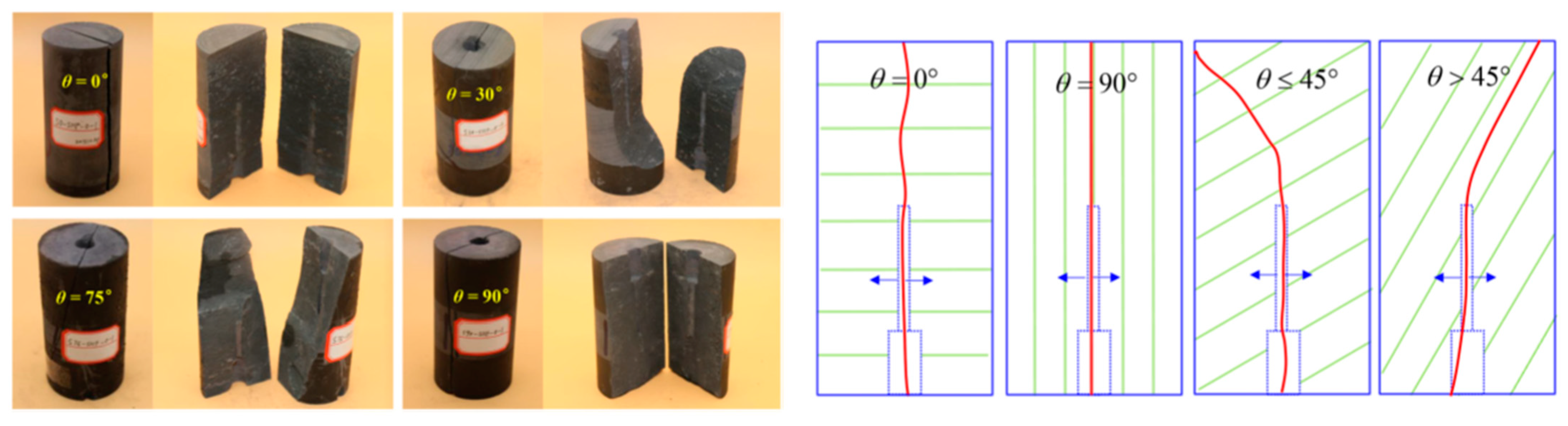
4.2. The Anisotropic Effect of Bedding Plane on Hydraulic Fracture Initiation and Propagation of Shale
5. Conclusions
Author Contributions
Funding
Conflicts of Interest
References
- Wang, Y.; Zhang, D.; Hu, Y.Z. Laboratory investigation of the effect of injection rate on hydraulic fracturing performance in artificial transversely laminated rock using 3D laser scanning. Geotech. Geol. Eng. 2019, 37, 2121–2133. [Google Scholar] [CrossRef]
- Yang, S.Q.; Yin, P.F.; Ranjith, P.G. Experimental study on mechanical behavior and brittleness characteristics of Longmaxi formation shale in Changning, Sichuan basin, China. Rock Mech. Rock Eng. 2020, 53, 2461–2483. [Google Scholar] [CrossRef]
- Saldungaray, P.; Palisch, T.T. Hydraulic fracture optimization in unconventional reservoirs. In Proceedings of the Society of Petroleum Engineers—SPE Middle East Unconventional Gas Conference and Exhibition, UGAS—Unlocking Unconventional Gas: New Energy in the Middle East, Abu Dhabi, United Arab Emirates, 23–25 January 2012. SPE-151128-MS. [Google Scholar]
- Nguyen, V.P.; Lian, H.; Rabczuk, T.; Bordas, S. Modelling hydraulic fractures in porous media using flow cohesive interface elements. Eng. Geol. 2017, 225, 68–82. [Google Scholar] [CrossRef]
- Taghichian, A.; Hashemalhoseini, H.; Zaman, M.; Yang, Z.Y. Geomechanical optimization of hydraulic fracturing in unconventional reservoirs: A semi-analytical approach. Int. J. Fract. 2018, 213, 107–138. [Google Scholar] [CrossRef]
- Jain, R. Natural resource development for science, technology, and environmental policy issues: The case of hydraulic fracturing. Clean Technol. Environ. Policy 2015, 17, 3–8. [Google Scholar] [CrossRef]
- Guo, C.H.; Xu, J.C.; Wei, M.Z.; Jiang, R.Z. Experimental Study and Numerical Simulation of Hydraulic Fracturing Tight Sandstone Reservoirs. Fuel 2015, 159, 334–344. [Google Scholar] [CrossRef]
- Ibanez, W.D.; Kronenberg, A.K. Experimental deformation of shale: Mechanical properties and microstructural indicators of mechanisms. Int. J. Rock Mech. Min. Sci. Geomech. Abstr. 1993, 30, 723–734. [Google Scholar] [CrossRef]
- Horsrud, P.; Sqonstebo, E.F.; Boe, R. Mechanical and petrophysical properties of North Sea shales. Int. J. Rock Mech. Min. Sci. 1998, 35, 1009–1020. [Google Scholar] [CrossRef]
- Al-Bazali, T.; Zhang, J.G.; Chenevert, M.E.; Sharm, M.M. Factors controlling the compressive strength and acoustic properties of shale when interacting with water-based fluids. Int. J. Rock Mech. Min. Sci. 2008, 45, 729–738. [Google Scholar] [CrossRef]
- Fjaer, E.; Nes, O.M. The Impact of Heterogeneity on the Anisotropic Strength of an Outcrop Shale. Rock Mech. Rock Eng. 2014, 47, 1603–1611. [Google Scholar] [CrossRef]
- Holt, R.M.; Larsen, I.; Fjaer, E.; Stenebraten, J.F. Comparing mechanical and ultrasonic behaviour of a brittle and a ductile shale: Relevance to prediction of borehole stability and verification of shale barriers. J. Pet. Sci. Eng. 2020, 187, 106746. [Google Scholar] [CrossRef]
- Gao, Q.; Tao, J.L.; Hu, J.Y.; Yu, X. Laboratory study on the mechanical behaviors of an anisotropic shale rock. J. Rock Mech. Geotech. Eng. 2015, 7, 213–219. [Google Scholar] [CrossRef]
- Amadei, B. Importance of anisotropy when estimating and measuring in situ stresses in rock. Int. J. Rock Mech. Min. Sci. 1996, 33, 293–325. [Google Scholar] [CrossRef]
- Chen, C.; Pan, E.; Amadei, B. Determination of deformability and tensile strength of anisotropic rock using Brazilian tests. Int. J. Rock Mech. Min. Sci. 1998, 35, 43–61. [Google Scholar] [CrossRef]
- Gale, J.F.W.; Reed, R.M.; Holder, J. Natural fractures in the Barnett Shale and their importance for hydraulic fracture treatments. AAPG Bull. 2007, 91, 603–622. [Google Scholar] [CrossRef]
- Gale, J.F.W.; Laubach, S.E.; Olson, J.E.; Eichhuble, P.; Fall, A. Natural Fractures in shale: A review and new observations. AAPG Bull. 2014, 98, 2165–2216. [Google Scholar] [CrossRef]
- Jones, L.E.A.; Wang, H.F. Ultrasonic velocities in Cretaceous shales from the Williston Basin. Geophysics 1981, 46, 288–297. [Google Scholar] [CrossRef]
- Johnston, J.E.; Christensen, N.I. Seismic anisotropy of shales. J. Geophys. Res. Solid Earth 1995, 100, 5991–6003. [Google Scholar] [CrossRef]
- Hornby, B.E. Experimental laboratory determination of the dynamic elastic properties of wet, drained shales. J. Geophys. Res. Solid Earth 1998, 103, 29945–29964. [Google Scholar] [CrossRef]
- Hornby, B.E.; Schwartz, L.M.; Hudson, J.A. Anisotropic effective-medium modeling of the elastic properties of shales. Geophysics 1994, 59, 1570–1583. [Google Scholar] [CrossRef]
- Holt, R.M.; Fjær, E.; Raaen, A.M.; Ringstad, C. Influence of stress state and stress history on acoustic wave propagation in sedimentary rocks. In Shear Waves in Marine Sediments; Springer: Dordrecht, The Netherlands, 1991; pp. 167–174. [Google Scholar]
- Sayers, C.M. Stress-dependent seismic anisotropy of shales. Geophysics 1999, 64, 93–98. [Google Scholar] [CrossRef]
- Vernik, L.; Landis, C. Elastic anisotropy of source rocks: Implications for hydrocarbon generation and primary migration. AAPG Bullet. 1996, 80, 531–544. [Google Scholar]
- Jin, Z.F.; Li, W.X.; Jin, C.R.; Hambleton, J.; Cusatis, G. Elastic, strength, and fracture properties of Marcellus shale. Int. J. Rock Mech. Min. Sci. 2018, 109, 124–137. [Google Scholar] [CrossRef]
- Loucks, R.G.; Reed, R.M.; Ruppel, S.C.; Hammes, U. Spectrum of pore types and networks in mudrocks and a descriptive classification for matrix-related mudrock pores. AAPG Bullet. 2012, 96, 1071–1098. [Google Scholar] [CrossRef]
- Sone, H.; Zoback, M.D. Mechanical properties of shale-gas reservoir rocks—Part 1: Static and dynamic elastic properties and anisotropy. Geophysics 2013, 78, 381–392. [Google Scholar] [CrossRef]
- Revil, A.; Grauls, D.; Brevart, O. Mechanical compaction of sand/clay mixtures. J. Geophys. Res. 2002, 107, 2293. [Google Scholar] [CrossRef]
- Crawford, B.R.; Faulkner, D.R.; Rutter, E.H. Strength, porosity, and permeability development during hydrostatic and shear loading of synthetic quartz-clay fault gouge. J. Geophys. Res. Solid Earth 2008, 113, B03207. [Google Scholar] [CrossRef]
- Kohli, A.H.; Zoback, M.D. Frictional properties of shale reservoir rocks. J. Geophys. Res. Solid Earth 2013, 118, 5109–5125. [Google Scholar] [CrossRef]
- Bai, B.J.; Elgmati, M.; Zhang, H.; Wei, M.Z. Rock characterization of Fayetteville shale gas plays. Fuel 2013, 105, 645–652. [Google Scholar] [CrossRef]
- Wang, J.X.; Xie, L.Z.; Xie, H.P.; Ren, L.; He, B.; Li, C.B.; Yang, Z.P.; Gao, C. Effect of layer orientation on acoustic emission characteristics of anisotropic shale in Brazilian tests. J. Nat. Gas Sci. Eng. 2016, 36, 1120–1129. [Google Scholar] [CrossRef]
- Hou, P.; Gao, F.; Yang, Y.G.; Zhang, Z.Z.; Zhang, X.X. Effect of bedding orientation on failure of black shale under Brazilian tests and energy analysis. Chin. J. Geotech. Eng. 2016, 38, 930–937. [Google Scholar]
- Li, C.B.; Gao, C.; Xie, H.P.; Li, N. Experimental investigation of anisotropic fatigue characteristics of shale under uniaxial cyclic loading. Int. J. Rock Mech. Min. Sci. 2020, 130, 104314. [Google Scholar] [CrossRef]
- Li, C.B.; Wang, J.; Xie, H.P. Anisotropic creep characteristics and mechanism of shale under elevated deviatoric stress. J. Pet. Sci. Eng. 2020, 185, 106670. [Google Scholar] [CrossRef]
- Heng, S.; Yang, C.H.; Zhang, B.P.; Guo, Y.T.; Wang, L.; Wei, Y.L. Experimental research on anisotropic properties of shale. Chin. J. Rock Soil Mech. 2015, 36, 609–616. [Google Scholar]
- Luo, Y.; Xie, H.P.; Ren, L.; Zhang, R.; Li, C.B.; Gao, C. Linear elastic fracture mechanics characterization of an anisotropic shale. Sci. Rep. 2018, 8, 8505. [Google Scholar] [CrossRef] [PubMed]
- Zou, Y.S.; Zhang, S.C.; Zhou, T.; Zhou, X.; Guo, T.K. Experimental investigation into hydraulic fracture network propagation in gas shales using CT scanning technology. Rock Mech. Rock Eng. 2016, 49, 33–45. [Google Scholar]
- Guo, T.K.; Zhang, S.C.; Qu, Z.Q.; Zhou, T.; Xiao, Y.S.; Gao, J. Experimental study of hydraulic fracturing for shale by stimulated reservoir volume. Fuel 2014, 128, 373–380. [Google Scholar] [CrossRef]
- Lin, C.; He, J.M.; Li, X.; Wan, X.L.; Zheng, B. An experimental investigation into the effects of the anisotropy of shale on hydraulic fracture propagation. Rock Mech. Rock Eng. 2017, 50, 543–554. [Google Scholar] [CrossRef]
- Masri, M.; Sibai, M.; Shao, J.F.; Mainguy, M. Experimental investigation of the effect of temperature on the mechanical behavior of Tournemire shale. Int. J. Rock Mech. Min. Sci. 2014, 70, 185–191. [Google Scholar] [CrossRef]
- Rybacki, E.; Reinicke, A.; Meier, T.; Makasi, M.; Dresen, G. What controls the mechanical properties of shale rocks?—Part I: Strength and young’s modulus. J. Pet. Sci. Eng. 2015, 135, 702–722. [Google Scholar] [CrossRef]
- Rybacki, E.; Meier, T.; Dresen, G. What controls the mechanical properties of shale rocks?—Part II: Brittleness. J. Pet. Sci. Eng. 2016, 144, 39–58. [Google Scholar] [CrossRef]
- Mokhtari, M.; Alqahtani, A.A.; Tutuncu, A.N. Failure Behavior of Anisotropic Shales. In Proceedings of the 47th US Rock Mechanics/Geomechanics Symposium, San Francisco, CA, USA, 23–26 June 2013. [Google Scholar]
- Heng, S.; Yang, C.H.; Guo, Y.T.; Wang, C.Y.; Wang, L. Influence of bedding planes on hydraulic fracture propagation in shale formations. Chin. J. Rock Mech. Eng. 2015, 34, 228–237. [Google Scholar]
- Heng, S.; Guo, Y.T.; Yang, C.H.; Daemen, J.J.K.; Li, Z. Experimental and theoretical study of the anisotropic properties of shale. Int. J. Rock Mech. Min. Sci. 2015, 74, 58–68. [Google Scholar] [CrossRef]
- Jarvie, D.M.; Hill, R.J.; Ruble, T.E.; Pollastro, R.M. Unconventional shale-gas systems: The Mississippian Barnett shale of north-central Texas as one model for thermogenic shale-gas assessment. AAPG Bull. 2007, 91, 475–499. [Google Scholar] [CrossRef]
- Li, Q.H.; Chen, M.; Jin, Y.; Wang, F.P.; Hou, B.; Zhang, B. Indoor evaluation method for shale brittleness and improvement. Chin. J. Rock Mech. Eng. 2012, 31, 1680–1685. [Google Scholar]
- Kivi, I.R.; Ameri, M.; Molladavoodi, H. Shale brittleness evaluation based on energy balance analysis of stress-strain curves. J. Pet. Sci. Eng. 2018, 167, 1–19. [Google Scholar] [CrossRef]
- Qian, K.R.; Liu, T.; Liu, J.Z.; Liu, X.W.; He, Z.L.; Jiang, D.J. Construction of a novel brittleness index equation and analysis of anisotropic brittleness characteristics for unconventional shale formations. Pet. Sci. 2020, 17, 70–85. [Google Scholar] [CrossRef]
- Huang, X.R.; Huang, J.P.; Li, Z.C.; Yang, Q.Y.; Sun, Q.X.; Cui, W. Brittleness index and seismic rock physics model for anisotropic tight-oil sandstone reservoirs. Appl. Geophys. 2015, 12, 11–22. [Google Scholar] [CrossRef]
- Schmidt, R.A.; Huddle, C.W. Fracture Mechanics of Oil Shale: Some Preliminary Results; Report No. SAND-76-0727; Sandia Labs: Albuquerque, NM, USA, 1997; 29p. [Google Scholar] [CrossRef]
- Lee, H.P.; Olson, J.E.; Holder, J.; Gale, J.F.W.; Myers, R.D. The interaction of propagating opening mode fractures with preexisting discontinuities in shale. J. Geophys. Res. Solid Earth 2015, 120, 169–181. [Google Scholar] [CrossRef]
- Chandler, M.R.; Meredith, P.G.; Brantut, N.; Crawford, B.R. Fracture toughness anisotropy in shale. J. Geophys. Res. Solid Earth 2016, 121, 1706–1729. [Google Scholar] [CrossRef]
- Yin, S.; Lv, D.W.; Jin, L.; Ding, W.L. Experimental analysis and application of the effect of stress on continental shale reservoir brittleness. J. Geophys. Eng. 2018, 15, 478–494. [Google Scholar] [CrossRef]
- Zhao, Y.; He, P.F.; Zhang, Y.F.; Wang, C.L. A new criterion for a toughness-dominated hydraulic fracture crossing a natural frictional interface. Rock Mech. Rock Eng. 2019, 52, 2617–2629. [Google Scholar] [CrossRef]
- Zhao, Y.; Zhang, Y.F.; He, P.F. A composite criterion to predict subsequent intersection behavior between a hydraulic fracture and a natural fracture. Eng. Fract. Mech. 2019, 209, 61–78. [Google Scholar] [CrossRef]
- Kou, M.M.; Liu, X.R.; Tang, S.D.; Wang, Y.T. 3-D X-ray computed tomography on failure characteristics of rock-like materials under coupled hydro-mechanical loading. Theor. Appl. Fract. Mech. 2019, 104, 102396. [Google Scholar] [CrossRef]
- Kou, M.M.; Liu, X.R.; Wang, Y.T. Study on rock fracture behavior under hydromechanical loading by 3-D digital reconstruction. Struct. Eng. Mech. 2020, 74, 283–296. [Google Scholar]
- Zhang, Y.F.; Zhao, Y.; Yang, H.Q.; Wang, C.L. A semianalytical solution for a Griffith crack nonuniformly pressurized by internal fluid. Rock Mech. Rock Eng. 2020, 53, 2439–2460. [Google Scholar] [CrossRef]
- Zhao, Y.; Zhang, Y.F.; Wang, C.L.; Liu, Q. Hydraulic fracturing characteristics and evaluation of fracturing effectiveness under different anisotropic angles and injection rates: An experimental investigation in absence of confining pressure. J. Nat. Gas Sci. Eng. 2022, 97, 104343. [Google Scholar] [CrossRef]
- Yaalon, D.H. Mineral composition of average shale. Clay Min. Bull. 1962, 5, 31–36. [Google Scholar] [CrossRef]
- Sliwinski, J.; Harrington, J.; Power, M.; Hughes, P.; Yeung, B. A high definition mineralogical examination of potential gas shales. Abstract Volume. In Proceedings of the AAPG—Annual Convention and Exhibition, New Orleans, LA, USA, 11–14 April 2010; p. 239. [Google Scholar]
- Lyu, Q.; Shi, J.D.; Ranjith, P.G. Effects of testing method, lithology and fluid-rock interactions on shale permeability: A review of laboratory measurements. J. Nat. Gas Sci. Eng. 2020, 78, 1033023. [Google Scholar] [CrossRef]
- Minaeian, V.; Dewhurst, D.N.; Rasouli, V. Deformational behaviour of a clay-rich shale with variable water saturation under true triaxial stress conditions. Geomech. Energy Environ. 2017, 11, 1–13. [Google Scholar] [CrossRef]
- Wu, C.J.; Tuo, J.C.; Zhang, L.F.; Zhang, M.F.; Li, J.; Liu, Y.; Qian, Y. Pore characteristics differences between clay-rich and clay-poor shales of the Lower Cambrian Niutitang Formation in the Northern Guizhou area, and insights into shale gas storage mechanisms. Int. J. Coal Geol. 2017, 178, 13–25. [Google Scholar] [CrossRef]
- Zhang, J.J.; Kamenov, A.; Zhu, D.; Hill, A.D. Development of new testing procedures to measure propped fracture conductivity considering water damage in clay-rich shale reservoirs: An example of the Barnett Shale. J. Pet. Sci. Eng. 2015, 135, 352–359. [Google Scholar] [CrossRef]
- Amalokwu, K.; Spikes, K.; Wolf, K. A simple effective medium approach for the bulk electrical and elastic properties of organic-rich shales. J. Appl. Geophys. 2019, 169, 98–108. [Google Scholar] [CrossRef]
- Wang, Y.P.; Liu, X.J.; Liang, L.X.; Xiong, J. Experimental study on the damage of organic-rich shale during water-shale interaction. J. Nat. Gas Sci. Eng. 2020, 74, 103103. [Google Scholar] [CrossRef]
- Wei, M.M.; Zhang, L.; Xiong, Y.Q.; Peng, P.A. Main factors influencing the development of nanopores in over-mature, organic-rich shales. Int. J. Coal Geol. 2019, 212, 103233. [Google Scholar] [CrossRef]
- Ilgen, A.G.; Aman, M.; Espinoza, D.N.; Rodriguez, M.A.; Griego, J.M.; Dewers, T.A.; Feldman, J.D.; Stewart, T.A.; Choens, R.C.; Wilson, J. Shale-brine-CO2 interactions and the long-term stability of carbonate-rich shale caprock. Int. J. Greenh. Gas Control 2018, 78, 244–253. [Google Scholar] [CrossRef]
- Teklu, T.W.; Abass, H.H.; Hanashmooni, R.; Carratu, J.C.; Ermila, M. Experimental investigation of acid imbibition on matrix and fractured carbonate rich shales. J. Nat. Gas Sci. Eng. 2017, 45, 706–725. [Google Scholar] [CrossRef]
- Rickman, R.; Mullen, M.J.; Petre, J.E.; Grieser, W.V.; Kundert, D. A practical use of shale petrophysics for stimulation design optimization: All shale plays are not clones of the Barnett shale. In Proceedings of the SPE Annual Technical Conference and Exhibition, Society of Petroleum Engineers, Denver, CO, USA, 21–24 September 2008. [Google Scholar]
- Civan, F. Reservoir Formation Damage; Gulf Publishing Company: Houston, TX, USA, 2007. [Google Scholar]
- Loucks, R.G.; Ruppel, S.C. Mississippian Barnett Shale: Lithofacies and depositional setting of a deep-water shale-gas succession in the Fort Worth Basin, Texas. AAPG Bull. 2007, 91, 579–601. [Google Scholar] [CrossRef]
- Li, G.F.; Jin, Z.J.; Li, X.; Liu, K.Q.; Yang, W.C.; Qiao, M.T.; Zhou, T.T.; Sun, X.K. Experimental study on mechanical properties and fracture characteristics of shale layered samples with different mineral components under cyclic loading. Mar. Pet. Geol. 2023, 150, 106114. [Google Scholar] [CrossRef]
- Wang, Y.; Li, C.H. Investigation of the p- and s-wave velocity anisotropy of a Longmaxi formation shale by real-time ultrasonic and mechanical experiments under uniaxial deformation. J. Pet. Sci. Eng. 2017, 158, 253–267. [Google Scholar] [CrossRef]
- Niandou, H.; Shao, J.F.; Henry, J.P.; Fourmaintraux, D. Laboratory investigation of the mechanical behaviour of Tournemire shale. Int. J. Rock Mech. Min. Sci. 1997, 34, 3–16. [Google Scholar] [CrossRef]
- Jia, Y.Z.; Tang, J.R.; Lu, Y.Y.; Lu, Z.H. Laboratory geomechanical and petrophysical characterization of Longmaxi shale properties in Lower Silurian Formation, China. Mar. Pet. Geol. 2020, 124, 104800. [Google Scholar] [CrossRef]
- Liu, Y.; Ma, T.; Wu, H.; Chen, P. Investigation on mechanical behaviors of shale cap rock for geological energy storage by linking macroscopic to mesoscopic failures. J. Energy Storage 2020, 29, 101326. [Google Scholar] [CrossRef]
- Yang, S.Q.; Yin, P.F.; Li, B.; Yang, D.S. Behavior of transversely isotropic shale observed in triaxial tests and Brazilian disc tests. Int. J. Rock Mech. Min. Sci. 2020, 133, 104435. [Google Scholar] [CrossRef]
- Brahma, J.; Sircar, A. Estimation of the effect of anisotropy on Young’s moduli and Poisson’s ratios of sedimentary rocks using core samples in western and central part of Tripura, India. Int. J. Geosci. 2014, 05, 184–195. [Google Scholar] [CrossRef]
- Lo, T.W.; Coyner, K.B.; Toksoz, M.N. Experimental determination of elastic anisotropy of Berea sandstone, Chicopee shale, and Chelmsford granite. Geophysics 1986, 51, 164–171. [Google Scholar] [CrossRef]
- Allan, A.M.; Kanitpanyacharoen, W.; Vanorio, T. A multiscale methodology for the analysis of velocity anisotropy in organic-rich shale. Geophysics 2015, 80, 73–88. [Google Scholar] [CrossRef]
- Alejano, L.R.; González-Fernández, M.A.; Estévez-Ventosa, X.; Song, F.; Delgado-Martín, J.; Muoz-Ibáez, A.; Gonzalez-Molano, N.; Alvarellos, J. Anisotropic deformability and strength of slate from NW-Spain. Int. J. Rock Mech. Min. Sci. 2021, 148, 104923. [Google Scholar] [CrossRef]
- Hou, Z.K.; Yang, C.H.; Guo, Y.T.; Zhang, B.P.; Wei, Y.L.; Heng, S.; Wang, L. Experimental study on anisotropic properties of Longmaxi formation shale under uniaxial compression. Chin. J. Rock Soil Mech. 2015, 36, 2541–2550. [Google Scholar]
- Dewhurst, D.N.; Siggins, A.F.; Sarout, J.; Raven, M.D.; Nordgård-Bolås, H.M. Geomechanical and ultrasonic characterization of a Norwegian Sea shale. Geophysics 2011, 76, 101–111. [Google Scholar] [CrossRef]
- Zhubayev, A.; Houben, M.E.; Smeulders, D.M.J.; Barnhoorn, A. Ultrasonic velocity and attenuation anisotropy of shales, Whitby, United Kingdom. Geophysics 2015, 81, 45–56. [Google Scholar] [CrossRef]
- Jin, G.; Ali, S.S.; Abdullah, A.; Dhamen, A. Mechanical anisotropy of unconventional shale—Build the correct relationship between static and dynamic properties. In Proceedings of the 2016 Abu Dhabi International Petroleum Exhibition & Conference, Society of Petroleum Engineers, Abu Dhabi, United Arab Emirates, 7–10 November 2016; pp. 1–9. [Google Scholar]
- Iferobia, C.C.; Ahmad, M. A review on the experimental techniques and applications in the geomechanical evaluation of shale gas reservoirs. J. Nat. Gas Sci. Eng. 2020, 74, 103090. [Google Scholar] [CrossRef]
- Rasouli, V. Geomechanics of gas shales. In Fundamentals of Gas Shale Reservoirs; Rezaee, R., Ed.; John Wiley & Sons, Inc.: Hoboken, NJ, USA, 2015; pp. 169–190. [Google Scholar]
- Panfiloff, A. Experimental Evaluation of Dynamic Elastic Properties and Anisotropy in Shales; Colorado School of Mines: Golden, CO, USA, 2016. [Google Scholar]
- Yin, P.F.; Yang, S.Q. Experimental study on strength and failure behavior of transversely isotropic rock-like material under uniaxial compression. Geomech. Geophys. Geo-Energy Geo-Resour. 2020, 6, 44. [Google Scholar] [CrossRef]
- Kuila, U.; Dewhurst, D.N.; Siggins, A.F.; Raven, M.D. Stress anisotropy and velocity anisotropy in low porosity shale. Tectonophysics 2011, 50, 34–44. [Google Scholar] [CrossRef]
- Cho, J.W.; Kim, H.; Jeon, S.; Min, K.B. Deformation and strength anisotropy of Asan gneiss, Boryeong shale, and Yeoncheon schist. Int. J. Rock Mech. Min. Sci. 2012, 50, 158–169. [Google Scholar] [CrossRef]
- Kim, H.; Cho, J.W.; Song, I.; Min, K.B. Anisotropy of elastic moduli, p-wave velocities, and thermal conductivities of Asan gneiss, Boryeong shale, and Yeoncheon schist in Korea. Eng. Geol. 2012, 147–148, 68–77. [Google Scholar] [CrossRef]
- Yang, S.Q.; Yin, P.F.; Huang, Y.H. Experiment and discrete element modelling on strength, deformation and failure behaviour of shale under Brazilian compression. Rock Mech. Rock Eng. 2019, 52, 4339–4359. [Google Scholar] [CrossRef]
- Josh, M.; Esteban, L.; Piane, C.D.; Sarout, J.; Dewhurst, D.N.; Clennell, M.B. Laboratory characterisation of shale properties. J. Pet. Sci. Eng. 2012, 88–89, 107–124. [Google Scholar] [CrossRef]
- Wu, S.; Ge, H.K.; Wang, X.Q.; Meng, F.B. Shale failure processes and spatial distribution of fractures obtained by AE monitoring. J. Nat. Gas Sci. Eng. 2017, 41, 82–92. [Google Scholar] [CrossRef]
- Li, X.L.; Lei, X.; Li, Q.; Li, X. Experimental investigation of Sinian shale rock under triaxial stress monitored by ultrasonic transmission and acoustic emission. J. Nat. Gas Sci. Eng. 2017, 43, 110–123. [Google Scholar] [CrossRef]
- Nasseri, M.H.; Rao, K.S.; Ramamurthy, T. Failure mechanism in schistose rocks. Int. J. Rock Mech. Min. Sci. 1997, 34, 219. [Google Scholar] [CrossRef]
- Nasseri, M.H.; Rao, K.S.; Ramamurthy, T. Anisotropic strength and deformational behavior of Himalayan schists. Int. J. Rock Mech. Min. Sci. 2003, 40, 3–23. [Google Scholar] [CrossRef]
- Hakala, M.; Kuula, H.; Hudson, J.A. Estimating the transversely isotropic elastic intact rock properties for in situ stress measurement data reduction: A case study of the Olkiluoto mica gneiss, Finland. Int. J. Rock Mech. Min. Sci. 2007, 44, 14–46. [Google Scholar] [CrossRef]
- Yin, P.F.; Yang, S.Q. Experimental investigation of the strength and failure behavior of layered sandstone under uniaxial compression and Brazilian testing. Acta Geophys. 2018, 66, 585–605. [Google Scholar] [CrossRef]
- Ramamurthy, T. Strength, modulus responses of anisotropic rocks. In Compressive Rock Engineering; Hudson, J.A., Ed.; Pergamon: Oxford, UK, 1993; Volume 1, pp. 313–329. [Google Scholar]
- Gao, C.; Xie, L.Z.; Xie, H.P.; He, B.; Jin, W.C.; Li, F.; Yang, Z.P.; Sun, Y.Z. Estimation of the equivalent elastic modulus in shale formation: Theoretical model and experiment. J. Pet. Sci. Eng. 2017, 151, 468–479. [Google Scholar] [CrossRef]
- Zuo, J.P.; Lu, J.F.; Ghandriz, R.; Wang, J.T.; Li, Y.H.; Zhang, X.Y.; Li, J.; Li, H.T. Mesoscale fracture behavior of Longmaxi outcrop shale with different bedding angles: Experimental and numerical investigations. J. Rock Mech. Geotech. Eng. 2020, 12, 297–309. [Google Scholar] [CrossRef]
- Hu, J.J.; Gao, C.; Xie, H.P.; Wang, J.; Li, M.H.; Li, C.B. Anisotropic characteristics of the energy index during the shale failure process under triaxial compression. J. Nat. Gas Sci. Eng. 2021, 95, 104219. [Google Scholar] [CrossRef]
- Jaeger, J.C. Shear failure of transversely isotropic rock. Geol. Mag. 1960, 97, 65–72. [Google Scholar] [CrossRef]
- Hoek, E.; Brown, E.T. Underground Excavations in Rock; Institution of Mining and Metallurgy: London, UK, 1980. [Google Scholar]
- Rao, K.S.; Rao, G.V.; Ramamurthy, T. A strength criterion for anisotropic rocks. Indian Geotech. J. 1986, 16, 317–333. [Google Scholar]
- Ramamurthy, T.; Rao, G.V.; Singh, J. A strength criterion for anisotropic rocks. In Proceedings of the Fifth Australia–New Zealand Conference on Geomechanics, Sydney, Australia, 22–26 August 1988; Volume 1, pp. 253–257. [Google Scholar]
- Tien, Y.M.; Kuo, M.C. A failure criterion for transversely isotropic rocks. Int. J. Rock Mech. Min. Sci. 2001, 38, 399–412. [Google Scholar] [CrossRef]
- Saeidi, O.; Vaneghi, R.G.; Rasouli, V.; Gholami, R. A modified empirical criterion for strength of transversely anisotropic rocks with metamorphic origin. Bull. Eng. Geol. Environ. 2013, 72, 257–269. [Google Scholar] [CrossRef]
- Saeidi, O.; Vaneghi, R.G.; Rasouli, V.; Gholami, R.; Torabi, S.R. A modified failure criterion for transversely isotropic rocks. Geosci. Front. 2014, 5, 215–225. [Google Scholar] [CrossRef]
- Singh, M.; Samadhiya, N.K.; Kumar, A. A nonlinear criterion for triaxial strength of inherently anisotropic rocks. Rock Mech. Rock Eng. 2015, 48, 1387–1405. [Google Scholar] [CrossRef]
- Shi, X.C.; Yang, X.; Meng, X.F. An anisotropic strength model for layered rocks considering planes of weakness. Rock Mech. Rock Eng. 2016, 49, 3783–3792. [Google Scholar] [CrossRef]
- Rafiai, H. New empirical polyaxial criterion for rock strength. Int. J. Rock Mech. Min. Sci. 2011, 48, 922–931. [Google Scholar] [CrossRef]
- Chen, L.; Shao, J.F.; Huang, H.W. Coupled elastoplastic damage modeling of anisotropic rocks. Comput. Geotech. 2010, 37, 187–194. [Google Scholar] [CrossRef]
- Chen, L.; Shao, J.F.; Zhu, Q.Z.; Duveau, G. Induced anisotropic damage and plasticity in initially anisotropic sedimentary rocks. Int. J. Rock Mech. Min. Sci. 2012, 51, 13–23. [Google Scholar] [CrossRef]
- Yao, C.; Jiang, Q.H.; Shao, J.F.; Zhou, C.B. A discrete approach for modeling damage and failure in anisotropic cohesive brittle materials. Eng. Fract. Mech. 2016, 155, 102–118. [Google Scholar] [CrossRef]
- Qi, M.; Giraud, A.; Colliat, J.B.; Shao, J.F. A numerical damage model for initially anisotropic materials. Int. J. Solids Struct. 2016, 100–101, 245–256. [Google Scholar] [CrossRef]
- Qi, M.; Shao, J.F.; Giraud, A.; Zhu, Q.Z.; Colliat, J.B. Damage and plastic friction in initially anisotropic quasi brittle materials. Int. J. Plast. 2016, 82, 260–282. [Google Scholar] [CrossRef]
- Tien, Y.M.; Kuo, M.C.; Juang, C.H. An experimental investigation of the failure mechanism of simulated transversely isotropic rocks. Int. J. Rock Mech. Min. Sci. 2006, 43, 1163–1181. [Google Scholar] [CrossRef]
- Deng, J.X.; Shi, G.; Liu, R.X.; Yu, J. Analysis of the velocity anisotropy and its affection factors in shale and mudstone. Chin. J. Geophys. 2004, 47, 862–868. [Google Scholar]
- Zhao, C.X.; Liu, J.F.; Xu, D.; Zhang, L.Q.; Lyu, C.; Ren, Y. Investigation on Mechanical Properties, AE Characteristics, and Failure Modes of Longmaxi Formation Shale in Changning, Sichuan Basin, China. Rock Mech. Rock Eng. 2023, 56, 1239–1272. [Google Scholar] [CrossRef]
- Amadei, B.; Rogers, J.D.; Goodman, R.E. Elastic Constants and Tensile Strength of Anisotropic Rocks. In Proceedings of the 5th ISRM Congress, Melbourne, Australia, 10–15 April 1983. ISRM-5CONGRESS-1983-030. [Google Scholar]
- Lekhnitskii, S.G. Anisotropic Plates; Gordon and Breach: New York, NY, USA, 1968. [Google Scholar]
- Tavallali, A.; Vervoort, A. Failure of transversely isotropic rock material: Effect of layer orientation and material properties. In Proceedings of the 6th International Symposium on Ground Support in Mining and Civil Engineering Construction, Cape Town, South Africa, 30 March–3 April 2008; pp. 317–328. [Google Scholar]
- Tavallali, A.; Vervoort, A. Failure of layered sandstone under Brazilian test conditions: Effect of micro-scale parameters on macro-scale behaviour. Rock Mech. Rock Eng. 2010, 43, 641–653. [Google Scholar] [CrossRef]
- Tavallali, A.; Vervoort, A. Effect of layer orientation on the failure of layered sandstone under Brazilian test conditions. Int. J. Rock Mech. Min. Sci. 2010, 47, 313–322. [Google Scholar] [CrossRef]
- Tavallali, A.; Vervoort, A. Behaviour of layered sandstone under Brazilian test conditions: Layer orientation and shape effects. J. Rock Mech. Geotech. Eng. 2013, 5, 366–377. [Google Scholar] [CrossRef]
- Vervoort, A.; Min, K.B.; Konietzky, H.; Cho, J.W.; Debecker, B.; Din, Q.D.; Frühwirt, T.; Tavallali, A. Failure of transversely isotropic rock under Brazilian test conditions. Int. J. Rock Mech. Min. Sci. 2014, 70, 343–352. [Google Scholar] [CrossRef]
- Tan, X.; Konietzky, H.; Frühwirt, T.; Dan, D.Q. Brazilian tests on transversely isotropic rocks: Laboratory testing and numerical simulations. Rock Mech. Rock Eng. 2015, 48, 1341–1351. [Google Scholar] [CrossRef]
- Yang, Z.P.; He, B.; Xie, L.Z.; Li, C.B.; Wang, J. Strength and failure modes of shale based on Brazilian test. Chin. J. Rock Soil Mech. 2015, 36, 3447–3464. [Google Scholar]
- Hou, P.; Gao, F.; Yang, Y.G.; Zhang, Z.Z.; Gao, Y.N.; Zhang, X.X.; Zhang, J. Effect of bedding plane direction on acoustic emission characteristics of shale in Brazilian tests. Chin. J. Rock Soil Mech. 2016, 37, 1603–1612. [Google Scholar]
- Du, M.P.; Pan, P.Z.; Ji, W.W.; Zhang, Z.H.; Gao, Y.H. Time-space laws of failure process of carbonaceous shale in Brazilian split test. Chin. J. Rock Soil Mech. 2016, 37, 3437–3446. [Google Scholar]
- He, J.; Afolagboye, L.O. Influence of layer orientation and interlayer bonding force on the mechanical behavior of shale under Brazilian test conditions. Acta Mech. Sin. 2018, 34, 349–358. [Google Scholar] [CrossRef]
- Simpson, N.D.J.; Stroisz, A.; Bauer, A.; Vervoort, A.; Holt, R.M. Failure mechanics of anisotropic shale during Brazilian tests. In Proceedings of the 48th US Rock Mechanics/Geomechanics Symposium, Minneapolis, MN, USA, 1–4 June 2014. ARMA 14-7399. [Google Scholar]
- Chandler, M.; Meredith, P.; Crawford, B. Experimental determination of the fracture toughness and brittleness of the Mancos shale. Utah Br. J. Psychiatry 2013, 184, 110–117. [Google Scholar]
- Chen, M.; Zhang, G.Q. Laboratory measurement and interpretation of the fracture toughness of formation rocks at great depth. J. Pet. Sci. Eng. 2004, 41, 221–231. [Google Scholar] [CrossRef]
- Awaji, H.; Sato, S. Combined mode fracture toughness measurement by the disk test. J. Eng. Mater. Technol. 1978, 100, 175–182. [Google Scholar] [CrossRef]
- Atkinson, C.; Smelser, R.E.; Sanchez, J. Combined mode fracture via the cracked Brazilian disk test. Int. J. Fract. 1982, 18, 279–291. [Google Scholar] [CrossRef]
- Chong, K.P.; Kuruppu, M.D. New specimen for fracture toughness determination for rock and other materials. Int. J. Fract. 1984, 26, 59–62. [Google Scholar] [CrossRef]
- Lim, I.L.; Johnston, I.W.; Choi, S.K.; Boland, J.N. Fracture testing of a soft rock with semi-circular specimens under three-point bending. Part 2—Mixed-mode. Int. J. Rock Mech. Min. Sci. 1994, 31, 199–212. [Google Scholar] [CrossRef]
- Dai, F.; Chen, R.; Xia, K. A semi-circular bend technique for determining dynamic fracture toughness. Exp. Mech. 2010, 50, 783–791. [Google Scholar] [CrossRef]
- Funatsu, T.; Shimizu, N.; Kuruppu, M.; Matsui, K. Evaluation of mode I fracture toughness assisted by the numerical determination of K-resistance. Rock Mech. Rock Eng. 2014, 48, 143–157. [Google Scholar] [CrossRef]
- Ren, L.; Xie, L.Z.; Xie, H.P.; Ai, T.; He, B. Mixed-mode fracture behavior and related surface topography feature of a typical sandstone. Rock Mech. Rock Eng. 2016, 49, 3137–3153. [Google Scholar] [CrossRef]
- ASTM E399–12e3; Standard Test Method for Linear-Elastic Plane-Strain Fracture Toughness KIc of Metallic Materials. ASTM International: West Conshohocken, PA, USA, 2009.
- Bush, A.J. Experimentally determined stress-intensity factors for single-edge-crack round bars loaded in bending. Exp. Mech. 1976, 16, 249–257. [Google Scholar] [CrossRef]
- Luo, Y.; Ren, L.; Xie, L.Z.; Ai, T.; He, B. Fracture behavior investigation of a typical sandstone under mixed-mode I/II loading using the notched deep beam bending method. Rock Mech. Rock Eng. 2017, 50, 1987–2005. [Google Scholar] [CrossRef]
- Wu, S.X. Fracture toughness determination of bearing steel using chevron-notch three point bend specimen. Eng. Fract. Mech. 1984, 19, 221–232. [Google Scholar] [CrossRef]
- Ren, L.; Xie, H.P.; Sun, X.; Zhang, R.; Li, C.B.; Xie, J.; Zhang, Z.T. Characterization of Anisotropic Fracture Properties of Silurian Longmaxi Shale. Rock Mech. Rock Eng. 2021, 54, 665–678. [Google Scholar] [CrossRef]
- Sheity, D.K.; Rosenfield, A.R.; Duckworth, W.H. Fracture toughness of ceramics measured by a chevron-notch diametral-compression test. J. Am. Ceram. Soc. 1985, 68, C325–C327. [Google Scholar] [CrossRef]
- Fowell, R.J. Suggested method for determining mode I fracture toughness using cracked chevron notched Brazilian disc (CCNBD) specimens. Int. J. Rock Mech. Min. Sci. 1995, 32, 57–64. [Google Scholar] [CrossRef]
- Dai, F.; Wei, M.D.; Xu, N.W.; Ma, Y.; Yang, D.S. Numerical assessment of the progressive rock fracture mechanism of cracked chevron notched Brazilian disc specimens. Rock Mech. Rock Eng. 2014, 48, 463–479. [Google Scholar] [CrossRef]
- Kuruppu, M.D. Fracture toughness measurement using chevron notched semi-circular bend specimen. Int. J. Fract. 1997, 86, L33–L38. [Google Scholar]
- Dai, F.; Xia, K.; Zheng, H.; Wang, Y.X. Determination of dynamic rock Mode-I fracture parameters using cracked chevron notched semi-circular bend specimen. Eng. Fract. Mech. 2011, 78, 2633–2644. [Google Scholar] [CrossRef]
- Barker, L.M. A simplified method for measuring plane strain fracture toughness. Eng. Fract. Mech. 1977, 9, 361–369. [Google Scholar] [CrossRef]
- Ouchterlony, F. A Presentation of the ISRM Suggested Methods for Determining Fracture Toughness of Rock Material. In Proceedings of the 6th ISRM Congress, Montreal, QC, Canada, 30 August–3 September 1987. [Google Scholar]
- Wang, Q.Z.; Xing, L. Determination of fracture toughness KIC by using the flattened Brazilian disk specimen for rocks. Eng. Fract. Mech. 1999, 64, 193–201. [Google Scholar] [CrossRef]
- Schmidt, R.A. Fracture Mechanics of Oil Shale—Unconfined Fracture Toughness, Stress Corrosion Cracking, and Tension Test Results. In Proceedings of the 18th U.S. Symposium on Rock Mechanics (USRMS), Golden, CO, USA, 22–24 June 1977. [Google Scholar]
- Chandler, M.R.; Fauchille, A.L.; Kim, H.K.; Ma, L.; Mecklenburgh, J.; Rizzo, R.; Mostafavi, M.; Marussi, S.; Atwood, R.; May, S.; et al. Correlative optical and X-ray imaging of strain evolution during double-torsion fracture toughness measurements in shale. J. Geophys. Res. Solid Earth 2018, 123, 10517–10533. [Google Scholar] [CrossRef]
- Xiong, J.; Liu, K.Y.; Liang, L.X.; Liu, X.J.; Zhang, C.Y. Investigation of influence factors of the fracture toughness of shale: A case study of the Longmaxi formation shale in Sichuan basin, China. Geotech. Geol. Eng. 2019, 37, 2927–2934. [Google Scholar] [CrossRef]
- Wang, H.J.; Zhao, F.; Huang, Z.Q.; Yao, Y.M.; Yuan, G.X. Experimental study of mode-I fracture toughness for layered shale based on two ISRM-suggested methods. Rock Mech. Rock Eng. 2017, 50, 1933–1939. [Google Scholar] [CrossRef]
- Dou, F.K.; Wang, J.G.; Zhang, X.X.; Wang, H.M. Effect of joint parameters on fracturing behavior of shale in notched three-point-bending test based on discrete element model. Eng. Fract. Mech. 2019, 205, 40–56. [Google Scholar] [CrossRef]
- Li, W.X.; Jin, Z.F.; Cusatis, G. Size effect analysis for the characterization of marcellus shale quasi-brittle fracture properties. Rock Mech. Rock Eng. 2019, 52, 1–18. [Google Scholar] [CrossRef]
- Inskip, F.N.D.; Meredith, P.G.; Chandler, M.R.; Gudmundsson, A. Fracture properties of Nash Point shale as a function of orientation to bedding. J. Geophys. Res. Solid Earth 2018, 123, 8428–8444. [Google Scholar] [CrossRef]
- Lei, B.; Zuo, J.P.; Liu, H.Y.; Wang, J.T.; Xu, F.; Li, H.T. Experimental and numerical investigation on shale fracture behavior with different bedding properties. Eng. Fract. Mech. 2021, 247, 107639. [Google Scholar] [CrossRef]
- Shi, X.S.; Zhao, Y.X.; Danesh, N.N.; Zhang, X.; Tang, T.W. Role of bedding plane in the relationship between Mode-I fracture toughness and tensile strength of shale. Bull. Eng. Geol. Environ. 2022, 81, 81. [Google Scholar] [CrossRef]
- Zhang, Y.; Li, T.Y.; Xie, L.Z.; Yang, Z.P.; Li, R.Y. Shale lamina thickness study based on micro-scale image processing of thin sections. J. Nat. Gas Sci. Eng. 2017, 46, 817–829. [Google Scholar] [CrossRef]
- Zhou, Q.; Xie, H.P.; Zhu, Z.M.; He, R.; Lu, H.J.; Fan, Z.D.; Nie, X.F.; Ren, L. Fracture Toughness Anisotropy in Shale Under Deep in Situ Stress Conditions. Rock Mech. Rock Eng. 2023, 56, 7535–7555. [Google Scholar] [CrossRef]
- Zhang, D.C.; Ranjith, P.G.; Perera, M.S.A. The brittleness indices used in rock mechanics and their application in shale hydraulic fracturing: A review. J. Pet. Sci. Eng. 2016, 143, 158–170. [Google Scholar] [CrossRef]
- Morley, A. Strength of Materials: With 260 Diagrams and Numerous Examples; Longmans, Green and Company: New York, NY, USA, 1944. [Google Scholar]
- Hetényi, M. Handbook of Experimental Stress Analysis; Wiley: New York, NY, USA, 1950. [Google Scholar]
- Obert, L.; Duvall, W.I. Rock Mechanics and the Design of Structures in Rock; Wiley: New York, NY, USA, 1967. [Google Scholar]
- Ramsey, J. Folding and Fracturing of Rock; McGraw-Hill: New York, NY, USA, 1968. [Google Scholar]
- Howell, J.V. Glossary of Geology and Related Sciences; American Geological Institute: Washington, DC, USA, 1960. [Google Scholar]
- Tarasov, B.; Potvin, Y. Universal criteria for rock brittleness estimation under triaxial compression. Int. J. Rock Mech. Min. Sci. 2013, 59, 57–69. [Google Scholar] [CrossRef]
- Hucka, V.; Das, B. Brittleness determination of rocks by different methods. Int. J. Rock Mech. Min. Sci. 1974, 17, 389–392. [Google Scholar] [CrossRef]
- Altindag, R. The evaluation of rock brittleness concept on rotary blast hole drills. J. South. Afr. Inst. Min. Metall. 2002, 102, 61–66. [Google Scholar]
- Hajiabdolmajid, V.; Kaiser, P.; Martin, C.D. Mobilised strength components in brittle failure of rock. Géotechnique 2003, 53, 327–336. [Google Scholar] [CrossRef]
- Nygård, R.; Gutierrez, M.; Bratli, R.K.; Høeg, K. Brittle–ductile transition, shear failure and leakage in shales and mudrocks. Mar. Pet. Geol. 2006, 23, 201–212. [Google Scholar] [CrossRef]
- Yagiz, S. Assessment of brittleness using rock strength and density with punch penetration test. Tunn. Undergr. Space Technol. 2009, 24, 66–74. [Google Scholar] [CrossRef]
- Holt, R.M.; Fjaer, E.; Nes, O.M.; Alassi, H.T. A shaly look at brittleness. In Proceedings of the 45th US Rock Mechanics/Geomechanics Symposium, San Francisco, CA, USA, 26–29 June 2011. 10p. [Google Scholar]
- Jin, X.; Shah, S.N.; Roegiers, J.C.; Zhang, B. Fracability evaluation in shale reservoirs—An integrated petrophysics and geomechanics approach. In Proceedings of the SPE Hydraulic Fracturing Technology Conference, The Woodlands, TX, USA, 4–6 February 2014. [Google Scholar]
- Jin, X.C.; Shah, S.N.; Truax, J.A.; Roegiers, J.C. A Practical Petrophysical Approach for Brittleness Prediction from Porosity and Sonic Logging in Shale Reservoirs. In Proceedings of the 2014 SPE Annual Technical Conference and Exhibition, Amsterdam, The Netherlands, 27–29 October 2014. [Google Scholar]
- Wang, F.P.; Gale, J.F. Screening criteria for shale-gas systems. Gulf Coast Assoc. Geol. Soc. Trans. 2009, 59, 779–793. [Google Scholar]
- Jin, X.C.; Shah, S.N.; Roegiers, J.C.; Zhang, B. An integrated petrophysics and geomechanics approach for fracability evaluation in shale reservoirs. SPE J. 2015, 20, 518–526. [Google Scholar] [CrossRef]
- Bishop, A.W. Progressive failure with special reference to the mechanism causing it. Proc. Geotech. Conf. 1967, 2, 142–150. [Google Scholar]
- Andreev, G.E. Brittle Failure of Rock Materials: Test Results and Constitutive Models; A.A. Balkema: Rotterdam, The Netherlands, 1995; p. 446. [Google Scholar]
- Luan, X.Y.; Di, B.R.; Wei, J.X.; Li, X.Y.; Qian, K.; Xie, J.Y.; Ding, P.B. Laboratory Measurements of brittleness anisotropy in synthetic shale with different cementation. In Proceedings of the 2014 SEG Annual Meeting, Denver, CO, USA, 26–31 October 2014; pp. 3005–3009. [Google Scholar]
- Munoz, H.; Taheri, A.; Chanda, E.K. Fracture energy-based brittleness index development and brittleness quantification by pre-peak strength parameters in rock uniaxial compression. Rock Mech. Rock Eng. 2016, 49, 4587–4606. [Google Scholar] [CrossRef]
- Ai, C.; Zhang, J.; Li, Y.W.; Zeng, J.; Yang, X.L.; Wang, J.G. Estimation criteria for rock brittleness based on energy analysis during the rupturing process. Rock Mech. Rock Eng. 2016, 49, 4681–5698. [Google Scholar] [CrossRef]
- Yang, Y.; Sone, H.; Hows, A.; Zoback, M.D. Comparison of Brittleness Indices in Organic-rich Shale Formations. In Proceedings of the 47th US Rock Mechanics/Geomechanics Symposium, San Francisco, CA, USA, 23–26 June 2013. [Google Scholar]
- Qian, K.R.; Zhang, F.; Li, X.Y. A rock physics model for estimating elastic properties of organic shales. In Proceedings of the 76th EAGE Conference and Exhibition, Amsterdam, The Netherlands, 16–19 June 2014. [Google Scholar]
- Qian, K.R.; Zhang, F.; Chen, S.Q.; Li, X.Y.; Zhang, H. A rock physics model for analysis of anisotropic parameters in a shale reservoir in Southwest China. J. Geophys. Eng. 2016, 13, 19–34. [Google Scholar] [CrossRef]
- Zhang, Y.X.; He, J.M.; Li, X.; Lin, C. Experimental study on the supercritical CO2 fracturing of shale considering anisotropic effects. J. Pet. Sci. Eng. 2019, 173, 932–940. [Google Scholar] [CrossRef]
- Chong, Z.H.; Yao, Q.L.; Li, X.H. Experimental investigation of fracture propagation behavior induced by hydraulic fracturing in anisotropic shale cores. Energies 2019, 12, 976. [Google Scholar] [CrossRef]
- Hadei, M.R.; Veiskarami, A.; Sherizadeh, T.; Sunkpal, M. A laboratory investigation of the effect of bedding plane inclination angle on hydro-fracturing breakdown pressure in stratified rocks. In Proceedings of the 53rd U.S. Rock Mechanics/Geomechanics Symposium, New York, NY, USA, 23–26 June 2019. [Google Scholar]
- Asadpoure, A.; Mohammadi, S. Developing New Enrichment Functions for Crack Simulation in Orthotropic Media by the Extended Finite Element Method. Int. J. Numer. Methods Eng. 2007, 69, 2150–2172. [Google Scholar] [CrossRef]
- Wang, X.L.; Shi, F.; Liu, H.; Wu, H.A. Numerical Simulation of Hydraulic Fracturing in Orthotropic Formation Based on the Extended Finite Element Method. J. Nat. Gas Sci. Eng. 2016, 33, 56–69. [Google Scholar] [CrossRef]
- Warpinski, N.R.; Teufel, L.W. Influence of geologic discontinuities on hydraulic fracture propagation. J. Pet. Technol. 1987, 39, 209–220. [Google Scholar] [CrossRef]
- Zhou, J.; Chen, M.; Jin, Y.; Zhang, G.Q. Analysis of fracture propagation behavior and fracture geometry using a triaxial fracturing system in naturally fractured reservoirs. Int. J. Rock Mech. Min. Sci. 2008, 45, 1143–1152. [Google Scholar] [CrossRef]
- Gu, H.R.; Weng, X.W. Criterion for fractures crossing frictional interfaces at non-orthogonal angles. In Rock Mechanics Symposium: Proceedings of the 44th US Rock Mechanics Symposium and 5th US–Canada Rock Mechanics Symposium, Salt Lake City, UT, USA, 27–30 June 2010; American Rock Mechanics Association: Alexandria, VA, USA, 2010. [Google Scholar]
- Gu, H.R.; Weng, X.W.; Lund, J.B.; Mack, G.M.; Ganguly, U.; Suarez-Rivera, R. Hydraulic fracture crossing natural fracture at nonorthogonal angles: A criterion and its validation applications. SPE Prod. Oper. 2012, 27, 20–26. [Google Scholar] [CrossRef]
- Blanton, T.L. Propagation of hydraulically and dynamically induced fractures in naturally fractured reservoirs. In Proceedings of the SPE/DOE Unconventional Gas Technology Symposium, Louisville, KY, USA, 18–21 May 1986. [Google Scholar]
- Renshaw, C.E.; Pollard, D.D. An experimentally verified criterion for propagation across unbonded frictional interfaces in brittle, linear elastic materials. Int. J. Rock Mech. Min. Sci. 1995, 32, 237–249. [Google Scholar] [CrossRef]
- Sarmadivaleh, M.; Rasouli, V. Modified Reinshaw & Pollard criteria for a non-orthogonal cohesive natural interface intersected by an induced fracture. Rock Mech. Rock Eng. 2013, 47, 2107–2115. [Google Scholar]
- Wang, J.; Xie, H.P.; Li, C.B. Anisotropic failure behaviour and breakdown pressure interpretation of hydraulic fracturing experiments on shale. Int. J. Rock Mech. Min. Sci. 2021, 142, 104748. [Google Scholar] [CrossRef]
- Thiercelin, M.; Roegiers, J.C.; Boone, T.J.; Ingraffea, A.R. An investigation of the material parameters that govern the behavior of fractures approaching rock interfaces. In Proceedings of the 6th International Congress of Rock Mechanics, Montreal, Canada, 30 August–3 September 1987. [Google Scholar]
- Zou, Y.S.; Ma, X.F.; Zhang, S.C.; Zhou, T.; Li, H. Numerical investigation into the influence of bedding plane on hydraulic fracture network propagation in shale formations. Rock Mech. Rock Eng. 2016, 49, 3597–3614. [Google Scholar]
- Huang, B.X.; Liu, J.W. Experimental investigation of the effect of bedding planes on hydraulic fracturing under true triaxial stress. Rock Mech. Rock Eng. 2017, 50, 2627–2643. [Google Scholar] [CrossRef]
- Tan, P.; Jin, Y.; Han, K.; Hou, B.; Chen, M.; Guo, X.F.; Gao, J. Analysis of hydraulic fracture initiation and vertical propagation behavior in laminated shale formation. Fuel 2017, 206, 482–493. [Google Scholar] [CrossRef]
- Yin, P.F.; Yang, S.Q.; Gao, F.; Tian, W.L.; Zeng, W. Numerical investigation on hydraulic fracture propagation and multi-perforation fracturing for horizontal well in Longmaxi shale reservoir. Theor. Appl. Fract. Mech. 2023, 125, 103921. [Google Scholar] [CrossRef]
- Cheng, W.; Jin, Y.; Chen, M.A.; Xu, T.; Zhang, Y.K.; Diao, C. A criterion for identifying hydraulic fractures crossing natural fractures in 3D space. Pet. Explor. Dev. 2014, 41, 371–376. [Google Scholar] [CrossRef]


| θ = 0° | θ = 15° | θ = 30° | θ = 45° | θ = 60° | θ = 75° | θ = 90° | |
|---|---|---|---|---|---|---|---|
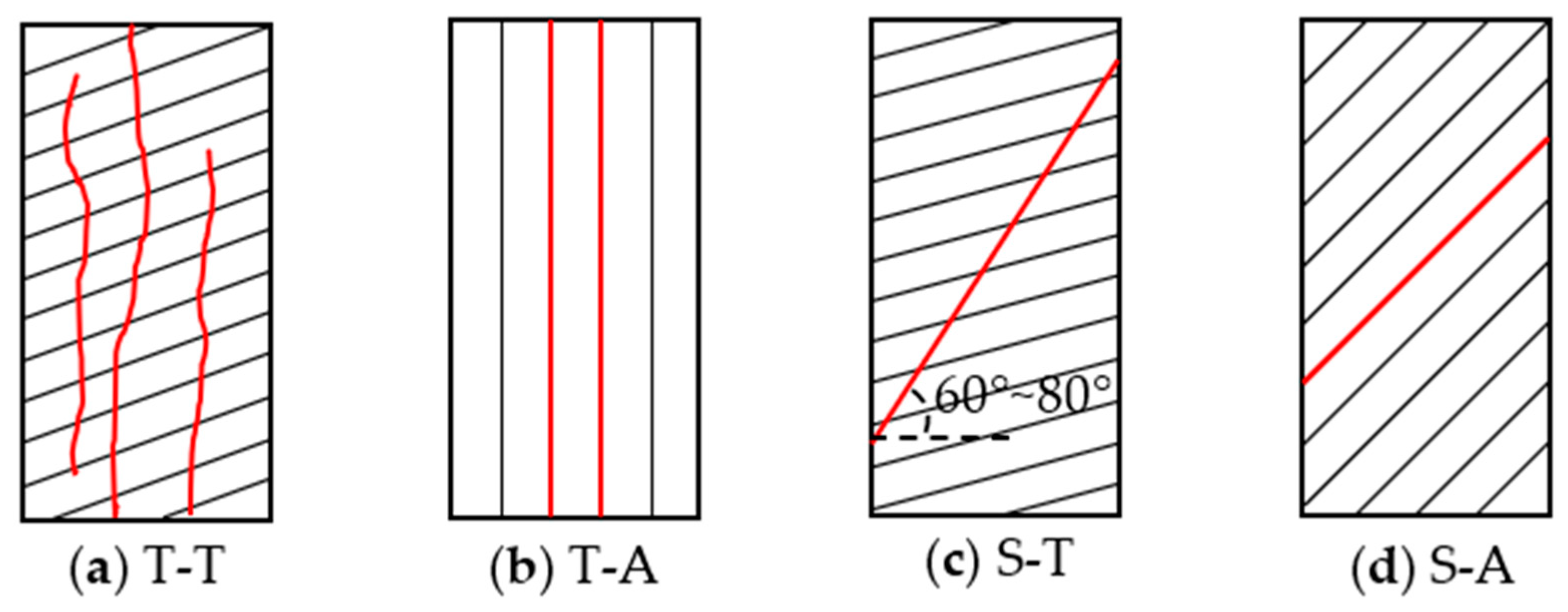
| σ3 = 0 MPa | T-T | T-T | T-T | T-T | S-A | T-T | T-A |
| σ3 = 5 MPa | S-T | S-T | S-T | S-A | S-A | S-A, S-T | S-T |
| σ3 = 10 MPa | S-T | S-T | S-T | S-A, S-T | S-A | S-A, S-T | S-T |
| σ3 = 15 MPa | S-T | S-T | S-T | S-A, S-T | S-A | S-A | S-T |
| σ3 = 20 MPa | S-T | S-T | S-T | S-A, S-T | S-A | S-A | S-T |
| Methods and Specimen Configuration | Graphic Illustration | References |
|---|---|---|
| Centrally cracked circular disc (CCCD) |  | Awaji and Sato [142], Atkinson et al. [143] |
| Semicircular bend specimens (SCB) |  | Chong and Kuruppu [144], Lim et al. [145], Dai et al. [146], Funatsu et al. [147], Ren et al. [148] |
| Single-edged notched beam specimens (SENB) |  | ASTM [149] |
| Straight edge cracked round bar bending specimens (SECRBB) |  | Bush [150] |
| Single edge-notched deep beam specimens (SENDB) |  | Luo et al. [37,151] |
| Chevron-notched beam specimens (CNB) |  | Wu [152] |
| Chevron-notched deep beam specimens (CNDB) |  | Ren et al. [153] |
| Cracked chevron-notched Brazilian disc specimens (CCNBD) |  | Sheity et al. [154], Fowell [155], Dai et al. [156] |
| Chevron-notched semicircular bend specimens (CNSCB) |  | Kuruppu [157], Dai et al. [158] |
| Short-rod specimens (SR) |  | Barker [159], Ouchterlony [160] |
| Traditional Brazilian disk and flatted disk specimens without pre-existing flaws |  | Wang and Xing [161] |
| Shale Material | References | Bedding Orientation | Method | KIc (MPa·m1/2) | Fracture Toughness Ratios | ||
|---|---|---|---|---|---|---|---|
| KIc, A/KIc, ST | KIc, D/KIc, ST | KIc, A/KIc, D | |||||
| Longmaxi shale | Luo et al. [37] | Arrester | NDB | 1.661 | 1.952 | -- | -- |
| Short-Transverse | 0.851 | ||||||
| Heng et al. [45] | Arrester | SECRBB | 1.146 | 2.025 | 1.691 | 1.198 | |
| Divider | 0.957 | ||||||
| Short-Transverse | 0.566 | ||||||
| Wang et al. [165] | Arrester | CCNDB | 0.9226 | 1.313 | -- | -- | |
| Short-Transverse | 0.7028 | ||||||
| Wang et al. [165] | Arrester | SCB | 0.8297 | 1.267 | -- | -- | |
| Short-Transverse | 0.6549 | ||||||
| Dou et al. [166] | Arrester | SENB | 1.366 | 1.476 | -- | -- | |
| Short-Transverse | 0.927 | ||||||
| Ren et al. [153] | Arrester | CNDB | 1.161 | 1.487 | 1.429 | 1.041 | |
| Divider | 1.116 | ||||||
| Short-Transverse | 0.781 | ||||||
| Mancos shale | Chandler et al. [54] | Arrester | SR | 0.44 | 3.667 (ST, low) 1.419 (ST, high) | 3.667 (ST, low) 1.419 (ST, high) | 1.000 |
| Divider | 0.44 | ||||||
| Short-Transverse (low) | 0.12 | ||||||
| Short-Transverse (high) | 0.31 | ||||||
| Chandler et al. [163] | Divider | Double-torsion specimen | 0.48 | -- | 1.297 | -- | |
| Short-Transverse | 0.37 | ||||||
| Li et al. [167] | Arrester | SENB | 0.912 | 0.995 | 1.309 | 0.760 | |
| Divider | 1.200 | ||||||
| Short-Transverse | 0.917 | ||||||
| Lee et al. [53] | Arrester | SCB (25.4 mm in diameter) | 0.944 | -- | -- | 2.0099 | |
| Divider | 0.470 | ||||||
| Arrester | SCB (38.1 mm in diameter) | 0.578 | -- | -- | 1.207 | ||
| Divider | 0.479 | ||||||
| Nash Point shale | Inskip et al. [168] | Arrester | SCB | 0.74 | 3.083 | 2.958 | 1.042 |
| Divider | 0.71 | ||||||
| Short-Transverse | 0.24 | ||||||
| Divider | SR | 0.73 | -- | 2.433 | -- | ||
| Short-Transverse | 0.30 | ||||||
| Anvil Points shale (80 mL/kg kerogen content) | Schmidt [162] | Arrester | SENB | 0.977 | 1.303 | 1.435 | 0.908 |
| Divider | 1.076 | ||||||
| Short-Transverse | 0.750 | ||||||
| Anvil Points shale (160 mL/kg kerogen content) | Arrester | SENB | 0.604 | 1.632 | 1.822 | 0.896 | |
| Divider | 0.674 | ||||||
| Short-Transverse | 0.370 | ||||||
| Test Method | Formulae | References | Remarks |
|---|---|---|---|
| Mineral composition | Jarvie et al. [47] | Wx = weight fraction of component x; Q = quartz; C = carbonate; Cl = clay; Dol = dolomite; TOC = total organic carbon; Lm = limestone; QFM = quartz+feldspar+mica | |
| Rickman et al. [73] | |||
| Wang and Gale [188] | |||
| Jin et al. [189] | |||
| Strength parameters | Hucka and Das [180] | σc = uniaxial compressive strength; σt = Brazilian tensile strength; φ = internal friction angle; ρ = density | |
| Altindag [181] | |||
| Yagiz [184] | |||
| Stress–strain characteristics | Bishop [190] | εp = sustained plastic strain at failure; εe = total elastic strain; εf = total strain at failure; εr = residual strain; σf = stress at failure; σr = residual strength E = elastic modulus; M = post-peak modulus | |
| Hucka and Das [180] | |||
| Andreev [191] | |||
| Andreev [191] | |||
| Luan et al. [192] | |||
| Tarasov and Potvin [179] | |||
| Energy balance analysis | Hucka and Das [180] | Uet = total elastic energy; UP = plastic energy; Ur = rupture energy; Uec = consumed elastic energy; Ua = additional energy; | |
| Tarasov and Potvin [179] | |||
| Munoz et al. [193] | |||
| Ai et al. [194] | |||
Disclaimer/Publisher’s Note: The statements, opinions and data contained in all publications are solely those of the individual author(s) and contributor(s) and not of MDPI and/or the editor(s). MDPI and/or the editor(s) disclaim responsibility for any injury to people or property resulting from any ideas, methods, instructions or products referred to in the content. |
© 2024 by the authors. Licensee MDPI, Basel, Switzerland. This article is an open access article distributed under the terms and conditions of the Creative Commons Attribution (CC BY) license (https://creativecommons.org/licenses/by/4.0/).
Share and Cite
Yin, P.-F.; Yang, S.-Q.; Ranjith, P.G. Anisotropic Mechanical Behaviors of Shale Rock and Their Relation to Hydraulic Fracturing in a Shale Reservoir: A Review. Energies 2024, 17, 1761. https://doi.org/10.3390/en17071761
Yin P-F, Yang S-Q, Ranjith PG. Anisotropic Mechanical Behaviors of Shale Rock and Their Relation to Hydraulic Fracturing in a Shale Reservoir: A Review. Energies. 2024; 17(7):1761. https://doi.org/10.3390/en17071761
Chicago/Turabian StyleYin, Peng-Fei, Sheng-Qi Yang, and Pathegama Gamage Ranjith. 2024. "Anisotropic Mechanical Behaviors of Shale Rock and Their Relation to Hydraulic Fracturing in a Shale Reservoir: A Review" Energies 17, no. 7: 1761. https://doi.org/10.3390/en17071761
APA StyleYin, P.-F., Yang, S.-Q., & Ranjith, P. G. (2024). Anisotropic Mechanical Behaviors of Shale Rock and Their Relation to Hydraulic Fracturing in a Shale Reservoir: A Review. Energies, 17(7), 1761. https://doi.org/10.3390/en17071761