
Numerical Analysis of New PCM Thermal Storage Systems
1
Department of Industrial Engineering (DIN), University of Bologna, Viale Risorgimento 2, 40136 Bologna, Italy
2
Department of Electrical, Electronic and Information Engineering, University of Bologna, Viale Risorgimento 2, 40136 Bologna, Italy
*
Author to whom correspondence should be addressed.
Energies 2024, 17(7), 1772; https://doi.org/10.3390/en17071772
Submission received: 12 February 2024
/
Revised: 8 March 2024
/
Accepted: 3 April 2024
/
Published: 8 April 2024
(This article belongs to the Collection Renewable Energy and Energy Storage Systems)
Abstract
:In this paper, a thermal storage system based on a phase change material is proposed and investigated. The system is composed of several tubes that cross a phase change material mass. A fluid flowing in the tubes charges and discharges the heat storage system. A mathematical model of the system has been developed, which provides the time and space distribution of velocity, temperature, and liquid phase-changing material concentration in a non-stationary regime. A hybrid solution method based on finite volumes and finite differences techniques has been employed for the model equations in the MATLAB environment. To the tubes, a rectangular cross section has been assigned. The performance of the system in terms of accumulated energy density and accumulated power density has been investigated by varying some geometric parameters. The considered geometric parameters influence the number of tubes per unit of system width, the tube hydraulic resistance, the amount of phase change material around each tube, the heat transfer surface of the tube, and the heat storage velocity. In the parametric analysis, peaks have been evidenced in the investigated performance parameters at different instants after the beginning of the heat storage.
1. Introduction
Thermal storage systems play an important role in energy management, as they enable the decoupling of energy production from use. In applications where there is intermittent energy generation, such as in waste energy recovery or solar thermal systems, the adoption of an appropriate storage system is essential. Thermal storage systems based on phase change materials (PCM) allow for high energy storage density with very small temperature variations. A thermal energy storage system with PCM [1] in the configuration of a heat exchanger has been redesigned, concluding that the type, encapsulation shape, and amount of PCM slightly impacted the system’s performance; however, selecting a suitable sensible heat storage material had the highest impact on meeting the system’s targets. A PCM storage system, which therefore utilizes the latent heat of fusion energy, can store from 5 to up to 14 times more heat per unit of volume than a system based only on sensible energy [2]. The first scientific papers in the literature were related to the heating and cooling of buildings, written by Telkes in 1975 [3] and by Lane in 1986 [4]. One of the most promising technologies is combined PV-thermal systems (PVT) [5], where some authors reported an increase in overall efficiency greater than 40% compared with state-of-the art systems. Currently, thermal storage systems designated for heating and cooling buildings are becoming increasingly important due to limited fossil fuel reserves and the need to preserve the environment. Aiming to increase efficiency, “free-cooling” starts to become popular [6,7,8,9]. Free-cooling is understood as a means to store outdoor coolness during the night and supply indoor cooling during the day. The use of PCMs is suitable because of the small temperature difference between daytime indoors and nighttime outdoors. The main parameters that must be taken into account when choosing the most suitable material to be used in a PCM storage tank are: melting temperature, latent heat of fusion, thermal conductivity, chemical and physical stability to thermal cycles, and compatibility with other materials. PCM materials are classified into organic, inorganic, and eutectic mixtures. Numerous systems have been proposed in the latest research with the aim of improving heat transfer in PCM accumulators [10,11,12,13,14,15,16,17,18,19,20,21].
These can be grouped into the following categories:
- PCM material embedded in a metal frame.
- PCM material composed of metal particles with high thermal conductivity.
- Macro and micro encapsulation of the PCM material.
- Use of graphite-composite or other composite PCM materials
- Use of finned tubes.
In general, the PCM exchanges the stored heat with a vector fluid, flowing in a tube or a mantel. Optimizing the shape of the channels that allow the fluid to pass through can be very effective in improving heat storage performance. Some research [22,23,24,25] indicates that the predominant heat transfer mechanism for these storage systems is conduction. Therefore, mainly when the PCM density scarcely varies with temperature and even during the fusion, convective phenomena within the PCM can be neglected. This is the case assumed in the present work, where a PCM heat storage system has been analyzed using a numerical model. The value of some parameters has been changed, describing the heat vector fluid channel geometry. The heat storage performance has been evaluated in order to determine how to increase it and to optimize the system design.
2. PCM Heat Storage
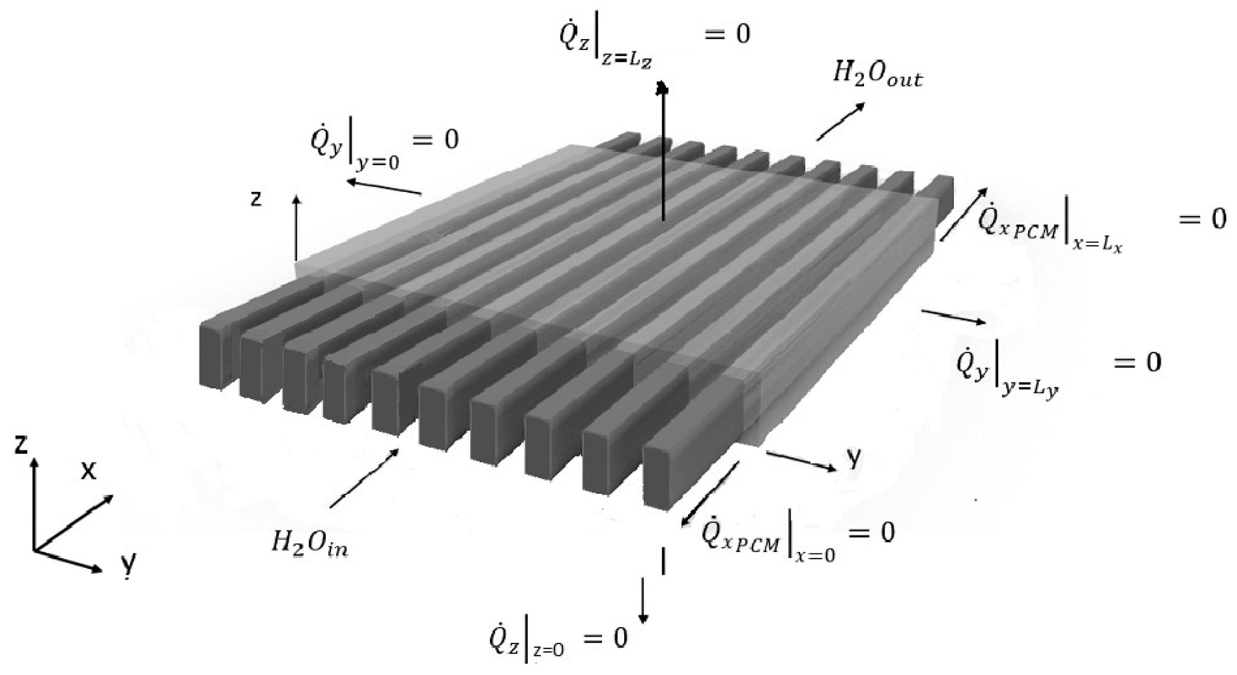
The proposed heat storage system is shown in Figure 1. It is composed of 10 metal thin-walled rectangular cross-section tubes that cross a phase-changing mass. Such a mass is represented in Figure 1 by a gray-transparent color and tubes by a dark gray color. The parts of the tubes outside the phase changing mass are long enough to ensure that the velocity profile in the part inside is completely developed. Moreover, the parts of the tubes outside are thermally insulated.
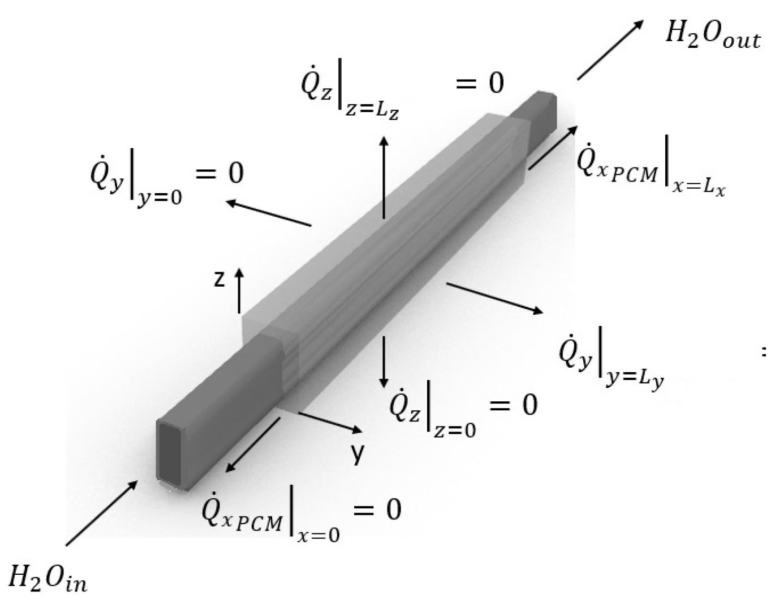
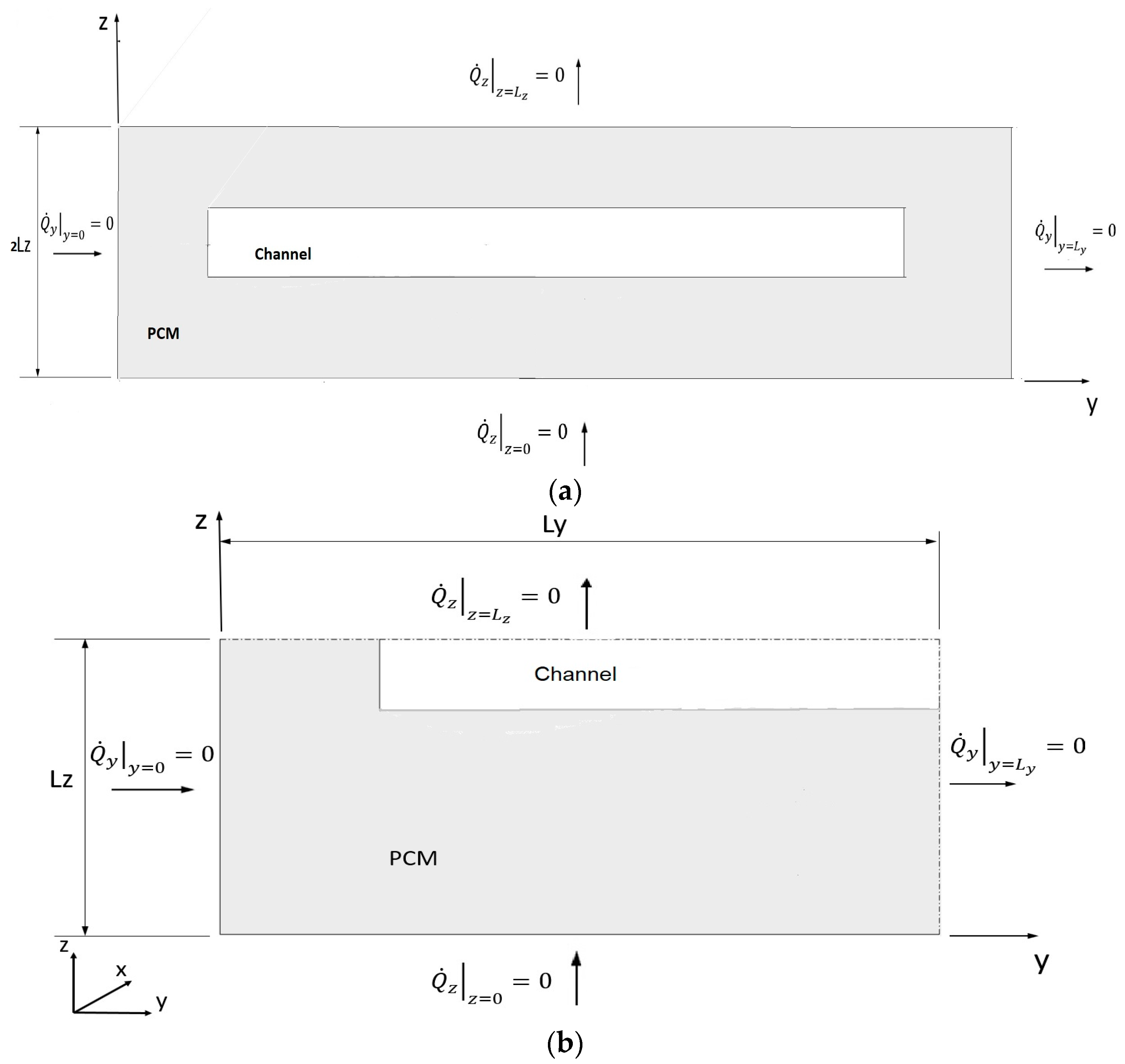
Due to the symmetry of the tubes, the mass, and the boundary conditions, the behavior of the storage system can be investigated by only analyzing the domain depicted in Figure 2 adopting the following boundary conditions:
- , : thermal flux in direction .
- , : thermal storage size in direction .
- , : thermal flux in direction .
- , : thermal storage size in direction .
- , : thermal flux in x-direction, concerning only the PCM material surface.
- , : thermal storage size in direction .
3. Case Study
Let us consider paraffin as the changing phase material and aluminum as metal of the thin-walled tube. Under these conditions, the thermal resistance of the tube wall in the thickness direction is negligible in the heat transfer process, while in the perpendicular direction, the heat conduction is negligible. Therefore, we can only impose that paraffin and water cannot mix together and ignore the presence of the wall for all other effects.
The channel section is shown in Figure 3a.
The channel section has two symmetry axes, one parallel to the z-axis (y = Ly) and one parallel to the y-axis (z = Lz).
Ly = Ly1 + Ly2
This has the advantage of reducing the domain size up to ¼ (Figure 3b) and consequently reducing the calculation time during simulation.
One of the problems in heat propagation lies in the fact that liquid paraffin has a lower thermal conductivity than solid paraffin.
As a consequence, it occurs that as soon as the paraffin in the vicinity of the channel crossed by the hot fluid melts, the thermal conductivity is lowered, resulting in slower heat conduction within the domain.
4. Mathematical Model
The equation for the field of motion of the heat vector fluid is derived from the general Navier–Stokes equation (Equation (1)):
We introduce the following assumptions for the fluid flow:
- Steady-state regime;
- Fully developed laminar flow;
- A duct with a straight axis and constant cross-section with rigid, non-porous walls;
- Constant properties for incompressible Newtonian fluid.
Under these conditions, the only non-zero velocity component remains the axial one: . Moreover, it is possible to write the following relationship: .
Applying the continuity equation , the Navier–Stokes one (Equation (1)) reduces to:
Namely
if expressed in Cartesian coordinates.
The term is not present due to the fully developed flow hypothesis: .
Note that is a scalar, then the Navier–Stokes equation has changed from being a vector, (Equation (1)), to a scalar, (Equation (2)).
, which represents the pressure drop per unit length of the channel, is constant as the motion is hydrodynamically developed.
The boundary condition for the fluid velocity is defined as follows:
, with cw referring to the channel wall.
Referring to the solid part, let us consider the Fourier equation excluding the generative term, which can be written as:
With the thermal diffusivity equal to: .
With regard to the theoretical treatment of the continuity equation referring to the solid/liquid mass, i.e., to a two-phase fluid, the following assumptions and considerations can be made:
- natural convection is neglected, so ;
- and so ;
- ;
- .
Under these assumptions, it is possible to consider the phase transition separately from the heat transfer in the solid phase and the heat transfer in the liquid phase, since these can be described by Equation (4).
With regard to the material in phase transition, thus at constant temperature, the heat flow, instead of causing a change in temperature , causes a change in the value of title :
where ml is the liquid mass and ms is the solid mass.
The energy that enters the infinitesimal control volume of the Fourier equation is equal to the term with the change in temperature over time only when there is no phase change; otherwise, it is equal to the latent heat for the density of the liquid PCM for the change in concentration of the liquid PCM over time.
The boundary condition resulting from thermal insulation in the studied domain is:
while those resulting from symmetries are:
By Fourier’s law, we can write:
The velocity and temperature differential equations have been integrated using a composite finite volume and finite difference method. In particular, the studied spatial domain (corresponding to a quarter of the channel and the amount of PCM it exchanges heat with) has been divided into finite dimensions parallelepiped, disposed in L layers along the x axis. Each layer was composed of M rows of N parallelepiped. The integration of the differential equations in each layer provided the same hydraulic and thermal resistance as in the method employed in [26,27,28,29,30]. The integration between one layer and the other provided conductive thermal resistance for the PCM and hydraulic, conductive, and convective resistance for the heat vector fluid.
The integration of the differential equations in the time dimension has been carried out using the finite difference method. The time domain has been divided into finite time steps. Starting from an initial distribution of velocity, temperature, and PCM liquid concetration for each finite volume of the spatial domain, changes in the latent and sensible thermal energy have been calculated for each parallelepiped by considering the thermal resistance and then obtaining the distribution of velocity, temperature, and PCM liquid concentration for the new time step. The procedure has been iterated until a final instant has been reached.
The solution procedure has been realized in the MATLAB R13 (MATLAB 6.5) environment.
5. Parametric Analysis
Some preliminary simulations have been carried out in order to determine an efficient heat storage system geometry. In each channel, a pressure gradient has been imposed. The initial system temperature (internal fluid + external phase changing mass) is equal to 20 °C; the inlet temperature of the internal fluid is 80 °C from the beginning of the simulation. The melting temperature of the phase-changing mass is equal to 56 °C.
The parameter values of the determined efficient geometry are reported in Table 1.
Such a determined efficient geometry has been assumed as a reference for a subsequent analysis, carried out by separately changing the values of three parameters: Ly1, Lz, and Lz1. The velocity distribution in the heat vector fluid obtained for the reference geometry is reported in Figure 4.
As shown in Figure 4, the velocity is very low, on the order of a few centimeters per second, with a maximum speed of , an average speed of , and a flow rate , relative to the studied domain, i.e., the channel divided into four parts, equal to .
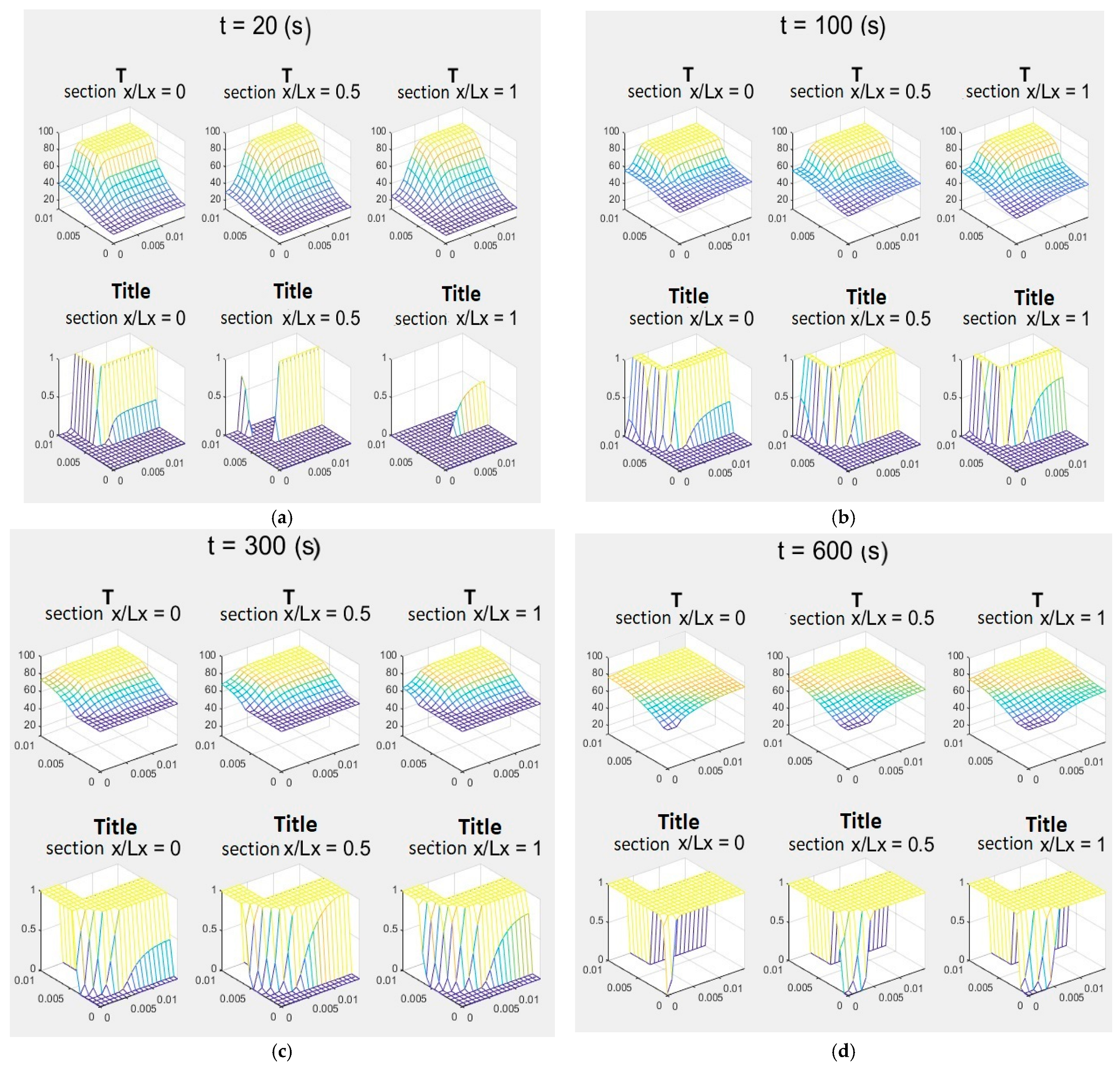
The temperature and liquid PCM concentration in different system sections placed at three points along the heat vector fluid motion direction (x) and in four time instants from the beginning of the simulation are shown in Figure 5.
After only 20 s, the temperatures of the heat vector fluid are uniform and close to the maximum temperature , in all heat storage sections.
First of all, in the first sections of the heat storage, the temperatures of the solid/liquid parts adjacent to the channel rise, melting rapidly. This leads to a sudden drop in heat conduction in those areas, as liquid paraffin has a lower thermal conductivity than solid paraffin. As time passes, heat is transferred to the parts of the solid/liquid material far from the channel walls and to the sections far from the inlet of the heat transfer fluid. The part of the solid/liquid material that melts last is in the section , for , particularly close to .
Figure 6a,b shows the stored energy and power density as a function of time.
The trend of the stored energy density is typical of a negative exponential curve with a horizontal asymptote, as the step-response of a first-order dynamical system.
From the previous graphs, we could also summarize that 99% of energy Qsl per unit of volume accumulates in and 90% of energy Qs accumulates in . The maximum accumulated instantaneous power Q·slmax per unit of volume () is equal to and occurs in the initial instants, at time , after which it decreases until it asymptotically tends to zero.
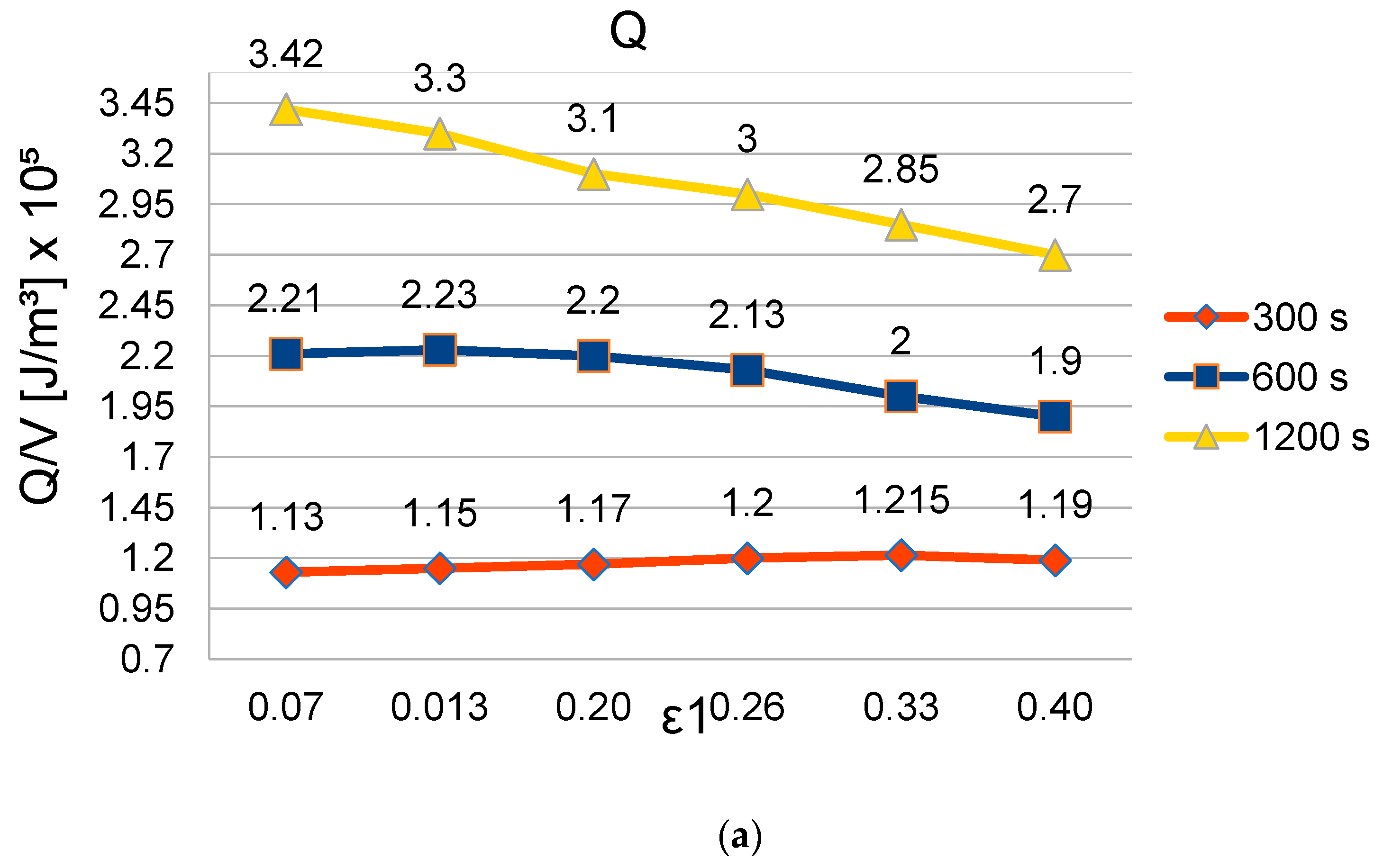
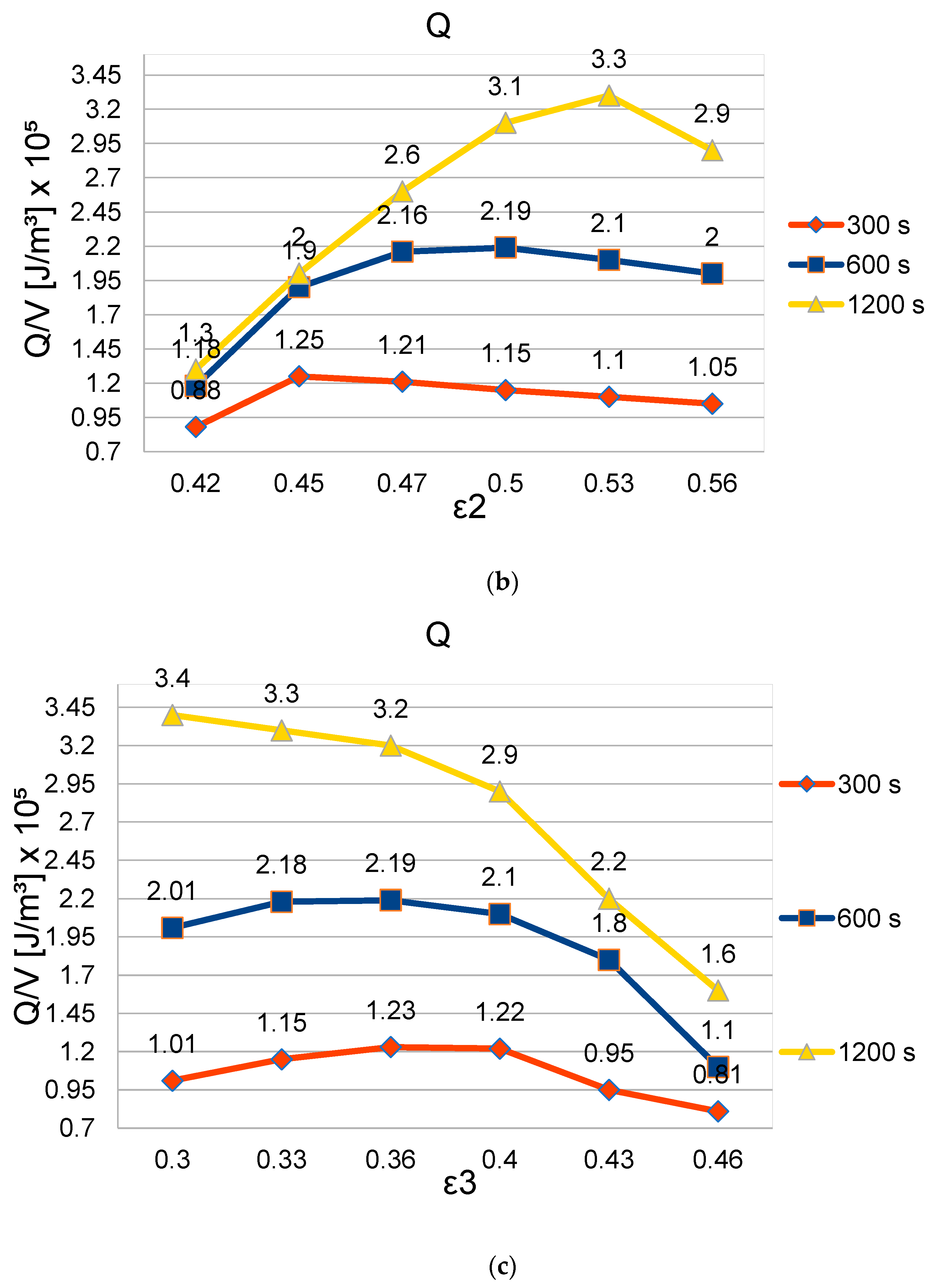
Taking such performances as a reference, a parametric analysis has then been carried out by modifying the geometric parameters of the channel cross section. These are Ly, Ly1, Lz, and Lz1. Dividing the last three by the first one, we obtain three dimensionless parameters: e1, e2, and e3. The parametric analysis has been carried out by varying the dimensionless parameters from +/−20% to +/−40% and by observing the heat stored density after 300, 600, and 1200 s since the beginning of the simulation. The results obtained are shown in Figure 7a–c.
Under the considered conditions, parameters e1, e2, and e3 influence the number of channels per unit of system width, the channel hydraulic resistance, the heat vector fluid mass flow rate, and the amount of PCM around each channel. By reducing e1 and e3, the channel cross-section area decreases, and so the hydraulic resistance increases. Moreover, the heat transfer surface between the PCM and the heat vector fluid is reduced. By increasing the same dimensionless parameters for given e2, the amount of PCM reduces. Therefore, a compromise should be made in order to optimize the system’s performance. In addition, the amount of PCM is determined by e2 when e1 and e3 are given.
Looking at Figure 7a–c, we can also observe how the dimensionless parameters influence the time response of the system. In particular, some parameter configurations that seem to maximize the heat stored per unit of volume around each channel at the beginning of the simulation do not provide the highest value of such a parameter after a longer time.
Due to the complex relationship between the cross section geometric parameters and the heat storage velocity, it is convenient to use an optimization technique in order to maximize the heat stored in the shortest time.
6. Conclusions
In the present work, we proposed a new system for heat storage composed of several tubes crossing a volume containing a phase-changing material. The presented mathematical model allows the heat storage system’s performance to be investigated by varying some geometric parameters. It provides the time and space distribution of velocity, temperature, and liquid phase-changing material concentration in a non-stationary regime. A rectangular cross section has been considered in this study for the tubes. However, more complex geometries described by more parameters can be managed by the model.
The parametric analysis carried out on the energy storage density for our two-phase storage resulted in peaks for each of the main parameters analyzed (Lz, Ly1, Lz1) remaining within the physical as well as geometric constraints. The preliminary results that were obtained show that the proposed heat storage system can reach an accumulated energy density peak near 1.25 × 10⁵ W/m3 in a short time (t = 300 s) and 3.5 × 10⁵ W/m3 in a longer time (t = 1200 s).
Better performances of the proposed heat storage system, in terms of heat stored per unit of volume and storage velocity, will be obtained by utilizing mathematical methods in an optimization procedure, such as a genetic algorithm [26,27,28,29,30], and assigning to the tubes a more complex cross section described by more parameters.
Author Contributions
Conceptualization, G.F. and M.G.; methodology, G.F., M.G. and F.A.; software, G.F., M.G. and F.A.; validation, G.F., M.G. and F.A.; formal analysis, G.F., M.G. and F.A.; investigation, G.F., M.G. and F.A.; resources, G.F., M.G. and F.A.; data curation, G.F. and M.G.; writing—original draft preparation, G.F. and M.G.; writing—review and editing, G.F. and M.G.; visualization, G.F. and M.G.; supervision, G.F. and M.G. All authors have read and agreed to the published version of the manuscript.
Funding
This research received no external funding.
Data Availability Statement
The original contributions presented in the study are included in the article, further inquiries can be directed to the corresponding author.
Conflicts of Interest
The authors declare no conflicts of interest.
Nomenclature
| Al | aluminum |
| cp | specific heat at constant pressure |
| f | refers to the heat transfer fluid |
| l | refers to liquid |
| Lx | Length of channels within the phase changing mass |
| Ly | thermal storage size in direction z |
| Lz | thermal storage size in direction z |
| m | paraffin mass |
| thermal flux in direction z | |
| thermal flux in x-direction, concerning only PCM material surface | |
| thermal flux in direction z | |
| thermal flux in direction y | |
| Q | total energy stored |
| V | thermal storage volume |
| α | thermal diffusivity |
| k | thermal conductivity |
| ρ | density |
| χ | title ratio |
References
- Bernal, I.A.H.; Rivas, A.M.J.; Ortega Del Rosario, M.D.L.A.; Saghir, M.Z. A Redesign Methodology to Improve the Performance of a Thermal Energy Storage with Phase Change Materials: A Numerical Approach. Energies 2022, 15, 960. [Google Scholar] [CrossRef]
- Robaidi, A.A. Development of novel polymer phase change material for heat storage application. Int. J. Mater. Sci. Appl. 2013, 2, 168–172. [Google Scholar] [CrossRef]
- Telkes, M. Thermal storage for solar heating and cooling. In Proceedings of the Workshop on Solar Energy Storage Subsystems for Heating and Cooling of Buildings, Charlottesville, VA, USA, 16–18 April 1975. [Google Scholar]
- Lane, G.A. Solar Heat Storage: Latent Heat Materials. Volume II. Technology; CRC Press: Boca Raton, FL, USA, 1986. [Google Scholar] [CrossRef]
- Hinojosa, J.F.; Moreno, S.F.; Maytorena, V.M. Low-Temperature Applications of Phase Change Materials for Energy Storage: A Descriptive Review. Energies 2023, 16, 3078. [Google Scholar] [CrossRef]
- Zalba, B. Free-Cooling, an Application of PCMs in TES. Ph.D. Thesis, University of Zaragoza, Zaragoza, Spain, 2002. [Google Scholar]
- Vakilaltojjar, S.M.; Saman, W. Analysis and modelling of a phase change storage system for air conditioning applications. Appl. Therm. Eng. 2001, 21, 249–263. [Google Scholar] [CrossRef]
- Vakilaltojjar, S.M.; Saman, W. Domestic heating and cooling with thermal storage. In Proceedings of the Terrastock, Stuttgart, Germany, 28 August–1 September 2000. [Google Scholar]
- Bruno, F.; Saman, W. Testing of a PCM energy storage system for space heating. In Proceedings of the World Renewable Energy Congress VII, Cologne, Germany, 29 June–5 July 2002. [Google Scholar]
- Mulligan, J.C.; Colvin, D.P.; Bryant, Y.G. Microencapsulated phase-change material suspensions for heat transfer in spacecraft thermal systems. J. Spacecr. Rocket. 1996, 33, 278–284. [Google Scholar] [CrossRef]
- Marín, J.M.; Zalba, B.; Cabeza, L.F.; Mehling, H. Improvement of a thermal energy storage using plates with paraffin–graphite composite. Int. J. Heat Mass Transf. 2005, 48, 2561–2570. [Google Scholar] [CrossRef]
- Cabeza, L.F.; Mehling, H.; Hiebler, S.; Ziegler, F. Heat transfer enhancement in water when used as PCM in thermal energy storage. Appl. Therm. Eng. 2002, 22, 1141–1151. [Google Scholar] [CrossRef]
- Mehling, H.; Hiebler, S.; Ziegler, F. Latent heat storage using a PCM–graphite composite material. In Proceedings of the Terrastock 2000—8th International Conference on Thermal Energy Storage, Stuttgart, Germany, 28 August–1 September 2000; pp. 375–380. [Google Scholar]
- Py, X.; Olives, R.; Mauran, S. Paraffin/porous-graphite-matrix composite as a high and constant power thermal storage material. Int. J. Heat Mass Transf. 2001, 44, 2727–2737. [Google Scholar] [CrossRef]
- Xiao, M.; Feng, B.; Gong, K. Thermal performance of a high conductive shape-stabilized thermal storage material. Sol. Energy Mater. Sol. Cells 2001, 69, 293–296. [Google Scholar] [CrossRef]
- Wang, W.; Yang, X.; Fang, Y.; Ding, J. Preparation and performance of form-stable polyethylene glycol/silicon dioxide composites as solid–liquid phase change materials. Appl. Energy 2009, 86, 170–174. [Google Scholar] [CrossRef]
- Wang, W.; Yang, X.; Fang, Y.; Ding, J.; Yan, J. Enhanced thermal conductivity and thermal performance of form-stable composite phase change materials by using ß-aluminum nitride. Appl. Energy 2009, 86, 1196–1200. [Google Scholar] [CrossRef]
- Velraj, R.; Seeniraj, R.V.; Hafner, B.; Faber, C.; Schwarzer, K. Experimental analysis and numerical modelling of inward solidification on a finned vertical tube for a latent heat storage unit. Sol. Energy 1997, 60, 281–290. [Google Scholar] [CrossRef]
- Ismail, K.A.R.; Alves, C.L.F.; Modesto, M.S. Numerical and experimental study on the solidification of PCM around a vertical axially finned isothermal cylinder. Appl. Therm. Eng. 2001, 21, 53–77. [Google Scholar] [CrossRef]
- Sparrow, E.M.; Larson, E.D.; Ramsey, J.W. Freezing on a finned tube for either conduction-controlled or natural-convection-controlled heat transfer. Int. J. Heat Mass Transf. 1981, 24, 273–284. [Google Scholar] [CrossRef]
- Stritih, U. An experimental study of enhanced heat transfer in rectangular PCM thermal storage. Int. J. Heat Mass Transf. 2004, 47, 2841–2847. [Google Scholar] [CrossRef]
- Trp, A. An experimental and numerical investigation of heat transfer during technical grade paraffin melting and solidification in a shell-and-tube latent thermal energy storage unit. Sol. Energy 2005, 79, 648–660. [Google Scholar] [CrossRef]
- Trp, A.; Lenic, K.; Frankovic, B. Analysis of the influence of operating conditions and geometric parameters on heat transfer in water-paraffin shell-and-tube latent thermal energy storage unit. Appl. Therm. Eng. 2006, 26, 1830–1839. [Google Scholar] [CrossRef]
- Erek, A.; İlken, Z.; Acar, M.A. Experimental and numerical investigation of thermal energy storage with a finned tube. Int. J. Energy Res. 2005, 29, 283–301. [Google Scholar] [CrossRef]
- Erek, A.; Ezan, M.A. Experimental and numerical study on charging processes of an ice-on-coil thermal energy storage system. Int. J. Energy Res. 2007, 31, 158–176. [Google Scholar] [CrossRef]
- Fabbri, G. Heat transfer optimization in internally finned tubes under laminar flow conditions. Int. J. Heat Mass Transf. 1998, 41, 1243–1253. [Google Scholar] [CrossRef]
- Fabbri, G.; Greppi, M. An optimized heat sink for thermophotovoltaic panels. J. Appl. Res. Ind. Eng. 2018, 5, 1–9. [Google Scholar]
- Copiello, D.; Fabbri, G. Multi-objective genetic optimization of the heat transfer from longitudinal wavy fins. Int. J. Heat Mass Transf. 2009, 52, 1167–1176. [Google Scholar] [CrossRef]
- Fabbri, G.; Greppi, M.; Lorenzini, M. Optimization with genetic algorithms of PVT system global efficiency. J. Energy Power Eng. 2012, 6, 1035. [Google Scholar] [CrossRef]
- Fabbri, G. Optimum performances of longitudinal convective fins with symmetrical and asymmetrical profiles. Int. J. Heat Fluid Flow 1999, 20, 634–641. [Google Scholar] [CrossRef]
Figure 1.
PCM heat storage with boundaries.

Figure 2.
Single channel with boundaries.

Figure 3.
(a) channel section with boundaries; (b) reduced channel section with boundaries.

Figure 4.
Velocity distribution in the reference channel.
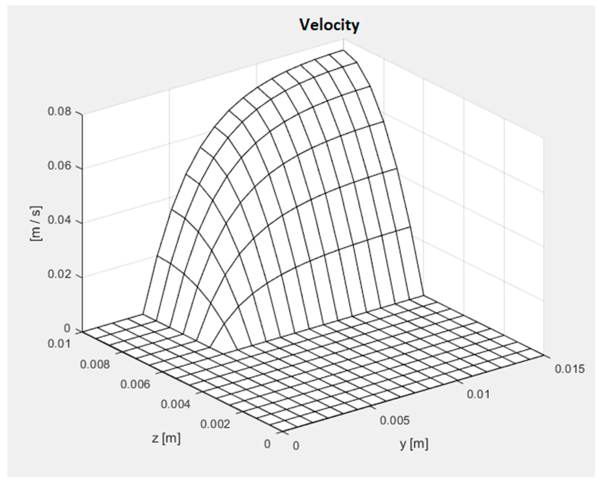
Figure 5.
(a) temperature and title ratio, t = 20 s; (b) temperature and title ratio, t = 100 s; (c) temperature and title ratio, t = 300 s; (d) temperature and title ratio, t = 600 s.
Figure 5.
(a) temperature and title ratio, t = 20 s; (b) temperature and title ratio, t = 100 s; (c) temperature and title ratio, t = 300 s; (d) temperature and title ratio, t = 600 s.

Figure 6.
(a) accumulated energy density; (b) accumulated power density.
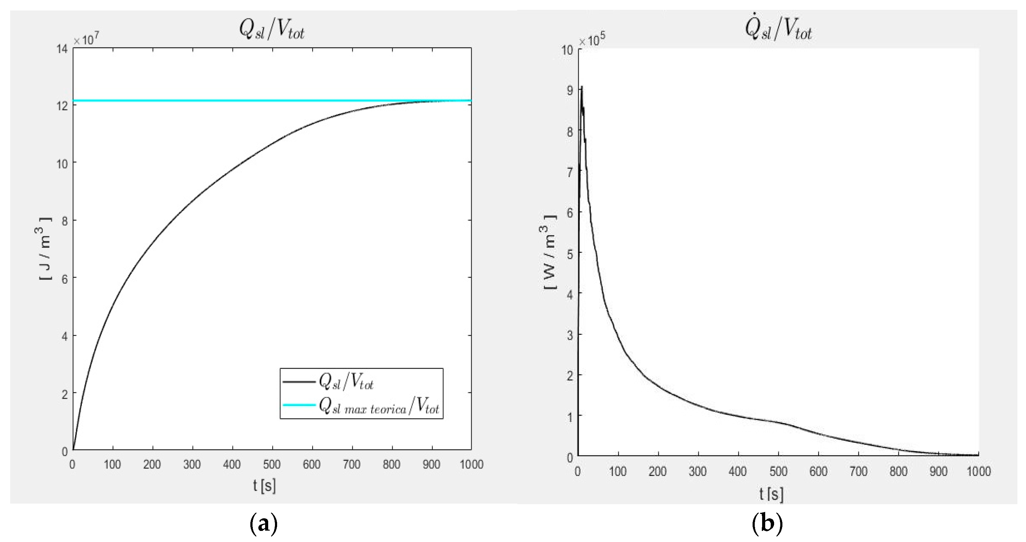
Figure 7.
(a) Q/V (accumulated energy density) vs. parameter variation (+/−20%)_ε1; (b) Q/V (accumulated energy density) vs. parameter variation (+/−20%)_ε2; (c) Q/V (accumulated energy density) vs. parameter variation (+/−20%)_ε3.
Figure 7.
(a) Q/V (accumulated energy density) vs. parameter variation (+/−20%)_ε1; (b) Q/V (accumulated energy density) vs. parameter variation (+/−20%)_ε2; (c) Q/V (accumulated energy density) vs. parameter variation (+/−20%)_ε3.


Table 1.
Geometric Parameters.
Disclaimer/Publisher’s Note: The statements, opinions and data contained in all publications are solely those of the individual author(s) and contributor(s) and not of MDPI and/or the editor(s). MDPI and/or the editor(s) disclaim responsibility for any injury to people or property resulting from any ideas, methods, instructions or products referred to in the content. |
© 2024 by the authors. Licensee MDPI, Basel, Switzerland. This article is an open access article distributed under the terms and conditions of the Creative Commons Attribution (CC BY) license (https://creativecommons.org/licenses/by/4.0/).
Share and Cite
MDPI and ACS Style
Fabbri, G.; Greppi, M.; Amati, F. Numerical Analysis of New PCM Thermal Storage Systems. Energies 2024, 17, 1772. https://doi.org/10.3390/en17071772
AMA Style
Fabbri G, Greppi M, Amati F. Numerical Analysis of New PCM Thermal Storage Systems. Energies. 2024; 17(7):1772. https://doi.org/10.3390/en17071772
Chicago/Turabian StyleFabbri, Giampietro, Matteo Greppi, and Federico Amati. 2024. "Numerical Analysis of New PCM Thermal Storage Systems" Energies 17, no. 7: 1772. https://doi.org/10.3390/en17071772
Note that from the first issue of 2016, this journal uses article numbers instead of page numbers. See further details here.